character+soul
DESCRIPTION
Architectural PortfolioTRANSCRIPT

character+SOULChad Gleason


A #2 pencil and a dream can take you anywhere.Joyce A. Myers


Architecture is character and soul. Character is displayed through quality design, materials and construction, culminating in a tangible and timeless structure. Soul shows through in a dedicated passion for creative, innovative solutions that build value at multiple levels.
Architecture is diffi cult and rewarding. Requiring the reasoning of the engineer and the spatiality of the artist, it is a discipline of extreme balance. Finding this balance is a diffi cult task only achieved through skill, patience and hard work. However, the rewards are timeless—to experience the creation of inspiring spaces is architecture’s greatest reward.
Architecture is structure and enclosure. From the humble confi nes of home to the soaring vaults of a cathedral, structure and enclosure embrace humanity, giving us a place to gather, to sleep, to eat and to play. Th e development of humanity can be tracked through the increasingly complex structures built for these simple tasks—allowing for dreams and imagination to shape the future.
Cast concrete block module created from a digitally designed form mold. Intended for exterior and interior screen wall applications.
character+SOULChad Gleason


north tower lobby
south tower lobby
plaza
Anastasia & DespinaUniversity of Cincinnati
Anastasia…the city appears to you as a whole where no desire is lost and of which you are a part…you can do nothing but inhabit this desire and be content.
Despina…displays one face to the traveler arriving over land and a diff erent one to him who arrives by sea. Each city receives its form from the desert it opposes…a border city between two deserts.
Italo Calvino
Calvino’s description of two fi ctional cities, Anastasia and Despina, captures the essence of Cincinnati’s history and its potential prosperity. Th is narrative served as a generator of ideas for a mixed-use destination in downtown Cincinnati. Designed as a dialogue between two designers, the project’s parti was developed jointly while each building was individually craft ed.
Plan drawing and site model showing location of steetcar route.

The Banks
Riverfront Park
Paul Brown Stadium
Great American Ballpark
Great American
Tower
Fountain Square
Central Business District
Contemporary Arts Center
PLCH MainLibrary
Ohio River
Southern terminus of proposed streetcar route showing route
through downtown and Over-the-Rhine
Site
Over-the-Rhine
Proposed Streetcar
Route
School for Creative & Performing Arts
Music Hall
Findlay Market
Northern terminus of proposed streetcar route
Washington Park
0’ 500’
Furthering the potential success of the building complex is the desire of Cincinnati offi cials to develop the riverfront with a proposed streetcar line to link popular destinations within the city. Located along the projected streetcar route, the site links the project with Th e Banks, Riverfront Park, Fountain Square, the Contemporary Arts Center, Music Hall, and many other existing and future amenities. Th e site stands at the boundary of Over-the-Rhine—a historic, yet impoverished residential area under redevelopment—and Cincinnati’s Central Business District.

Building form takes on the character of an “urban dance” resulting from a partnership between two designers. Th ese push-and-pull forces between programmatic areas and the resulting cantilevers and terraces are clearly visible on the exterior. Shift ing forms give rise to dynamic spaces including habitable rooft op platforms designed for public or private use.
Both towers of the complex off er high-rise urban living with the convenience of a fi tness facility, grocers, restaurants and other retail venues on the lower levels. Among the commercial activities are a below grade movie theater and a vertical market—two amenities which have been absent in the downtown area since its heyday. A large ground-level plaza presents opportunities for gatherings, performances and respite.
Final models were created to plug into a common site model built for the studio. My model is on the left , while my partner’s model is on the right.

penthouse level 1
penthouse level 2
unit section
Unit studies were used to develop a typical apartment language for the complex. Choosing the top floor penthouse apartments, plans, sections and a study model explore the relationships between interior space and the surrounding context.

serial section 1
serial section 2
serial section 3
Serial sections were used to study the relationship between the two towers at different junctions in the site. The result of those refinements are shown in this final rendering showing the surrounding context.
As Anastasia, the complex rejuvenates the downtown area, acting as a powerful catalyst for further development. As Despina, it serves as a parallax between the deserts of the individual and the collective, between antiquity and modernity. Its location, convenience and potential as a hub of social activity fosters a sense of urban identity, reviving the golden days of The Queen City.

Top: Hospitality level plan.Bottom: Barrel storage level plan.Opposite top: 3D SketchUp model.Opposite bottom: ACAD elevations.

Th e Law Family Vineyards in Paso Robles, California consists of both production and hospitality functions. Nestled into the crest of a mountain, the design overlooks the surrounding hillsides and vineyards. Th e design exploits the site for maximum benefi t and impact, allowing for vertical and horizontal layering with a progression of spaces and programmatic functions. Th e initial program calls for a 5,000 case winery with fermentation, barrel and casegood storage, crush pad, assorted support spaces and a hospitality wing for tastings and special events. An overlook on the north side of the wine cave provides dramatic views across the valley below.
My involvement on this project started during the initial schematic design phase. Responsibilities included development of plans, sections and elevations in AutoCAD, a corresponding 3D model in Sketchup, consultant coordination and design input.
Law Family WineryBAR Architects


Wellness CenterUniversity of Cincinnati
The Wellness Center at Cranbrook Academy evolved from the asymmetrical interplay of views and axes developed by Eliel Saarinen’s masterplan. Extending the campus as intended while reinterpreting Cranbrook in a modern vernacular are the driving forces behind the design. While the morphology of Cranbrook is evident in the external arrangement of the building, the same principles were used to define interior space as well as the finer details of connections and joints. The idea of slippage, offset and asymmetry derived from Saarinen play a large role in the development of the project from the level of the door to the arrangement of rooms. At each level a sense of connection between dissimilar elements is achieved as space flows physically or visually between each other in order to achieve a sense of connection between the users of the Center and promote wellness through the act of interaction.
The interplay of opposites continues through campus with a series of hard and soft edges, symmetry and asymmetry. As the design developed, these qualities became more and more a driving force. The desire to modernize the vocabulary of Saarinen while incorporating his original intentions produced the final scheme of the project.
Section perspective through main spa.

pedestrianvehicular
main axesstudio axis
outdoor space
natatorium
library/museum
path of the chinese dog
friendship gate
Flying the studio over the extended Friendship Gate path, develops a dialogue with both the Natatorium and the Gate. As a result, the residential units are placed on the western side of the site, nestled amongst evergreen trees as a shelter from winter winds and the late summer sun while providing visitors a quiet retreat. On the east, the public portion of the program is arranged around a series of courtyards, again extending Saarinen’s original language for the campus.
A southern courtyard defi ned by the building on the north and east, and walled off from the upper Grand Allee, provides a sense of privacy and enclosure for year-round use. A northern terrace provides refuge from the summer sun and is seen as a more remote space with light use, providing a solitary retreat.
Extending the building onto the Grand Allee at the second level provides for a connection between the upper and lower levels and demarcates the Grand Allee zone from the lower Natatorium zone while simultaneously reinforcing the existing axis of the Chinese Dog without negating the original intention of Williams and Tsien’s design for the Natatorium.
Site model showing relationship between the new Wellness Center and the existing campus, including the Natatorium and the Grand Allee.

3
1
2
6
7
4 5
12
9
11
13
13
13
13
13
8
10
18
18
18
main level0’ 50’
1. lobby 2. women’s locker 3. men’s locker 4. women’s sauna 5. men’s sauna 6. plunge pool
7. aromatherapy pool 8. main therapy pool 9. cold pool10. hot pool11. kitchen/dining12. library
13. residential unit14. open to below15. studio16. massage17. office18. meditation
second level
15
14
17 16
16
16 18
14

roof assembly: membrane on metal deck with steel bar joists and drop ceiling
second fl oor assembly: lightweight concrete on metal deck with steel joists
ground fl oor assembly: cast in place concrete pools with raised access fl ooring
interior window units
modular thermal stor-age wall with custom base plate
curtainwall with vertical structural mullions
shade fi n/mullion
rebar
led strip lightingair intake
interior windowhorizontal mullionsglazing
vertical structural mullions
anchor bolts
custom base plate
concrete footing
trench gutter
Detail of exterior envelope at main spa showing thermal storage and curtain walls.
Exploded axiometric drawing of main spa structural system showing both horizontal and vertical components.

Assembly of components is standard in modern construction. With the wide availability of modular construction materials, the need for custom designed pieces is rare. In the design of the Wellness Center such a condition arises in the thermal storage wall, where customized modular construction is employed. Th e nature of the wall relies on a series of modular storage tanks designed to fi t together and provide a self-supporting structural wall. Along with the wall, a custom base provides connection to the ground while a custom beam cap spans the length of the wall and provides a connection to the roof surface. Other components of the assemblage are standard construction materials chosen for their role in spanning and supporting the necessary structural forces of the design.
lighting
mullion embedded in wall framefl ashing
coping mechanism
neoprene gasket
metal panel cladding
custom frame with integrated gutter and lighting
double pane insulated glazing
Section perspective through hospitality wing. Detail of bathroom skylight and gu tter below.


Strip My MallUniversity of Cincinnati
As banal as they are ubiquitous, strip malls add little to either architectural experience or a sense of community. Current developer driven models favor maximum profi t for the mall’s owners and neglect individual and community experience. Shopping has become a predominant force in the world, aff ecting society, culture and the individual through the rise of economic societies, culminating in a culture of comfort and leisure. Despite the negative implications of rising individualism, capitalism, zoning, suburbia and their eff ects on architecture, fresh approaches to designing places for shopping and community can include a series of strategies for personal and community engagement.
Th is thesis proposes an alternative ownership model, and specifi c design treatments with an enhanced regional focus, by which the Greenhills Shopping Center, in the northern suburbs of Cincinnati, can be revitalized to stand as an active, social, economic and community hub. Transferring ownership of the center to the community with a focus on small businesses empowers residents and recycles profi ts back to the village to create a sustainable asset. Sensual, engaging architecture aimed at reconnecting the human mind and body can be used to combat the dull, monotonous environment of strip malls. Th rough the use of movement, transparency, form, color and materials, a multisensory experience enhances personal engagement. Also, reaching outside of the immediate community to become a regional destination places the center and the village in a position for success.
Specifi c design solutions include a new housing component to the north combined with a revitalized center. Anchored by a new iconic market hall that provides a new identity for Greenhills, the project also includes a new pedestrian plaza, retail and offi ce space. Contrasting the original renovated brick storefronts, a wooden canopy and walkway weaves through the center tying together old and new in a rich new layer of history and meaning.
Above: Before and aft er. Th e current state of the Greenhills shopping center shows its age and decline. A renewed center activates the surrounding area to provide a place to gather, socialize and play.Left : A new courtyard and market building anchor the redevelopment of the shopping center into a year-round lifestyle destination.

20001980 2012 Proposed19601938 Built1938 Proposed
Deletion Addition RenovationRestoration Substitution
1938 Proposed
1938 Built
1960 1980 2000 2012Proposed
Greenhills Shopping Center
Initial plans for the shopping center included two wings surrounding a central courtyard space at the rear of the facility. Due to budget constraints the original footprint of the center was reduced to one wing and a service station on the northwest corner.
By the 1950s, growth of Greenhills placed increasing demands on the center and subsequent expansion. The initial plan was changed to fill in the central open zone and extend the center the the north to connect with the service station. This expansion included office space with multiple stories. By 1965, the center further expanded with several outbuildings added to the north and south sides of the center.
Run as a co-op until 1978, the shopping center stood at the heart of the community providing all the necessary goods and services from groceries, a post office, barber shop, dentists and more. Today, the fire department has moved up the road and the general decline of the center has resulted in a loss of tenants and resulting income for the village. Current management has let the center fall into disrepair with no plans for upkeep, maintenance or improvements.

Win
ton
Rd
.
Esw
in S
t.
Esw
in S
t.
Enf
ield
St.
Enf
ield
St.
Enfield St.
Endicott St.
New Housing
Indoor Skate Park
Ice House
Canopy Spine
Plaza
Stair Slide
Fountain
Bocce Court Ice Rink
New Health & Fitness Wing
New Art & Office Space
Community Center
Village Green
Greenhills Swim Club
Greenhills Tennis Club
Greenhills Golf Course
Greenhills Community Building
A new masterplan for the Greenhills A new masterplan for the Greenhills Shopping Center capitalizes on the existing Shopping Center capitalizes on the existing urban infrastructure with the addition of urban infrastructure with the addition of multi-family housing and expansion of the multi-family housing and expansion of the center. Amenities such as healthcare, fi tness center. Amenities such as healthcare, fi tness facilities and a community center add to facilities and a community center add to the existing library, post offi ce and other the existing library, post offi ce and other shops. With these transformations center is shops. With these transformations center is transformed into a true Town Center.transformed into a true Town Center.

Over the years an initial Utopian vision of urban planning has been altered into a hodge-podge of additions and modifi cations followed by neglect. In it’s current state, the center is a palimpsest of the original design vision. As visioned, the new design would scrape away the layers to restore the original modernist visage while adding and altering unsuccessful pieces to restore the center to its true mission—that of a gathering place for the community, a place to share, a place to play and a place to dream.
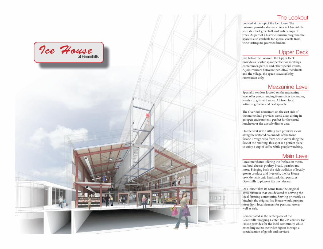
Main LevelLocal merchants off ering the freshest in meats, seafood, cheese, poultry, bread, pastries and more. Bringing back the rich tradition of locally grown produce and livestock, the Ice House provides an iconic landmark that prepares Greenhills to pioneer the next dream.
Ice House takes its name from the original 1938 business that was devoted to serving the local farming community. Serving primarily as butcher, the original Ice House would prepare meat from local farmers for personal use as well as sale.
Reincarnated as the centerpiece of the Greenhills Shopping Center, the 21st century Ice House provides for the local community while extending out to the wider region through a specialization of goods and services.
Mezzanine LevelSpecialty vendors located on the mezzanine level off er goods ranging from spices to candles, jewelry to gift s and more. All from local artisans, growers and craft speople.
Th e Overlook restaurant on the east side of the market hall provides world class dining in an open environment, perfect for the casual luncheon or the upscale dinner date.
On the west side a sitting area provides views along the restored colonnade of the front facade. Designed to force acute views along the face of the building, this spot is a perfect place to enjoy a cup of coff ee while people watching.
The LookoutLocated at the top of the Ice House, Th e Lookout provides dramatic views of Greenhills with its intact greenbelt and lush canopy of trees. As part of a historic tourism program, the space is also available for special events from wine tastings to gourmet dinners.
Upper DeckJust below the Lookout, the Upper Deck provides a fl exible space perfect for meetings, conferences, parties and other special events. A joint venture between the GHSC merchants and the village, the space is available by reservation only.
Ice Houseat Greenhills

Top: First level plan.Left: Third level plan.Right: Longitudinal section. Opposite: 3D model study.

1321 DeHaro Street is a multi-family residense situated on a steep hill in San Francisco. This design replaces a single family home with three units. Designed around the topography of the site, the building steps up the hillside allowing for a series of outdoor terraces and dramatic views. Windows on the open side of the lot allow for light to reach the interior and provide views outside. With adjoinging properties on the other side, a stair running the height of the building provides a buffer zone between neighbors while allowing access to the property from above or below. A rich pallette of materials, including wood and metal, complement the striking modern design.
My involvement on this project started during the initial schematic design phase. Responsibilities included development and refinement of plans, sections and elevations in AutoCAD. At the same time, a corresponding 3D model in Sketchup was created.
1321 DeHaro StreetTheodore Brown & Partners


Studio Kandinsky is a design that explores the qualities and attributes of natural light in a design in� uenced by the work of a prominent artist. Wassily Kandinsky was chosen as the artist for this project which includes a reading room, a studio and gallery space. Analysis of the both the artist and the lighting requirements for the three di� erent spaces led to the � nal design.
Kandinsky’s deep intellect and knowledge of art theory led him to develop a set of rules governing point, line and plane. � ese rules were used in the development of the design. � e circle was used as a central organizing element as it the most peaceful shape, represents the human soul and “comes closest to the fourth dimension.” In this area the reading room is placed as a central area of knowledge and peace.
� e studio area was designed around the triangle. Kandinsky believed the artist was at the head of an acute angled triangle, leading the way into the future through the expression of his art. As such, the studio celebrates the artist’s philosophy in addition to providing a sharp contrast and resultant harmony to the overall composition.
For the gallery space, the design revolves around right angles, predominantly, the rectangle. � is shape corresponds to the color red for Kandinsky and relates a lively feeling—a movement in oneself. � e gallery has been broken up into several spaces providing for increased lighting as well as display space. With the placement of a re� ecting pool behind the gallery, they appear to � oat in space—the treasures inside waiting to be discovered.
Studio KandinskyCosumnes River College


VelodromeUniversity of Cincinnati
Velodrome creates a state of the art cycling center to provide fitness, education and community programs to promote cycling as a sport as well as a healthy lifestyle. The center’s goal is to promote and advocate cycling to all ages and levels of experience as more than just a fitness activity—in fact, it’s a lifestyle. From youth programs to Master’s level racing, the target audience consists of enthusiasts as well as the casual cyclist. Youth and commuting programs aim to capture a wider audience and develop future interest in cycling. The center will be a focal point for Eden Park and a destination for cyclists all around the region and beyond with a dynamic, energetic design that captures the movement and essence of cycling.
Nestled into a low spot along a hillside bordered by woods to the east and on the north an old reservoir wall separates Mirror Lake on the high side of the wall. Remnants of the reservoir wall to the south are evident and covers approximately 50% of the southern edge. A berm to the west completes the sunken bowl of the old reservoir. The southwest corner transitions from the adjacent street to a parking lot on the corner of the site—a low, flat point of the site serving as the elevation for the old reservoir basin. The distinct borders and sunken nature of the site provide the opportunity for insertion of a velodrome at this level and place supporting building elements at a higher level to connect with Mirror Lake as an upper terrace. The slope of the site at the south creates opportunities for dramatic views both to and from the building by exploiting the change in elevation and the relative closeness of the Ohio River.
Models and drawings drove the development of this design. Shown here are a series of initial study models exploring overall form, structure and enclosure.Top: Initial form and site model.Middle: Fragment model of main entrance studying enclosure and the relationship between the new building and the existing reservoir wall.Bottom: Structural study model exploring the roof and its support.

Final building model on CNC milled site.

Top: Longitudinal section through track and lobby with structural studies.Middle left : Main level plan.Middle right: Mezzanine level plan.Lower left : Transverse section through velodrome track.
Resurrecting latent forces of the reservoir creates potential to integrate the existing built structures on the site with newly constructed elements. Site orientation and the shape of the reservoir bowl are well suited to exploit solar design principles while utilizing passive design strategies to emphasize fi tness and health. Exterior landscape areas provide an opportunity for further recreation, fi tness and leisure pursuits. Th e wooded area to the east can be used as a base for mountain bike skills classes while an area to the south can be used for road cycling skills.
Lungs are the powerhouse of our human existence and are used as the inspiration for the design—without them we would be nothing. For cyclists, the lungs are their most powerful and potent resource. Th e ability to intake, process and exhale oxygen at a high rate and deliver it quickly to muscle tissue is the essence of all professional and elite level racing. In the case of this project, the lungs can be thought a of as the central resource or connection to all components. Circulation and the layout of programmatic spaces will be loosely tied to a model of the human lung.


SketchOn the Water


PhotographyFragments

AB ANCHOR BOLT AC AIR CONDITIONING A/C ASPHALTIC CONCRETE ACOUST ACOUSTICAL ADI ADJUSTABLE AGGR AGGREGATE AL OR ALUMINUM ALUM ALT ALTERNATE APPROX APPROXIMATE ARCH ARCHITECT ASPH ASPHALT AT ACOUSTICAL TILE BD BOARD BLDG BUILDING BTM BOTTOM BLK BLOCK CAB CABINET CB CATCH BASIN CC CENTER TO CENTER CEM CEMENT CER CERAMIC CFM CUBIC FEET/MINUTE CI CAST IRON CLG CEILING CLR CLEAR CMP CORRUGATED METAL PIPE CNTR COUNTER COL COLUMN COMP COMPOSITION CONC CONCRETE CONN CONNECTION CONST CONSTRUCTION CONTR CONTRACTOR COTG CLEAN OUT TO GRADE CORR CORRIDOR CSK COUNTERSINK CT CERAMIC TILE CTR CENTER CW COLD WATER CWR COLD WATER RISER DBL DOUBLE DD DOOR DIMENSION DEPT DEPARTMENT DET DETAIL DF DOUGLAS FIR DI DROP INLET DIA DIAMETER DN DOWN DR DOOR DS DOWNSPOUT DW DISHWASHER DWG DRAWING DWR DRAWER E EAST EA EACH/EXHAUST AIR EJ EXPANSION JOINT ELECT ELECTRICAL ELEV ELEVATION EMER EMERGENCY EMT ELECTRICAL METALLIC TUBING ENCL ENCLOSURE EQ EQUAL EQUIP EQUIPMENT EWC ELECTRIC WATER COOLER EXIST EXISTING EXP EXPANSION EXP AGG EXPOSED AGGREGATE EXP EXPOSED EXT EXTERIOR FA FIRE ALARM FB FLAT BAR FC FRAMING CLIP FD FLOOR DRAIN FDN FOUNDATION FE FIRE EXTINGUISHER FEC FIRE EXTINGUISHER CAB. FHWS FLATHEAD WOOD SCREW FIN FINISH FLR FLOOR FLASH FLASHING FLDG FOLDING
FLUOR FLUORESCENT FND FEMININE NAPKIN DISPENSER FOC FACE OF CONCRETE FOF FACE OF FINISH FOM FACE OF MASONRY FOS FACE OF STUDS FT FOOT OR FEET FTG FOOTING FUT FUTURE GA GAUGE GALV GALVANIZED GB GYPSUM BOARD GI GALVANIZED IRON GL GLASS GLULAM GLUE LAMINATED GPM GALLONS/MINUTE GYPBD GYPSUM BOARD
HB HOSE BIB HBD HARDBOARD HC HOLLOW CORE HD HOLD DOWN HDWD HARDWOOD HDWE HARDWARE HM HOLLOW METAL HORIZ HORIZONTAL HR HOUR/HANDRAIL HT HEIGHT HW HOT WATER HWR HOT WATER RISER ID INSIDE DIAMETERjDIM IN INCH INV INVERT INCL INCLUDING INSUL INSULATION INT INTERIOR IPS INSIDE PIPE SIZE JAN JANITOR JT JOINT KD KILN DRIED KIT KITCHEN KW KILOWATT LAB LABORATORY LAM LAMINATE LAV LAVATORY LB POUND LT LIGHT MAT MATERIAL MAX MAXIMUM MACH MACHINE MB MACHINE BOLT MC MEDICINE CABINET MCB METAL CASING BEAD MECH MECHANICAL MEMB MEMBRANE MET METAL MFGR MANUFACTURER MH MANHOLE MIN MINIMUM MISC MISCELLANEOUS MO MASONRY OPENING MTD MOUNTED N NORTH NIC NOT IN CONTRACT NO OR# NUMBER NOM NOMINAL NTS NOT TO SCALE OC ON CENTER OD OUTSIDE DIAMETER/DIM OFF OFFICE OPNG OPENING OPP OPPOSITE OZ OUNCE PART P ARTICLE/PARTITION PLAS PLASTER/PLASTIC PLGL PLATE GLASS PLYWD PLYWOOD PM PRESSED METAL PR PAIR
PREFAB PREFABRICATED PSI POUNDS/SQUARE INCH PT POINT PTD PAPER TOWEL DISP QT QUARRY TILE R RISER RAD RADIUS RD ROOF DRAIN REBAR REINFORCING BAR REF REFERENCE REFR REFRIGERATOR REINF REINFORCING REQ REQUIRED RESIL RESILIENT RH ROUND HEAD RHWS ROUND HEAD WOOD SCREW RM ROOM RO ROUGH OPENING RPM REVOLUTIONS/MINUTE RWL RAINWATER LEADER S SOUTH SC SOLID CORE SCHED SCHEDULESD SOAP DISPENSER SECT SECTION SH SHELF SHR SHOWER SHT SHEET SIM SIMILAR SMS SHEET METAL SCREW SND SANITARY NAPKIN DISP SNR SANITARY NAPKIN REC SP STRUCTURAL PLYWOOD SPEC SPECIFICATION SQ SQUARE S/S SERVICE SINK STA STATION STD STANDARD STGR STAGGER STL STEEL STOR STORAGE STRUCT STRUCTURAL SUSP SUSPENDED SYM SYMMETRICAL
TB TOWEL BARTC TOP OF CURB TEL TELEPHONE TER TERRAZZO T&G TONGUE AND GROOVE TF TOP OF FRAMING TP TOP OF PAVEMENT TPD TOILET PAPER DISP TPH TOILET PAPER HOLDER TV TELEVISION TW TOP OF WALL TYP TYPICAL UL UNDERWRITERS LABORATORIES
VCT VINYL COMPOSITE TILE VERT VERTICAL VF VINYL FABRIC VG VERTICAL GRAIN W WEST WC WATER CLOSET WD WOOD WSCT WAINSCOT WP WATERPROOF WR WASTE RECEPTICAL WT WEIGHT YD YARD & AND @ AT / PER # POUND/NUMBER 0/ OVER W/ WITH W/O WITHOUT (E) EXISTING (N) NEW
ABBREVIATIONS
SITE NOTES:
1. GRADE SITE AS INDICATED ON SITE PLAN. GRADE TO AVOID ON-SITE WATER RETENTION AND DRAINAGE ONTO ADJACENT SITES. SEE CIVIL ENGINEER'S GRADING PLAN. NOTIFY PROJECT DESIGNER OF ANY DISCREPANCIES. 2. PROVIDE A MINIMUM OF 2% GRADE SLOPE AWAY FROM THE BUILDING PAD FORA DISTANCE OF NOT LESS THAN 5'-0". SURFACE DRAINAGE OVER DRIVEWAYS AND SIDEWALKS IS PROHIB-ITED WHEN THE AREA TO BE DRAINED EXCEEDS ¼ ACRE. 3. ANY SURVEY MONUMENT WITHIN THE AREA OF CONSTRUCTION SHALL BE PRESERVED OR RESET BY A REGISTERED CIVIL ENGINEER OR LICENSED LAND SURVEYOR. VERIFY, LOCATE AND INDICATE ALL PROPERTY CORNERS, SETBACKS, EASE-MENTS AND BUILDING LOCATION CORNERS PRIOR TO FOUNDATION INSPECTION. 4. ALL FOOTINGS SHALL REST ON FIRM NATURAL SOIL OR COMPACTED FILL. SEE SOILS ENGINEERS REPORT FOR GROUND SURFACE PREPARATION.
INDEX
SHEET # PAGE # TITLE
1 T-1 TITLE SHEET/SITE PLAN2 A-1 FLOOR PLANS3 A-2 FLOOR PLANS/SCHEDULES4 A-3 FOUNDATION PLANS5 A-4 EXTERIOR ELEVATIONS6 A-5 EXTERIOR ELEVATIONS/SECTION7 A-6 FRAMING PLANS8 A-7 FRAMING PLANS9 A-8 INTERIOR ELEVATIONS10 A-9 ELECTRICAL PLANS11 A-10 DETAILS 12 A-11 DETAILS
SYMBOLS
BUILDING DATA
CONSTRUCTION: TYPE V- NO HOUR
OCCUPANCY: R-3 SINGLE FAMILY RESIDENCE
AREA: RESIDENCE: 1ST FLOOR: 895 SF 2ND FLOOR: 915 SF 3RD FLOOR: 120 SF TOTAL: 1930 SF GARAGE: 240 SF TOTAL BLDG. AREA: 2170 SF
CODE: 2007 CBC CA BUILDING CODE VOL. I AND II 2007 CPC CA PLUMBING CODE 2007 CMC CA MECHANICAL CODE 2007 CEC CA ELECTRICAL CODE 2007 CA ENERGY STANDARDS ARE REFERENCED
VICINTY MAP
SECTION
SHEET NO.
DETAIL
SHEET NO.
DETAIL
SHEET NO.
DOOR WINDOW
SACRAMENTO INFILL HOUSING9505 P STREET
SACRAMENTO, CA 95785
INT. ELEV. DETAIL ROOM DESIGNATION

AppendixResidential CD Set
Sacramento Infill Housing is a design for housing on vacant blocks in the inner city of Sacramento, California. Designed to fit a standard lot size in the city with rear alley access, the project consists of a complete set of construction documents for a light residential structure. Two foundation options are presented, one for a slab on grade foundation and one for a wood floor foundation with piers and footers. The set also contains framing, electrical and standard detail plans along with notes and schedules for constructing the house.


INTERIOR FINISH SCHEDULENO. ROOM FLOOR BASE WALLS CEILING CEILING HT. REMARKS
101 ENTRY/HALL WOOD WOOD GYP. BD. GYP. BD. 8'-0"102 LIVING ROOM WOOD WOOD GYP. BD. GYP. BD. 9'-0"103 DINING ROOM WOOD WOOD GYP. BD. GYP. BD. 9'-0"104 KITCHEN WOOD WOOD GYP. BD. GYP. BD. 9'-0"105 BATH TILE TILE GYP. BD. GYP. BD. 9'-0"201 HALL WOOD WOOD GYP. BD. GYP. BD. 8'-0"202 MASTER BEDROOM CARPET WOOD GYP. BD. GYP. BD. 9'-0"203 MASTER BATH TILE TILE GYP. BD. GYP. BD. 9'-0"204 BATH/LAUNDRY TILE TILE GYP. BD. GYP. BD. 9'-0"205 BEDROOM CARPET WOOD GYP. BD. GYP. BD. 9'-0"206 BEDROOM CARPET WOOD GYP. BD. GYP. BD. 9'-0"301 HALL WOOD WOOD GYP. BD. GYP. BD. 8'-0"302 UTILITY LINOLEUM COVE GYP. BD. GYP. BD. 9'-0"
WINDOW SCHEDULESYM. WIDTH HEIGHT TYPE FRAME HEAD JAMB SILL REMARKS
W1 4'-6" 5'-0" DB HUNG WOOD 1/A-2 2/A-2 3/A-2 7'6" TOP HEIGHT TYP.W2 3'-3" 5'-0" DB HUNG WOOD 1/A-2 2/A-2 3/A-2W3 6'-0" 7'-0" BIFOLD WOOD 1/A-2 2/A-2 3/A-2 WINDOW WALLW4 2'-8" 6'-0" FIXED WOOD 1/A-2 2/A-2 3/A-2W5 6'-6" 5'-0" DB HUNG WOOD 1/A-2 2/A-2 3/A-2W6 6'-6" 3'-6" CSEMNT WOOD 1/A-2 2/A-2 3/A-2W7 1'-4" 3'-6" FIXED WOOD 1/A-2 2/A-2 3/A-2W8 4'-6" 4'-0" DB HUNG WOOD 1/A-2 2/A-2 3/A-2W9 3'-6" 4'-0" DB HUNG WOOD 1/A-2 2/A-2 3/A-2W10 3'-6" 5'-0" DB HUNG WOOD 1/A-2 2/A-2 3/A-2
KCOLB SSALGLYNIVDEXIF"0-'5"0-'311WKCOLB SSALGLYNIVDEXIF"0-'5"4-'121W
SSALG DETSORFDOOWDLOFIB"6-'1"2-'231W
DOOR SCHEDULESYM. WIDTH HEIGHT THICK TYPE MATERIAL HC/SC HEAD JAMB SILL REMARKS
D1 3'-0" 7'-0" 1 3/4" PANEL WOOD SC 7/A-2 8/A-2 9/A-2D2 3'-0" 7'-0" 1 3/4" FRENCH WOOD SC 7/A-2 8/A-2 9/A-2D3 2'-6" 7'-0" 1 3/4" PANEL WOOD SC 4/A-2 5/A-2 6/A-2D4 2'-4" 7'-0" 1 3/4" BYPASS WOOD SC 4/A-2 5/A-2 6/A-2D5 3'-0" 7'-0" 1 3/4" BYPASS WOOD SC 4/A-2 5/A-2 6/A-2D6 2'-6" 7'-0" 1 3/4" BYPASS WOOD SC 4/A-2 5/A-2 6/A-2D7 2'-4" 7'-0" 1 3/4" PANEL WOOD SC 4/A-2 5/A-2 6/A-2D8 3'-0" 7'-0" 1 3/4" SLAB WOOD SC 7/A-2 8/A-2 9/A-2D9 8'-0" 7'-0" 1 3/4" GARAGE WOOD SC


