characterizing subsurface structures and determining in-situ … · 2020-02-26 · proceedings,...
TRANSCRIPT

PROCEEDINGS, 45th Workshop on Geothermal Reservoir Engineering
Stanford University, Stanford, California, February 10-12, 2020
SGP-TR-216
1
Characterizing Subsurface Structures and Determining In-Situ Stress Orientation Using
Fullbore Formation MicroImager (FMI) and Sonic Scanner: A Case Study from
FORGE Well 21-31, Fallon, Nevada, USA
Tito Satria Putra Perdana1, Logan Hackett
1, and Ann Roberson-Tait
1
1GeothermEx, a Schlumberger Company, Richmond, California
[email protected], [email protected], [email protected]
Keywords: FMI, Sonic Scanner, FORGE, Fallon, Fracture, Fracture Analysis, Fracture Classification, Fracture Orientation, Fracture
Zone, Conductive Fracture, Resistive Fracture, Open Fracture, Closed Fracture, Possible Fault
ABSTRACT
Targeting structurally controlled permeability in geothermal fields remains a challenge because of the difficulties in characterizing
subsurface structures in terms of their hydraulic behavior within the reservoir. Measurement sensitivity in combination with
approximately 80% circumferential coverage (in an 8-1/2-inch wellbore) makes the Fullbore Formation MicroImager (FMI) useful for
identifying subsurface structures and providing direct data on in-situ stress orientations in the formation intersected in the logged
interval. Accurate, high-resolution wellbore images paired with skilled image interpretation enables fractures and faults to be
characterized as open (hydraulically conductive) or closed (non-conductive, typically due to mineral deposition). Knowledge of the
depths and orientations of permeable structures is beneficial at the local scale (within the logged well) and at the reservoir scale. The
improved understanding of permeability distribution is used to optimize operations and improve decisions about future well targets in
conventional hydrothermal projects and particularly in Enhanced Geothermal Systems (EGS) projects.
FORGE well 21-31 in the Fallon geothermal area of Nevada was logged on behalf of the U.S. Department of Energy’s Geothermal
Technologies office using Schlumberger’s FMI, Platform Express Triple Combo, Sonic Scanner, and Temperature and Pressure Survey
tools. These logs were run in the 8-1/2-inch diameter production interval of the well (6,080-8,139 feet-MD), and the results have been
analyzed and interpreted. This has enabled improved classification of fractures, including basic properties (direction, density/intensity,
and aperture), and determination of whether the fractures are open or healed. With respect to the last, the sensitivity of the measurement
of borehole imaging plus the broad range of Stoneley-mode frequencies have been particularly valuable. Electrically-conductive
fractures are observed in much of the logged interval; they show a dominant strike orientation of NNE-SSW, with dip magnitudes
mostly in the range of 60°-88°. Drilling-induced fractures and borehole breakouts are also observed, with dip statistics showing a
dominant strike orientation of NNE-SSW for drilling induced fractures and ESE-WNW for borehole breakouts. Well 21-31 is vertical;
thus the strikes of drilling induced fractures and borehole breakouts tend to align with the trends of maximum and minimum horizontal
stresses, respectively. The interpretation of the logging results is consistent with the predominant structural / tectonic trend in the area
(most mapped faults are oriented N-S to NNE-SSW).
1. INTRODUCTION
The FMI tool generates an electrical image of a borehole from 192 microresistivity measurements. Special focusing circuitry ensures
that the measuring currents are forced into the formation, where they are modulated in amplitude with the formation conductivities to
produce low-frequency signals with petrophysical and lithological information and a high-resolution component that provides the
micro-resistivity data used for imaging and dip interpretation. The spacing of the button electrodes, innovative pad and flap design, and
high frequency of data transmitted by the digital telemetry system result in a vertical and azimuthal resolution of 0.2 inches; this means
that the dimension of any feature that is 0.2 inches or larger can be readily estimated from the image. The size of features smaller than
0.2 inches can be estimated by quantifying the current flow to the electrode. Fine-scale details such as 50 micrometer (0.05 millimeter)
fractures filled with conductive fluids are visible on FMI logs.
The sensitivity of the measurement in combination with approximately 80% circumferential coverage (in 8-1/2-inch wellbore) makes
the FMI useful for identifying subsurface structures and providing direct data on in-situ stress orientations in the formation intersected
in the logged interval. Accurate, high-resolution FMI images paired with skilled image interpretation enables fractures and faults to be
characterized as conductive (possibly “open”, hydraulically conductive) or resistive (“closed”, non-conductive, typically due to mineral
deposition).
“Conductive fractures” identified from FMI may represent two types of electrically-conductive fractures: an open (filled by conductive
mud) fracture; or a pyrite-filled / clay-filled fracture. Thus, integrating the results of fracture analysis from FMI with the results of Sonic
Scanner data processing and interpretation is recommended. When an open fracture intercepts the borehole, the Stoneley wave from the
Sonic Scanner tool causes well fluid to be pumped in and out of the fracture, thus dissipating energy; this results in attenuation of the
Stoneley wave. At the same time, the change in acoustic impedance causes a reflection of part of the signal. So, the effects of open
fractures on the Stoneley are: (a) Stoneley amplitude reduction (attenuation), and (b) Stoneley reflection. Besides of its sensitivity to

Perdana et al.
2
fractures, Stoneley reflection is also sensitive to borehole size and lithological changes in the borehole that should be considered in the
fracture interpretation.
FORGE well 21-31 is located in the Fallon geothermal area in Churchill County, Nevada (Latitude: 39.39°, Longitude: -118.7°, at an
elevation of 3,928 feet above sea level (asl)). It was drilled and completed to a total depth of 8,139 feet between 5 February – 31 March
2018. The well was drilled in three sections: 17-1/2-inches from 130 to 910 feet; 12-1/4-inches from 910 to 6,058 feet; and 8-1/2-
inches from 6,058 to 8,100 feet. The well is vertical to a depth of about 7,000 feet. A very small (3°) SW inclination developed from
7,000 feet to TD. On behalf the US Department of Energy’s Geothermal Technologies office (via a contract with Sandia National
Laboratories (“Sandia”)), this well was logged using Schlumberger’s Triple Combo, sonic and caliper logs from 300 to 6,062 feet;
Schlumberger’s FMI, Sonic Scanner, and external temperature from 6,055 to 8,109 feet; and Schlumberger’s Triple Combo from 5,970
to 8,139 feet. Sidewall cores (1-1/2-inch x 3-inch and 1 x 2-inches) were then cut at multiple depths, ranging from 8,075 through 6,435
feet, retrieving a total of 45 sidewall core samples. The FORGE 21-31 well was injection tested on two different occasions: 4 March
and 13-15 March 2018. In summary, injection testing identified that a few discrete zones of high permeability were encountered during
drilling in otherwise low permeability basement rock. Wellbore analytical analysis of injection test data indicated the fractures with
high permeability have a short cumulative thickness in the FORGE 21-31 well, which are embedded within a rock mass that otherwise
has very low permeability of approximately 0.01 mD.
In the 8-1/2-inch section of the well (6,055-8,109 feet-MD), a total of 2,054 feet (626 meters) of FMI and Sonic Scanner logging results
have been analyzed and interpreted using the Schlumberger’s Techlog* wellbore software platform. The aforementioned logs were run
in the production interval of the well, which passes through rhyolite-tuff, basalt, quartzite, metapelite, and felsic intrusion rock
formations. For this evaluation, we relied primarily on the following data: FMI image logs, sonic logs, temperature and pressure logs,
caliper logs, standard open-hole logs (which include gamma ray (GR), resistivity (AT10, AT20, AT30, AT60, and AT90), neutron-
porosity, and density), lithological log plots from cutting analysis, and lost circulation intervals (from drilling reports). The main
objective of this study is to provide detailed subsurface structure interpretation of FORGE well 21-31, including fracture classification
and determination of the orientation and density of fractures.
For the 8-1/2-inch interval where FMI and Sonic Scanner data have been collected, we have performed the following: FMI image
processing, FMI image interpretation, Stoneley Fracture Analysis, and integrated fracture interpretation and analysis using FMI and
Sonic Scanner.
1.1 FMI Image Processing
The primary purpose of computer processing of raw resistivity data is to convert the raw data into the best visual representation of the
borehole. Proper conditioning of the data is achieved using certain correction algorithms, prominent examples of which are:
1.1.1 Image Correction / Equalization
Processing of the FMI data was carried out on the Techlog platform using the Well Bore Imaging (WBI) workflow. A basic QC test of
the inclinometry data from raw images was used to determine if the borehole image is correctly oriented. This test computed the offsets
needed to correct accelerometer and magnetometer variables and determined if correction was required. The main Speed correction
module in Techlog was used, using frame time and Z-axis acceleration to compute tool acceleration and tool velocity at every depth.
Tool sticking is detected to avoid incorrect computation of the variables when the tool is temporarily stuck. The speed corrected image
are then normalized using Histogram Equalization module.
1.1.2 Image Orientation
The image is oriented with respect to the north of the borehole.
1.1.3 Image Depth Shift / Depth Match
When logging tools are run in sequence, differences always occur in depth from tool to tool and from run to run due to differential cable
stretch. Stretch can be pronounced when the logging string sticks or temporarily hangs up in the hole. All logging measurements must
be adjusted to a common depth reference before data processing can continue. All depths should be referenced to a base log. The base
log is selected from a logging tool where strong or forceful tool positioning is not used (e.g., GR log from Triple Combo). Free-moving
tools travel through the borehole more smoothly than tools that are pushed with great force against the borehole wall. For this reason,
strongly centralized tools (e.g., FMI tool) are not selected as the base log.
1.1.4 Image Normalization
The image is normalized by assigning a color spectrum of user-defined bins set to the resistivity data to obtain image pixels that are
representative of a particular bin size. When all pixels are viewed together the normalized image is produced. Two types of
normalization – static and dynamic – are performed.
In static normalization a preferred spectrum of colors (128) is distributed over the data interval. This technique provides a good overall
representation of the data, highlighting major resistivity variations. Higher resolution normalization is achieved through the process of
* Mark of Schlumberger

Perdana et al.
3
dynamic normalization, where a preferred spectrum of colors (up to 128) is distributed over a 1-meter window length. A sliding
window method is applied to the whole data interval. The normalized images thus produce the optimize image of the resistivity data
and are usually presented side-by-side on interpretation plots.
1.2 FMI Interpretation
The processing of FMI images was followed by interactive dip picking and feature classification using normalized images. The dip
picking enabled computation of the dip angle of lithological boundary, fracture, fault, and/or any other planar features. Drilling-induced
fractures and borehole breakouts were also easily recognizable in most situations with these resistivity images. Interactive dip picking
was performed manually using a sine wave, with its amplitude and azimuth fitted to planar features on the image.
1.3 Stoneley Fracture Analysis
The Stoneley fracture analysis was performed to distinguish open (permeable) fractures and closed fractures. Stoneley fracture analysis
uses the Stoneley slowness and Stoneley waveform to compute the reflection and the transmission coefficient which indicate the energy
loss to the formation. On the other hand, Fast Stoneley Modeling uses the compressional and the shear slowness to model the synthetic
Stoneley waveform which is caused by bed boundaries and also uses the density log to model the synthetic Stoneley waveform which is
caused by borehole enlargement. The result of this modeling is used to compute the synthetic reflection and the synthetic transmission
coefficient. The reflection coefficients from these two analyses are then compared to determine whether the Stoneley Reflection is
caused by open fractures, borehole enlargement or bed boundaries.
1.4 Integrated Fracture Interpretation and Analysis using FMI and Sonic Scanner
Integrated fracture interpretation and analysis using FMI and Sonic Scanner are conducted to better classify the natural fractures, to get
the fracture properties (direction and density / intensity), to better determine whether the fractures are open or closed, and to assess the
permeability of the subsurface fault or fracture. With the sensitivity of the measurement of borehole imaging (and in combination with
their circumferential coverage) and with the broad range of Stoneley-mode frequencies acquired by the Sonic Scanner tool, the open
natural fractures are reliably characterized.
2. RESULTS OF FMI AND SONIC SCANNER PROCESSING AND INTERPRETATION
2.1 FMI Log Quality and Borehole Conditions
FMI log inclinometry data (collected using the General Purpose Inclinometry Tool (“GPIT”)) show good coherency with the well
deviation and well azimuth data, indicating that the tool was correctly oriented in the borehole and that the calculated dips are correct.
The borehole conditions are generally good, with only a few large and minor washouts, and the image quality is generally good to
excellent. Evident borehole washouts in the intervals of 6,298-6,313 feet-MD, 7,358-7,363 feet-MD, and 8,049-8,094 feet-MD
adversely affected the FMI Image quality, but fractures and faults could still be identified and analyzed.
The FMI images are in general on-depth with standard open-hole logs from Triple Combo (e.g., GR, resistivity, neutron-porosity, and
density).
2.2 FMI Manual Dip Classification
Structural features were picked manually using sine waves, with their amplitudes and azimuths fitted to planar features on the borehole
image. The lowest point of the sinusoid troughs defines the dip azimuths, and the amplitude of the sinusoids define the dip magnitudes.
All dip interpretations have been made using a combination of static and dynamic normalized images, along with gamma-ray,
resistivity, and neutron-porosity logs, results of cutting analysis, and lost circulation intervals from drilling reports.
In resistivity images, the fractures that have conductive traces (represented by dark colors) are termed conductive fractures. The
fractures are further classified into continuous conductive fractures and discontinuous conductive fractures, based on their appearance
and continuity across the borehole diameter. GeothermEx focused especially on conductive fractures which, due to invasion of
conductive drilling mud, are conventionally assumed to be open and hydraulically conductive, although care must be taken with such an
assumption because conductive fractures can also be clay-filled or pyrite-filled.
Fractures with resistive traces (represented by white / light colors) are termed resistive fractures. Resistive fractures are generally
considered to be closed or healed (filled with resistive minerals such as calcite and quartz).
Possible faults are similar in appearance to fractures, but they show indications of displacement and/or truncation.
Drilling-induced tensile fractures and borehole breakouts were oriented by fitting sinusoids to these features where they occur on
opposite sides of the borehole wall. Although these features do not have a dip direction or dip magnitude, their strikes can be defined
and used to indicate the maximum and minimum horizontal stress directions.
Sedimentary dips generally reflect depositional processes and attitudes, but the interval logged in FORGE well 21-31 is comprised of
metamorphic and igneous rock formations. The lithologies (as defined by cutting analysis) are mainly altered-rhyolite, altered-basalt,
quartzite, metapelite, and felsic intrusion. The facies changes seen on the FMI image are marked as lithologic boundaries (Figure 1).

Perdana et al.
4
Lithologic-boundary dip statistics in the interval show dominant azimuth orientations of northerly (NNW, N, NNE) and southeasterly.
Dip magnitudes are highly variable, from nearly horizontal to approximately 75°. Foliation surfaces are also observed on the FMI
image; these features are developed in the meta-sedimentary rocks (metapelite) and appear as a repetitive layering (could be conductive
and/or resistive) inside the metamorphic rocks (Figure 1). Foliation-surface dip statistics in the interval show dominant azimuth
orientations of northerly (NNW, N, NNE) and southeasterly. Main dip magnitudes are from approximately 30° to 40°.
Figure 1: FMI image example of lithologic boundary at 7,008 feet-MD associated with sharp facies change (below 7,008 feet-
MD: metamorphic rock; above 7,008 feet-MD: felsic intrusion).
2.3 FMI Structural Interpretation
Structural interpretation includes identifying and determining the orientation of features with a tectonic origin (including fractures and
faults) and determining the present-day tectonic stress field orientation from drilling-induced features and borehole breakouts. Detailed
fracture analysis, consisting of fracture classification, fracture orientation, and fracture density analysis, was performed for the interval
of 6,055 - 8,109 feet-MD.
2.3.1 Regional Geologic Setting
The Fallon site is in the Carson Sink, a large composite basin in the Basin and Range Province. The general stratigraphy of the area is
Late-Miocene to Quaternary basin-fill sediments (<4,900 feet thick) overlying Miocene volcanic rocks (2,300-4,250 feet thick), and pre-
Miocene lithologies consisting of volcanic and meta-sedimentary rocks intruded by felsic plutons (Kraal and Ayling, 2019). The site is
situated in a west-tilted half graben cut by widely spaced N-S to NNE-SSW striking normal faults with approximately 200 m of
displacement (Siler et al., 2019). Dip magnitudes of these faults vary from approximately 50° to 70°.
No Quaternary faults have been observed within the Fallon site, and only a few small (< M.2.0) historic earthquakes have occurred at
the site. The Rainbow Mountains fault (approximately 10-15 km east of the Fallon site) ruptured in 1954 during a M 6.9 earthquake,
accommodating oblique normal-dextral motion (Caskey et al., 2004). The Rainbow Mountains fault terminates southward near the Salt
Wells geothermal field, 15 km to the southeast of the FORGE site. Increased permeability associated with the horse-tailing southern
end of this fault corresponds with the production well field at Salt Sites (Hinz et al., 2014). It is notable that most geothermal systems in
the Great Basin region are proximal to recent faults (Bell and Ramelli, 2007; Faulds et al., 2015). The absence of Quaternary faulting at
the Fallon site may explain the lack of sufficient permeability in the area (Hinz et al., 2016).
The primary lithologies encountered at the Fallon site in the basin fill are: a) Quaternary-Tertiary sediments, b) Miocene mafic volcanic
rocks, primarily basalt, but also lithic tuff, andesite, rhyodacite, and volcanic breccia, and c) pre-Miocene volcanic, plutonic, and
metamorphic rocks, consisting of 1) felsic volcanic rocks, primarily rhyolitic tuff, 2) felsic intrusions, 3) quartzite with lesser volcanics,

Perdana et al.
5
intrusions, marble, and meta-pelites, 4) lesser mafic and intermediate volcanic rocks (Kraal et al., in prep). The ages of the pre-Miocene
lithologies are somewhat uncertain and are currently under investigation: recently-obtained age dates from the rhyolite tuff at 7975-8140
ft depth are Oligocene, and work is ongoing to constrain the ages of other pre-Miocene formations. Proposed lithologies for EGS
stimulation include the felsic intrusion, quartzite, or altered-rhyolite. The deepest wells in the Fallon site terminate in pre-Miocene
lithologies at 6,929-9,468 feet-MD and record maximum bottom-hole temperatures of 194 to 214°C (Blankenship et al., 2018).
2.3.2 FMI Fracture Types, Morphology, and Orientation
Fractures are well developed over almost the entire interval logged. The fractures identified are almost exclusively conductive
(considered to be open). Some resistive (considered to be closed) fractures were also recognized in the studied interval. As discussed
above, conductive fractures are further classified as either continuous or discontinuous; respectively they can be seen to be continuous
around the borehole on the image, or discontinuous around the borehole. Fracture types, morphology, and orientation are described
below:
Discontinuous Conductive Fractures: The predominant fracture type, they appear as linear fractures that do not completely transect the
borehole (Figure 2). Even though discontinuous, where the open section includes the peak and/or trough of the trace, the fracture can
safely be considered of natural origin. Where the fracture is discontinuous, and the trace only follows the sinewave limbs, but does not
describe the sinewave peak or trough, then it might be drilling-induced, or, possibly, a closed fracture that has been partly opened by the
drilling process. Discontinuous-open-fracture dip statistics over the interval demonstrate a dominant strike orientation of NNE-SSW,
with WNW and ESE azimuths (Figure 3). Dip magnitudes for this fracture type are highly variable, from approximately 15° to nearly
vertical (88°), but mainly from 65° to 80° (Figure 3). These discontinuous conductive fracture orientations reflect the major structural /
tectonic trend in the area (N-S to NNE-SSW) as discussed under Regional Geologic Setting.
Continuous Conductive Fractures: Relatively rare compared to the discontinuous conductive fractures, they completely transect the
borehole without a break in the fracture trace on the FMI image (Figure 2). These fractures may also represent discontinuous fractures
that have been cut by the borehole in a continuous section. Away from the borehole they might be discontinuous. Continuous-open-
fracture dip statistics in the interval indicate dominant strike orientations of N-S, NNE-SSW, and NE-SW with westerly and
southeasterly azimuths (Figure 4). The dip magnitudes of the continuous open fractures vary from approximately 20° to 80° vertical,
but they are mainly from 60° to 70° (Figure 4). These continuous conductive fracture orientations represent the major structural /
tectonic trend in the area (N-S to NNE-SSW) as discussed in the Regional Geologic Setting.
Resistive Fractures: Fractures with resistive traces are interpreted to be resistive (or closed / healed) fractures. Resistive-fracture dip
statistics over the interval demonstrate dominant strike orientations of NW-SE, N-S, and NNE-SSW, with northeasterly, easterly, and
southwesterly azimuths. Dip magnitudes for this fracture type are highly variable, from 40° to approximately 80°, but mainly in the
range of 50° to 80°.

Perdana et al.
6
Figure 2: FMI image example of continuous conductive fractures and discontinuous conductive fractures in the felsic intrusion.
Figure 3: Discontinuous-conductive-fracture dip statistics in FORGE Well 21-31 interval 6,055 - 8,109 feet-MD. Discontinuous-
open-fracture dip statistics over the interval demonstrate a dominant strike orientation of NNE-SSW, with WNW and
ESE azimuths. Dip magnitudes for this fracture type are highly variable, from approximately 15° to nearly vertical, but
mainly from 65° to 80°.
Figure 4: Continuous-conductive-fracture dip statistics in FORGE Well 21-31 interval 6,055 - 8,109 feet-MD. Continuous-
open-fracture dip statistics in the interval indicate dominant strike orientations of N-S, NNE-SSW, and NE-SW with
westerly and southeasterly azimuths. The dip magnitudes of the continuous open fractures vary from approximately 20°
to 80° vertical, but they are mainly from 60° to 70°.

Perdana et al.
7
2.3.3 FMI Identification of Possible Faults: Morphology and Orientation
The factors generally considered for locating possible faults on the borehole images are:
abrupt changes in foliation dip attitude (either magnitude or azimuth) across the plane of the feature;
large high-angle, conductive or resistive events developed across the wellbore;
enlarged hole at the fault / borehole intersection;
shift in the trend of in-situ stress;
abrupt termination of layers and/or fractures on the plane of the feature;
changing thickness of the fault bounded layer across the wellbore;
occurrence of fractures around the fault intersection; and
abrupt changes in log response across the feature interpreted as a fault.
Several possible faults were identified based on the above criteria, with diagnostic features including (but not restricted to): indications
of large conductive events developed across the wellbore (Figure 5), enlarged hole at possible faults, abrupt termination of fractures and
foliation surfaces on the possible fault plane (Figures 5 and 6), sharp facies changes (Figures 5 and 6), dip magnitude and / or azimuth
changes of foliation surfaces (Figures 5 and 6), and occurrence of fractures around the possible fault intersection. Previous
interpretation of seismic reflection and gravity data across the Fallon FORGE site did not identify or predict any major fault
intersections in the pre-Miocene section in well 21-31 or the other deep wells at the site (82-36, FOH-3D, 61-36; Siler et al., 2019),
however it is possible that there are small faults present that could not be resolved in these geophysical data.
Possible-fault dip statistics demonstrate a dominant strike orientation of NNE-SSW, with westerly and easterly azimuths (Figure 7).
Dip magnitudes vary from 10o to nearly vertical but are mainly from 50° to 80o (Figure 7). These possible-fault orientations represent
the major structural / tectonic trend in the area (N-S to NNE-SSW with dip magnitudes from approximately 50° to 70°).
Figure 5: FMI image example of possible faults at 6607,5.5 feet-MD, 6,611.5 feet-MD, and 6,615 feet-MD. These interpreted
faults are associated with abrupt termination of foliation surfaces on the possible faults’ planes, sharp facies changes, dip
magnitude and azimuth changes of foliation surfaces, large conductive events developed across the borehole along the
possible faults’ planes, and good development of conductive fractures near the possible faults’ planes.
Perdana et al.
8
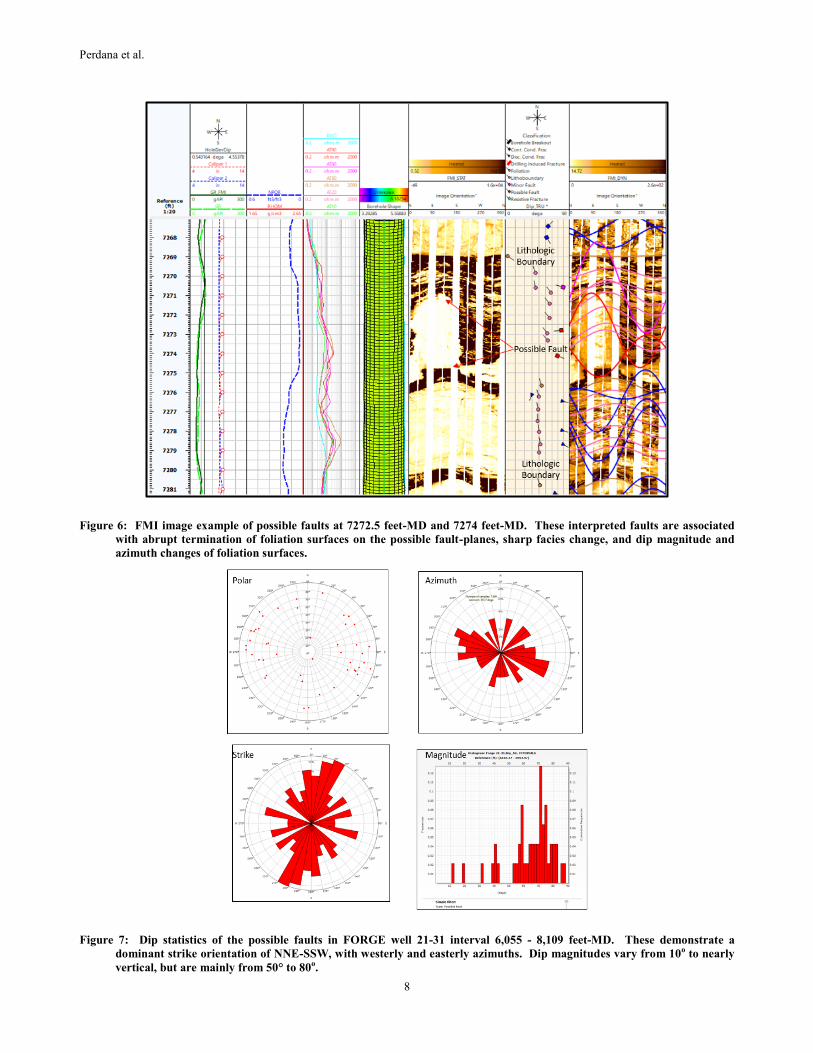
Figure 6: FMI image example of possible faults at 7272.5 feet-MD and 7274 feet-MD. These interpreted faults are associated
with abrupt termination of foliation surfaces on the possible fault-planes, sharp facies change, and dip magnitude and
azimuth changes of foliation surfaces.
Figure 7: Dip statistics of the possible faults in FORGE well 21-31 interval 6,055 - 8,109 feet-MD. These demonstrate a
dominant strike orientation of NNE-SSW, with westerly and easterly azimuths. Dip magnitudes vary from 10o to nearly
vertical, but are mainly from 50° to 80o.

Perdana et al.
9
2.3.4 FMI Geo-Stress Analysis
The subsurface of the Earth’s crust rarely stays in a lithostatic stress condition (with stresses equal in all directions; that is, 1 = 2 =
3). The equilibrium of the stress state is generally disturbed by movements of tectonic plates, leading to the formation of a regional
stress system, which may itself be partially or completely overprinted by localized stresses associated with faults, folding, diapirism,
volcanism and so forth. The orientation of such local stresses may change abruptly over short distances in any area.
Wells drilled in areas subjected to unbalanced stresses often exhibit two types of borehole failures (shear failure and tensile failure)
when the rocks they penetrate are replaced by drilling fluid. The rocks can bear both compressive and shear stresses, but the fluid filling
the borehole can bear only compressive stress. Consequently, concentration of stresses takes place around the borehole in the form of
hoop stress or tangential stress. When the mud weight is too low (i.e., radial stress = mud weight minus pore pressure), the maximum
hoop stress becomes much higher than the radial stress. Consequently, a shear failure of rocks exposed to the borehole takes place; this
appears as borehole elongation on the orthogonal calipers and as long dark regions on the FMI images that are 180 degrees apart
(Figure 8).
Conversely, when the mud weight is too high, the radial stress increases and the hoop stress decreases; consequently, the rock around
the borehole comes under tension and fails in tension. The fractures thus created are called drilling-induced fractures, which appear as
fractures seen in the FMI images oriented at 180 degrees from each other (Figure 9).
Generally, in vertical to near-vertical wells, the axis of borehole elongation is aligned with the trend of minimum horizontal stress, and
the strike of drilling-induced fractures is aligned with the trend of maximum horizontal stress. However, this may not be the case for
deviated wells, particularly those that are not aligned with either of the two horizontal stresses. In such wells, the orientations of
borehole breakouts and drilling-induced fractures may not represent the true orientation of the two horizontal stresses, because all three
principal stresses (vertical and two horizontal) act obliquely to the borehole.
Both drilling-induced fractures and borehole breakouts are developed in the interval logged in FORGE well 21-31 (6,055 - 8,109 feet-
MD; Figures 8 and 9). Drilling-induced-fracture dip statistics demonstrate a dominant strike orientation of NNE-SSW (Figure 10).
Borehole-breakout dip statistics show a dominant strike orientation of WNW-ESE (perpendicular to the strike orientation of the drilling
induced fracture; Figure 10).
FORGE well 21-31 is mostly vertical, with a very small (3°) SW inclination from 7,000 feet to TD (8,139 feet); thus, the strikes of
drilling induced fractures and borehole breakouts may align with the trends of maximum and minimum horizontal stress (respectively).
Figure 8: FMI image example of borehole breakout, which appears as long dark regions that are 180 degrees apart.

Perdana et al.
10
Figure 9: FMI image example of drilling induced fracture, which appears as fractures oriented at 180 degrees from each other.
Figure 10: Drilling-induced-fracture and borehole-breakout dip statistics in FORGE Well 21-31 interval 6,055 - 8,109 feet-MD.
Drilling-induced-fracture dip statistics demonstrate a dominant strike orientation of NNE-SSW. Borehole-breakout dip
statistics show a dominant strike orientation of WNW-ESE (perpendicular to the strike orientation of the drilling
induced fracture).

Perdana et al.
11
2.4 Sonic Fracture Analysis
As previously discussed, the “Stoneley Fracture Analysis” was performed to distinguish open (permeable) fractures and closed
fractures, while the “Fast Stoneley Modelling (Tezuka Modelling)” was conducted to differentiate Stoneley wave chevron pattern from
washout/ bed boundary with open fracture. Based on the Stoneley fracture analysis, there are two intervals with indications of possible
permeable fractures: 7,285 - 7,410 feet-MD and 6,300 – 6,365 feet-MD (Figure 11).
The interval 7,285 - 7,410 feet-MD has some open (permeable) fractures based on qualitative FPERM (qualitative fracture permeability
indicator – computed from Stoneley Fracture Analysis – which may indicate open fractures) curve and chevron pattern (Figure 11).
However, the dipole attenuation in this interval is relatively low, indicating the fractures in this interval are open but do not have deep
penetration away from the borehole wall. The interval 6,300 – 6,365 feet-MD has open (permeable) fractures as well, and the dipole
attenuation is high compared to the interval of 7,285 – 7,410 feet-MD. It can be concluded that, based on Stoneley fracture analysis, the
fractures at interval 6,300 – 6,365 feet-MD tend to have deeper penetration away from the borehole than the fractures in the interval
7,285 – 7,410 feet-MD, though both are possibly permeable. In most cases, the open fractures with deeper penetration will have greater
permeability than open fracture with low penetration. The dipole attenuation is also used to discriminate between minor and major open
fractures.
In agreement with the results of Sonic Fracture Analysis, the results of FMI image fracture interpretation indicate good fracture
development in the intervals of 7,285 – 7,410 feet-MD and 6,300 – 6,365 feet-MD (Figures 12 and 13). The semi-automatic fracture
extraction method produced more optimistic results of fracture density (P32), aperture (FVAH), and porosity (P33) computations in the
aforementioned intervals (Siburian et al., 2019). Pressure and temperature data demonstrate a ‘positive’ deflection (to the higher
readings) at 7,285 – 7,410 feet-MD, which might be associated with permeable fractures and/or fracture network. The highest fracture
density (P32) and fracture porosity (P33) are also observed at interval 7,285 – 7,410 feet-MD.
Figure 11: Results of Sonic Fracture Analysis of FORGE Well 21-31 indicate that interval 7,285-7,410 feet-MD has some open
(permeable) fractures (Siburian et al., 2019).
2.5 Integrated Fracture Characterization
Integrated fracture characterization was performed to evaluate the fracture development of well 21-31. First, the logged interval was
subdivided into several discrete zones based on fracture intensity and fracture strike orientation. Each zone was then evaluated and
analyzed based on borehole image data, sonic data, and pressure-temperature data. The results are discussed below.
2.5.1 Fracture Zone 1 (6,000 – 6,710 feet-MD)
Cuttings analysis shows this interval to be comprised of felsic intrusion and altered-basalt. Based on the borehole images, open
fractures are well developed in this zone, with a dominant strike orientation of NNE-SSW. Potential permeable open fractures are
observed in the upper part of this fracture zone (6,300 – 6,365 feet-MD; Figures 13 and 14). In addition, the results of sonic fracture

Perdana et al.
12
analysis show a good result in this interval. FPERM and dipole attenuation show moderate to high readings, which may indicate that
the fractures in this interval are deeply propagated from the borehole wall.
2.5.2 Fracture Zone 2 (6,710-7,005 feet-MD)
This interval is comprised of felsic intrusion and altered-basalt. Based on the borehole images, open fractures are well developed in this
zone. The open fractures in this zone demonstrate dominant strike orientations of NE-SW and ENE-WSW. Results of Sonic Fracture
Analysis indicate that Fracture Zone 2 does not have a good fracture productivity. FPERM and dipole attenuation from sonic fracture
analysis show low readings, which may indicate that fractures in this fracture zone are open but do not have deep penetration away from
the borehole wall (Figure 14).
2.5.3 Fracture Zone 3 (7,005-7,415 feet-MD)
This interval is dominated by quartzite, and also includes thin intervals of felsic intrusions, altered-basalt, and meta-pelite. Based on
interpretation of the borehole images, open fractures appear to be well developed in this zone, and demonstrate dominant strike
orientations of ENE-WSW and E-W. Although it shows different fracture trends than other fracture zones, Fracture Zone 3 is likely to
be productive. FPERM from sonic fracture analysis shows moderate to high readings. Pressure and temperature data also demonstrate
a ‘positive’ deflection (to the higher readings) at this fracture zone, which may be associated with permeable fractures and/or a fracture
network. A circulation loss occurred within this fracture zone at approximately 7,200 feet-MD which may be associated with a possible
fault and continuous conductive (“open”) fractures (Figure 14). An alternative interpretation of the FMI data is that the ENE-WSW-
trending features in this interval are associated with bedding or foliation of the quartzite and other lithologies, and are not fractures
(Kraal et al., in prep).
2.5.4 Fracture Zone 4 (7,415-8,109 feet-MD)
According to the results of lithotype analysis, this interval is comprised of altered-basalt, quartzite, and altered-rhyolite tuff. Based on
the borehole images, open fractures are well developed. The natural fractures in this zone demonstrate a dominant strike orientation of
NNE-SSW. Results of Sonic Fracture Analysis indicate that FPERM and dipole attenuation in this fracture zone show low readings,
which may indicate that fractures in this fracture zone are open but do not have deep penetration away from the borehole wall (Figure
14).
Figure 12: FMI image example of an interval with good development of continuous and discontinuous conductive fractures in
FORGE Well 21-31. Results of Sonic Scanner Fracture Analysis also indicate good development of open (permeable)
fractures in this interval.

Perdana et al.
13
Figure 13: FMI image example of an interval with good continuous and discontinuous conductive fractures development (with a
possible fault at 6,361 feet-MD) in FORGE Well 21-31. Results of Sonic Scanner Fracture Analysis also indicate good
development of open (permeable) fractures in this interval.
Figure 14: Integrated Fracture Characterization and Fracture Zonation (Siburian et al., 2019)

Perdana et al.
14
3. CONCLUSIONS
Fractures are well developed over almost the entire logged interval. Discontinuous conductive fractures are the predominant fracture
type. Discontinuous-open-fracture dip statistics over the interval demonstrate a dominant strike orientation of NNE-SSW, with WNW
and ESE azimuths. Dip magnitudes for this fracture type vary from approximately 15° to nearly vertical, but are mostly from 65° to
80°.
Continuous Conductive Fractures are rare compared to the discontinuous conductive fractures. These fractures indicate dominant strike
orientations of N-S, NNE-SSW, and NE-SW with westerly and southeasterly azimuths. The dip magnitudes of the continuous open
fractures vary from approximately 20° to 80° vertical, but they are mainly from 60° to 70°.
Several possible faults were identified based on these criteria: indications of large conductive events developed across the wellbore,
enlarged hole at possible faults, abrupt termination of fractures and foliation surfaces on the possible fault plane, sharp facies changes,
dip magnitude and / or azimuth changes of foliation surfaces, and occurrence of fractures around the possible fault intersection. They
demonstrate a dominant strike orientation of NNE-SSW, with westerly and easterly azimuths. Dip magnitudes vary from 10o to nearly
vertical but are mainly from 50° to 80o.
These discontinuous-conductive-fractures, continuous-conductive-fractures, and possible-fault orientations reflect the major structural /
tectonic trend in the area (N-S to NNE-SSW).
Both drilling-induced fractures and borehole breakouts are developed in the interval logged in FORGE well 21-31. Drilling induced
fractures demonstrate a dominant strike orientation of NNE-SSW. Borehole breakouts show a dominant strike orientation of WNW-
ESE (perpendicular to the strike orientation of the drilling induced fracture). FORGE well 21-31 is essentially vertical, thus the strikes
of drilling induced fractures and borehole breakouts may align with the trends of maximum and minimum horizontal stress
(respectively).
“Stoneley Fracture Analysis” was performed to distinguish open (permeable) fractures and closed fractures. Based on the Stoneley
fracture analysis, there are two (2) intervals with indication of possible permeable fractures: 7,285 - 7,410 feet-MD and 6,300 – 6,365
feet-MD. In agreement with the results of Sonic Fracture Analysis, the results of FMI image fracture interpretation indicate good
fracture developments in the intervals of 7,285 – 7,410 feet-MD and 6,300 – 6,365 feet-MD.
Four fracture zones were determined, based mainly on fracture intensity and fracture strike orientation. Each of these discrete zones
was evaluated and analyzed based on borehole image data, sonic data, and pressure-temperature data. Fracture Zone 1 (6,000 – 6,710
feet-MD) and Fracture Zone 3 (7,005-7,415 feet-MD) show good development of open (permeable) fractures.
REFERENCES
Bell, J., Ramelli, A.: Active Faults and Neotectonics at Geothermal Sites in the Western Basin and Range: Preliminary Results,
Transaction v.31, Geothermal Resources Council, (2007), 375-378.
Blankenship, D., and the Fallon FORGE team.: Conceptual Geologic Model: Fallon, NV, In Fallon, NV FORGE Phase 2 final report
(2018).
Caskey, S., Bell, J., Ramelli, A., Wesnousky, S.: Historical Surface Faulting and Paleoseismicity in the Area of the 1954 Rainbow
Mountain-Stillwater Earthquake Sequence, Central Nevada, Bulletin v.94 no 4, Seismological Society of America, (2004), 1255-
1275.
Faulds, J., Hinz, N.: Favorable Tectonics and Structural Settings of Geothermal Settings in the Great Basin region, western USA:
Proxies for Discovering Blind Geothermal Systems, Proceedings, World Geothermal Congress, Melbourne, Australia (2015).
Hinz, N., Faulds, J., Coolbaugh, M.: Association Fault Terminations with Fluid Flow in the Salt Wells Geothermal Field, Nevada,
USA, Transaction v. 38, Geothermal Resources Council, (2014), 3-9
Hinz, N., Faulds, J., Siler, D., Tobin, B., Blake, K., Tiedeman, A., Sabin, A., Blankenship, D., Kennedy, M., Rhodes, G., Nordquist, J.,
Hickman, S., Glen, J.: Stratigraphic and Structural Framework of the Proposed Fallon FORGE Site, Nevada, Proceedings, 41st
Workshop on Geothermal Reservoir Engineering Stanford University, Stanford, California (2016).
Kherroubi, J.: Automatic Extraction of Natural Fracture Traces from Borehole Images, 19th International Conference on Pattern
Recognition (ICPR 2008), IEEE, Tampa, Florida, USA, (2008), 1-4.
Kraal, K., Ayling, B.: Hyperspectral Characterization of Fallon FORGE Well 21-31: New Data and technology Applications,
Proceedings, 44th Workshop on Geothermal Reservoir Engineering Stanford University, Stanford, California (2019).
Kraal, K., Ayling, B., Blake, K., Hackett, L., Perdana, T., and Stacey, R.: Linkages between hydrothermal alteration, natural fractures,
and permeability: Integration of borehole data for EGS characterization at the Fallon FORGE site, Nevada, USA. Geothermics, (In
prep).

Perdana et al.
15
Luthi, S.M., and Souhaite, P.: Fracture Apertures from Electrical Borehole Scans, Geophysics v. 55, (1990), 821 – 833.
Schlumberger: FMI Borehole Geology, Geomechanics, and 3D Reservoir Modeling, (2002).
Schlumberger: Fracture Analysis, Techlog User Guide, (2019).
Siburian, P., Perdana, T., Tanjung, H., Adeyosfi, M., Lilasari, L., Wiyoga, S.: Integrated Advance Fracture Analysis: A Case Study
from Fallon Forge Well 21-31, Nevada, USA, Proceedings, The 7th Indonesia International Geothermal Convention and Exhibition
(IIGCE) 2019, Jakarta, Indonesia (2019).
Siler, D.L., Faulds, J.E., Glen, J.M.G., Hinz, N.H., Witter, J.B., Blake, K., Queen, J., and Fortuna, M.: Three-dimensional geologic map
of the southern Carson Sink, Nevada, including the Fallon FORGE area, U.S. Geological Survey Scientific Investigations Map
3437, pamphlet 22 p., (2019).