characterization test procedures for intersection
TRANSCRIPT

DOT HS 812 223 December 2015
Characterization Test Procedures for Intersection Collision Avoidance Systems Based on Vehicle-to-Vehicle Communications

This publication is distributed by the U.S. Department of Transportation, National Highway Traffic Safety Administration, in the interest of information exchange. The opinions, findings, and conclusions expressed in this publication are those of the authors and not necessarily those of the Department of Transportation or the National Highway Traffic Safety Administration. The United States Government assumes no liability for its contents or use thereof. If trade or manufacturers’ names or products are mentioned, it is because they are considered essential to the object of the publication and should not be construed as an endorsement. The United States Government does not endorse products or manufacturers.
Suggested APA Format Citation:
Tiernan, T., Toma, S., Najm, W. G., & Altan, O. (2015, December). Characterization test procedures for intersection collision avoidance systems based on vehicle-to-vehicle communications (Report No. DOT HS 812 223). Washington, DC: National Highway Traffic Safety Administration.

i
REPORT DOCUMENTATION PAGE Form Approved OMB No. 0704-0188
Public reporting burden for this collection of information is estimated to average 1 hour per response, including the time for reviewing instructions, searching existing data sources, gathering and maintaining the data needed, and completing and reviewing the collection of information. Send comments regarding this burden estimate or any other aspect of this collection of information, including suggestions for reducing this burden, to Washington Headquarters Services, Directorate for Information Operations and Reports, 1215 Jefferson Davis Highway, Suite 1204, Arlington, VA 22202-4302, and to the Office of Management and Budget, Paperwork Reduction Project (0704-0188), Washington, DC 20503.
1. AGENCY USE ONLY (Leave blank)
2. REPORT DATE December 2015
3. REPORT TYPE AND DATES COVERED June 2012 – August 2014
4. TITLE AND SUBTITLE Characterization Test Procedures for Intersection Collision Avoidance Systems Based on Vehicle-to-Vehicle Communications
5. FUNDING NUMBERS Intra-Agency Agreement
DTNH22-11-V-00065 6. AUTHOR(S) Tim Tiernan, Samuel Toma, Wassim Najm, and Osman Altan
7. PERFORMING ORGANIZATION NAME(S) AND ADDRESS(ES) U.S. Department of Transportation Office of the Secretary for Research and Technology John A. Volpe National Transportation Systems Center Cambridge, MA 02142
8. PERFORMING ORGANIZATION REPORT NUMBER DOT-VNTSC-NHTSA-12-07
9. SPONSORING/MONITORING AGENCY NAME(S) AND ADDRESS(ES) National Highway Traffic Safety Administration 1200 New Jersey Avenue SE. Washington, DC 20590
10. SPONSORING/MONITORING AGENCY REPORT NUMBER DOT HS 812 223
11. SUPPLEMENTARY NOTES 12a. DISTRIBUTION/AVAILABILITY STATEMENT This document is available to the public through the National Technical Information Service www.ntis.gov
12b. DISTRIBUTION CODE
13. ABSTRACT Characterization test procedures have been developed to quantify the performance of intersection collision avoidance (ICA) systems based on vehicle-to-vehicle communications. These systems warn the driver of an imminent crossing-path collision at a road junction, and apply automatic braking if the driver does not respond in a timely manner to prevent the collision. This report describes test procedures for most common crossing-path pre-crash scenarios that involve light vehicles (passenger cars, vans, minivans, SUVs, or light pickup trucks with gross vehicle weight ratings less than 10,000 pounds). The test procedures include crash-imminent test scenarios to collect information on the ranges and time-to-collisions of crossing-path collision alerts and automatic braking onsets in prototype systems. In addition, the test procedures incorporate dynamic scenarios where countermeasure action is not needed so as to assess the capability of ICA systems to distinguish between crash-imminent and benign driving scenarios.
14. SUBJECT TERMS Test Procedures, Vehicle-to-Vehicle Communications, V2V, Test Track, Test Validity, Data Requirements, Data Collection, Crossing-Path Scenarios, Safety Benefits, Countermeasure Action Modality
15. NUMBER OF PAGES 57
16. PRICE CODE
17. SECURITY CLASSIFICATION OF REPORT Unclassified
18. SECURITY CLASSIFICATION OF THIS PAGE Unclassified
19. SECURITY CLASSIFICATION OF ABSTRACT Unclassified
20. LIMITATION OF ABSTRACT

ii
TABLE OF CONTENTS
ACKNOWLEDGMENTS ............................................................................................................. vi PREFACE ..................................................................................................................................... vii EXECUTIVE SUMMARY ......................................................................................................... viii 1. INTRODUCTION .....................................................................................................................1
1.1. Test Scope .........................................................................................................................1 2. TEST APPROACH ....................................................................................................................2
2.1. Host Vehicle Equipment ...................................................................................................2 2.2. Remote Vehicle Equipment ..............................................................................................2 2.3. Countermeasure Modality Requirements ..........................................................................3
3. TEST RUN VALIDITY CRITERIA .........................................................................................3 4. INSTRUMENTATION, EQUIPMENT INSTALLATION, AND CALIBRATION ...............3
4.1. Host Vehicle ......................................................................................................................3 4.2. Remote Vehicle .................................................................................................................4 4.3. Daily Calibration Requirements ........................................................................................4
5. DATA COLLECTION REQUIREMENTS ..............................................................................5 6. ENVIRONMENTAL, AMBIENT, AND STANDARD TEST CONDITIONS .......................5 7. SUSPENSION CRITERIA AND RESUMPTION REQUIREMENTS ....................................5 8. SAFETY ....................................................................................................................................6 9. PROCEDURES FOR CRASH-IMMINENT TEST SCENARIOS ...........................................7
9.1. ICA-1: Straight Crossing Paths (SCP) ..............................................................................8 9.2. ICA-2: Right Turn Into Path (RTIP) ...............................................................................12 9.3. ICA-3: Left Turn Into Path (LTIP) .................................................................................15 9.4. ICA-4: Left Turn Across Path/Lateral Direction (LTAP/LD) ........................................18 9.5. ICA-5: Left Turn Across Path/Opposite Direction (LTAP/OD) .....................................21
10. PROCEDURES FOR NO-ACTION TEST SCENARIOS ......................................................24 10.1. ICA-6: SCP, RV Slowing to Stop ...................................................................................25 10.2. ICA-7: SCP, HV Slowing to Stop ...................................................................................28 10.3. ICA-8: LTAP/OD, RV Slowing to Stop .........................................................................31 10.4. ICA-9: Both HV and RV Turning Right .........................................................................33 10.5. ICA-10: HV Turning Right, RV Continuing Straight .....................................................36
11. CONCLUSION ........................................................................................................................39 12. REFERENCES ........................................................................................................................40 Appendix A: Transportation Research Center Test Areas .............................................................41 Appendix B: High-Level Functional Block Diagram of In-Vehicle Test Equipment ...................43 Appendix C: Track 4 DAS Data Requirements .............................................................................45

iii
LIST OF FIGURES
Figure 1: ICA-1A Test Initial Conditions ....................................................................................... 9 Figure 2: ICA-1B Test Initial Conditions ....................................................................................... 9 Figure 3: ICA-1A Transitional and Final Conditions ..................................................................... 9 Figure 4: ICA-1B Transitional and Final Conditions ..................................................................... 9 Figure 5: Straight Crossing Path Test With 10-Meter Position Displaced Virtual HV ................ 12 Figure 6: ICA-2A Test Initial Conditions ..................................................................................... 13 Figure 7: ICA-2A Transitional and Final Conditions ................................................................... 14 Figure 8: ICA-3A Test Initial Conditions ..................................................................................... 16 Figure 9: ICA-3A Transitional and Final Conditions ................................................................... 17 Figure 10: ICA-4A Test Initial Conditions ................................................................................... 19 Figure 11: ICA-4A Transitional and Final Conditions ................................................................. 20 Figure 12: ICA-5A Test Initial Conditions ................................................................................... 22 Figure 13: ICA-5A Transitional and Final Conditions ................................................................. 23 Figure 14: ICA-6 Test Initial Conditions ...................................................................................... 26 Figure 15: ICA-6 Transitional and Final Conditions .................................................................... 27 Figure 16: ICA-7 Test Initial Conditions ...................................................................................... 29 Figure 17: ICA-7 Transitional and Final Conditions .................................................................... 30 Figure 18: ICA-8 Test Initial Conditions ...................................................................................... 32 Figure 19: ICA-8 Transitional and Final Conditions .................................................................... 32 Figure 20: ICA-9 Test Initial Conditions ...................................................................................... 34 Figure 21: ICA-9 Transitional and Final Conditions .................................................................... 35 Figure 22: ICA-10 Test Initial Conditions .................................................................................... 37 Figure 23: ICA-10 Transitional and Final Conditions .................................................................. 38 Figure 24: HV Test Equipment ..................................................................................................... 43 Figure 25: RV Test Equipment ..................................................................................................... 44

iv
LIST OF TABLES
Table 1: Summary of Crash-Imminent ICA Test Scenarios ........................................................... 7 Table 2: HV and RV Setup in Crash-Imminent ICA Test Scenarios ............................................. 8 Table 3: ICA-1 Tests Setup and Run Validity for SCP Scenarios ................................................ 10 Table 4: ICA-2 Tests Setup and Run Validity for RTIP Scenarios .............................................. 14 Table 5: ICA-3 Tests Setup and Run Validity for LTIP Scenarios .............................................. 17 Table 6: ICA-4 Tests Setup and Run Validity for LTAP/LD Scenarios ...................................... 20 Table 7: ICA-5 Tests Setup and Run Validity for LTAP/OD Scenarios ...................................... 23 Table 8: Summary of No-Action ICA Test Scenarios .................................................................. 25 Table 9: ICA-6 Test Setup and Run Validity for SCP With Slowing RV Scenario ..................... 27 Table 10: ICA-7 Test Setup and Run Validity for SCP With Stopping HV Scenario.................. 30 Table 11: ICA-8 Test Setup and Run Validity for LTAP/OD With Slowing RV Scenario ......... 33 Table 12: ICA-9 Test Setup and Run Validity for HV and RV Turning Right ............................ 35 Table 13: ICA-10 Test Setup and Run Validity for HV Turning Right,
RV Continuing Straight ................................................................................................ 38

v
LIST OF ACRONYMS
BSM basic safety message CAMP Crash Avoidance Metrics Partnership CAN controller area network DAS data acquisition system DGPS differential global positioning system DSRC dedicated short-range communications GPS global positioning system HV host vehicle ICA intersection collision avoidance IMS independent measurement system LTAP/LD left turn across path/lateral direction LTAP/OD left turn across path/opposite direction LTIP left turn into path NHTSA National Highway Traffic Safety Administration OEM original equipment manufacturer RTIP right turn into path RTK real time kinematic RV remote vehicle SCP straight crossing paths TRC Transportation Research Center TTC time-to-collision UDP user datagram protocol UEI United Electronic Industries UTC coordinated universal time V2V vehicle-to-vehicle VRTC Vehicle Research and Test Center
LIST OF VARIABLES
AHV HV acceleration ARV RV acceleration RControl range at ICA control action RHVInitial initial range from HV to RV path RRVInitial initial range from RV to HV path RSafety range between HV and RVs at final conditions (if included) RWarning range at ICA warning VHV HV speed VRV RV speed

vi
ACKNOWLEDGMENTS
The authors of this report are grateful to the technical and logistical support provided by staff from the National Highway Traffic Safety Administration and the Transportation Research Center. The NHTSA program manager, John Harding, and the NHTSA Track 4 task manager, Stephen Stasko, provided valuable technical input and facilitated the coordination efforts among the Volpe Center, NHTSA’s Vehicle Research and Test Center, and participating automakers from the Crash Avoidance Metrics Partners. Garrick Forkenbrock from VRTC coordinated technical activities with TRC, provided technical advice and guidance, and supplied needed resources including staff, materials, and equipment. Bryan O’Harra from TRC served as the lead test engineer, drove the host vehicle, and performed test scheduling, instrumentation, data collection, data extraction, processing, and conversion. Finally, Lisa Daniels from TRC helped in the scheduling effort, drove the remote vehicle, prepared the test vehicles, served as the safety coach, and supported the guests to TRC.

vii
PREFACE
The Volpe National Transportation Systems Center, in support of the National Highway Traffic Safety Administration, has devised and conducted characterization test procedures to quantify the performance of prototype crash avoidance systems for light vehicles based on vehicle-to-vehicle communications under a multi-year, multi-task intra-agency agreement. This agreement includes the tasks to develop, program, and document a safety impact methodology tool; identify performance measures and determine preliminary performance requirements; conduct an independent evaluation of crash warning applications from the Safety Pilot Model Deployment field operational test; and exercise the SIM tool using the results from the Safety Pilot Model Deployment, characterization tests, and additional data sources to estimate the potential safety benefits for V2V safety applications. This report describes the test procedures to characterize the performance of prototype intersection crash warning and avoidance systems that address crossing-path crashes at junctions. In addition to this report, there are companion reports on V2V crash warning and avoidance applications for light vehicles that document characterization test procedures for forward/rear-end crash and lane-change crash avoidance prototypes, the description of the SIM tool, and the approach and results of performance measures, independent evaluation of the Safety Pilot Model Deployment, and potential safety benefits of V2V safety applications.

viii
EXECUTIVE SUMMARY
This report describes characterization test procedures for intersection collision avoidance systems that warn the driver of an imminent crossing-path collision at a road junction, and apply automatic braking if the driver does not respond in a timely manner to prevent the collision. These systems rely on vehicle-to-vehicle communications and relative positioning between the host and crossing-path vehicles, using the dedicated short-range communications as the base enabling technology. These tests are limited to light vehicles (passenger cars, vans and minivans, SUVs, and light pickup trucks with gross vehicle weight ratings less than 10,000 pounds) under closed test track and environmentally benign conditions. The test procedures have been developed as part of the V2V Safety research program by the National Highway Traffic Safety Administration and the Intelligent Transportation Systems Joint Program Office. The Volpe National Transportation Systems Center, in conjunction with NHTSA’s Vehicle Research and Test Center, initially applied these test procedures to a number of prototype ICA systems built by different carmakers as part of Track 4 of the V2V Safety Research program. This report presents the refined test procedures based on the experience gained and lessons learned from these trials at the test track. The test procedures consist of the test scenarios, data variables, instrumentation, validity criteria, safety requirements, and driving instructions.
The test scenarios encompass a set of five crossing-path, crash-imminent scenarios (i.e., countermeasure-action scenarios) to assess the crash avoidance capability of the ICA systems under different initial conditions. The focus of the countermeasure-action tests is to characterize and document how different manufacturers implement the ranges and time-to-collisions when the collision alert is triggered followed by automatic controls in their prototype ICA systems under specified scenarios and test conditions. The countermeasure-action scenarios represent the most common crossing-path pre-crash scenarios reported in national crash databases, which involve a host vehicle that:
1. Crosses straight through an intersection across the path of an oncoming vehicle; 2. Turns right into the path of an oncoming vehicle approaching from the lateral direction; 3. Turns left into the path of an oncoming vehicle approaching from the lateral direction; 4. Turns left across the path of an oncoming vehicle approaching from the lateral direction;
and 5. Turns left across the path of an oncoming vehicle approaching from the opposite
direction. The test procedures also incorporate a set of five test scenarios to judge the ability of the ICA systems to ignore benign driving scenarios (i.e., no-countermeasure-action scenarios), where one or both vehicles are stopping or intend to turn before crossing the path of the other vehicle.

ix
The application of these test procedures will enable data collection to better understand the capability of prototype ICA systems and will help estimate their potential safety benefits. These characterization test procedures don’t incorporate pass-fail criteria that judge how well the prototype ICA systems meet some pre-determined performance requirements. Moreover, these test procedures provide insight into ways by which V2V-based ICA applications may be evaluated on the test track. Finally, these procedures may be used by NHTSA as a basis for future system testing as part of any rulemaking activity regarding V2V-based ICA products.

1
1. INTRODUCTION
This report describes test procedures and associated details to characterize the performance of prototype intersection collision avoidance systems that warn drivers of imminent crossing-path collisions at road junctions, and apply automatic controls to prevent such collisions when needed. These systems rely on vehicle-to-vehicle communications and relative positioning between vehicles using dedicated short-range communications as the base enabling technology. The test procedures have been developed as part of Track 4 of the V2V Safety Research plan for crash avoidance safety applications based mainly on V2V communications that address critical pre-crash scenarios [1]. The focus of the tests is to characterize and document how different manufacturers implement the ranges and time-to-collisions when the collision alert is triggered followed by automatic controls in their prototype ICA systems under specified scenarios and test conditions. Track 4 called for the functional safety analysis, build, and test of prototype systems that incorporate advanced crash avoidance applications (i.e., driver warning plus automatic vehicle controls) using only V2V technology. The purpose of Track 4 was to assess the capability of V2V technology to support these advanced applications. In August 2014, NHTSA published a research report that assessed the readiness of V2V-based safety applications in support of the Advanced Notice for Proposed Rulemaking on V2V technology [2]. This readiness report focused on V2V technology solutions for warning applications only. The test procedures described herein apply to crash warning applications only and to integrated crash warning and automatic crash avoidance applications.
The characterization test procedures in this report include a set of scenarios designed to elicit a countermeasure action in imminent crossing-path pre-crash scenarios, and another set of scenarios devised to not elicit any countermeasure action from the prototype ICA systems in benign driving scenarios. These two sets of scenarios are referred to as “action” and “no-action” test scenarios, respectively. These characterization test procedures don’t incorporate pass-fail criteria that judge how well the prototype ICA systems meet some pre-determined performance requirements. These tests are limited to light vehicles (passenger cars, vans and minivans, SUVs, and light pickup trucks with gross vehicle weight ratings less than 10,000 pounds) under closed test track and environmentally benign conditions. It is noteworthy that the test procedures described in the report were developed for research purposes only, and that they are expected to evolve as V2V-based system capabilities are better understood and/or production-based systems become commercially available in the future.
This report adopts the terminology for vehicle reference used by the Crash Avoidance Metrics Partnership [3].
1.1. Test Scope
This report covers characterization tests that are devised to independently collect information about the ranges and TTCs at the ICA application level as implemented by prototype systems

2
from different manufacturers. These tests characterize the ability of the prototype ICA systems to generate appropriate countermeasure actions or no-actions in the two sets of scenarios. The procedures presented have been optimized under the constraints of limited test track time and resources. Wherever possible and appropriate, existing procedures have been identified through a review of the relevant literature and collaboration with stakeholders including NHTSA’s Vehicle Research and Test Center and CAMP participants from original equipment manufacturers. The characterization tests are designed to illicit responses from the ICA safety applications in an escalating format up to and including automatic braking.
The test procedures in this report don’t evaluate the capability of the ICA subsystems. Moreover, these procedures don’t address issues such as effects on naturalistic driving, driver acceptance, and effectiveness of the driver-vehicle interface. Interoperability, certification, and other test efforts being conducted as part of the Connected Vehicle Safety Program are not subjects to this report.
2. TEST APPROACH
The test procedures were applied to prototype ICA systems built by different OEMs. The Volpe Center conducted these tests at the Transportation Research Center’s test track in East Liberty, Ohio, in cooperation with NHTSA’s VRTC. Appendix A shows the Vehicle Dynamics Area, Skid Pad, and Winding Road Course used for testing at TRC. The ICA-equipped test vehicles are referred to as the host vehicle in this report. On the other hand, the remote vehicle denotes the utility vehicles supplied by VRTC and used as target vehicles.
2.1. Host Vehicle Equipment
The HV was equipped with an independent measurement system (IMS) provided and installed by NHTSA VRTC personnel. The IMS provides ground truth Differential Global Positioning System information and vehicle speed. The IMS also includes a data acquisition system, a PC to convert User Datagram Protocol packets to DAS format via Controller Area Network interface, and a PC-based driver/test-engineer aid. The IMS, including DGPS positioning data, is used only for the collection of performance characterization data. DGPS information is not passed to or used by the ICA safety application. Appendix B provides a high-level functional block diagram of the HV’s in-vehicle test equipment.
2.2. Remote Vehicle Equipment
One VRTC vehicle was instrumented to act as the RV and used for testing as needed. The RV was equipped with a ground truth DGPS positioning/vehicle-speed IMS and a Master DSRC radio. The RV’s IMS communicates with the HV’s IMS for ground truth performance data collection only. The Master DSRC radio broadcasts the basic safety message parts I and II [4]. NHTSA and OEM participants jointly agreed upon the final specifications for the RV Master radio specifications. Appendix B provides a high-level functional block diagram of the RV’s in-

3
vehicle test equipment. Appendix C provides the DAS data requirements to be recorded from the HV.
2.3. Countermeasure Modality Requirements
The IMS records up to four separate levels of advisory and/or warning signals as designated by the OEMs for their ICA application. The first three countermeasure actions could be visual, audible, haptic, or any combination of them. The fourth and highest level of countermeasure action was specifically reserved for automatic control if included in the ICA systems. The IMS also measures and records the automatic control action by the ICA application. All kinematic and positioning data recorded by the IMS focus on the RV speed, range, and range rate relative to the HV with calibration adjustments if a virtual/offset HV is used. The virtual/offset HV is created by using a false position that is displaced 10 meters ahead of the HV to allow for a safety margin during the tests. The position displacement is executed within the HV’s ICA application
3. TEST RUN VALIDITY CRITERIA
Each ICA’s action or no-action test procedure is designed to apply to a specific range of initial conditions (e.g., a particular test speed). The limits of applicability are used to establish the “validity” of each test run. That is, if the run does not conform to pre-determined values of speed, geometry, and other requirements, it is presumed that it is not testing the system as the procedure intends. Thus, if the run is not performed within these limits, the run is declared invalid and not used in the characterization of the ICA application. General validity criteria have been established for all test procedures. These criteria delineate where the test procedures and function design intent overlap, thereby enabling the performance data of prototype ICA systems to be useful in the estimation of their potential safety benefits. Ten valid test runs are conducted for countermeasure-action tests. On the other hand, only five valid test runs are conducted for no-countermeasure-action tests.
4. INSTRUMENTATION, EQUIPMENT INSTALLATION, AND CALIBRATION
The following information is applicable to all test procedures:
4.1. Host Vehicle
• IMS – The IMS is the RT 3002 Inertial and GPS Measurement System from Oxford Technical Solutions. The system includes a base RT 3002 unit; Wi-Fi-based rover unit, and a track-wide broadcast-capable base station for real-time differential corrections. The base RT 3002 is rigidly mounted near the center of gravity of the vehicle. The IMS configuration being used is used extensively in VRTC testing and has a documented dynamic position accuracy of 1 sigma = 2 cm (absolute) [5].
• DAS – The DAS is produced by United Electronic Industries, and has been customized by VRTC for NHTSA’s unique requirements. The system allows for data collection and

4
synchronization to the coordinated universal time time provided by the RT 3002. The DAS is typically securely mounted in the trunk, rear seat, or cargo area of the vehicle. The DAS system has the capability to capture a full range of signals including analog, digital, CAN, Ethernet, and video.
• Driver’s Aid/CAN interface – An RT 3002 high-speed CAN network is used to communicate to the DAS and a remote display. The remote display is securely mounted to the dash or windshield, and conveniently provides information (e.g., HV speed, HV-to-RV range or gap, etc.) to the driver while looking forward. Any RT 3002 and/or RT-Range-based variable can be displayed on the remote display.
4.2. Remote Vehicle
• IMS – Similar equipment is used for the RV’s IMS as is used by the HV.
• DSRC master radio mode – The master radio is provided with GPS position from a U-Blox 6 chip that is used to populate the time and positioning information of the BSM being broadcast at 10 Hz. The BSM Parts I and II are consistent with the CAMP’s Model Deployment BSM minimum performance requirements [4]. The master radio is securely mounted in the rear seat, trunk, or rear cargo area of the vehicle. The combined DSRC/GPS antenna is magnetically mounted to the top of the RV.
4.3. Daily Calibration Requirements
At the start of each testing day or optionally at the end of testing, the HV and RV IMS undergo the calibration checks described below, and sample data are recorded:
• All IMS equipment are powered on (minimum 15-minute warm-up), initialized, and driven for approximately 5 minutes on access or public roads to a paved location with a flat, straight section at least 40 meters in length under an open sky (as called for in the RT 3002 user manual to achieve real-time kinematic level corrections) [5].
• Verify that all RT 3002 units have achieved full (RTK) correction and are communicating via Wi-Fi to all rover units.
• Verify that, if used, the HV position displaced offset has been adjusted for as recorded in the DAS. (See Section 9.1.4 for more information regarding position displaced offsets)
• At two longitudinal and latitudinal distances of the RV and HV (rear bumper-to-front bumper, or centerline of the RT unit to front bumper or RT centerline to RT centerline) between 0 and 30.5 meters, measure and record the following:
o Actual distance as measured by wheel or tape measure; and
o Distance reported by the HV IMS and the RT 3002.

5
• The values as measured by the HV IMS and the RT 3002 must be within ±10 cm of the actual distance.
5. DATA COLLECTION REQUIREMENTS
The following data are recorded during testing:
1. Warning and advisory onset; audio at 100 Hz (10 milliseconds), visual at 30 frames per second (fps), haptic at 100 Hz (10 milliseconds).
2. CAN data converted from HV UDP data at 10 Hz (100 milliseconds)
3. Photographic documentation – Still photographs of the vehicle under test are taken. At least one video camera records an IMS-provided time stamp, and is used to support the documentation of all tests. Used primarily to provide visual context for the data collected, the frame rate and view may vary by the test being conducted. A video camera records the visual and audio advisory and/or warning countermeasure that includes the IMS timestamp for reference.
6. ENVIRONMENTAL, AMBIENT, AND STANDARD TEST CONDITIONS
Unless otherwise specified, the following requirements shall apply to all test procedures:
1. Daytime illumination, defined as natural outdoor illumination.
2. Good atmospheric visibility, defined as an absence of fog and the ability to see clearly for more than 5,000 meters.
3. Dry conditions, defined as no light rain, ice or visible evidence of standing water on the track where test maneuvers are being conducted.
4. Non-extreme temperatures for summer and winter testing in East Liberty, defined as an ambient temperature between 20o F and 100o F (under hood and/or cabin temperatures are not specified).
7. SUSPENSION CRITERIA AND RESUMPTION REQUIREMENTS
The safety implications of a potential malfunction or failure of the ICA system must be considered during the characterization tests especially in crash-imminent test scenarios. Thus, if the ICA application does not issue a countermeasure action for two consecutive valid runs, or for three valid runs in any group of ten valid runs, testing of the application is suspended until a satisfactory explanation is provided and the issue is resolved. A technical representative from the OEMs is present for all testing of the respective vehicles. In the event of test suspension, the OEM’s technical representative is given a reasonable amount of time and assistance to troubleshoot their vehicle’s safety application. Once changes are made to the safety application, a new series of test runs may be conducted.

6
8. SAFETY
The characterization tests require the ICA systems to issue warnings and to apply automatic controls to avoid a collision with the RV while running the test scenarios. It is important that professional drivers are in the test vehicles at all times and prepared to conduct avoidance maneuvers manually, if needed. The test vehicles do not require the driver to perform any manual action to take control of the vehicle (in addition to using normal driving) to avoid a real or perceived imminent collision. That is, the test driver is able to brake/steer/accelerate manually in a naturalistic manner without any need of pressing switches, buttons, etc. before taking control of the vehicle. This may play an important role in aborting the test scenario when the test driver assesses the situation as unsafe. It is assumed that the TTC and ranges between vehicles during these tests may become extremely small when automatic controls are applied; thus, all safety concerns are taken seriously before conducting the tests. It is important that the OEMs submit ICA performance descriptions to the test conductor, including expected ranges at which ICA warning and control will act, for safety review prior to testing. It may also help that the OEMs submit their safety measure procedures.
The expected behavior of the HV is to first establish the initial test conditions, issue a warning to the driver, and then apply automatic control to avoid a collision with the RV without the test driver’s intervention. The mode of the system, especially when the brakes are pressed during automatic control, is decided by individual OEMs. The characterization tests of the prototype ICA systems at TRC were conducted in accordance with the following:
1. All testing was conducted at NHTSA’s VRTC in East Liberty. VRTC is required to comply with TRC’s Facility Operating Guidelines that govern the safety protocols for all testing conducted there.
2. All new test procedures require review and approval by the TRC Safety Committee. The safety committee reviews the procedures and assesses the ability of the test drivers to safely conduct the procedure including alternatives identified for conflict resolution. Procedures are provided to the safety committee approximately two weeks prior to track testing.
3. Each test procedure requires two people in the HV, a driver and observer/data aid knowledgeable of the test procedures and installed equipment.
4. The Safety Committee specifies the level of driver rating required for each driver used in each procedure. More complex or time-critical maneuvers may require a “Performance Driver” rating, a higher classification than an “Approved Driver.”
5. All drivers were briefed by the Volpe Center and/or VRTC on the procedures and allowed to practice the maneuvers prior to the start of formal testing.
6. Technical assistance was provided by the OEMs as needed and/or requested in relation to each developer’s application, test scenarios, and safety protocols.
7. A 10-meter position displaced HV was used for countermeasure-required straight crossing path scenarios when the HV countermeasures included automatic control/“Auto

7
Braking” for added safety. The RT 3002 ground truth data based on IMU components packaged within the RV and HV are used for among other things all speed, range, and positioning reported data. Any V2V radio virtual position displaced offset used is adjusted out during calibration.
9. PROCEDURES FOR CRASH-IMMINENT TEST SCENARIOS
The purpose of the crash-imminent test scenarios is to characterize the behavior of the HV to detect a collision threat from the RV, and produce a countermeasure action that warns the driver first and then automatically applies collision avoidance controls if the driver does not heed the warning. The intent is to characterize the control aspect of the ICA application; i.e., the ability to automatically avoid collisions without driver intervention. The test driver intentionally ignores the warning and allows the system to automatically apply controls to prevent the HV from colliding with the RV. The HV driver does not manually avoid the collision unless it poses a safety hazard to any driver or vehicle.
Table 1 lists a summary of all five crash-imminent test scenarios.
Table 2 shows the initial HV and RV states for these tests.
Table 1: Summary of Crash-Imminent ICA Test Scenarios
Test No. Test Description
ICA-1 Straight Crossing Paths (SCP)
ICA-1A: Both vehicles moving at constant speeds ICA-1B: RV moving at constant speed and HV first stopped and then accelerates to cross
ICA-2 Right Turn into Path (RTIP)
ICA-2A: RV moving at constant speed and HV turns right at slower constant speed ICA-2B: RV moving at constant speed and HV turns right starting from a stop
ICA-3 Left Turn into Path (LTIP)
ICA-3A: RV moving at constant speed and HV turns left at slower constant speed ICA-3B: RV moving at constant speed and HV turns left starting from a stop
ICA-4 Left Turn across Path/Lateral Direction (LTAP/LD)
ICA-4A: RV moving at constant speed and HV turns left at slower constant speed ICA-4B: RV moving at constant speed and HV turns left starting from a stop
ICA-5 Left Turn across Path/Opposite Direction (LTAP/OD)
ICA-5A: RV moving at constant speed and HV turns left at slower constant speed ICA-5B: RV moving at constant speed and HV turns left starting from a stop

8
Table 2: HV and RV Setup in Crash-Imminent ICA Test Scenarios
Test No. ICA 1 ICA 2 ICA 3 ICA 4 ICA 5 Scenario A B A B A B A B A B RV Moving x x x x x x x x x x HV Moving x x x x x HV Stopped & Accelerate x x x x x
Sensing in the tests is based on DSRC-enabled V2V technology and in-vehicle sensors only. ICA systems don’t use other on-board object detection sensors (radar lidar, vision, etc.), lane detection systems, and map database to determine the road geometry, position, and attitude of the vehicle in the roadway and the lane. The tests may be repeated with above mentioned capabilities to assess the performance enhancement due to additional sensors.
9.1. ICA-1: Straight Crossing Paths (SCP)
This test determines the ranges and TTCs when the warning is triggered, followed by ICA automatic controls that occur when the HV encounters a crossing-path RV. This test especially characterizes the ability of the system to accurately identify lateral crossing-path targets at a perpendicular intersection and generate the appropriate countermeasure actions automatically. This test is run at two series of initial conditions in order to characterize ICA systems when the HV is initially moving (ICA-1A) and initially stopped (ICA-1B).
9.1.1. Test Overview
The test begins with HV on a straight, flat road traveling at constant speed or stopped at an intersection about to proceed. In the crossing path ahead of the HV, the RV is traveling on a straight, flat road at constant speed, as shown in Figure 1 and Figure 2. In tests where the HV is moving initially, ICA-1A, the HV should attain the initial test speed, VHV, at least 3 seconds from the intersection, measured by the corresponding range between HV and the intersection. The HV continues at constant speed towards the intersection, without cruise control, and without the test driver manually activating the brakes. During ICA-1B tests, the HV should be driven to the stop line and stopped for three seconds as the RV approaches. The RV should attain the initial test speed, VRV, at least 3 seconds from the intersection and drive straight through the intersection at constant speed.

9
Figure 1: ICA-1A Test Initial Conditions
Figure 2: ICA-1B Test Initial Conditions
Figure 3 and Figure 4 illustrate the transitional and final conditions of the SCP tests. As the HV and the RV approach the intersection, the ICA system warns the HV driver at a range RWarning. The OEMs may have included an earlier advisory alert in addition to the warning. The warning may be audible, visual, haptic, or any combination thereof. Subsequently, at a range RControl, the ICA system applies an automatic control action after the warning is ignored. In case of automatic control, the action may consist of several sub-actions: transmission downshift, throttle cut-off, brake pre-charging, multiple levels of braking, etc., or any combination thereof. If applicable, ICA automatic control should bring the HV to a full stop before contacting the RV, preferably at a range RSafety, as depicted below. Figure 3 illustrates the SCP ICA-1A test with the HV moving initially. Figure 4 illustrates the ICA-1B test with the HV stoppped initially.
Figure 3: ICA-1A Transitional and Final Conditions
Figure 4: ICA-1B Transitional and Final Conditions

10
9.1.2. Run Validity Criteria
Table 3 shows the initial conditions for each ICA-1 test. The test runs are considered valid if the initial conditions are satisfied. The initial, transitional, and final conditions are recorded and used for system characterization.
Table 3: ICA-1 Tests Setup and Run Validity for SCP Scenarios
ICA-1A
Test 1 ICA-1A Test 2
ICA-1A Test 3
ICA-1B Test 1
ICA-1B Test 2
Parameter Value Tolerance Value Tolerance Value Tolerance Value Tolerance Value Tolerance
VHV 25 mph ±1.3 mph 45 mph ±2.3 mph 25 mph ±1.3 mph 0 mph N/A 0 mph N/A
VRV 25 mph ±1.3 mph 45 mph ±2.3 mph 45 mph ±2.3 mph 25 mph ±1.3 mph 45 mph ±2.2 mph
RHVInitial 56 m ±5.6 m 101 m ±10.0 m 56 m ±5.6 m N/A N/A N/A N/A
RRVInitial 56 m ±5.6 m 101 m ±10.0 m 101 m ±10.0 m 56 m ±5.6 m 101 m ±10.0 m
9.1.3. Test Setup and Driving Instructions – For ICA 1A and 1B Systems Without Automatic Controls
This test requires a straight-crossing intersection with a minimum of one lane in each direction. The site must be sufficiently large to establish steady-state initial conditions, generate the conflict, and resolve the conflict safely.
RV Driving Instructions:
1. Position the RV in the right-hand lane of the test road towards the intersection.
2. Accelerate to the test speed, VRV, and maintain a constant speed.
3. Cross through the intersection.
4. Stop the RV after clearing the intersection.
HV Driving Instructions:
1. Position the HV in the right-hand lane on a road perpendicular to the RV.
2. ICA-1A: Accelerate to the test speed, VHV, and maintain constant speed. ICA-1B: Drive the HV to the stop line and wait until the RV approaches.
3. The HV and the RV drivers should communicate such that vehicles arrive at the intersection at the same time.
4. Start to cross the intersection into the path of the RV.
5. Maintain a constant accelerator pedal position and speed until an ICA warning, then apply the brakes to bring the HV to a stop.

11
At any time during the test, if the HV driver determines that the test conditions are unsafe, the HV driver manually takes an evasive action to avoid a potential collision.
9.1.4. Test Setup and Driving Instructions – For ICA 1A and 1B Systems With Automatic Controls
This test requires a straight-crossing intersection with a minimum of one lane in each direction. The site must be sufficiently large to establish steady-state initial conditions, generate the conflict, and resolve the conflict safely.
RV Driving Instructions:
1. Position the RV in the right-hand lane of the test road towards the intersection.
2. Accelerate to the test speed, VRV, and maintain a constant speed.
3. Cross through the intersection.
4. Stop the RV after clearing the intersection.
HV Driving Instructions:
1. Position the HV in the right-hand lane on a road perpendicular to the RV.
2. ICA-1A: Accelerate to the test speed, VHV, and maintain constant speed. ICA-1B: Drive the HV to the stop line and wait until the RV approaches.
3. The HV (adjusted for the 10-meter virtual forward position offset) and the RV drivers should communicate such that vehicles arrive at the intersection at the same time.
4. Start to cross the intersection into the path of the RV.
5. Ignore the expected ICA warning and maintain a constant accelerator pedal position and speed. (Driver safety concerns at speeds up to 45/45 mph (20.1 m/s) at this step prompted the implementation of the 10-meter forward displaced virtual HV that was used only for ICA 1A and B with auto braking and is described in Figure 5 below.)
6. Maintain a constant accelerator pedal position when the ICA automatic braking activates.
7. When the HV comes to a full stop, apply the brakes.
At any time during the test, if the HV driver determines that the test conditions are unsafe, the HV driver manually avoids the collision.
The effect of a 10-meter HV virtual position offset is illustrated in Figure 5 below:

12
Figure 5: Straight Crossing Path Test With 10-Meter Position Displaced Virtual HV
9.2. ICA-2: Right Turn into Path (RTIP)
This test determines the ranges and TTCs when the warning is triggered, followed by ICA automatic controls that occur when the HV encounters an in-path RV. This test especially characterizes the ability of the system to accurately identify lateral crossing-path targets at a right turn intersection on straight roads and generate the appropriate countermeasure actions automatically. This test is run at two sets of initial conditions in order to characterize ICA systems when the HV is initially moving (ICA-2A) and initially stopped (ICA-2B).
9.2.1. Test Overview
The test begins with HV on a straight, flat road traveling at constant speed or stopped at an intersection about to proceed. In the crossing path ahead of the HV, the RV is traveling on a straight, flat road at constant speed as shown in Figure 6; the ICA-2B test is not depicted. The HV should attain the initial test speed of VHV at least 3 seconds from the intersection, measured by the corresponding range between HV and the intersection. The HV continues at constant speed towards the intersection, without cruise control, and without the test driver manually activating the brakes. The HV intends to make a right turn at the intersection. The RV should attain the initial test speed of VRV at least 3 seconds from the intersection and drive straight through the intersection at constant speed.

13
Figure 6: ICA-2A Test Initial Conditions
Figure 7 illustrates the transitional and final conditions of the RTIP test. As the HV approaches the intersection and intends to make a right turn, the ICA system warns the HV driver at a range RWarning. The OEMs may have included an earlier advisory alert in addition to the warning. The warning may be audible, visual, haptic, or any combination thereof. Subsequently, at a range RControl, the ICA system applies an automatic control action after the warning is ignored. In case of automatic control, the action may consist of several sub-actions: transmission downshift, throttle cut-off, brake pre-charging, multiple levels of braking, etc., or any combination thereof. If applicable, ICA automatic control should bring the HV to a full stop before contacting the RV, preferably at a range RSafety, as depicted below.

14
Figure 7: ICA-2A Transitional and Final Conditions
9.2.2. Run Validity Criteria
Table 4 shows the initial conditions for each test. The test runs are considered valid if the initial conditions are satisfied. The initial, transitional, and final conditions are recorded and used for system characterization.
Table 4: ICA-2 Tests Setup and Run Validity for RTIP Scenarios
ICA-2A ICA-2B
Parameter Value Tolerance Value Tolerance
VHV (Approach) 22 mph ±1.1 mph 0 mph N/A
VHV (Turn) 12 mph ±1.1 mph 0 mph N/A
AHV -0.15 g ±.5 g N/A N/A
VRV 35 mph ±1.8 mph 35 mph ± 1.8 mph
RHVInitial 49 m 4.9 m 0 m 0 m
RRVInitial 78 m 7.8 m 78 m 7.8 m
9.2.3. Test Setup and Driving Instructions
This test requires a straight crossing intersection with a minimum of one lane in each direction. The site must be sufficiently large to establish steady-state initial conditions, generate the conflict, and resolve the conflict safely.

15
RV Driving Instructions:
1. Position the RV in the right-hand lane of the test road towards the intersection.
2. Accelerate to the test speed, VRV, and maintain a constant speed.
3. Cross through the intersection.
4. Stop the RV after clearing the intersection.
HV Driving Instructions:
1. Position the HV in the right-hand lane on a road perpendicular to the RV.
2. ICA-2A: Accelerate to the test speed, VHV, and maintain constant speed. ICA-2B: Drive the HV to the stop line and wait until the RV approaches.
3. The HV and the RV drivers should communicate such that vehicles arrive at the intersection at the same time.
4. Activate the right-turn signal, begin slowing to the target speed using the throttle and/or brakes, and start turning right into the path of the RV.
5. Maintain a constant accelerator pedal position and speed until an ICA warning, then apply the brakes to bring the HV to a stop.
6. If the vehicle has ICA system with automatic control, ignore the expected ICA warning and maintain a constant accelerator pedal position and speed.
7. Maintain a constant accelerator pedal position when the ICA automatic control activates.
8. When the HV comes to a full stop, apply the brakes.
At any time during the test, if the HV driver determines that the test conditions are unsafe, the HV driver manually avoids the collision by braking and/or steering.
9.3. ICA-3: Left Turn into Path
This test determines the ranges and TTCs when the warning is triggered, followed by ICA automatic controls that occur when the HV encounters an in-path RV. This test especially characterizes the ability of the system to accurately identify lateral crossing-path targets at a left turn intersection on straight roads and generate the appropriate countermeasure actions automatically. This test is run at two sets of initial conditions in order to characterize ICA systems when the HV is initially moving (ICA-3A) and initially stopped (ICA-3B).
9.3.1. Test Overview
The test begins with HV on a straight, flat road traveling at constant speed or stopped at an intersection about to proceed. In the crossing path ahead of the HV, the RV is traveling on a straight, flat road at constant speed as shown in Figure 8; the ICA-3B test is not depicted. The HV should attain the initial test speed of VHV at least 3 seconds from the intersection, measured

16
by the corresponding range between HV and the intersection. The HV continues at constant speed towards the intersection, without cruise control, and without the test driver manually activating the brakes. The HV intends to make a left turn at the intersection. The RV should attain the initial test speed of VRV at least 3 seconds from the intersection and drive straight through the intersection at constant speed.
Figure 8: ICA-3A Test Initial Conditions
Figure 9 illustrates the transitional and final conditions of the LTIP test. As the HV approaches the intersection to make a left turn, the ICA system warns the HV driver at a range RWarning. The warning may be audible, visual, haptic, or any combination thereof. Subsequently, at a range RControl, the ICA system applies an automatic control action after the warning is ignored. In case of automatic control, the action may consist of several sub-actions: transmission downshift, throttle cut-off, brake pre-charging, multiple levels of braking, etc., or any combination thereof. If applicable, ICA automatic control should bring the HV to a full stop before contacting the RV, preferably at a range RSafety, as depicted below.

17
Figure 9: ICA-3A Transitional and Final Conditions
9.3.2. Run Validity Criteria
Table 5 shows the initial conditions for each test. The test runs are considered valid if the initial conditions are satisfied. The initial, transitional, and final conditions are recorded and used for system characterization.
Table 5: ICA-3 Tests Setup and Run Validity for LTIP Scenarios
ICA-3A ICA-3B
Parameter Value Tolerance Value Tolerance
VHV (Approach) 22 mph ±1.1 mph 0 mph N/A
VHV (Turn) 12 mph ±1.1 mph 0 mph N/A
AHV -0.15 g ±.5 g N/A N/A
VRV 35 mph ±1.8 mph 35 mph ±1.8 mph
RHVInitial 49 m 4.9 m 0 m 0 m
RRVInitial 78 m 7.8 m 78 m 7.8 m

18
9.3.3. Test Setup and Driving Instructions
This test requires a straight crossing path intersection with a minimum of one lane in each direction. The site must be sufficiently large to establish steady-state initial conditions, generate the conflict, and resolve the conflict safely.
RV Driving Instructions:
1. Position the RV in the right-hand lane of the test road towards the intersection.
2. Accelerate to the test speed, VRV, and maintain a constant speed.
3. Cross through the intersection.
4. Stop the RV after clearing the intersection.
HV Driving Instructions:
1. Position the HV in the left-hand lane on a road perpendicular to the RV.
2. ICA-3A: Accelerate to the test speed, VHV, and maintain constant speed. ICA-3B: Drive the HV to the stop line and wait until the RV approaches.
3. The HV and the RV drivers should communicate such that vehicles arrive at the intersection at the same time.
4. Activate the left-turn signal, begin slowing to the target speed using the throttle and/or brakes, and start turning left into the path of the RV.
5. Maintain a constant accelerator pedal position and speed until an ICA warning, then apply the brakes to bring the HV to a stop.
6. If the vehicle has an ICA system with automatic control, ignore the expected ICA warning and maintain a constant accelerator pedal position and speed.
7. Maintain a constant accelerator pedal position when the ICA automatic control activates.
8. When the HV comes to a full stop, apply the brakes.
At any time during the test, if the HV driver determines that the test conditions are unsafe, the HV driver manually avoids the collision.
9.4. ICA-4: Left Turn Across Path/Lateral Direction
This test determines the ranges and TTCs when the warning is triggered, followed by ICA automatic controls that occur when the HV encounters a crossing-path RV. This test especially characterizes the ability of the system to accurately identify lateral crossing path targets at a left turn intersection on straight roads and generate the appropriate countermeasure actions automatically. This test is run at two sets of initial conditions in order to characterize ICA systems when the HV is initially moving (ICA-4A) and initially stopped (ICA-4B).

19
9.4.1. Test Overview
The test begins with HV on a straight, flat road traveling at constant speed or stopped at an intersection about to proceed. In the crossing path ahead of the HV, the RV is traveling on a straight, flat road at constant speed as shown in Figure 10; the ICA-4B test is not depicted. The HV should attain the initial test speed of VHV at least 3 seconds from the intersection, measured by the corresponding range between HV and the intersection. The HV continues at constant speed towards the intersection, without cruise control, and without the test driver manually activating the brakes. The HV intends to make a left turn at the intersection. The RV should attain the initial test speed of VRV at least 3 seconds from the intersection and drive straight through the intersection at constant speed.
Figure 10: ICA-4A Test Initial Conditions
Figure 11 illustrates the transitional and final conditions of the LTAP/LD test. As the HV approaches the intersection to make a left turn, the ICA system warns the HV driver at a range RWarning. The OEMs may have included an earlier advisory alert in addition to the warning. The warning may be audible, visual, haptic, or any combination thereof. Subsequently, at a range RControl, the ICA system applies an automatic control action after the warning is ignored. In case of automatic control, the action may consist of several sub-actions: transmission downshift, throttle cut-off, brake pre-charging, multiple levels of braking, etc., or any combination thereof. If applicable, ICA automatic control should bring the HV to a full stop before contacting the RV, preferably at a range RSafety, as depicted below.

20
Figure 11: ICA-4A Transitional and Final Conditions
9.4.2. Run Validity Criteria
Table 6 shows the initial conditions for each test. The test runs are considered valid if the initial conditions are satisfied. The initial, transitional, and final conditions are recorded and used for system characterization.
Table 6: ICA-4 Tests Setup and Run Validity for LTAP/LD Scenarios
ICA-4A ICA-4B
Parameter Value Tolerance Value Tolerance
VHV (Approach) 22 mph ±1.1 mph 0 mph N/A
VHV (Turn) 12 mph ±1.1 mph 0 mph N/A
AHV -0.15 g ±.5 g N/A N/A
VRV 35 mph ±1.8 mph 35 mph ±1.8 mph
RHVInitial 49 m 4.9 m 0 m 0 m
RRVInitial 78 m 7.8 m 78 m 7.8 m
9.4.3. Test Setup and Driving Instructions
This test requires a straight crossing path road with a minimum of one lane in each direction. The site must be sufficiently large to establish steady-state initial conditions, generate the conflict, and resolve the conflict safely.

21
RV Driving Instructions:
1. Position the RV in the right-hand lane of the test road towards the intersection.
2. Accelerate to the test speed, VRV, and maintain a constant speed.
3. Cross through the intersection.
4. Stop the RV after clearing the intersection.
HV Driving Instructions:
1. Position the HV in the left-hand lane on a road perpendicular to the RV.
2. ICA-4A: Accelerate to the test speed, VHV, and maintain constant speed. ICA-4B: Drive the HV to the stop line and wait until the RV approaches.
3. The HV and the RV drivers should communicate such that vehicles arrive at the intersection at the same time.
4. Activate the left-turn signal, begin slowing to the target speed using the throttle and/or brakes, and start turning left into the path of the RV.
5. Maintain a constant accelerator pedal position and speed until an ICA warning, then apply the brakes to bring the HV to a stop.
6. If the vehicle has an ICA system with automatic control, ignore the expected ICA warning and maintain a constant accelerator pedal position and speed.
7. Maintain a constant accelerator pedal position when the ICA automatic control activates.
8. When the HV comes to a full stop, apply the brakes.
At any time during the test, if the HV driver determines that the test conditions are unsafe, the HV driver manually avoids the collision.
9.5. ICA-5: Left Turn \Across Path/Opposite Direction
This test determines the ranges and TTCs when the warning is triggered, followed by ICA automatic controls that occur when the HV encounters a crossing-path RV from the opposite direction. This test especially characterizes the ability of the system to accurately identify opposite-direction targets at a left-turn intersection on straight roads and generate the appropriate countermeasure actions automatically. This test is run at two sets of initial conditions in order to characterize ICA systems when the HV is initially moving (ICA-5A) and initially stopped (ICA-5B).
9.5.1. Test Overview
The test begins with HV on a straight, flat road traveling at constant speed or stopped at an intersection about to proceed. In the opposite lane ahead of the HV, the RV is traveling toward the HV on a straight, flat road at constant speed as shown in Figure 12; the ICA-5B test is not

22
depicted. The HV should attain the initial test speed of VHV at least 3 seconds from the intersection, measured by the corresponding range between HV and the intersection. The HV continues at constant speed towards the intersection, without cruise control, and without the test driver manually activating the brakes. The HV intends to make a left turn at the intersection. The RV should attain the initial test speed of VRV at least 3 seconds from the intersection and drive straight through the intersection at constant speed.
Figure 12: ICA-5A Test Initial Conditions
Figure 13 illustrates the transitional and final conditions of the LTAP/OD test. As the HV approaches the intersection and intends to make a left turn, the ICA system warns the HV driver at a range RWarning. The OEMs may have included an earlier advisory alert in addition to the warning. The warning may be audible, visual, haptic, or any combination thereof. Subsequently, at a range RControl, the ICA system applies an automatic control action after the warning is ignored. In case of automatic control, the action may consist of several sub-actions: transmission downshift, throttle cut-off, brake pre-charging, multiple levels of braking, etc., or any combination thereof. If applicable, ICA automatic control should bring the HV to a full stop before contacting the RV, preferably at a range RSafety, as depicted below.
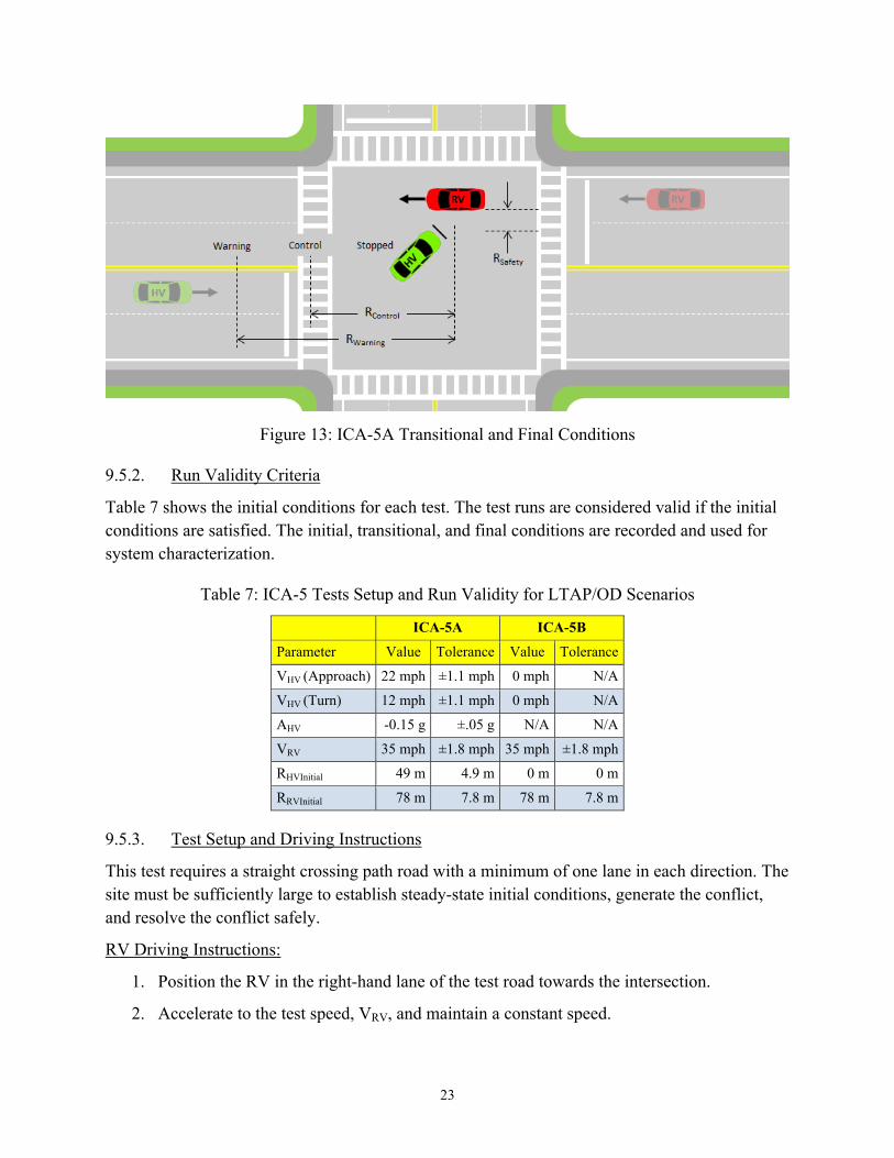
23
Figure 13: ICA-5A Transitional and Final Conditions
9.5.2. Run Validity Criteria
Table 7 shows the initial conditions for each test. The test runs are considered valid if the initial conditions are satisfied. The initial, transitional, and final conditions are recorded and used for system characterization.
Table 7: ICA-5 Tests Setup and Run Validity for LTAP/OD Scenarios
ICA-5A ICA-5B
Parameter Value Tolerance Value Tolerance
VHV (Approach) 22 mph ±1.1 mph 0 mph N/A
VHV (Turn) 12 mph ±1.1 mph 0 mph N/A
AHV -0.15 g ±.05 g N/A N/A
VRV 35 mph ±1.8 mph 35 mph ±1.8 mph
RHVInitial 49 m 4.9 m 0 m 0 m
RRVInitial 78 m 7.8 m 78 m 7.8 m
9.5.3. Test Setup and Driving Instructions
This test requires a straight crossing path road with a minimum of one lane in each direction. The site must be sufficiently large to establish steady-state initial conditions, generate the conflict, and resolve the conflict safely.
RV Driving Instructions:
1. Position the RV in the right-hand lane of the test road towards the intersection.
2. Accelerate to the test speed, VRV, and maintain a constant speed.

24
3. Cross through the intersection.
4. Stop the RV after clearing the intersection.
HV Driving Instructions:
1. Position the HV in the left-hand lane on a road opposite the RV.
2. ICA-5A: Accelerate to the test speed, VHV, and maintain constant speed. ICA-5B: Drive the HV to the stop line and wait until the RV approaches.
3. The HV and the RV drivers should communicate such that vehicles arrive at the intersection at the same time.
4. Activate the left-turn signal, begin slowing to the target speed using the throttle and/or brakes, and start turning left into the path of the RV.
5. Maintain a constant accelerator pedal position and speed until an ICA warning, then apply the brakes to bring the HV to a stop.
6. If the vehicle has an ICA system with automatic control, ignore the expected ICA warning and maintain a constant accelerator pedal position and speed.
7. Maintain a constant accelerator pedal position when the ICA automatic control activates.
8. When the HV comes to a full stop, apply the brakes.
At any time during the test, if the HV driver determines that the test conditions are unsafe, the HV driver manually avoids the collision.
10. PROCEDURES FOR NO-ACTION TEST SCENARIOS
The purpose of the no-action test scenarios is to verify that the HV suppresses all ICA warnings and control actions in test scenarios where there is no threat of collision with the RV.
Table 8 lists the five no-action test scenarios.

25
Table 8: Summary of No-Action ICA Test Scenarios
Type Test No. Test Description
No-Action ICA-6 Straight Crossing Paths with stopping RV
No-Action ICA-7 SCP with stopping HV
No-Action ICA-8 Left Turn across Path/Opposite Direction with stopping RV
No-Action ICA-9 Both HV and RV Turning Right
No-Action ICA-10 HV Turning Right, RV Continuing Straight
10.1. ICA-6: SCP, RV Slowing to Stop
This test verifies that the ICA system does not issue warnings or initiate automatic control when the HV and RV simultaneously approach an intersection and no collision threat is present. This test especially verifies the ability of the ICA system to accurately identify braking cross-path targets at a flat, straight intersection and not generate any countermeasure actions. This test is run at one set of initial conditions.
10.1.1. Test Overview
The test begins with HV traveling on straight, flat road at constant speed toward an intersection. In the crossing path ahead of the HV, the RV is traveling on a straight, flat road slowing to stop before the intersection as shown in Figure 14. The HV should attain the initial test speed of VHV at least 6 seconds from the intersection, measured by the corresponding range between HV and the intersection. The HV continues at constant speed towards the intersection, without cruise control, and without the test driver manually activating the brakes. The RV should attain the initial test speed of VRV at least 6 seconds from the intersection, then brake manually to a stop and does not enter the intersection.

26
Figure 14: ICA-6 Test Initial Conditions
Figure 15 illustrates the transitional and final conditions of the test. As the HV and the RV approach the intersection, the ICA system should not trigger any countermeasure action. The HV continues through the intersection past the RV and comes to a stop.

27
Figure 15: ICA-6 Transitional and Final Conditions
10.1.2. Run Validity Criteria
Table 9 shows the initial conditions for the test. The test runs are considered valid if the initial conditions are satisfied.
Table 9: ICA-6 Test Setup and Run Validity for SCP With Slowing RV Scenario
Parameter Value Tolerance
VHV 35 mph ±1.8 mph
VRV 35 mph ±1.8 mph
ARV -0.15 g ±0.1 g
10.1.3. Test Setup and Driving Instructions
This test requires a straight crossing path road with a minimum of two lanes in each direction. The site must be sufficiently large to establish steady-state initial conditions, generate the conflict, and resolve the conflict safely.

28
RV Driving Instructions:
1. Position the RV in the right-hand lane of the test road towards the intersection.
2. Accelerate to the test speed, VRV.
3. Slow to a stop before entering the intersection.
HV Driving Instructions:
1. Position the HV in the right-hand lane on a road perpendicular to the RV.
2. Accelerate to the test speed, VHV, and maintain constant speed.
3. The HV and the RV drivers should communicate such that vehicles arrive at the intersection at the same time.
4. Maintain constant speed and continue through the intersection.
5. After clearing the intersection, apply the brakes.
At any time during the test, if the HV driver determines that the test conditions are unsafe, the HV driver manually avoids the collision.
10.2. ICA-7: SCP, HV Slowing to Stop
This test verifies that the ICA system does not issue warnings or initiate automatic control when the HV and RV simultaneously approach an intersection and no collision threat is present. This test especially verifies the ability of the ICA system to accurately identify cross-path targets at a flat, straight intersection while the HV is braking and not generate any countermeasure actions. This test is run at one set of initial conditions.
10.2.1. Test Overview
The test begins with HV traveling on straight, flat road before braking to a stop at an intersection. In the crossing path ahead of the HV, the RV is traveling on a straight, flat road at constant speed toward the intersection, as shown in Figure 16. The HV should attain the initial test speed of VHV at least 6 seconds from the intersection, measured by the corresponding range between HV and the intersection. The HV then brakes manually to a stop and does not enter the intersection. The RV should attain the initial test speed of VRV at least 6 seconds from the intersection.

29
Figure 16: ICA-7 Test Initial Conditions
Figure 17 illustrates the transitional and final conditions of the test. As the HV and the RV approach the intersection, the ICA system should not trigger any countermeasure action. The RV continues through the intersection past the HV and comes to a stop.

30
Figure 17: ICA-7 Transitional and Final Conditions
10.2.2. Run Validity Criteria
Table 10 shows the initial conditions for the test. The test runs are considered valid if the initial conditions are satisfied.
Table 10: ICA-7 Test Setup and Run Validity for SCP With Stopping HV Scenario
Parameter Value Tolerance
VHV 35 mph ±1.8 mph
VRV 35 mph ±1.8 mph
AHV -0.15 g ±0.1 g
10.2.3. Test Setup and Driving Instructions
This test requires a straight crossing path road with a minimum of one lane in each direction. The site must be sufficiently large to establish steady-state initial conditions, generate the conflict, and resolve the conflict safely.

31
RV Driving Instructions:
1. Position the RV in the right-hand lane of the test road towards the intersection.
2. Accelerate to the test speed, VRV, and maintain a constant speed.
3. Cross through the intersection.
4. Stop the RV after clearing the intersection.
HV Driving Instructions:
1. Position the HV in the right-hand lane on a road perpendicular to the RV.
2. Accelerate to the test speed, VHV, before slowing to a complete stop short of the intersection.
3. The HV and the RV drivers should communicate such that vehicles arrive at the intersection at the same time.
4. Slow to a stop before entering the intersection.
At any time during the test, if the HV driver determines that the test conditions are unsafe, the HV driver manually avoids the collision.
10.3. ICA-8: LTAP/OD, RV Slowing to Stop
This test verifies that the ICA system does not issue warnings or initiate automatic control when the HV and RV simultaneously approach an intersection and no collision threat is present. This test especially verifies the ability of the ICA system to accurately identify braking opposite-direction targets at a flat, straight intersection and not generate any countermeasure actions. This test is run at one set of initial conditions.
10.3.1. Test Overview
The test begins with HV traveling on straight, flat road at constant speed toward an intersection intending to make a left turn. In the opposite lane ahead of the HV, the RV is traveling on a straight, flat road toward the intersection as shown in Figure 18. The HV should attain the initial test speed of VHV at least 6 seconds from the intersection, measured by the corresponding range between HV and the intersection. The RV should attain the initial test speed of VRV at least 6 seconds from the intersection, then brake manually to a stop and does not enter the intersection.

32
Figure 18: ICA-8 Test Initial Conditions
Figure 19 illustrates the transitional and final conditions of the test. As the HV and the RV approach the intersection, the ICA system should not trigger any countermeasure action. The HV executes a left turn through the intersection and comes to a stop.
Figure 19: ICA-8 Transitional and Final Conditions
10.3.2. Run Validity Criteria
Table 11 shows the initial conditions for the test. The test runs are considered valid if the initial conditions are satisfied.

33
Table 11: ICA-8 Test Setup and Run Validity for LTAP/OD With Slowing RV Scenario
Parameter Value Tolerance
VHV 25 mph ±1.3 mph
VRV 25 mph ±1.3 mph
ARV -0.15 g ±0.1 g
10.3.3. Test Setup and Driving Instructions
This test requires a straight crossing path road with a minimum of one lane in each direction. The site must be sufficiently large to establish steady-state initial conditions, generate the conflict, and resolve the conflict safely.
RV Driving Instructions:
1. Position the RV in the right-hand lane of the test road towards the intersection.
2. Accelerate to the test speed, VRV.
3. Slow to a stop before entering the intersection.
HV Driving Instructions:
1. Position the HV in the left-hand lane on a road opposite to the RV.
2. Accelerate to the test speed, VHV, maintain constant speed, and activate the left-turn signal.
3. The HV and the RV drivers should communicate such that vehicles arrive at the intersection at the same time.
4. Maintain constant speed and continue through the intersection.
5. After clearing the intersection, apply the brakes.
At any time during the test, if the HV driver determines that the test conditions are unsafe, the HV driver manually avoids the collision.
10.4. ICA-9: Both HV and RV Turning Right
This test verifies that the ICA system does not issue warnings or initiate automatic control when the HV and RV simultaneously approach an intersection, both intending to turn right without any threat of collision. This test especially verifies the ability of the ICA system to accurately identify the intent of the two vehicles to turn right (as evidenced within the BSM part II “turn signal” information of HV and RV) at a flat, straight intersection and not generate any countermeasure actions. This test is run at one set of initial conditions.

34
10.4.1. Test Overview
The test begins with HV traveling on straight, flat road at constant speed toward an intersection intending to make a right turn with the right-turn signal activated. In the crossing lane ahead of the HV, the RV is traveling on a straight, flat road at constant speed toward the intersection, as shown in Figure 20, also intending and signaling a right turn. The intended paths of the HV and RV do not cross. The HV should attain the initial test speed of VHV at least 6 seconds from the intersection, measured by the corresponding range between HV and the intersection. The RV should attain the initial test speed of VRV at least 6 seconds from the intersection.
Figure 20: ICA-9 Test Initial Conditions
Figure 21 illustrates the transitional and final conditions of the test. As the HV and the RV approach the intersection, the ICA system should not trigger any countermeasure action. The HV and RV both execute right turns through the intersection and come to a stop.

35
Figure 21: ICA-9 Transitional and Final Conditions
10.4.2. Run Validity Criteria
Table 12 shows the initial conditions for the test. The test runs are considered valid if the initial conditions are satisfied.
Table 12: ICA-9 Test Setup and Run Validity for HV and RV Turning Right
Parameter Value Tolerance
VHV 25 mph ±1.3 mph
VRV 25 mph ±1.3 mph
10.4.3. Test Setup and Driving Instructions
This test requires a straight crossing path road with a minimum of one lane in each direction. The site must be sufficiently large to establish steady-state initial conditions, generate the conflict, and resolve the conflict safely.
RV Driving Instructions:
1. Position the RV in the right-hand lane of the test road towards the intersection.
2. Accelerate to the test speed, VRV, activate the right-turn signal, and maintain a constant speed.

36
3. Slow to the turn speed (any speed between 12 and 22 mph) then turn right at the intersection.
HV Driving Instructions:
1. Position the HV in the right-hand lane on a road perpendicular to the RV.
2. The HV and the RV drivers should communicate such that vehicles arrive at the intersection at the same time.
3. Accelerate to the test speed, VHV, activate the right-turn signal, and maintain constant speed.
4. Slow to the turn speed (any speed between 12 and 22 mph) then turn right at the intersection.
5. After clearing the intersection, apply the brakes.
At any time during the test, if the HV driver determines that the test conditions are unsafe, the HV driver manually avoids the collision.
10.5. ICA-10: HV Turning Right, RV Continuing Straight
This test verifies that the ICA system does not issue warnings or initiate automatic control when the HV and RV simultaneously approach an intersection, HV turning right and RV going straight, and both vehicles traveling in separate lanes without any threat of collision threat. This test especially verifies the ability of the ICA system to accurately identify the intent of the HV to turn before crossing into the path of the RV at a flat, straight intersection and not generate any countermeasure actions. This test is run at one set of initial conditions.
10.5.1. Test Overview
The test begins with HV traveling on straight, flat road at constant speed toward an intersection intending to make a right turn. In the right perpendicular lane ahead of the HV, the RV is traveling on a straight, flat road at constant speed toward the intersection, as shown in Figure 22. The HV should attain the initial test speed of VHV at least 6 seconds from the intersection, measured by the corresponding range between HV and the intersection. The RV should attain the initial test speed of VRV at least 6 seconds from the intersection.

37
Figure 22: ICA-10 Test Initial Conditions
Figure 23 illustrates the transitional and final conditions of the test. As the HV and the RV approach the intersection, the ICA system should not trigger any countermeasure action. The HV executes a right turn through the intersection and comes to a stop.

38
Figure 23: ICA-10 Transitional and Final Conditions
10.5.2. Run Validity Criteria
Table 13 shows the initial conditions for the test. The test runs are considered valid if the initial conditions are satisfied.
Table 13: ICA-10 Test Setup and Run Validity for HV Turning Right, RV Continuing Straight
Parameter Value Tolerance
VHV 25 mph ±1.3 mph
VRV 35 mph ±1.8 mph
10.5.3. Test Setup and Driving Instructions
This test requires a straight crossing path road with a minimum of one lane in each direction. The site must be sufficiently large to establish steady-state initial conditions, generate the conflict, and resolve the conflict safely.
RV Driving Instructions:
1. Position the RV in the right-hand lane of the test road towards the intersection.
2. Accelerate to the test speed, VRV, and maintain a constant speed.
3. Cross through the intersection.
4. Stop the RV after clearing the intersection.

39
HV Driving Instructions:
1. Position the HV in the right-hand lane on a road perpendicular to the RV.
2. Accelerate to the test speed, VHV, and maintain constant speed.
3. The HV and the RV drivers should communicate such that vehicles arrive at the intersection at the same time.
4. Activate the right-turn signal, slow to the turning speed (any speed between 12 and 22 mph), and turn right at the intersection.
5. After clearing the intersection, apply the brakes.
At any time during the test, if the HV driver determines that the test conditions are unsafe, the HV driver manually avoids the collision.
11. CONCLUSION
This report described test procedures to characterize the performance of prototype ICA systems based on V2V communications and relative positioning between the HV and RV. These procedures were initially applied to a number of prototype OEM systems on a closed-course test track, as part of Track 4 of the Connected Vehicle Safety program by NHTSA and the Intelligent Transportation Systems Joint Program Office. Based on the experience gained and lessons learned from these trials at the test track, these characterization test procedures were refined as described in this report. This test description delineated the test data variables, instrumentation, validity criteria, safety requirements, and driving instructions.
This report presented a set of crossing-path crash-imminent test scenarios (i.e., countermeasure-action scenarios) to collect data on the crash avoidance capability of the ICA systems under various initial conditions. These scenarios represented the most common crossing-path pre-crash scenarios reported in national crash databases. In addition, this report provided another set of test scenarios to collect data on the ability of the ICA systems to ignore benign driving scenarios (i.e., no-countermeasure-action scenarios).
The application of these characterization test procedures will enable data collection to better understand the capability of prototype ICA systems and help estimate their potential safety benefits. These test procedures did not incorporate pass-fail criteria that judge how well the prototype ICA systems meet some pre-determined performance requirements. Moreover, these test procedures as described in the report provided insight into ways by which V2V-based ICA applications may be evaluated on the test track. Finally, these procedures may be used by NHTSA as a basis for future system testing as part of any rulemaking activity regarding V2V-based ICA products.

40
12. REFERENCES
[1] National Highway Traffic Safety Administration and Research and Innovative Technology Administration. (2011, October). USDOT Connected Vehicle Research Program Vehicle-to-Vehicle Safety Application Research Plan (Report No. DOT HS 811 373). Washington, DC: Authors.
[2] Harding, J., Powell, G., Yoon, R., Fikentscher, J., Doyle, C., Sade, D., … & Wang, J. (2014, August). Vehicle-to-vehicle communications: Readiness of V2V technology for application (Report No. DOT HS 812 014) Washington, DC: National Highway Traffic Safety Administration.
[3] Ahmed-Zaid, F., Bai, F., Bai, S., Basnayake, C., Bellur, B., Brovold, S., … & VanSickle, S. (2011, September).. (2010, May). Vehicle Safety Communications – Applications (VSC-A). (Final Report. Report No. DOT HS 811 492A). Washington, DC: National Highway Traffic Safety Administration.
[4] Crash Avoidance Metrics Partnership. (2011, October 10). CAMP VSC3 – Model Deployment Safety Device DSRC BSM Communication Minimum Performance Requirements, Revision 11. (Internal document). Washington, DC: National Highway Traffic Safety Administration.
[5] Oxford Technical Solutions. (n.d.). RT Inertial and GNSS Measurement Systems User Manual (Revision 140611) Oxfordshire, UK: Author.

41
Appendix A: Transportation Research Center Test Areas

42

43
Appendix B: High-Level Functional Block Diagram of In-Vehicle Test Equipment
Figure 24: HV Test Equipment

44
Figure 25: RV Test Equipment

45
Appendix C: Track 4 DAS Data Requirements
Block No Parameters
In-Host V
ehicle Sensors
1 Longitudinal velocity 2 Lateral velocity 3 Heading 4 Longitudinal acceleration 5 Lateral acceleration 6 Accelerator pedal state 7 Throttle position 8 Brake pedal state 9 Brake applied status
10 Yaw rate 11 Steering angle 12 Turn signal state 13 Transmission state 14 ABS state 15 Traction control state 16 Electronic stability control state 17 Cruise control state
ICA
Controller
18 BSM of host vehicle 19 BSM of all remote vehicles 20 ICA system status 21 Predicted path of host vehicle 22 Target ID for all remote vehicles 23 Target status for all remote vehicles 24 Target range for all remote vehicles 25 Target range rate for all remote vehicles 26 Target longitudinal acceleration for all remote vehicles 27 Target yaw rate for all remote vehicles 28 Threat level (alert and/or control) 29 Transmission control messages 30 Throttle control messages 31 Brake control messages 32 DVI messages

DOT HS 812 223 December 2015
11844-122115-v2