characterization of the mobility of fc riia in primary ... · pdf filecharacterization of the...
TRANSCRIPT

Characterization of the Mobility of FcγRIIa in Primary Human Macrophages
by
Yoav Farkash
A thesis submitted in conformity with the requirementsfor the degree of Master of Biochemistry
Department of BiochemistryUniversity of Toronto
© Copyright by Yoav Farkash 2010

Characterization of the Mobility of FcγRIIa in Primary Human
Macrophages
Yoav Farkash
Masters of Biochemistry
Department of BiochemistryUniversity of Toronto
2010
AbstractFcγ receptor-mediated phagocytosis is an active process requiring receptor clustering as a signal
initiation event. The mechanisms controlling Fcγ receptor clustering are unknown, as are the
parameters governing the receptor lateral mobility in the plasma membrane. This work
investigated the lateral mobility of Fcγ receptor IIa in resting primary human macrophages using
single-molecule tracking methodology. In the absence of ligands, the receptor was found to exist
mostly as a monomeric species. Detailed receptor dynamics revealed the existence of two
receptor populations: one that was mobile, the other confined. The actin cytoskeleton was shown
to be important for receptor confinement but did not affect receptor diffusion. Such findings are
important in understanding the mechanisms for receptor clustering and signal initiation in
phagocytosis.
ii

Acknowledgments
First, I would like to thank my supervisor, Sergio Grinstein, for his support and endless
patience during my time in the lab. Your enthusiasm is inspiring and I must say that the most
optimistic part of my week was the evening after our meeting, when I would get excited about
the next steps. I would also like to thank my committee members, James Booth and John
Parkinson, for your time and support along the way.
I would like to thank the members of the Grinstein lab (the Grinsteins), past and present, for
the incredible encouragement, support, friendship and for being simply the best company one can
hope for. Life will be hard without you guys and the unique Grinstein humour. Special thanks go
to Dave Mason, Kassidy Huynh, and Ben Steinberg, who supported me outside the lab as much
as in. I hope our friendship will last for years to come.
A special mention goes to my family for their encouragement from afar. Your patience over
the years was beyond what I expected and I am hoping to reunite at the earliest time.
Last but not least, I would like to thank my better half, Denise, for holding me afloat
throughout the last year, for your help, support, encouragement and for keeping a bright view
when times got dark.
iii

Table of Contents
Abstract...................................................................................................................................ii
Acknowledgments..................................................................................................................iii
Table of Contents...................................................................................................................iv
Data attribution.....................................................................................................................vii
List of abbreviations............................................................................................................viii
List of Tables...........................................................................................................................x
List of Figures........................................................................................................................xi
Chapter 1: Characterization of FcγRIIa Diffusion in human macrophages............................1
1 Introduction...........................................................................................................................1
1.1 Biological system..........................................................................................................1
1.1.1 Macrophages in the Innate and adaptive immune responses..............................1
1.1.2 Origin of Macrophages.......................................................................................3
1.1.3 Phagocytosis.......................................................................................................4
1.1.3.1 General mechanism of phagocytosis....................................................5
1.1.3.2 Receptors and Ligands ........................................................................6
1.1.4 Fc receptors.........................................................................................................7
1.1.4.1 Structure of Fc Receptors.....................................................................8
1.1.5 FcγIIa receptor..................................................................................................10
1.1.5.1 Ligand................................................................................................11
1.1.5.2 Signaling............................................................................................13
1.1.5.3 Receptor engagement: a key unresolved issue in phagocytosis.........18
1.2 Molecular diffusion.....................................................................................................21
1.2.1 Overview...........................................................................................................21
iv

1.2.2 MSD calculation ..............................................................................................22
1.2.3 Basic MSD analysis..........................................................................................23
1.2.4 Diffusion in membranes....................................................................................25
1.2.4.1 Model membrane experiments...........................................................25
1.2.4.2 Experiments using cellular membranes.............................................26
1.2.4.3 Hop diffusion.....................................................................................28
1.3 Single-molecule spectroscopy.....................................................................................30
1.3.1 Advantages of Single-Molecule approach........................................................30
1.3.2 The Setup of SPT experiments..........................................................................32
1.3.2.1 Detection............................................................................................32
1.3.2.2 Tracking.............................................................................................39
1.3.2.3 Data treatment....................................................................................42
2 Methods...............................................................................................................................43
2.1 Cells.............................................................................................................................43
2.2 Antibodies...................................................................................................................43
2.3 Labeling.......................................................................................................................44
2.4 Drug treatments...........................................................................................................44
2.5 Single molecule system specifics................................................................................45
2.5.1 Acquisition setup...............................................................................................45
2.5.2 Detection...........................................................................................................45
2.5.3 Tracking specifics.............................................................................................48
2.5.4 Diffusion analysis.............................................................................................51
3 Results.................................................................................................................................52
3.1 Calibration slides.........................................................................................................52
3.1.1 Detection of single molecules, determination of minimal quanta....................52
3.1.2 Positional accuracy...........................................................................................61
v

3.2 FcγRIIa is monomeric.................................................................................................64
3.2.1 Saturation experiments......................................................................................66
3.2.2 Photobleaching experiments.............................................................................69
3.3 Diffusion in basal state................................................................................................71
3.4 Involvement of the cytoskeleton.................................................................................89
4 Discussion...........................................................................................................................94
4.1 Aggregation state of FcγRIIa......................................................................................94
4.2 Diffusion of FcγRIIa in the basal state........................................................................99
4.3 Future Direction........................................................................................................109
vi

Data attribution
Data in Table 8 was obtained by Dr. Ron Flannagan, currently a postdoctoral fellow in the
laboratory of Dr. Sergio Grinstein (Hospital for Sick Children). Figure 3 is based on a figure
originally made by Dr. Greg Fairn, currently a postdoctoral fellow in Dr. Grinstein's laboratory.
Data in all other figures was obtained by myself.
vii

List of abbreviations
ABP actin-binding proteinARF ADP-ribosylation factorBLNK B cell linker proteinBtk Bruton tyrosine kinaseCCD Charge-Coupled DeviceCFP cyan fluorescent proteinCrkII CT10 regulator of kinase isoform IIDAG diacylglycerolD diffusion coefficientEGF epidermal growth factorFc Fragment, crystallizable, of the antibody moleculeFcRs Fc receptors FcγR Fc receptors of the γ subclassFPS Frames Per SecondGAP GTPase-activating proteinGEF guanine nucleotide-exchange factorGFP green fluorescent proteinGPCR G protein-coupled receptorHPMI RPMI-1640, HEPES bufferedITAM immunoreceptor tyrosine-based activation motifITIM immunoreceptor tyrosine-based inhibitory motifIP3 inositol trisphosphateLAT linker of activation of T cellLDL low-density lipoproteinLPS lipopolysaccharideMAPK mitogen-activated protein kinaseMSD mean square displacementNA numerical aperturep40Phox 40-kDa subunit of the NADPH oxidasePH pleckstrin homologyPI phosphatidylinositolPI(3)P phosphatidylinositol-3-phosphatePI(4)P phosphatidylinositol-4-phosphate PI(5)P phosphatidylinositol-5-phosphatePI(3,4)P2 phosphatidylinositol-3,4-bisphosphatePI(4,5)P2 phosphatidylinositol-4,5-bisphosphatePI(3,5)P2 phosphatidylinositol-3,5-bisphosphatePIP3 phosphatidylinositol-3,4,5-trisphosphatePI3K phosphatidylinositol 3-kinasePIPKI type I phosphatidylinositide phosphate kinasesPIPKII type II phosphatidylinositide phosphate kinasesPKC Protein Kinase CPLA2 phospholipase A2
viii

PLC phospholipase CPLD phospholipase DPRR pattern-recognition receptorPSF point spread functionPTEN phosphatase and tensin homolog deleted on chromosome 10QD (xxx) quantum dot (of xxx wavelength emission)SFK Src Family KinaseSH2 Src homology 2SH3 Src homology 3SHIP SH2 domain-containing inositol 5-phosphataseSNR signal-to-noise ratioSPT single-particle trackingSYK Spleen tyrosine kinaseTIRF total internal reflection fluorescenceTLR Toll-like receptorWASP Wiskott-Aldrich Syndrome proteinWAVE WASP-family verprolin homologous protein
ix

List of Tables
Table 1: Relative affinities of IgG subclasses to FcγRs.................................................................13
Table 2: Detection parameters........................................................................................................47
Table 3: Linking parameters..........................................................................................................49
Table 4: Saturation analysis data....................................................................................................65
Table 5: Diffusion characteristics of FcγRIIa................................................................................72
Table 6: Effect of latrunculin B on the diffusion coefficient of FcγRIIa.......................................85
Table 7: Parameters of immobilized particles and FcγRIIa confined tracks.................................95
Table 8: Effect of actin perturbation on particle binding and receptor mobility............................99
x

List of Figures
Figure 1: Common members of the Fc receptor family. .................................................................9
Figure 2: Schematic of the antibody molecule and digestion products. .......................................12
Figure 3: FcγR signaling. ..............................................................................................................20
Figure 4: Theoretical MSD plots. .................................................................................................24
Figure 5: Airy discs and resolution. ..............................................................................................34
Figure 6: Schematic of single-molecule detection.........................................................................35
Figure 7: Detected features overlaid on top of DyLight of raw image. ........................................54
Figure 8: Intensity of single DyLight molecule over time, long track. .........................................55
Figure 9: Intensity of single DyLight molecule over time, short track. ........................................56
Figure 10: Distribution of feature intensities with fitted Gaussians. ............................................57
Figure 11: Detected features overlaid on top of QDs raw image. ................................................58
Figure 12: Intensity of a single QD over time. ............................................................................59
Figure 13: Positional accuracy distribution, DyLight. ..................................................................61
Figure 14: Positional accuracy distribution, QD. ..........................................................................61
Figure 15: Effect of feature intensity on its positional accuracy. ..................................................62
Figure 16: Schematic of a saturation experiment. .........................................................................64
Figure 17: Sample data of a calibration slide. ...............................................................................66
Figure 18: Sample data for a saturation experiment. ...................................................................67
Figure 19: Results of representative photobleaching experiment. ................................................69
Figure 20: Tracks overlaid over QD raw movie. .........................................................................73
Figure 21: QD tracks colored by diffusion mode. ........................................................................74
Figure 22: Percentage breakdown of diffusion mode, Cy3 tracks. ...............................................75
Figure 23: Percentage breakdown of diffusion mode, QD tracks. ................................................76
Figure 24: Mean diffusion coefficients based on track class, Cy3 tracks. ....................................77
Figure 25: Mean diffusion coefficients based on track class, QD tracks. .....................................78
Figure 26: Mean confinement region, Cy3 confined tracks. .........................................................79
Figure 27: Mean confinement region, QD confined tracks. .........................................................80
Figure 28: Confinement region is not affected by positional accuracy: .......................................81
Figure 29: Effect of latrunculin B on diffusion mode....................................................................84
xi

Figure 30: Effect of latrunculin B on the diffusion coefficient. ....................................................85
Figure 31: Latrunculin B does not affect the confinement region of confined tracks. .................86
Figure 32: Immobility due to confinement vs. tethering. .............................................................94
Figure 33: Comparison of immobile QDs and tracked QD-labeled FcγRIIa. .............................96
xii

1
Chapter 1: Characterization of FcγRIIa Diffusion in human macrophages
1 IntroductionThis thesis explores the molecular motion of the phagocytic receptor FcγRIIa. The introduction
covers three topics. It begins with an introduction to the biological system from the cell type to
the receptor used in the project. The second section of the introduction explores molecular
diffusion in general, from the definition of diffusion through different theories regarding
diffusion in cell membranes, to the current models used in the literature. The final section of the
introduction is more technical and explains the concepts of single-molecule microscopy. As this
technology is relatively new, significant effort was devoted to understanding the technological
pros and cons, the software design and the analysis parameters, and to developing an automation
code. The general concepts of single-particle microscopy experiments are discussed in the third
section of the introduction, while the specific software parameters are covered in the Methods
section.
1.1 Biological system1.1.1 Macrophages in the Innate and adaptive immune responses
The immune response in mammals is generally considered to have two 'arms' – the innate
and the adaptive immune components. The two differ in the time scale in which they operate, the
way they identify threats, the response they mount to those threats and, to some extent, the cell
types utilized. However, there is a tight integration and inter-relationship between the two arms.
At the heart of the interface between the two lies the process of phagocytosis (receptor-mediated

2
uptake of extracellular particles into a cellular compartment, discussed in depth later), which
takes part in both the innate and adaptive immune response, with some noticeable differences.
The innate immune response is considered a 'first line of defense', equipped to recognize and
respond to general threats. The phagocytic cell types participating in the innate immune response
are dendritic cells (DCs), macrophages and neutrophils, while non-phagocytic cells include
natural killer (NK) cells, mast cells, eosinophils and basophils. The major non-cellular
component of the innate immune response is the complement system. The adaptive immune
response, on the other hand, is a second, later response geared for detection and destruction of
specific pathogens and antigens. The major players are T- and B-lymphocytes as well as
macrophages. The adaptive response requires priming by the innate response via the process of
'antigen-presentation': phagocytosed pathogens are processed and presented on the surface of the
phagocytic cell, such that T cells can recognize the specific peptide presented. The ensuing
sequence of events culminates in the activation of B cells, the production of antibodies, efficient
pathogen recognition and elimination as well as immunological 'memory' which allows the
organism to better react to identical future threats.
The phagocytic cells mentioned above bear more than one phagocytic receptor, hence they
are capable of phagocytosis in response to different stimuli. At the early stages of an immune
response a set of receptors known as Pattern-Recognition Receptors (PRRs) are the major ones
utilized. PRRs recognize molecular patterns that have been evolutionarily conserved among
different pathogens, such as components of the cell wall, thus allowing for a general mechanism
of pathogen recognition. Examples of PRRs that are capable of mediating phagocytosis are
scavenger receptor A (which recognizes LPS, LTA, bacterial DNA) and the mannose receptor12,
among others. A second mechanism at play during the early stages of infection is the
complement system, comprised of a number of plasma proteins with the ability to bind bacterial
3
external surfaces. Once bound, a series of enzymatic reactions at the site of attachment leads to
an inflammatory response, pathogen destruction via pore-formation at the pathogen membrane
and priming of the pathogen for phagocytosis via complement receptors present on phagocytic
cells3. Combined, PRR- and complement-mediated phagocytosis are the major phagocytic
mechanisms in the early immune response leading to antigen presentation
Once activated in response to a specific peptide, the adaptive immune response will engage
in a complex cascade of events leading to the production and release of antibodies by B cells.
Antibodies will be discussed in depth later, but briefly, they are protein molecules capable of
identifying specific, not general, molecular patterns and marking the particle bearing the pattern
for immune targeting, based on the antibody type. One such reaction is phagocytosis of antibody-
opsonized particles. Since antibodies are plentiful and can recognize a virtually infinite number
of patterns, clearance of targeted particles by macrophages is among the most efficient
mechanisms for fighting infections. Combined, phagocytosis dependent on PPRs or antibodies
and the ability to process and present antigens places macrophages at a critical junction in the
immune response.
1.1.2 Origin of Macrophages
Macrophages, like all other immune cells, arise from hematopoeitic stem cells, yet not all
macrophages follow the same developmental pathway. As a fully differentiated group they
encompass different cells, all of which are able to engage in the process of phagocytosis. One
distinction exists between tissue-resident macrophages and circulating ones. Tissue-resident
macrophages are specialized macrophages that remain associated with a specific tissue and
perform specific tasks therein. Examples of such cells are Kupffer cells in the liver, microglia in
the brain and alveolar macrophages in the lungs. Those macrophages develop from immature

4
macrophage progenitor cells, an earlier stage than the promonoblast progenitor cell, and are
long-lived with the ability for self-renewal4,5 . Circulating macrophages are not literally
'circulating', but colonize infected tissues in response to chemokines secreted from cells at the
site of infection. The precursor circulating cells are monocytes, which are abundant in the
bloodstream and differentiate into macrophages upon stimulation and colonization of the infected
tissue. Unstimulated monocytes and their macrophage progeny are short-lived, with a half life of
3 and 12 days, respectively. While the mechanisms of phagocytosis are common among different
macrophages, this project only investigates monocyte-derived macrophages and not tissue-
resident macrophages.
1.1.3 Phagocytosis
Phagocytosis is traditionally defined as the receptor-mediated uptake of particles bigger than
0.5µm.Within seconds after engagement of the particle by the relevant receptors, membrane
protrusions termed 'pseudopods' are extended around the particle, culminating in fusion of the
protrusions to create a fully sealed compartment, termed a phagosome, around the particle.
Following the creation of the sealed phagosome, a maturation process ensues during which the
phagosome membrane, as well as its content, are modified from primarily a plasmalemma and
extracellular content to highly specialized ones designed for microbicidal function. The
maturation process involves multiple interactions with intracellular compartments of the
endocytic pathway and in many ways follows a similar fate, culminating with the creation of the
phago-lysosome with its acidic pH and degradative capacities.
As mentioned above, multiple receptors are capable of initiating phagocytosis. While the
end product of the process is similar, some differences exist. One noticeable example is the
morphology of the process. Complement-mediated phagocytosis was reported to proceed via a

5
strikingly different morphological process, with the particle sinking into the macrophage rather
than being engulfed by pseudopods6. While this morphological observation has been contested7,
there is no doubt that engagement of different phagocytic receptors transmits different signals to
achieve a similar end (formation of a phagocytic vacuole) in all cases. A second difference lies
with the nature of the downstream immune response. While Fc-mediated phagocytosis is
accompanied by an inflammatory response, PS-mediated phagocytosis of apoptotic cells, for
example, results in an anti-inflammatory one. Such differences lie in the specific signaling
downstream of the phagocytic receptors.
Phagocytosis is a distinct internalization pathway. While it shares many of the endocytic
pathway maturation events it is initiated in a completely different fashion from any of the
endocytic pathways. Similarly, it shares some characteristics with macro-pinocytosis8 and a
similar fate to autophagy. Nevertheless, events throughout the process are unique and while
comparisons with other internalization processes are sometimes used, they each represent a
unique research field.
1.1.3.1 General mechanisms of phagocytosis
Unlike many signaling pathways, the signal for initiation of phagocytosis is not simply the
binding of ligand to the receptor. In order to initiate phagocytosis, clustering of numerous
receptors is required. Clustering is achieved by virtue of the phagocytic target being coated by
many phagocytic ligands, be it antibodies, complement or another ligand. Once the pathogen is
in close proximity to the phagocyte surface, binding can occur between multiple ligands and
receptors. Since the area in close proximity is usually small (relative to the cell size) clustering of
multiple receptors will take place and serves as the primary upstream event that initiates
phagocytosis.
6
Upon receptor clustering a cascade of signaling events ensues (discussed in detail below),
leading to local remodeling of the plasma membrane lipids, recruitment of actin and other
cytoskeletal proteins, the projection of membrane extensions around the particle and finally the
closure of the phagosome, which becomes an isolated compartment inside the phagocyte.
1.1.3.2 Receptors and Ligands
A number of different ligands can initiate phagocytosis. These include antibodies,
complement, PAMPs in the case of pathogen-directed phagocytosis and phosphatidyl-serine (PS)
in the case of host-cell phagocytosis. Complement and antibodies are termed 'opsonins', host-
produced molecules that bind and target foreign particles for phagocytosis. PAMPs and PS, on
the other hand, are integral components of the phagocytic target.
The phagocytic receptors that bind PAMPs and PS are mostly members of the scavenger-
receptors (SR) family. In the case of PAMPs, an array of scavenger receptors from different
classes is capable of recognizing numerous patterns on the surface of pathogens. A few notable
examples are the recognition of lipopolysaccharide (LPS; endotoxin), a major component of the
outer cell wall of gram-negative bacteria, by SR-A1 and -B1; β-Glucan, expressed on the surface
of yeast is recognized by Dectin-12 and lipoteichoic acid (LTA), a component of gram-positive
bacteria is recognized by CD14 as well SR-A1. PS-mediated phagocytosis is also orchestrated
via a plethora of scavenger receptors. In this case, many adaptor molecules (opsonins) are
involved in binding PS and bridging its interaction with the phagocyte9. Nevertheless, some
direct binding to PS is also observed: CD36 and the newly discovered receptor Tim4 directly
bind PS on the surface of apoptotic cells10. While the functional and signaling importance of
these receptors is still under investigation, effective binding of PAMPs or PS requires clustering
of the receptors homo-typically or with co-receptors in order to initiate phagocytosis.

7
As far as the complement system is concerned, the major receptors are CR1-4, though only
1, 3 and 4 have been described as phagocytic receptors. They bind to the complement fragment
3b (C3b) and its product iC3b, which are generated on the surface of pathogens. Complement
receptors are unable to mediate phagocytosis on their own and require a secondary activating
signal (TNFα, LPS or fibronectin)1 in order to initiate phagocytosis. Cooperation with FcγRs has
also been reported11. While less studied than FcRs, the mechanism by which CRs perform their
function is beginning to be elucidated. It was shown that the tyrosine kinase Syk and the
guanine-nucleotide exchange factor (GEF) Vav are required for internalization12, in a way
analogous to the mechanism utilized by FcγRs to mediate phagocytosis (discussed below).
1.1.4 Fc receptors
Fc-receptors (FcRs) are a sub-class of the immunoglobulin super-family (IGSF) of proteins,
estimated to be the largest protein family in the human genome. Their ligands are antibodies,
with the different FcR class determined by the antibody class recognized (FcαR-IgA, FcεR-IgE,
FcγR-IgG etc). A number of subclasses exist such as FcγRI,IIa,IIb and III that show differential
affinity to antibody subclasses (for the sake of simplicity, human nomenclature is used
throughout). Their presence was originally suggested in 196613 and they have received much
attention since. FcRs are found in different hematopoietic cells with specific FcR classes on
individual cell types mediating unique effects. Fc-γ-receptors (FcγRs) are the most widely
expressed family and, depending on the cell type and the sub-class activated, are capable of
mediating phagocytosis of opsonized targets, endocytosis of immune complexes, antibody-
dependent cytotoxicity, production of anti-inflammatory cytokines and attenuation of B cell
activation.
8
1.1.4.1 Structure of Fc Receptors
The common motif in the IGSF is the immunoglobulin (Ig) domain: two anti-parallel beta
sheets, usually with a total of 7 strands stacked against each other. Originally identified as the
basic unit of the immunoglobulin molecule (antibody), the characteristic fold was found in many
immune receptors and later in non-immune receptors and adhesion molecules14. IGSF proteins
are believed to have evolved from ancestral adhesion molecules and to have specialized through
evolution for homo- and heterotypic protein interactions.
FcγRs (excluding FcγRII) are also members of the multichain-immune-recognition-receptor
(MIRR) family. Those receptors are characterized by their multi-chain structure, with one α-
chain (in the case of FcRs) comprising the bulk of the extracellular portion and responsible for
ligand binding, and a second portion (a dimer of γ chains) comprising the intracellular, signaling
domain of the receptor (Figure 1).
With the exception of FcγRIIIb (a GPI-linked receptor) all Fc receptors α-chains are type I
trans membrane glycoproteins. The extracellular portion of the α-chain is comprised of two
(FcγRII and FcγRIII) or three (FcγRI) Ig motifs which are the ligand-binding portions of the
receptor. Association with the γ-chain takes place via the transmembrane domains. The γ-chains
are covalently linked by a disulfide bond in their extracellular portion and bear the
immunoreceptor tyrosine-activation motif (ITAM), comprised of two YxxL repeats separated by
7 amino acids in the C-terminal tail, which in FcγIIa are found in its cytoplasmic portion.

9
Figure 1: Common members of the Fc receptor family. The associated γ dimers and the ITAM (gray hexagons) are shown as well. Adapted from “Immunity: The Immune Response in Infectious and Inflammatory Disease”

10
1.1.5 FcγIIa receptor
FcγRII comprises a number of related transcripts that are unique among FcγRs in combining
the extracellular antibody-binding domain and the cytoplasmic signaling domain in a single
chain15. They are coded on chromosome 1q23 (as are other FcγRs), and can produce as many as
six different transcripts. The FcγRIIb gene gives rise to three transcripts, two of which are
alternative splicing variants differing in their cytoplasmic tail length (FcγRIIb1 vs. FcγRIIb2),
whereas FcγRIIb3 differs from FcγRIIb1 (the long variant) only in its signal sequence. Three
other transcripts code for the FcγRIIa and IIc. FcγRIIc1 contains the extracellular domain of
FcγRIIb with the intracellular domain of FcγRIIa, while FcγRIIc2 is lacking the intracellular
domain altogether. The most important difference between the IIa and IIc variants compared with
the IIb one is the existence of only one YXXL/I motif in the IIb vs. two in the IIa and IIc
transcripts. As mentioned earlier, the existence of two such motifs comprises the ITAM, the
activating signaling motif in all FcRs. The existence of only a single YXXL/I motif in the IIb
transcript changes its behavior to an inhibitory one and is termed the Immunoreceptor Tyrosine
Inhibitory Motif (ITIM). Northern blot analyses revealed that the IIb transcripts are mostly
expressed in monocytes, macrophages and B cells but not in NK cells, neutrophils or T cells,
while the IIa and IIc variants are expressed in monocytes, macrophages and neutrophils, but not
in lymphocytes or NK cells15. Interestingly, the IIa/c variant is the only FcR expressed in
platelets. A number of monoclonal antibodies directed against FcγRII have been raised. At least
one of these (IV.3) recognizes a cell-specific epitope, binding the human monocytic cell line
U937 as well as primary human monocytes, but not B cell derived cell lines16, suggesting it can
distinguish the IIa and IIc from the IIb product.
FcγRIIa is a 317 amino acid-long protein (including a 33 residue signal sequence), type I
transmembrane protein. It carries two C-type Ig-fold motifs in its extracellular region, termed D1
11
and D2. Binding to its Fc ligand is mediated mostly, but not exclusively via a stretch of residues
in positions 154-161 within the D2 domain17. The cytoplasmic domain contains three tyrosines in
positions 275, 282 and 298, with the latter two comprising the ITAM. In the membrane-proximal
region, cysteine 208 is palmitoylated and is believed to be important for association with lipid
micro-domains and receptor activation18. The crystal structure of FcγRIIa was solved by two
groups. The first published structure19 showed a dimer interface in the extracellular D2 region
which was interpreted to represent a biologically active dimeric unit. Live cell experiments
performed under this assumption showed that the dimer interface was important in FcγRIIa
signaling20. The second crystal structure was solved a few years later and showed that FcγRIIa
was a monomer, suggesting that the previous conclusion arose from crystal packing21.
A polymorphism in position 131 of FcγRIIa, which encodes a histidine or arginine, confers a
high (histidine) or low (arginine) affinity toward IgG222. This polymorphism has been implicated
in a number of disease states: the low-responder allele bestows reduced cellular activation in
response to immune complexes and is implicated in systemic lupus erythematosus (SLE)23 and
rheumatoid arthritis (RA)24. These are autoimmune diseases in which reduced receptor-antibody
affinity or receptor expression leads to slower or milder disease progression. Research in the HIV
field has shown that expression of the low responder allele correlates with disease progression25.
In addition, the FcIIa high responder allele is considered important for potential treatment with a
gp120 vaccine26. Thus, while of low affinity, FcγRIIa has unique functions that cannot be
replaced by other FcγRs.
1.1.5.1 Ligands
All FcγRs bind antibodies of the IgG class. IgG is made of 4 chains: a pair of heavy (H,
50KDa each) and light (L, 25KDa each) chains held together via disulfide bonds (figure 2). It is

12
divided into four regions: three constant (C) and one variable (V), with the V domains mediating
antigen binding. By having two antigen-binding domains, antibodies are bivalent and capable of
cross-linking antigens. Each C or V domain is made by combining parts of two different chains
into the Ig fold (figure 2). Papain digestion produces three fragments, two that bind (but do not
precipitate) antigens (termed Fab) and one which does not bind antigens, but crystallizes when
purified (Fc). Pepsin digestion, on the other hand, produces a bivalent fragment (Fab2') capable
of binding and precipitating antigens but unable to mediate any immune functions. Those
experiments were the first to suggest the Fc portion as the mediator of effector functions of
antibodies. As seen in figure 2, the Fc portion is comprised of only H chains while the Fab and
Fab2' portions combine both H and L chains.
Figure 2: Schematic of the antibody molecule and digestion products. (Adapted from ILAR J. 2005.)

13
Different IgG subclasses exist, with the distinction made in the heavy chain and the Fc
portion of the molecule. The different classes are expressed in response to the specific antigen
properties (for example, IgG2 is the predominant antibody class against bacterial
polysaccharides, while IgG1 and IgG3 are the major subclasses directed against viral capsids and
bacterial proteins27). Their biological functions are elicited by binding to FcγRs subclasses with
different affinities, as well as by their ability to bind and activate complement. Four IgG sub-
classes exist. Their relative binding to the different FcγRs15,28 is summarized in table 1.
Table 1: relative affinities of IgG subclasses to FcγRs.29
Receptor Approximate affinity and Relative IgG bindingFcγRI ~108 M-1 (IgG1 = IgG3 > IgG4 >> IgG2FcγRII <107 M-1 (IgG1 = IgG3 >> IgG2, IgG4FcγRIII <107 M-1 (IgG1 = IgG3 >> IgG2, IgG4
1.1.5.2 Signaling
FcRs require clustering, rather than simple binding to the receptors, for efficient activation.
Such clustering-dependent activation was first reported for the T cell receptor30, but was later
noticed for the B cell receptor31 and for FcRs. Antibodies coat their target upon infection, leading
to the high density, biologically-relevant formation of multivalent ligands. Such targets can
cluster multiple FcRs at the site of contact and it is cluster formation that serves as the initiator of
activation.
Upon cluster formation, the ITAM tyrosines are phosphorylated by non-receptor tyrosine
kinases of the Src family (predominantly Lyn32, but also Fgr and Hck33) which are recruited to
the site of attachment (figure 3). The mechanism of recruitment is still unknown, though some
evidence exists that Lyn resides within lipid micro-domains (rafts) to which clustered FcγRs

14
translocate34. Phosphorylated ITAMs serve as docking sites for SH2 domain-containing proteins,
most notably the non-receptor tyrosine kinase Syk, which is among the first proteins recruited to
the FcRs complex. Syk was demonstrated to be sufficient for induction of phagocytosis by
expression of chimeric receptors that had their ITAM motif replaced with the kinase domain of
Syk35. That Syk is necessary for FcR-mediated phagocytosis was demonstrated in macrophages
derived from Syk knockout mice36. Syk further phosphorylates the ITAM motifs of FcγRs,
serving a signal amplification role. More importantly, Syk phosphorylates and activates essential
downstream effectors, including the p85 regulatory subunit of PI3K37 and PLCδ38.
A number of reports suggest that clustered FcγRs18 (and other MIRRs3940) associate with
lipid micro-domains (rafts), membrane regions with high cholesterol and sphingolipid content. A
number of approaches are used to investigate this association. The most common one is the
extraction of cholesterol using methyl-β-cyclodextrin, which disrupts raft stability. The
association of a particular protein with rafts can then be examined by membrane extraction with
cold triton X-100 (harnessing the resistance of rafts to such extraction), followed by
centrifugation on a gradient where the rafts distribute to the buoyant fraction, while cytoplasmic
components are sedimented. A second common method to detect raft-associated components
utilizes light-microscopy in combination with probes with high or low affinity for rafts. Different
probes have been utilized for this purpose, including GPI-anchored proteins or cholera toxin B
subunit as outer leaflet raft markers and proteins anchored to the inner leaflet by dual
myristoylation/acylation. Co-localization of proteins of interest with these markers has been
interpreted as evidence of raft localization.
Care should be taken when interpreting such experiments, however. Rafts are believed to be
extremely small in diameter, perhaps as small as 40 nm, implying that they cannot be resolved by
conventional light microscopes for co-localization studies. While modern single-molecule

15
techniques have identified membrane domains as small as 40 nm41, their identification as lipid
rafts is inconclusive42. Cholesterol extraction, on the other hand, may alter many cellular
processes and not only the composition of the plasma membrane rafts. Further criticism of the
raft hypothesis comes from experiments showing that cold triton X-100 treatment can in fact
induce the formation of ordered domains43, as well as suggestions that some biological processes
previously attributed to lipid rafts based on cholesterol extraction may in fact be due to
secondary effects of cholesterol on PI(4,5)P244. In summary, while reports exist of the
involvement of lipid rafts in signaling during phagocytosis, the techniques and the assumptions
on which they rely are still under debate and no clear consensus exists as to their involvement.
Morphologically, the most astonishing feature of phagocytosis is the massive extension of
pseudopods that reach out from the cell surface to capture the prey. The membrane extension is
achieved by precisely localized actin assembly, which serves as the force that drives pseudopod
extension. The signaling involved in this intricate mechanism has been studied in detail. The
main drivers of actin assembly are the small GTPases Cdc42 and Rac145: active Cdc42 is
localized to the tips of advancing pseudopods, while active Rac1 localizes throughout the
phagocytic cup46. These GTPases are capable of promoting actin assembly by activation of
WASP and WAVE, respectively. WASP and WAVE are actin nucleation-promoting factors,
directly binding to and activating the Arp2/3 complex, which in turn leads to de novo actin
polymerization via branching of existing actin filaments47. Other important players in the actin
remodeling process include gelsolin (that promotes severing and branching existing filaments),
cofilin/ADF (that induces severing and de-polymerizion of actin filament) and profilin (that
delivers GTP-actin to sites of growing filaments), to name a few.
Another striking phenomenon during phagocytosis is the extent of remodeling of the
membrane lipid composition. The best studied lipids are the phosphoinositides, composed of an

16
inositol ring at the head group which can be differentially phosphorylated in positions 3, 4 or 5 to
produce any of the possible combinations. Such phosphorylation and dephosphorylation takes
place via specific phosphatases and kinases. Importantly, the differences in the state of
phosphorylation of the head-group can be recognized by protein domains, allowing for intricate
regulation via recruitment or activation based on the phospholipid composition of the
membrane48. In resting cells the main species in the plasma membrane is the unphosphorylated
PI (comprising ~10% of total lipid composition and ~90% of the phosphoinositides), followed by
PI4P and PI(4,5)P249. The other forms are less abundant, but are generated upon stimulation in a
tightly regulated fashion. Much has been revealed in recent years about the role of
phosphoinositides as signaling molecules. In the context of phagocytosis, they serve a number of
roles. First, temporally regulated conversion between PI species differentially recruits effector
molecules necessary for progression of the engulfment process. Second, by virtue of their
negative charge (along with the other major anionic lipid, phosphatidylserine) they serve to
establish the surface charge of the membrane.
Phosphoinositides are involved as regulators in many of the stages of phagocytosis.
PI(4,5)P2 is generated at the nascent phagosome by PI(4)P5K (PIPKI), which can be stimulated
by Rac50. PI(4,5)P2 itself can then inhibit cofilin/ADF51, uncap gelsolin-capped actin filaments
and inhibit gelsolin52, as well as activate WASP along with Cdc4253, supporting actin
polymerization at the nascent phagocytic cup. PI(3,4,5)P3 is produced early in the process,
mostly by utilizing the class I PI(4,5)P2-3-kinase (PI3K)54. This heterodimeric kinase is recruited
to the FcR complex, where it can be activated by direct association of an SH2-domain of its p85
regulatory subunit with the ITAM motif of FcR54. In addition to regulating the generation of
PI(3,4,5)P3, the p85 subunit can directly bind and activate Rac1 and Cdc4255,56 and assist in
recruiting them to the site of FcR clustering. While PI(4,5)P2 promotes actin polymerization

17
underneath the phagocytic cup, PI(3,4,5)P3, acting somewhat later, has different functions. It
recruits Btk, leading to activation of PLCγ57 with the consequent generation of IP3 and DAG,
which are important downstream signaling events leading to elevated Ca2+ levels and PKC
activation8. PI(3,4,5)P3 also assists in the recruitment of Dock180, a Rac1 GEF, to the
phagocytic cup58, and this in turn supports activation of the NADPH oxidase59, an important
phagosome microbicidal feature. PI(3,4,5)P3 can be converted to PI(3,4)P2 by the activity of
SHIP-1, a 5'-phosphatase recruited directly to the FcR ITAM, thus terminating its signaling60. As
PI(3,4)P2 itself bind the p47phox subunit of the NADPH oxidase61 it might serve to augment the
activation of the oxidase during the later stage of phagosome closure and maturation. It is
noteworthy that all these effects are mediated by direct recruitment of key proteins by
phagosome-localized lipids.
A second mechanism for signal regulation by phosphoinositides is conferred by their charge,
which increases with the phosphorylation state of the lipid. As the number of phosphate groups
increases, the plasma membrane surface becomes more negative. Such change in surface charge
assists in specifically recruiting effector proteins containing polybasic motifs to the membrane49.
It has been demonstrated that a number of proteins, among them Rac1, are recruited to the cell
membrane via a dual-incident detection, binding to membranes generally via their myristoylated/
palmitoylated tails but present specifically at sites of activation via electrostatic interactions with
specific charged 'hot spots' in the membrane62,63. Therefore, generation and depletion of charged
lipids at the site of phagocytosis is an essential mechanism for coordination of signaling at the
phagocytic cup, not only via direct interactions with the lipid head-groups but also with the
negatively charged environment as a whole.

18
Lastly, it was hypothesized that the membrane can achieve a higher curvature, a step
suggested to be necessary for phagosome closure, via formation of phosphatidic acid (PA) by
phospholipase D1 and/or D264.
The different effectors are recruited and maintained at the site of phagocytosis via adaptor
proteins. Thus far, a number of such adaptors have been reported to be involved: Gab2, shown to
be recruited to membranes via its PH domain (which binds PIP3), is phosphorylated at the
phagocytic cup and serves to further recruit the p85 subunit and amplify PIP3 production65; CrkII
can bind to phosphorylated Gab2 and serves to recruit DOCK180, a Rac1 GEF58; paxillin is
recruited to sites of phagocytosis66, where it can promote Rac activation67; and LAT has been
reported to be constitutively associated with FcγRIIa, is phosphorylated upon receptor cross-
linking68 and binds PLCγ, Grb2 and p8568. Combined, these adaptors create a vast network of
interacting proteins. Clustering of these proteins at the phagocytic cup helps stabilize the
complexes via multiple, sometimes overlapping interactions.
1.1.5.3 Receptor engagement: a key unresolved issue in phagocytosis.
While much is known about the signaling, lipid modifications, actin dynamics and other
downstream effects of FcR signaling, the initial event of FcR clustering has been poorly
investigated. The ruling dogma suggests a passive, zipper-like mechanism in which FcRs diffuse
passively in the plasma membrane until such time that an antigen engages a receptor, at which
stage binding of the FcR to the Fc portion of the opsonizing antibody will secure both the
antigenic prey to the macrophage surface and the FcR at the site of engagement. As more
receptors diffuse to the site of engagement and bind the opsonized antigen a receptor cluster
forms, pseudopods are extended and even more receptors can engage the particle69. While
elegant and simple to grasp, such a model is not without flaws. First, the receptor-antibody

19
interactions are of relatively low affinity and readily reversible. It is hard to conceive how an
antibody-coated bacterium, for example, will remain attached to the cell long enough for more
receptors to diffuse to the site of attachment and strengthen the binding. Second, examples of
active processes engaged in recruiting immune receptors to sites of contact exist for the
BCR/TCR70,71 and have been shown to be important to stabilize the interaction and strengthen the
activation. Therefore, while it is well established that receptor clustering is required for initiation
of phagocytosis, the mechanism for such clustering is yet uncharacterized.

20
Figure 3: FcγR signaling. A number of the signaling components mentioned in the text are shown. After receptor clustering the SFK Lyn phosphorylates the ITAM tyrosines, followed by recruitment of Syk to the activated ITAM and activation by Lyn. PIP2 is generated at the membrane by PIPK1, where active PI3K (due to phosphorylation by Syk) converts it to PIP3. The adaptor protein Gab2 is recruited to PIP3, is phosphorylated at the phagocytic cup and serves to recruit PI3K and CrkII, which can in turn recruit Dock180, leading to Rac1 activation and actin polymerization, which is further assisted by PIP2 activation of CDC42. SHIP1 and PLCγ, acting at later stages, serve to terminate the signaling by converting PIP3 to PIP2 and PIP2 to DAG and IP3, respectively. DAG and IP3 then serve to activate PKC and release Ca2+, leading to further downstream cellular activation.

21
1.2 Molecular diffusion
1.2.1 Overview
Brownian motion (Brownian diffusion or simple diffusion) was originally described in 1784
when the Dutch physiologist and botanist Jan Ingenhousz72 noted the movement of carbon dust
in ethanol, but its initial description is attributed to the Scottish botanist Robert Brown, who
observed the random movement of pollen particles in water in 182772. Diffusion processes were
formally described by Fick's laws of diffusion in 185572, derived from empirical measurements
of salt concentration in liquid. Such experiments revealed the relationship between the
concentration of the solute, the distance from a starting point and time, and yielded the definition
of the diffusion coefficient in Fick's first law. Diffusion coefficients (D) were measured
empirically, relating the flux of solute to the change in solute concentration as a function of the
distance from a fixed position:
J = -D ∂Φ/∂x
Φ – concentration in substance/volume (I.e.: mol/cm3); x – distance .
The units of the diffusion coefficient, based on this definition, are length2/time. While an
empirical description of the process was achieved, the phenomenon remained unexplained until
1905, when Albert Einstein developed the statistical molecular theory of liquids and applied it to
describe Brownian motion as resulting from the transfer of heat from solvent to solute due to the
random motion of solvent molecules73.
Diffusion/Brownian motion is most easily observed in liquids, where stochastic heat transfer
from the solvent molecules randomly distributes the solute molecules. Mathematically, the
motion of each individual molecule is described as a random walk, the simplest of movements in
which each molecule moves during time T with a random displacement R in a random direction

22
with regard to its previous position, independently of its previous positions74. The motion as a
whole is described as the collection of steps a molecules takes, the distribution of which is
expected to be normal and can therefore be fully characterized by its mean and standard
deviation.
1.2.2 MSD calculation
The Mean Square Displacement (MSD or ⟨r2⟩ ) is one of the most utilized parameters in
describing Brownian motion. This parameter calculates the mean of the square of the
displacements in any given time interval Δt, often, but not necessarily averaged over many
molecules.
In order to get many data points from a single molecule's trajectory, MSD calculations
usually take each recorded time point ti=1:n-1 as the starting point, such that a trajectory with n
points will have n-1 MSD calculations for Δt = 1, n-2 MSD calculations for Δt = 2 etc., until 1
MSD calculation for Δt = n-1. Naturally, the quality of the data for the shorter time periods is
better than for the long time periods due to the increased number of data points, leading most
groups to rely on the first few data points when using MSD calculations75.
The MSD curve for Brownian motion grows linearly with time and can be related to the
diffusion coefficient by the relationship MSD = 2nDt, where n is the dimension of the movement
(1 for linear, 2 for plane, 3 for volume) and D is the diffusion coefficient74.
While the linear relationship between the MSD and time for simple Brownian motion holds
for most observations, it is noteworthy that in the very short time scale it does not. The reason for
this is the collision rate of the diffusing molecule with its surrounding medium's molecules. If the
time scale of the observation is in the same range of the collision rate, then pure ballistic
movement (MSD grows with t2, or Newtonian movement) is observed for the early time points
23
of the trajectory until enough collisions produce the characteristic randomness of Brownian
motion. For practical purposes, no light-microscopy cell-biological observations are done in this
time scale. However, one should always be mindful of the observation timescale, as will be
discussed below.
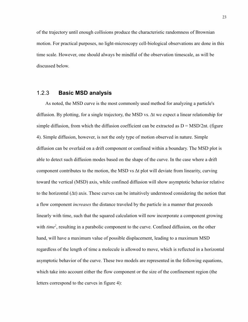
1.2.3 Basic MSD analysis
As noted, the MSD curve is the most commonly used method for analyzing a particle's
diffusion. By plotting, for a single trajectory, the MSD vs. Δt we expect a linear relationship for
simple diffusion, from which the diffusion coefficient can be extracted as D = MSD/2nt. (figure
4). Simple diffusion, however, is not the only type of motion observed in nature. Simple
diffusion can be overlaid on a drift component or confined within a boundary. The MSD plot is
able to detect such diffusion modes based on the shape of the curve. In the case where a drift
component contributes to the motion, the MSD vs Δt plot will deviate from linearity, curving
toward the vertical (MSD) axis, while confined diffusion will show asymptotic behavior relative
to the horizontal (Δt) axis. These curves can be intuitively understood considering the notion that
a flow component increases the distance traveled by the particle in a manner that proceeds
linearly with time, such that the squared calculation will now incorporate a component growing
with time2, resulting in a parabolic component to the curve. Confined diffusion, on the other
hand, will have a maximum value of possible displacement, leading to a maximum MSD
regardless of the length of time a molecule is allowed to move, which is reflected in a horizontal
asymptotic behavior of the curve. These two models are represented in the following equations,
which take into account either the flow component or the size of the confinement region (the
letters correspond to the curves in figure 4):

24
A) pure Brownian motion in 2 dimensios: MSD = 4DΔt
B) Confined Brownian motion:
(where Lx – length of the corral along the x-axis, σx – 2Dx, the diffusion coefficient along the x-axis. Similar derivation is used to the y-axis.)
C) Brownian with a flow/directed component: MSD = 4DΔt + ν2(Δt)2
(where ν – the flow speed).
A common way to analyze the mode of diffusion of a molecule is to track its trajectory,
generate the MSD vs Δt curve and fit the data to the three models, finding the best-fitting model
and the corresponding movement parameters.
While the MSD analysis is simple, accurate and widely used, it depends on the basic
assumption of simple diffusion, which should yield a linear relationship of the MSD with time.
The two cases described above are for simple diffusion overlaid with a second simple process.
Figure 4: Theoretical MSD plots.
25
However, not all trajectories show a linear relationship with time. Such diffusion processes are
defined as anomalous diffusion, with the MSD growing with tγ2. For the case where γ2>1 the
process is called superdiffusive (suggestive of directed motion) while for γ2<1 the process is
called subdiffusive (suggestive of obstacles slowing down the particle). For the normal Brownian
case γ2=1. A more general relationship of a molecule's displacement with time is formulated as
follows: ⟨r⟩ ~ tγν (r is the displacement at time t, the exponent ν = 1..n) where the MSD is the
particular case of ν=2, ( ⟨r2⟩ ~ tγ2). A study of the displacement moments higher than the 2nd
reveals information about the displacements at the tails of the distribution of steps76. The plot of
γν vs. ν is called the Moment Scaling Spectrum (MSS) and its slope (S) reveals information
regarding the particle's diffusion characteristics: S ≈ 0.5 when the motion is random, S < 0.5 for
confined motion and S > 0.5 for directed movement. Some groups employ the MSS analysis76,77
instead of the MSD one in order to classify the type of diffusion motion.
1.2.4 Diffusion in membranes
Since diffusion rates are affected by the surrounding medium, diffusion in biological
membranes differs greatly from that in aqueous solutions. The cell also contains many
components that can potentially interfere with protein diffusion, such as bulky extracellular
glycolipids or intracellular components such as the cytoskeleton. Furthermore, cellular responses
to extracellular stimuli can potentially affect the diffusion of proteins in the plasma membrane.
The following sections summarize some of the knowledge regarding diffusion in membranes.

26
1.2.4.1 Model membrane experiments
Early experiments investigating the diffusion of labeled lipids in model membranes using
FRAP (Fluorescence Recovery After Photobleaching) showed simple diffusion, with diffusion
coefficients in the range of 10-100 x 10-9cm2/s (1-10μm2/s)78. Experiments with labeled proteins
on erythrocyte spherocytes, devoid of the cytoskeletal protein spectrin, reported diffusion
coefficients of similar scale, 2.5 x 10⁻⁹cm2/s (0.25-1μm2/s)79 and ones conducted on membrane
blebs reported D values in the same range, 3 x 10⁻⁹cm2/s (0.3μm2/s)80. These early experiments
showed that the diffusion coefficient of proteins was marginally lower than that of lipids, which
was explained by the increased size of the diffusing molecule. It is important to note that these
experiments were carried out under conditions that aim to eliminate the contribution of the
cytoskeleton.
1.2.4.2 Experiments using cellular membranes
Diffusion in intact living cell membranes proved to be more complex. Proteins diffuse more
slowly in live cells, by a factor of up to 600 times. Numerous early studies have shown the
diffusion coefficients of proteins in cellular membranes to be in the order of 0.05 – 4 x 10⁻⁹cm2/s
(0.005 – 0.4 µm2/s)81 . Furthermore, while the mobile fraction of proteins in model membranes
approached 100%, in cellular membranes it was often lower. Such experiments spurred much
research investigating the reasons for the reduced diffusion of proteins in membranes.
Early theoretical treatment of diffusion in membranes, known as the Saffman-Delbrük
equations, shows that the size of a diffusing protein has little effect on its diffusion coefficient82.
This model treats proteins as cylinders of radius r, with the diffusion coefficient proportional to

27
log(1/r), suggesting an increase of 100-fold in protein size leads only to 2-fold decrease of the
diffusion coefficient.
An experimental test of the Saffman-Delbrük equations using bacteriorhodopsin and diO-
C18 in artificial membranes showed not only the validity of the equations, but also a relationship
between the protein fraction in the membrane and the diffusion coefficient. A decrease in the
lipid/protein ratio was found to reduce the diffusion coefficient83. A number of theories
explaining this observation were published. One explanation, drawing from percolation theory,
modeled diffusion as taking place in a liquid phase, obstructed with immobile obstacles
(proteins). Reduction in the fraction of the mobile phase corresponds with a reduction in the
diffusion coefficient. A second model, known as the 'milling crowd' model, treats the membrane
as a lattice where diffusion is described as the exchange of positions between two lattice points84.
In addition to predicting the reduction in diffusion rate with increasing protein fraction, this
model adds the untested prediction that for a similar fraction of the membrane occupied by
obstacles, the diffusion coefficient will be smaller for a larger number of small obstacles,
compared to fewer larger ones. However, while the crowding experiments with
bacteriorhodopsin reported slower diffusion than that recorded in pure lipid bilayers, the
diffusion coefficients measured in those experiments were ~3.4µm2/s83, an order of magnitude
faster than in live cells, suggesting that membrane crowding alone can not explain the
discrepancy.
Since most membrane proteins project to the extracellular space, interactions either with
glycolipids or extracellular matrix components can reduce their diffusion. These concerns have
been addressed and were shown to have a small effect on the diffusion of gold-tagged lipids
measured by single-particle tracking85. However, while the diffusion of the gold-tagged probe
rose from 1.1 x 10⁻⁹ to 2.8 x 10⁻⁹ cm2/s (0.11 to 0.28µm2/s) when the effect of extracellular

28
impediments is removed, those of fluorescently labeled probes did not change, suggesting that
the bulky, 40 nm gold probe may confer the sensitivity to the extracellular molecular crowding.
Furthermore, the treatment did not increase the diffusion coefficient to levels seen with artificial
membranes, suggesting that the extracellular matrix is not a major contributor to the retardation
of diffusion in cellular membranes.
Experiments with erythrocyte spherocytes lacking spectrin showed ~50 fold increase of the
diffusion coefficient compared with normal erythrocytes (2.5x10⁻⁹ vs 4.5x10⁻¹¹ cm2/s or 0.25 vs
0.0045 µm2/s) 79. Diffusion in membrane blebs lacking the membrane-associated actin
cytoskeleton showed similar results, 3x10⁻⁹ vs < 10-10cm2/s (0.3 vs < 0.01 µm2/s)80. However,
conflicting reports exist regarding the importance of the cytoskeleton in affecting diffusion.
FRAP experiments measuring movement of virus-like particles on mouse fibroblasts found an
increase of the mobile fraction with increased diffusion coefficient after treatment with
latrunculin B, an actin destabilizing agent86. On the other hand, FRAP experiments originally
designed to investigate the effect of the cleavage furrow on diffusion found no effect of
latrunculin B on either the mobile fraction or the diffusion coefficient87. It is worth noting that
different proteins may be differentially anchored or associated with the cytoskeleton and can
therefore be differentially affected by cytoskeletal-disrupting or stabilizing agents. While those
differences are expected and the specifics of the system under study should be considered when
comparing results, the majority of publications do report an effect of the cytoskeleton on
diffusion. The next section discusses one of the modern theories explaining this effect.
1.2.4.3 Hop-diffusion
In order to investigate the mechanism by which diffusion in cellular membranes is reduced,
Fujiwara et al. utilized high temporal resolution single-molecule microscopy to study the

29
diffusion of DOPE in NRK cells41. While video-rate (30 frames-per-second, 33 ms frame time)
single-molecule microscopy showed the expected ~0.5µm2/s diffusion coefficient with
unrestricted Brownian motion, high temporal resolution measurements (40,000 frames-per-
second, 25μs frame time) revealed the compartmentalization of the membrane into ~230 nm-
sized domains in which the DOPE probe diffused freely, with a diffusion coefficient of 5.4
µm2/s, similar to the one measured in artificial bilayers (9.4 μm2/s). The reduced diffusion
coefficient in the video-rate experiment resulted from the rate at which the probe moves between
adjacent compartments, on average every 11 ms. The terms macroscopic and microscopic
diffusion coefficients were coined to distinguish the slow, long-range diffusion, from the fast,
short range one and the term hop-diffusion is used to describe the motion as a whole, a barrier-
restricted diffusive process. This behavior was observed not only for lipid probes, but also for
TfR88,89,α-macroglobulin88, E-cadherin90, Band 391 and the GCPR μ-opioid-receptor92.
According to the actin-membrane cytoskeleton picket fence model93, two components
contribute to the compartmentalization of the plasma membrane with regard to molecular
diffusion: the membrane-associated cytoskeleton compartmentalizes free transmembrane
proteins by sterically interfering with their cytoplasmic tails, while other transmembrane proteins
can bind to the membrane cytoskeleton and serve as rows of “pickets”, obstructing diffusion and
forming compartments felt by both leaflets of the membrane93. The compartment size and the
hop rate appear to be cell type-specific, ranging from 30 nm to 230 nm and 1 ms to 17 ms,
respectively41. This model is supported by a number of experimental results: the actin
destabilizing agents latrunculin B92,94 and Cytocalasin D95 show an increase in the compartment
size and hop rate, resulting in overall faster macroscopic diffusion. Jasplakinolide, an actin-
stabilizing agent, shows a decrease in the hop rate, leading to a decrease in the macroscopic
diffusion rate95,96. Diffusion in artificial membranes does not show any compartmentalizaion.

30
Further, while previous theories predicted, in contradiction to the experimental results at the
time, that molecular aggregation should have minimal effect on the diffusion coefficient82, hop-
diffusion predicts that such aggregation will decrease the hop rate and therefore the macroscopic
diffusion rate41,97. This model suggests that all diffusing molecules, lipids and protein alike, sense
the presence of membrane compartments. It further suggests different mechanisms by which
molecular diffusion can be regulated: modulation of association with the cytoskeleton90, as well
as immobilization via aggregation97 have been shown. In addition, orchestrated control of the
cytoskeleton aimed at controlling protein diffusion is conceivable and is an appealing model for
investigation.

31
1.3 Single-molecule spectroscopy
1.3.1 Advantages of the Single-Molecule approach
Scientific data gathering generally entails the collection and averaging of large ensembles of
individual experiments, which yields an understanding of the features of a population consisting
of representative individuals. The design determines the scope of an individual experiment and
dictates the resulting average of the population. Many cell-biological and biochemical
experiments are designed to study the behaviour of proteins in cells. In microscopy-based
biological experiments, visual investigation of proteins (or molecules) is utilized to answer the
questions at hand. The scope of the experiment is defined by the investigator and is commonly
either a collection of many cells (e.g. one coverslip as one data point) or the individual cells
(each cell being a data point). In experiments studying the mobility or interaction of molecules,
many modern techniques such as FRAP or FRET (Förster Resonance Energy Transfer), define a
single cell as a data point. While the scope of the question is at the molecular level, the answer is
studied at a cellular level, by experimentally measuring whole cells or large areas within a cell as
the individual data points. Note that in such experiments no data is recorded regarding the
behaviour of the individual molecules; instead molecular behavior is inferred from bulk
measurements. Such experiments, while valid and informative, can mask the behaviour of small
fractions of the molecules in question. For example, FRAP-based measurements can generally
detect the mobile fraction and its diffusion coefficient, but rarely discern slow and fast-moving
molecules and can not distinguish between molecules that change their motion during the
acquisition time. When the population of molecules in question is heterogeneous, as is inherently
the situation in living cells, such bulk measurements can fail to detect transient behaviors that
may be functionally important, especially if mediated by molecules constituting a small fraction

32
of the total population. In order to detect such heterogeneous behaviour, experiments must be
carried in a manner that considers the individual molecules as the primary data unit. Such data
can be analyzed for the existence of different sub-populations, pooled together and averaged in a
way that reveals, rather than hides, heterogeneities among the molecules in question.
Cell-biological processes are dynamic in nature: protein movement, association or
modification can be transient, short-lived and reversible. Classical biochemical approaches such
as gradient-based protein separation, Western blotting, etc. are static, not carried out in live cells
and only capable of capturing a snapshot of such processes. Not only are they static, but due to
the nature of the methods, weak interactions, modification of only small fraction of proteins or
transient recruitment of proteins are hard to detect, if at all possible. For these reasons many
modern cell biological questions are answered by combining classical biochemical techniques
and live-cell methods, commonly light microscopy.
In order to study proteins in their living environment and capture such nuances as transient
behaviours, cell-biological experiments take advantage of recent technological advances in
microscopy techniques. Of note are the developments made in sensitive cameras and
fluorescence tagging of proteins. With better fluorophores, faster and more sensitive cameras and
available computational power, the study of individually tagged proteins is now possible.
Recordings of protein movement with temporal resolution on the order of milliseconds are
becoming common, while detection of individual fluorophores combined with computational
analysis can reveal the location of proteins with nanometer accuracy using light, not electron
microscopy. By following the individual molecules such single particle tracking (SPT)
experiments pave the way for new, fuller understanding of cellular dynamics.

33
1.3.2 The Setup of SPT experiments
Implementation of SPT is generally broken into three stages: data acquisition, particle
detection and tracking. The data acquisition setup, which is largely technical, is explained in the
Methods section, while the latter two, which involve conceptual nuances, are explained below.
1.3.2.1 Detection
Fitting the point-spread function (PSF)
The term 'resolution' relates to the ability to observe details in an optical system, indicating
the minimum distance between two objects that allows them to be distinguished from each other.
For this section we will also consider the accuracy of measurement under the term resolution.
Also, only point emitters (objects significantly smaller than the microscope resolution limit ) are
considered, and are referred to as either molecules or features.
All optical systems have limited resolving power due to the wave nature of light. As light
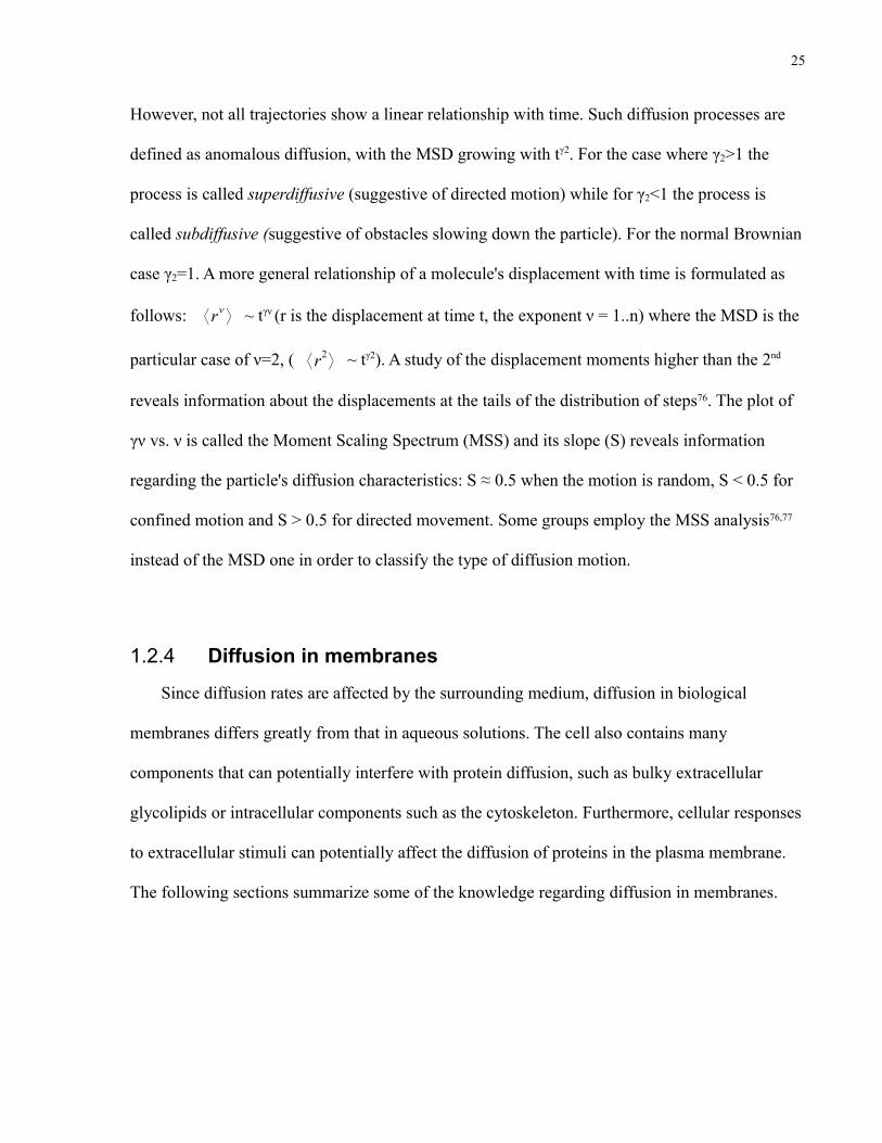
passes through an aperture, a diffraction pattern called the Airy pattern is formed in the observed
plane in a way determined by the point-spread function (PSF) of the optical system, with its
central spot called the Airy disc. The distribution of the light intensity in the Airy disc is
approximated by a Gaussian distribution. The resolution limit R refers to the case where the two
Airy discs from two point emitters overlap and merge into a single spot, which takes place when
the center of one Airy disc is at the minimum of the first trough of a second Disc (figure 5). For
perfect optical systems this can be calculated by Rayleigh's criterion :
R = 1.22 x λ/2NA (where λ: light wavelength, NA: numerical aperture of the lens)
34
As is evident from the equation, in order to increase the resolution one can either increase
the NA of the lens or use a smaller wavelength. As an example, for the setup most often used for
this thesis, the Rayleigh criterion is 0.61*655nm/1.45 = 275.55 nm. Note that while the Rayleigh
criterion is critical in resolving two objects, for the sake of simply detecting an object a different
set of criteria exists (discussed below). Also, it must be borne in mind that magnification has no
effect on the resolution limit.
The most common detection system used in light-microscopy setups is a two-dimensional
array of charge-coupled devices (CCD) onto which the image is projected and digitized. Such a
process segregates the distribution of light into the individual pixels of the CCD. This allocation
of light into discrete units generates a finite number of pixels representing each point emitter.
Different methods have been developed to determine the location of the emitter, but the most
robust one utilizes the knowledge of the properties of the PSF in order to find its center (figure
6).
Figure 5: Airy discs and resolution. (A) the light distribution of a point emitter. (B) two point emitters are resolved. (C) two point emitters are closer than the Rayleigh criterion, their Airy discs merge and they can not be resolved.

35
Figure 6: Schematic of single-molecule detection.Individual point emitters are spread and recorded over a number of pixels due to light diffraction. The discrete data points are fitted with a 2D Gaussian function and the center and amplitude of the Gaussians are used to define the location and intensity of the point emitter. dX and dY are the uncertainty in the fitting, reported as the standard deviation of the Gaussian fitting. The better the signal-to-noise ratio the 'sharper' the Gaussian distribution and the localization of the point emitter.

36
Since the spatial distribution of the light intensity in the Airy disc is Gaussian, the
distribution of recorded intensities in the pixels should be Gaussian as well. Therefore, by fitting
a Gaussian function to the recorded intensities, the underlying light distribution can be
calculated, along with its center, which defines the true location of the emitter. The pixel size is
finite and represents a specific area of the specimen, effectively limiting the localization
accuracy to be at least one pixel. However, by finding the underlying light distribution and its
center it is possible to achieve localization of the emitter in a continuous space, resulting in sub-
pixel localization. The emitter is not only located to a specific pixel, but to specific coordinates
within that pixel. However, the subdivision of the PSF onto pixels adds another technical layer to
the process. The different components in the system interact to produce the discrete data points
of the PSF. The acquisition of these data points must be optimized in order to maximize the
accuracy with which a Gaussian can be fitted to the recorded data. The following components are
critically important:
• Pixel size: The physical size of the pixels has a direct effect on the Gaussian fitting. The
smaller the pixel size the more pixels are covered by the Airy disc and more data points
are available for the fitting, resulting in better fitting. However, smaller pixels generally
have lower sensitivity, introducing more noise to the recorded data. Pixel size is not
easily changed and tends to be constant for the duration of a project, unless the
microscope camera is changed.
• Magnification: Similar to the effect of pixel size, the magnification factor determines
over how many pixels the PSF will be distributed; the higher the magnification the more
pixels will be covered by the light from a point emitter. However, with increased
magnification fewer photons will reach each pixel, again leading to reduced signal and a
proportionately increased contribution of the noise. Unlike the pixel size, magnification is

37
easily changed by changing objective lenses and/or by introducing intermediate lenses in
the light path.
Both pixel size and magnification touch upon the balance between obtaining more data
points for fitting (small pixel size or large magnification) and the quality of the recorded data
(fewer photons reaching each pixel). The signal-to-noise ratio (SNR) is indeed the most
important factor determining the quality of the Gaussian fitting. Theoretical treatment of the
issue shows a direct relation between the SNR and the quality of the fit98, with smaller errors for
both the amplitude and location of the Gaussian as SNR improves. Translated into imaging
terms, it reflects the balance between high magnification, small pixel size, rate of acquisition, the
properties of the fluorophore and of the light source, and the various sources of noise. With the
exception of two labeling methods (colloidal gold phase-contrast imaging and quantum dots
fluorescence imaging) most fluorophores are of relatively low quantum yield and push the
technology to its maximum capacity in order to observe individual molecules. Under such
conditions the contribution of noise is significant, and the acquisition setup needs to be carefully
calibrated in order to achieve confidence in the results.
Determination of the spatio-temporal resolution.
Signal strength is a function of the type of fluorophore used, the excitation light, the system
optics and the acquisition setup. Assuming a choice of good fluorophores, bright excitation light
and well-matched optics, longer acquisition time will increase the signal significantly more than
it will the noise. Since the dark and electronic noise are poorly correlated with the signal, and
since the better the optical system the lower the contribution of stray light, once the excitation
light is maximally used the best method to increase the signal over noise is to use long

38
acquisitions, leading to better SNR and more accurate determination of the location of the
emitter.
When following moving objects with a camera, the observed location is recorded during a
time window (acquisition time or frame time) and represents an average location during that
time. Using long frame times to track fast-moving particles can pose a severe problem, as the
object may appear elongated. Furthermore, phenomena that take place for short periods of time,
such as the short association of two molecules, can be missed if the acquisition time is longer
than the association time. Therefore, short acquisition times are desired to observe fast moving
objects as well as transient behaviours.
Short acquisition times, however, reduce the quality of the signal and hinder the correct
estimation of a molecule's position. The balance is dictated by the system specifications, with a
tendency to push for the fastest acquisition possible with a specific set of fluorophores and
equipment. In summary, it is important to consider the acquisition time and to bear in mind that
only phenomena occurring on a similar or longer time scale can be observed.

39
1.3.2.2 Tracking
Once positions for the different molecules are determined, tracks can be built. A track is the
recording of the advancement in time of the location of a single feature.
Linking
The main problem confronted by an algorithm intended for tracking features over time lies
in determining which feature in frame x connects to which feature in frame x+1. Depending on
the displacement and density of features, such assignment can be as simple as assigning the
spatially closest feature in frame x+1, but the situation is rarely this simple.
In order to connect the features, the algorithm must use specific criteria to determine how
likely two features are to be connected, such as the distance between them, the speed and
direction of movement (if there is one), etc. Each parameter is assigned a “cost”, with the more
likely links having lower costs. All possible connections are placed in a cost matrix and the
combination giving the lowest cost is chosen.
Such an approach, called Global Nearest Neighbor, can be extended over multiple frames.
This allows for the most likely linking along many frames to emerge. The specific costs used are
described in the Methods section.

40
Gap closing, Merge/Split events
While linking one frame to the next is the basis of tracking, a feature might be lost for any
number of reasons, including moving out of focus, blinking, failure of detection for a few
frames, merging with another feature etc. Such track ends are not due to fluorophore bleaching,
but rather a temporary condition. In such cases it is best to bridge the gap and link the different
sections in order to provide a longer track. The two cases (gaps due to disappearance and
merging/splitting events) are different in nature and interpretation, but are treated mathematically
in the same way. A second cost matrix is formed in which the different parameters represent the
costs associated with a track ending vs merging or having a gap, and another Global Nearest
Neighbor analysis is used to find the most likely gap-breaching possibilities. The result is a
matrix representing the locations of the tracked features in each frame, with its merging/splitting
events noted.
Considerations for tracking
There are many obstacles to successful and reliable tracking of features. Appropriate data
must be acquired in order to utilize the described model.
A general, yet inappropriate tendency is to label as many molecules as possible in order to
achieve a large sample size. While this is useful in some cases, for SPT purposes over-labeling is
among the most detrimental issues. The first reason is increased background. The more features
that are present in the observation area the higher the background due to stray light. This reduces
the quality of detection and results in low positional accuracy or even lack of detection, leading
to more gaps and less reliable linkage of features. The other problem often caused by over-
labeling is loss of accuracy of the linking and gap-closing procedures. While robust, the
algorithms used for these determinations are still based on geometrical relationships, and an

41
abundance of features not only makes the calculation longer, but also introduces many potential
erroneous links. Sufficient density is required, however, not only to achieve large sample size but
also to observe molecular interactions, which inherently require features to be close. Careful
calibration of the labeling density is therefore required for each application.
A second obstacle is the requirement for features to remain in the focal plane. As features
move out of the focal plane their PSF is distorted and they can no longer be detected based on its
shape. This problem is avoided by using TIRF microscopy. While a good solution, TIRF is not
ideal in every case. For example, studying receptor diffusion at the basal side of the cell may
produce atypical behavior, since movement may be hindered due to the abundance of focal
adhesions. Further, if any intervention is required, the dorsal membrane is more readily
accessible than the ventral one. Another option is to use cell types with flat surfaces, or to induce
such surfaces. Primary macrophages are particularly suitable for this purpose, as over their
maturation period they spread and flatten on the coverslip, exhibiting extensive radial
lamellipodia. However, even in flat cells the plasma membrane exhibits many ridges, and
features do indeed move in and out of focus, causing at best gaps in tracks and, in the worst
cases, fragmentation or loss of tracks.
While most fluorophores seem to emit constant fluorescence, the process is stochastic. Some
fluorophores, notably Quantum dots but also fluorescent proteins, have a tendency to blink and
enter dark states for extended periods of time (up to seconds). Such blinking is a major hindrance
to tracking, as a feature is lost for a significant number of frames. Under such circumstances a
lower density of labeling is required in order to achieve more accurate linking. Still, the end
result tends to be the existence of a larger number of shorter tracks due to the long gaps.

42
1.3.2.3 Data treatment
The basic data units obtained in SPT experiments are matrices of features positions in the
different frames and tracks linking these features over frames. While the post-acquisition
analysis necessary is significant, it also allows for great flexibility. Data can be investigated on a
per-track basis. Such analysis, however, is inefficient. Since all the data points in the population
of tracks are available, SPT experiments are best analyzed by a clustering approach, usually
reporting histograms as well as means, and searching for different sub-populations that exhibit
similar behaviour. For example, one can focus on mobile features and cluster them by speed,
intensity, etc. and find the fraction that is fast or exhibits specific fluorescent intensity. Further,
outliers can be detected and either discarded or investigated separately. Such clustering allows
the delicate detection of transient and uncommon behaviours, the great advantage of SPT over
traditional detection techniques.

43
2 Methods2.1 Cells
Primary human macrophages were acquired as following: blood was collected from a
healthy donor, diluted 4-fold in PBS and gently layered on 14 mL of Ficoll-Paque in 50 mL
tubes. Tubes were spun at 1800 rpm for 30 minutes at room temperature. Erythrocytes and
platelets are sedimented, monocytes and leukocytes form a white layer on top of the Ficoll and
clear plasma remains as the top layer. The white layer was collected using a transfer pipette and
washed three times in ice-cold PBS. Cells were plated in culture medium (RPMI containing 10%
FBS, 1 ng/mL MCSF, 0.0625 mg/mL penicillin, 10 μg/mL streptomycin and 0.25 μg/mL
amphotericin B) at a density of 5-10 million cells/mL on 12 mm coverslips and allowed to
adhere for 1-2 hrs, after which they were washed gently in warm culture medium. Monocytes
remain adhered to the coverslip while lymphocytes are washed away. Half the medium was
changed every other day. Cells were used at day 7-10 when exhibiting a flattened and extended
morphology.
2.2 AntibodiesAnti-FcγR-IIa IV.3 antibody was purchased from the Sunnybrook hospital hybridoma
facility. IV.3 is FcγR-IIa specific and is a 'blocking' antibody (blocks binding of the ligand to the
receptor).
Full length IV.3 was papain-digested overnight using latex bead-coupled papain. The digest
was filter-separated from the immobilized papain and Fab fragments were separated from un-
digested IV.3 using FPLC. One mL fractions were collected and analyzed by Western blot to
detect the Fab fragment-containing fractions.

44
2.3 LabelingAll incubations were done in cold HPMI on ice, unless otherwise stated. All PBS used for
incubations was supplemented with 1 mM Ca+2, 1 mM Mg+2 and 2g/L glucose.
Labeling of FcγR-IIa for tracking with Cy3 or DyLight549 was done as follows: cells were
washed with cold HPMI prior to a 10 minute incubation with IV.3 Fab fragments. Use of Fab
fragments is necessary in order to eliminate antibody-dependent cross-linking of the receptors or
engagement of the receptor via the antibody Fc portion. Cells were gently washed in cold HPMI
and incubated 10 minutes with secondary goat anti mouse IgG Cy3-conjugated Fab fragments.
After another wash in cold HPMI cells were in some experiments incubated for 10 minutes with
a tertiary donkey anti goat IgG Cy3-conjugated Fab fragments in order to increase the signal
intensity. A final wash step was done in warm PBS.
For quantum dot (QD) labeling, cells were washed with cold HPMI prior to a 10 minute
incubation with IV.3 Fab fragments, a second wash with HPMI and a 10 minute incubation with
secondary biotin-conjugated Fab fragments. The third wash and 10 minute cold incubation with
strepavidin-conjugated QDs were done in cold PBS, since cell culture media contain biotin,
which would block the binding sites on the streptavidin-conjugated QDs. A fourth wash and a 1
minute incubation with HPMI containing biotin were used in order to block empty streptavidin
binding sites, and a final wash step was done in warm HPMI followed by warm PBS.
2.4 Drug treatmentsWhere indicated, latrunculin B was added to the labeling medium 10 minutes prior to
imaging and was maintained throughout the imaging time. Final concentration was 10 μM and
imaging time was up to 15 minutes in the presence of latrunculin B.

45
2.5 Single molecule system specifics
2.5.1 Acquisition setup
Tracking experiments were carried with a Zeiss Axiovert 200M microscope equipped with a
100x, 1.45 NA lens. A second lens was installed between the microscope and the camera with a
2.4 magnification factor. The physical resolution limit, based on the Rayleigh criterion (1.22xλ /
2xNA) is 240 nm for a Cy3 or DyLight549 fluorophore (emission at 570 nm) and 275 nm for a
QD655 (emission at 655 nm). The light source used was a mercury lamp (X-cite 120 by Exfo).
Images were digitally recorded using a Hamamatsu ImageEM camera with a 16 μm x 16 μm
physical pixel size, driven by a computer equipped with the image acquisition software Volocity
(Improvision Inc).
2.5.2 Detection
Input for the detection steps is comprised of the image series to be analyzed and the
detection parameters, summarized in table 2. The detection code, developed at the laboratory of
Dr. Danuser, The Scripps Research Institute, Department of Cell Biology, performs the following
steps:
1. Optional integration of sequential images in order to increase the SNR of dim features as
well as reduce noise contribution. This feature is generally used for low-intensity
fluorophores (Cy3 and DyLight) only. Care should be taken when using this feature, as
fast diffusing molecules will average out with background rather than increase their
relative signal. Generally, if during the acquisition time a molecule diffuses significantly
more than the PSF projection onto the CCD, this feature should not be used.
2. Generic Gaussian filtering of the integrated images.

46
3. Background estimation based on the total image space after discarding outliers. The
background is calculated as a spatial moving average in order to account for illumination
heterogeneity and is treated as a Gaussian distribution rather than a fixed cut-off value.
4. Localizing local maximum: Local maxima are pixels that are significantly brighter than
their local background. For each integrated image the software finds the pixel locations
with brightest values (pixels whose neighbours are all of lower intensity) and calculates a
p-value to establish whether they are significantly above the local background
distribution.
5. Optional PSF sigma evaluation. Since the PSF projection onto the CCD rarely, if ever,
produces the theoretical light distribution, an effective PSF projection is calculated based
on the light distribution around pixels designated as a local maximum. The PSF
projection is termed the PSF sigma, or the standard deviation of the Gaussian fitted to the
light distribution. The initial estimation is calculated based on the experimental optical
setting.
6. PSF fitting with optional Mixture Module Fitting (MMF): Pixels designated as local
maxima serve as the initial location for PSF fitting in order to 1) validate that they
conform to a point-emitter and are not noise and 2) find their sub-pixel localization. If
MMF is activated, the software tries to fit a second PSF within the same local maximum.
If the fitting is significantly better, then it is accepted and a third one is tested, etc. This
module allows the separation of two features which are closer than the theoretical
microscope resolution based on the light distribution on the the CCD..

47
Table 2: Detection parameters
Parameter Meaning Value range commentsPSF sigma The standard deviation
of the Gaussian approximation of the central Airy disc arising from the PSF projection onto the CCD.
Typically from ~0.5 (for a GFP molecule, 1.45 NA, 100x and 16 μm physical pixel size) to ~1.5 (Qdot655, 1.45 NA, 240x, 16 μm physical pixel size)
The PSF sigma is calculated based on the emission wavelength, the lens NA, the total magnification in the system and the pixel size of the CCD
MMF A switch to activate the MMF functionality
Yes/No
Bit Depth The acquisition bit depth, used to normalize the intensity values
8,12,16
Alpha Local maximum
The required alpha-value for detecting the initial local maximum above background.
~0.0001 (for QDs) to 0.1 (Cy3/DyLight)
This is one of the most critical parameters. A high setting will result in lack of detection of dim features, while a low one will result in more false-positives. It is calibrated for every acquisition setup independently.
Fitting alpha values Three alpha values for different statistical tests used to validate the fitting of a PSF around a local maximum. 1) Residuals testing when comparing two fitted kernels with MMF. 2) Amplitude testing (this is different than the Alpha Local Max parameter. This parameter refers to the fitted data compared to the background).3) Distance testing when more than one
Typical values are 0.05 for all tests.

48
PSF is fitted. The distance between two features needs to be significantly larger than the uncertainty in the positional fitting.
Number of sigma iteration
The number of iterations when trying to evaluate the PSF from the local maximum (step 5)
3-10
Integration window The number of frames to integrate (step 1)
0 for QDs1-2 for mobile Cy31-5 for immobile Cy3
This is typically used for low intensity fluorophores.
The output of the detection step is a structure holding for each analyzed frame three lists
representing the X position, Y position and amplitude of each fitted PSF as well as the standard
deviation in the fitting of each value.
2.5.3 Tracking specifics
Input to the tracking step is comprised of the output of the detection step (the detected
features in each frame) and the tracking parameters, summarized in table 3. These are the
tracking steps:
1. Initial linking. A nearest-neighbor approach is used to connect features from frame to
frame, with cost parameters penalizing unlikely linkages and user-assigned hard limits for
those cost parameters (see table 3). The linking is overlaid with an optional Kalman filter
approach (self-adaptive model), which calculates and adapts the costs on-the-fly from
previous linking steps. This process is repeated a second time from end-to-start and a
third from start-to-end, each time refining the Kalman parameters. The result is a linkage
matrix from frame to frame.

49
2. Gap closing/merge-split: The second step connects the linked segments over periods at
which a feature is lost and optionally connects merging/splitting events. This is again
established by a nearest-neighbor approach with user-defined hard limits costs (table 3)
overlaid with a Kalman filter.
Table 3: Linking parameters
Parameter Meaning Value range commentsLinear motion Whether or not to use
a linear-motion filter.yes/no If linear motion is used
and a track is assigned to be linear, its cost-matrix is skewed such that future linking along its axis is more likely. Since FcγRIIa tracks did not exhibit a significant linear population it was set to 'no'.
Min/max search radii User-defined hard minimum and maximum distances for linking two features. Features that are further or closer apart then those distances cannot be linked in a single trajectory.
2-10 pixels, depending on frame time and speed of particle
The actual search radius is calculated on-the-fly, based on the tracks' previous trajectory, but the user can impose min/max values such that extremely long radii will not contaminate linking, or lower-than-one values will not be used.
Min/max amplitude ratio
The minimum and maximum intensity ratio of features before/after merge and split
0.25/4 for Cy3 and DyLight.0/inf for QDs (due to blinking and their extreme brightness, intensity information is irrelevant in QD analysis)
When features merge/split the amplitude of the individual features compared to the merged one should reflect the event. This parameter allows the user to set limits on the intensity ratios.

50
Minimum segment length
The minimum continuously-linked segment length to consider carrying on to the gap-closing step
3-5. Generally, 2-frames-only linkages can arise due to noise and a minimum of 3-frames-linkage is required. Longer minimum linkages can result in better (less-fragmented) tracks but may result in loss of data. Low SNR and detection quality may result in short-linkages.
Max angle The maximum angle between two linear continuously-linked segments that allows gap-closing between the two
30-45 If two segments were classified as linear and are considered for gap-closing they should travel in similar direction. Not relevant for FcγIIa tracks.
Time window The time between a segment end and another segment start that allows linking them.
6-20, depending on frame time.
This parameter describes the amount of time a feature is allowed to disappear and still gap-close it into the same track. While higher values lead to better chance of closing gaps, the search radius increases with time and may lead to erroneous linkages.
The output of the tracking step is a list of tracks, each showing the X and Y positions and
amplitude of a feature in each frame (as well as the standard deviation for the values). Where
gaps are closed the information is missing for the intermittent frames. If merge/split events were
assigned for a track it becomes a “compound track”, reporting the frames at which merge/split
events took place and breaking the X/Y/Amp data into segments, each corresponding to the
independent features before/after the merge or split and the time they spend merged.

51
2.5.4 Diffusion analysis
Diffusion analysis takes the trajectories and fits the distribution of steps to the models
discussed above (sections 1.2.2 and 1.2.3 ). Tracks are first checked for asymmetry. If classified
as such, they are analyzed as a 1D problem. The method used for diffusion analysis is the
Moment Scaling Spectrum analysis76,77(section 1.2.3). Tracks are classified as either free
Brownian (random walks), confined Brownian (random walk within a corral) or directed motion
(ballistic component overlayed on a random walk) based on their MSS slope. The default
assumption is Brownian diffusion unless the slope is outside a defined range of error. For each,
the diffusion coefficient is given based both on the second moment of the MSS analysis as well
as the traditional MSD analysis; the latter was used for all coefficients used in this thesis, similar
to work published by other groups utilizing both MSS and MSD approaches77. For confined
Brownian tracks, a confinement region is reported based on the distribution of positions (not
based on fitting of the MSD curve to the confined diffusion model). Directed tracks also report
the rectangular boundaries of the track and its direction.

52
3 Results
3.1 Calibration slides
3.1.1 Detection of single molecules, determination of minimal quanta.
Generally, the first step when employing a single-molecule approach is validation that the
acquisition system indeed detects single molecules. The most widely employed method is the
detection of single-step photobleaching of the detected particles. Since photobleaching is an
irreversible phenomenon, and since the fluorescence of a single molecule is approximately
constant under constant acquisition conditions, a single-molecule's photobleaching event should
cause a disappearance of the feature rather than gradual decay of signal. Moreover, if two or
more fluorophores are conjugated to a single molecule (i.e. an antibody coupled to a number of
fluorophores), precise, quantized photobleaching steps are expected.
Figure 7 shows a coverslip coated with a low concentration of DyLight549-conjugated Fab
fragment (a monodisperse coverslip; Cy3 and DyLight549 were both successfully employed and
used interchangeably). The software identifies local maxima and tries to fit a Gaussian
distribution of light in their vicinity. Blue-colored pixels reflect the location of local maxima,
red-colored ones are pixels within which the Gaussian center is located and pink-colored ones
represent pixels where the fitted Gaussian center resides in the same pixel as the original local
maximum.
Following the intensity of the features over time shows single-photobleaching steps. Two
examples are given in figures 8 and 9, of long- and short-lived fluorophores, respectively. For
illustration reasons, those two cases show two-step photobleaching, but the majority of features

53
show a single-step disappearance. Three-step photobleaching is rarely seen, suggesting that the
majority of features are indeed single-fluorophore with a minor population of two-fluorophores.
A second approach for finding the intensity of features is to use an intensity histogram.
Populations with similar intensity can be detected by fitting multiple Gaussians to the histogram.
This approach is shown in figure 10. The fitting results suggest a major population of features
with mean intensity of ~0.02 units and a minor one with double that intensity. The cumulative
distribution function is presented for comparing the fitting to the data.
Intensity analysis is crucial for aggregation studies, as the underlying assumption is that
clustered receptors will show an increase in features intensity proportional to their aggregation
state. For such analysis to be accurate not only the ability to distinguish the different populations
is needed but also the confidence that a single molecule is labeled with a single fluorophore. In
the case of DyLight (and Cy3), 75% of molecules are indeed labeled with a single fluorophore.
Similar monodisperse analysis was carried for Quantum Dots (QDs), shown in figure 11.
Figure 12 shows the intensity of a single QD over time. As can be seen, the intensity of QDs
fluctuates with periods of complete disappearance (blinking). In figure 12 frames 6, 70-84, 88-89
and 93-100 show blinking. The blinking characteristics of the QDs renders intensity-based
studies impossible but due to their increased brightness and lack of bleaching they are a good
complement to traditional chemical fluorophores such as Cy3.
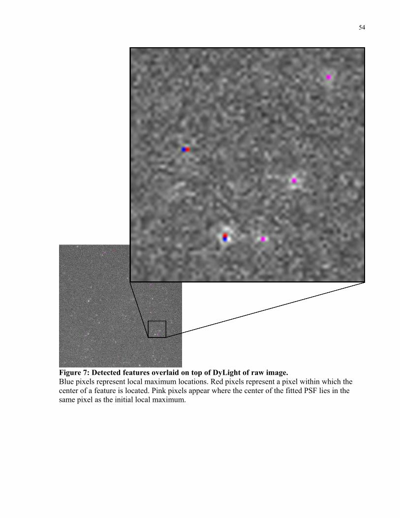
54
Figure 7: Detected features overlaid on top of DyLight of raw image. Blue pixels represent local maximum locations. Red pixels represent a pixel within which the center of a feature is located. Pink pixels appear where the center of the fitted PSF lies in the same pixel as the initial local maximum.

55
Figure 8: Intensity of single DyLight molecule over time, long track. The intensity is stable at ~0.045 level before dropping to ~0.025. This feature lasted until the end of the acquisition period, 215 frames (1:45 minutes).

56
Figure 9: Intensity of single DyLight molecule over time, short track. The intensity is stable at ~0.035 level before dropping to ~0.02 and finally disappearing (photobleaching). This feature lasted 14 frames (7 seconds).
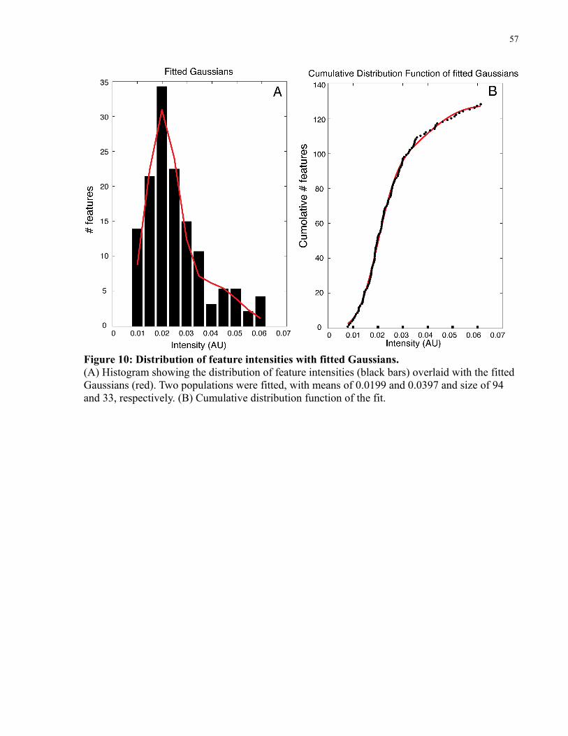
57
Figure 10: Distribution of feature intensities with fitted Gaussians. (A) Histogram showing the distribution of feature intensities (black bars) overlaid with the fitted Gaussians (red). Two populations were fitted, with means of 0.0199 and 0.0397 and size of 94 and 33, respectively. (B) Cumulative distribution function of the fit.

58
Figure 11: Detected features overlaid on top of QDs raw image. Blue pixels represent local maximum locations. Red pixels represent a pixel within which the center of a feature is located. Pink pixels appear where the center of the fitted PSF lies at the same pixel as the initial local maximum.

59
Figure 12: Intensity of a single QD over time. The intensity is not stable and fluctuates greatly. The QD blinked during frames 70-84, 88-89 and 93-100.

60
3.1.2 Positional accuracy
The positional accuracy of detected features is defined as the standard deviation of the X and
Y fitting of the Gaussian center. The accuracy is critical for the sub-diffraction resolution and
sub-pixel localization of the software. Section 3.3 discusses a case where the positional accuracy
has direct implications on data interpretation.
As mentioned above, the SNR is the strongest determinant of the fitting98. Figures 13 and 14
show the distribution of positional accuracy of the x-axis in the fitting of DyLight and QDs (the
y-axis values are similar to the x-axis ones). While DyLight gives a mean accuracy of ~63 nm
QDs are superior, with a mean of ~13 nm. Reports in the literature go up to a few nm accuracy99
for fixed samples, but are generally larger for live-cell, fast-acquisition microscopy.
The relationship of intensity to positional accuracy is demonstrated in figure 15, where
DyLight features of different intensities exhibit increased accuracy with increased intensity.
Of note is the relationship between positional accuracy and the MMF functionality (fitting
more than one PSF near a local maximum in order to resolve features closer together than the
resolution limit). Since positional accuracy benefits from high SNR, the use of total higher
magnification leads to worse accuracy by spreading the light over many pixels. For that reason,
use of a 100x lens alone gives better accuracy than the addition of a second, 2.4x lens between
the microscope and camera. MMF, however, benefits from having as large a PSF spread as
possible in order to maximize the number of data points for fitting and therefore the ability to
detect two distributions. In fact, MMF is only barely possible with 100x magnification, since the
PSF spread is only marginally larger than one pixel.

61
Figure 13: Positional accuracy distribution, immobilized DyLight.The mean positional accuracy is 63±21 nm.
Figure 14: Positional accuracy distribution, immobilized QD. The mean positional accuracy is 13±2 nm.

62
Figure 15: Effect of feature intensity on its positional accuracy. The positional accuracy of features is plotted against their intensity. Higher intensity leads to better positional accuracy.
0.01 0.02 0.03 0.04 0.05 0.06 0.07 0.08 0.09 0.10
20
40
60
80
100
120
140
Amplitude (au)
Posi
tiona
l acc
urac
y, x
-axis
(nm
)

63
3.2 Fcγ-receptor IIa is monomericIn order to find whether FcγRIIa exists as a monomer or a higher-level complex we used a
saturation and photobleaching approach. Cells were fixed and labeled with increasing
concentrations of primary Fab, followed by a constant but saturating level of secondary Cy3-
labeled Fab. As the concentration of the primary antibody increases, more features are detected.
If FcγRIIa exists as a dimeric, trimeric or other-order complexes, such complexes should be a
few nm apart and therefore detected as single features with higher intensity (note that for this
application the MMF functionality is not used, as it may detect the individual features). A
dimeric complex exhibits double the intensity of a single receptor, a trimeric complex three times
etc. Since the intensity of single fluorophores is assumed to be normally distributed, the resulting
distribution of intensities represents a multiple-Gaussian distribution and can be fitted to such
distribution, finding the underlying populations of single-receptors, dimers, trimers, etc.100(figure
16).
Following those populations over time leads to a population-photobleaching experiment, in
which the mean intensity of each population is expected to be constant while the number of
features is reduced over time as fluorophores bleach. For example, as dimers bleach, fewer
dimers should be detected but their mean intensity should remain constant. Furthermore, if the
previous experiment failed to detect the smallest (monomeric) population due to an abundance of
dimers and mistakenly interpreted the dimeric one to be monomeric (as a result of exhibiting the
lowest mean intensity), a photobleaching experiment would reveal this error by converting the
dimers to monomers.
For such experiments, a monodisperse coverslip is analyzed with identical acquisition and
analysis parameters in order to identify the minimum quantum. While the values of a single
monodisperse Cy3 intensity may differ from the cell-attached one, due to differences in the

64
environment and focus, they should serve as a guideline to the expected intensity of a single
fluorophore.
Figure 16: Schematic of a saturation experiment. At low labeling conditions (A) a small fraction of the features are expected to be labeled and dimeric features may be labeled with only one Fab-Cy3. The histogram should fit one Gaussian (B). At high labeling conditions (C) most of the features are labeled and dimers are labeled with two Fab-Cy3 molecules. If the population is mostly monomeric, the histogram should fit a larger population with the same mean (D) and potentially a small one with double the mean intensity. If the population has a substantial fraction of dimers, a major population with double the intensity should be seen (E)
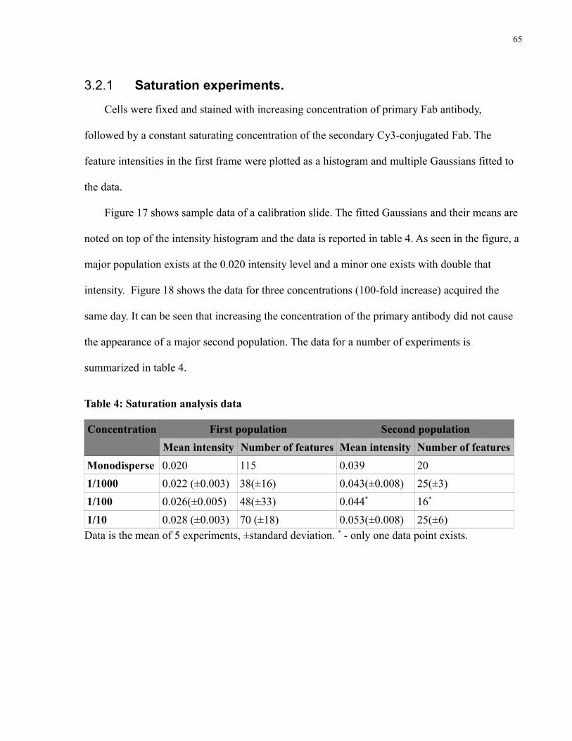
65
3.2.1 Saturation experiments.
Cells were fixed and stained with increasing concentration of primary Fab antibody,
followed by a constant saturating concentration of the secondary Cy3-conjugated Fab. The
feature intensities in the first frame were plotted as a histogram and multiple Gaussians fitted to
the data.
Figure 17 shows sample data of a calibration slide. The fitted Gaussians and their means are
noted on top of the intensity histogram and the data is reported in table 4. As seen in the figure, a
major population exists at the 0.020 intensity level and a minor one exists with double that
intensity. Figure 18 shows the data for three concentrations (100-fold increase) acquired the
same day. It can be seen that increasing the concentration of the primary antibody did not cause
the appearance of a major second population. The data for a number of experiments is
summarized in table 4.
Table 4: Saturation analysis data
Concentration First population Second populationMean intensity Number of features Mean intensity Number of features
Monodisperse 0.020 115 0.039 201/1000 0.022 (±0.003) 38(±16) 0.043(±0.008) 25(±3)1/100 0.026(±0.005) 48(±33) 0.044* 16*
1/10 0.028 (±0.003) 70 (±18) 0.053(±0.008) 25(±6)Data is the mean of 5 experiments, ±standard deviation. * - only one data point exists.

66
Figure 17: Sample data of a Cy3 calibration slide. Two areas of a calibration slide are shown. Black bar: intensity histogram; Red: fitted Gaussian. The data is summarized in table 4.

67
Figure 18: Sample data for a saturation experiment. Three increasing concentrations of the primary antibody are shown with the intensity histogram and fitted Gaussians. As can be seen, no major second population appears. The data is summarized in table 4.
68
3.2.2 Photobleaching experiments.
Cells were fixed and stained as for the saturation experiment and were followed for 30-90
seconds at a rate of one frame-per-second with constant illumination in order to photobleach the
sample. Gaussian populations were fitted to the intensity histogram of each frame and the mean
intensity and number of features were plotted as reported from the lowest Gaussian fit (figure
19).
It can be seen that while the number of features in each population decreases dramatically,
the mean intensity remains constant (within certain fluctuation) but does not drop significantly,
suggesting that the smallest population is a monomeric one. Similar results were observed for
multiple experiments.

69
Figure 19: Results of representative photobleaching experiment. Mean intensity (red) and number of features (green) for the first fitted population are shown for two representative cells. The mean (intensity) of the population fluctuates slightly but remains constant throughout the observation period while the number of features decreases as they photobleach.

70
3.3 Diffusion in basal stateIn order to characterize the movement of FcγRIIa in the basal state receptors were labeled as
described with either Cy3 or QDs and followed for periods of up to 30 seconds. QDs have the
potential to affect the receptor mobility via cross-linking due to their multivalency and
comparison of the basal condition is required in order to verify a behaviour similar to the Cy3-
labeled receptors. Figure 20 shows an example of a tracking experiment performed with QDs
overlaid on the raw image (first frame). A free Brownian track and a confined track are
highlighted. Figure 21 shows the same tracks color-coded based on their diffusion mode. As
evident, the basal state is divided between the free and confined modes with little directed
motion. The breakdown of diffusion mode is shown in figure 22 for five different Cy3
experiments and in figure 23 for three different QD experiments. The average percent of
confined, free and directed tracks for the Cy3 data is 71%, 25% and 3%, while for the QD data it
is 53%, 43% and 4% (summarized in table 5). Such discrepancies can arise due to over-
representation of mobile tracks by the QDs. As QDs do not bleach their acquisition times are
longer than those for Cy3, allowing them to move in-and-out of focus for prolonged periods
during the acquisition time, resulting in fragmented tracks which can sometimes, but not always,
be gapped. Since immobile/confined features do not tend to move out of focus (and therefore
show less fragmentation in tracking) this issue may lead to over-representation of free Brownian
tracks, compared with confined ones, in the QD data.
A second global bias, equally affecting Cy3 and QD tracks, exists toward the confined
tracks: as 20 data points are required in order to perform the MSS analysis accurately, tracks
shorter than 20 frames are discarded. Since freely moving features are generally harder to track
for long periods compared to immobile/confined ones, a disproportionate amount of free
Brownian tracks may be short and discarded when selecting tracks longer than 20 frames.
71
The diffusion coefficients (D) for the confined and free diffusion modes are shown in figures
24 and 25 for Cy3 and QD data (the directed diffusion mode has negligible contribution). The
mean D for Cy3 tracks is 0.02 μm2/s (confined) and 0.04 μm2/s (free), whereas for the QD data it
is 0.04 μm2/s (confined) and 0.08 μm2/s (free) (table 5). In both cases free Brownian tracks
exhibit D twice as large as confined ones. QDs are acquired with a temporal resolution three
times faster compared to Cy3, while exhibiting a higher SNR and should therefore be a closer
representation of the real D. The fact that faster, rather than slower diffusion is observed for QDs
suggests that no receptor cross-linking is taking place due to the multivalency of the QDs.
Figures 26 and 27 show the mean confinement region for the confined tracks. Cy3 (153 nm)
and QD (148 nm) data are in agreement and compartment sizes of similar scale have been
previously reported for other TM proteins101. When assessing a confinement size close to the
diffraction limit care should be taken in order to verify that the compartment size is not an
artifact of the system inaccuracy. Since positions are reported as the center of a Gaussian fit with
standard deviations, variable positional accuracy can cause a completely immobile feature to be
detected at somewhat different locations. In fact, when monodisperse coverslips are tracked they
are classified as confined tracks with a diffusion coefficient of 0.001 μm2/s (QD) or 0.008μm2/s
(Cy3) and a mean confinement region of 20.1±7 nm (QD) or 98±23 nm (Cy3), which correlate
weakly (correlation coefficient of 0.46 for QD and 0.76 for Cy3) with the mean positional
accuracy of the track. As shown in figure 28, this is not the case for QD tracks in live cells. The
confinement region of the tracks does not correlate (r = 0.04) with the mean positional accuracy
of the track, suggesting that the confinement region is not an artifact of the measurement error.
Furthermore, the diffusion coefficient of the confined tracks is an order of magnitude greater,
again supporting the measurement accuracy compared to the immobilized case.

72
Table 5: Diffusion characteristics of FcγRIIa
% of tracks Diffusion coefficient ( μm2/s) Confinement area (μm2)Cy3 Confined 71 0.02 153
Free 25 0.04QDs Confined 53 0.04 148
Free 43 0.08

73
Figure 20: Tracks overlaid over QD raw movie. A free and a confined track are highlighted.
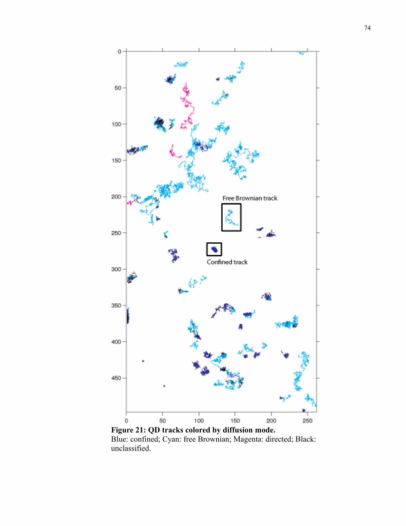
74
Figure 21: QD tracks colored by diffusion mode. Blue: confined; Cyan: free Brownian; Magenta: directed; Black: unclassified.
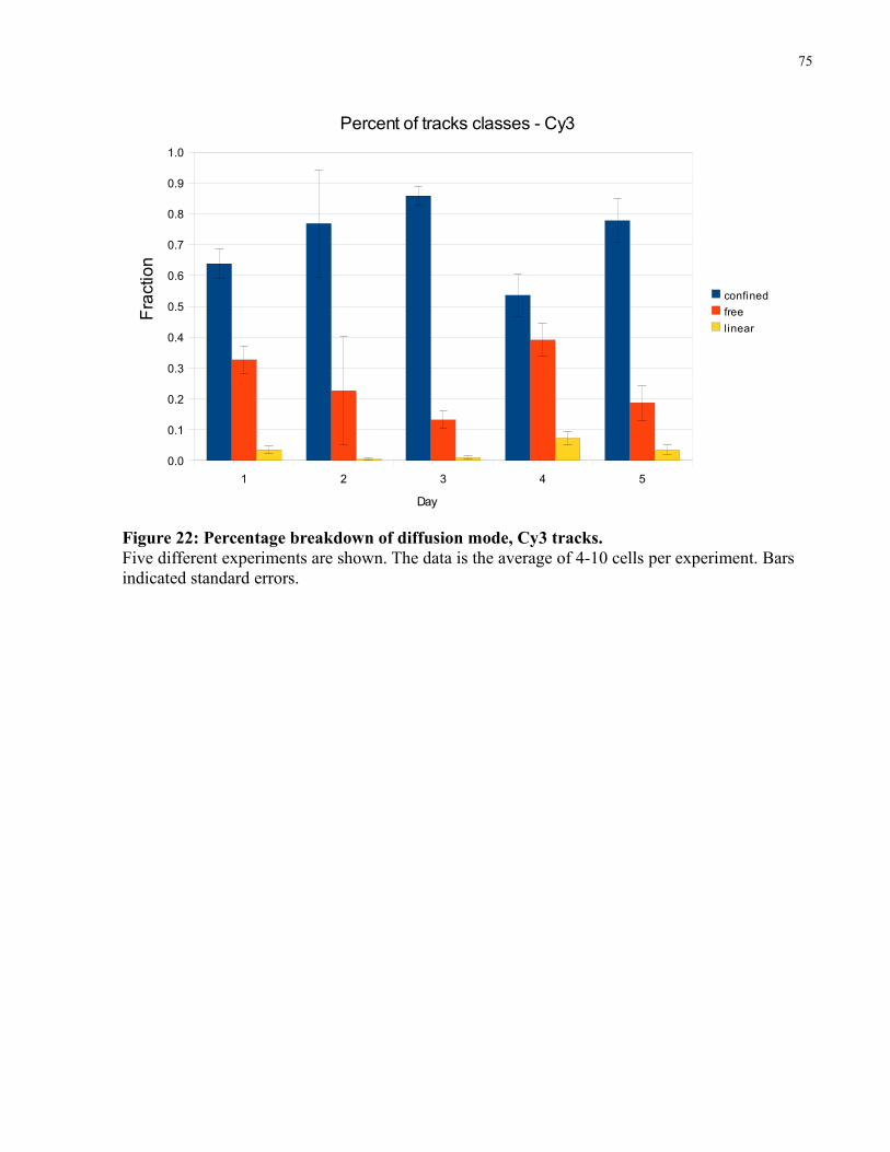
75
Figure 22: Percentage breakdown of diffusion mode, Cy3 tracks. Five different experiments are shown. The data is the average of 4-10 cells per experiment. Bars indicated standard errors.
1 2 3 4 50.0
0.1
0.2
0.3
0.4
0.5
0.6
0.7
0.8
0.9
1.0
Percent of tracks classes - Cy3
confinedfreelinear
Day
Frac
tion

76
Figure 23: Percentage breakdown of diffusion mode, QD tracks. Three different experiments are shown. The data are the average of 10-12 cells per experiment. Bars indicate standard errors.
1 2 30.0
0.1
0.2
0.3
0.4
0.5
0.6
0.7
confinedfreeliner
Day
Frac
tion
Percent of tracks classes - QDs
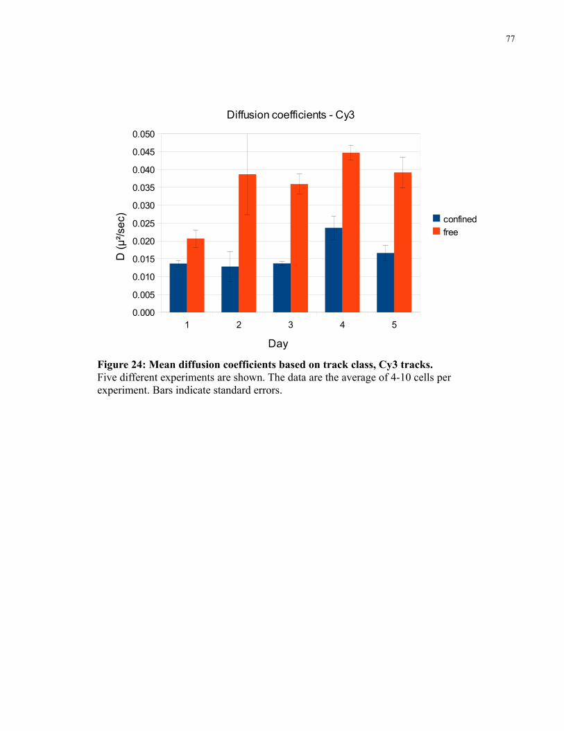
77
Figure 24: Mean diffusion coefficients based on track class, Cy3 tracks. Five different experiments are shown. The data are the average of 4-10 cells per experiment. Bars indicate standard errors.
1 2 3 4 50.000
0.005
0.010
0.015
0.020
0.025
0.030
0.035
0.040
0.045
0.050
confinedfree
Day
D (μ
²/sec
)Diffusion coefficients - Cy3

78
Figure 25: Mean diffusion coefficients based on track class, QD tracks. Three different experiments are shown. The data are the average of 10-12 cells per experiment. Bars indicate standard errors.
1 2 30.000
0.020
0.040
0.060
0.080
0.100
0.120
confinedfree
Day
D (μ
m²/s
ec)
Diffusion coefficients - QDs

79
Figure 26: Mean confinement region, Cy3 confined tracks. Five different experiments are shown. The data are the average of 4-10 cells per experiment. Bars indicate standard errors.
1 2 3 4 50
50
100
150
200
250
Day
Con
finem
ent r
egio
n (n
m)
Confinement region - Cy3

80
Figure 27: Mean confinement region, QD confined tracks. Three different experiments are shown. The data are the average of 10-12 cells per experiment. Bars indicate standard errors.
1 2 30
20
40
60
80
100
120
140
160
180
200
Day
Con
finem
ent r
egio
n (n
m)
Confinement region - QDs

81
Figure 28: Confinement region is not affected by positional accuracy: Mean positional accuracy of confined tracks from 10 QD-tracked cells (day 1) are plotted against the tracks' confinement region. The correlation between the sets is 0.04, suggesting that the confinement region reported is not an artifact of the positional accuracy.
0 100 200 300 400 500 600 700 800 9000
50
100
150
200
250
300
350
Confinement region vs positional accuracy
Confinement region (nm)
Pos
ition
al a
ccur
acy,
x-a
xis (n
m)
82
3.4 Involvement of the cytoskeletonIn order to better understand the components affecting the diffusion of FcγRIIa we studied
the effect of latrunculin B, an actin destabilizing agent. As seen in figure 29, latrunculin B
increased the fraction of mobile receptors compared to control cells. The effect is small (~20%
reduction in confined tracks, p-value 0.008) but consistent across days. Since tracking
experiments are carried out on flat portions of cells and since cells treated with latrunculin B tend
to retract and finally detach, a partial effect of latrunculin B on the actin network is expected.
This effect is consistent with previous results obtained for other receptors102,93.
Figure 30 and table 6 show the mean diffusion coefficient of each diffusion class in control
and latrunculin B-treated cells. In contrast with most reports92,93, latrunculin B did not affect the
diffusion coefficient of the different modes. This discrepancy is most likely due to the fact that
most studies do not report diffusion coefficients based on the diffusion mode, but an average for
all molecules before/after treatment. As seen in table 6, when all the tracks are taken into account
without classification based on diffusion mode, similar results are observed with an increase in
the mean diffusion coefficient after latrunculin B treatment. Since latrunculin B increases the
proportion of the freely-diffusing receptors, it will increase the overall diffusion coefficient.
Latrunculin B did not have an effect on compartment size for confined FcγRIIa tracks
(figure 31). This, again, is inconsistent with previous literature employing latrunculin B96 or
cytochalasin D41 in order to disrupt the actin mesh work. The differences may arise from the
nature of the observed molecule or the different cell type. It has been reported that different cell
types exhibit unique membrane-associated actin cytoskeleton architecture103, which correlates
with their different diffusion properties41. As no similar experiments had been conducted on
primary human macrophages it is hard to compare the results of our experiments with those
reported by others. It is worth noting that large differences exist in the response of the primary

83
macrophages used in this project and RAW247cells (a murine macrophage cell line routinely
used in our laboratory) to different actin disrupting agents.

84
Figure 29: Effect of latrunculin B on diffusion mode.Latrunculin B increases the proportion of free Brownian tracks compared to confined ones. Data are averages of three independent experiments (10-12 cells each, ~2000-3000 tracks per experiment). Bars represent standard errors. P-value = 0.008
Confined Free Linear0
0.1
0.2
0.3
0.4
0.5
0.6
ControlLatBFr
actio
nLatrunculin B effect on diffusion mode
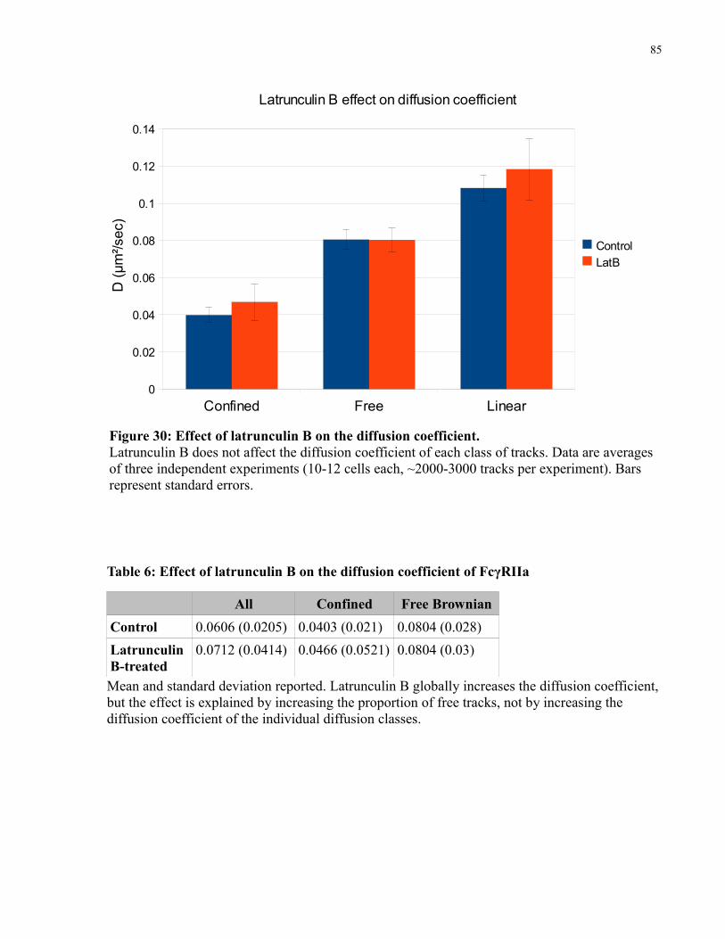
85
Table 6: Effect of latrunculin B on the diffusion coefficient of FcγRIIa
All Confined Free BrownianControl 0.0606 (0.0205) 0.0403 (0.021) 0.0804 (0.028)Latrunculin B-treated
0.0712 (0.0414) 0.0466 (0.0521) 0.0804 (0.03)
Mean and standard deviation reported. Latrunculin B globally increases the diffusion coefficient, but the effect is explained by increasing the proportion of free tracks, not by increasing the diffusion coefficient of the individual diffusion classes.
Figure 30: Effect of latrunculin B on the diffusion coefficient. Latrunculin B does not affect the diffusion coefficient of each class of tracks. Data are averages of three independent experiments (10-12 cells each, ~2000-3000 tracks per experiment). Bars represent standard errors.
Confined Free Linear0
0.02
0.04
0.06
0.08
0.1
0.12
0.14
ControlLatB
D (μ
m²/s
ec)
Latrunculin B effect on diffusion coefficient

86
Figure 31: Latrunculin B does not affect the confinement region of confined tracks. Data is average of three independent experiments (10-12 cells each, ~2000-3000 tracks per experiment). Bars represent standard errors.
control LatB0
20
40
60
80
100
120
140
160
180C
onfin
emen
t Reg
ion
(nm
)

87
4 DiscussionThe purpose of this project was to initiate a single-molecule study of FcγRIIa diffusion in
human macrophages and investigate receptor dynamics in relation to phagocytosis. To this end
the labeling strategy, acquisition setup and software parameters were optimized and applied to
the study of the basic behaviour of the receptor. Clustering analysis revealed that the receptor
exists mostly in a monomeric form. Diffusion analysis of the receptor revealed the existence of
two populations of receptors – freely mobile and confined, with no directed motion observed.
The diffusion coefficients of the freely mobile and confined receptors are 0.08 μm2/s and 0.04
μm2/s and the confinement area of the confined particles is 150 nm. The confinement could be
partially released by mild disruption of the actin cytoskeleton, suggesting an involvement in the
mechanism of confinement, while neither the diffusion coefficient nor the confinement area
changed in response to actin disruption.
4.1 Aggregation state of FcγRIIaIt has been previously reported that FcγRIIa may exist as a dimeric species, potentially
priming the receptor for efficient activation. This hypothesis was based on two main findings.
The first crystal structure reported showed a dimer interface at the D2 extracellular domain19
while a subsequent study used a protein complementation assay to address the question and
concluded that the receptor exists as a dimeric form20. As far as the structural evidence is
concerned, a second crystallographic study comparing ligand-binding by different FcγRs21
concluded that the original reported dimer interface was due to crystal packing and suggested the
receptor is indeed monomeric. In the second report the researchers constructed FcγRIIa chimeras
with either the DHFR[1,2] or the DHFR[3] fragments for use in a DHFR complementation assay.

88
As a control, an FcαRI-DHFR[1,2] construct was co-transfected with the FcγRIIa-DHFR[3] to
eliminate the possibility of DHFR-mediated dimer formation. Through both survival and
fluorescence assays the two FcγRIIa constructs exhibited DHFR complementation, while the
control condition did not, leading to the conclusion that FcγRIIa can form homotypic non-
covalent dimers. The researchers then constructed an S129P mutated FcγRIIa predicted to disrupt
the dimer interface found in the original crystal structure19 and showed that cellular activation is
reduced while ligand binding is unchanged. A few issues exist with these experiments: First, the
choice of proline as a mutated residue is surprising due to its rigid cyclic structure known to
disrupt secondary structures. As the mutation is in the C' strand of the D2 domain (an Ig-fold
domain) it is likely to disrupt its structure and consequently ligand binding. S129P was not
included in a number of mutated receptors compared in the initial crystal study and its
conformational impact was not assessed before. Second, the researchers never presented the
dimerization state of the S129P mutant using the DHFR assay, a surprising omission in a paper
concluding that “The inability of FcRIIa-S129P to signal efficiently (despite no loss of IgG
binding) implies that FcRIIa self-association is required for optimal function“20. In light of the
lack of data in the literature, we employed a different methodology and investigated the size of
the receptor complex in the resting state. Our results support a monomeric form to be the
predominant one, in line with the second structural paper mentioned21.
All activating FcRs , excluding FcγRIIa, exist as non-covalent complexes with the dimeric
γ-chain, giving rise to a dimeric ITAM as the smallest signaling unit. While FcγRIIa may
associate with the γ-chain104, it is capable of mediating its function independently, as is the case
when transfected into cell lines devoid of endogenous γ-chain. FcγRIIa is therefore unique in
having a single ITAM; the functional implications of this difference and consequently, the
consequences of complex formation between un-ligated receptors, are yet unknown.
89
Raft association
The involvement of lipid micro-domains in FcγRIIa signaling has been suggested in the
past34. It is proposed that Src-family kinases such as Lyn associate with micro-domains by virtue
of their acylated tails, to which the receptors are recruited upon cross-linking. The fact that
FcγRIIa mutated in its TM domain in a manner that precludes association with lipid micro-
domains does not induce activation supports this hypothesis34. As discussed above, the majority
of research regarding lipid micro-domains involves biochemical isolation of buoyant fractions
combined with micro-domain disruption by cholesterol extraction, a methodology that has long
been criticized43. An alternative hypothesis addressing the existence of lipid micro-domains
suggests that receptor clustering induces their formation, rather than causing translocation of the
clustered receptors to a pre-formed domain105. Such clustered receptors, by virtue of their
particular TM domain structure, allow better packing of the long unsaturated chains and
cholesterol found in micro-domains. This hypothesis is equally supported by the experiments
mentioned, as mutations to the TM domain may reduce its propensity for long-chain packing and
the induction of the micro-domain. The initial cluster size of FcγRIIa may have an effect on the
raft association or induction process, presumably requiring more monomeric receptors to cluster,
compared to the case of dimeric ones, therefore modulating the recruitment of Src-kinases and
the initiation of signaling. The contribution of rafts to FcγRIIa diffusion/confinement was not
tested in this thesis and remains the subject of future experiments.
Ligand-induced dimerization
A second possible implication of FcγIIa cluster size is the potential for ligand-induced
clustering. The BCR is an example of another ITAM-dependent receptor that requires clustering
in order to induce cell activation. While many of its ligands are multimeric and can therefore
90
induce clustering, other ligands are monomeric or sparse. It has been shown106 for the BCR that
binding of monomeric ligands can induce mIgM self-association via interactions of its C4
domain, leading to ligand-induced dimerization not requiring multi-valent ligands (the BCR TM
chain is essentially a transmembrane immunoglobulin, mIgM). It is possible that similar
mechanisms are in place for FcγRIIa, allowing self-association following ligand binding
regardless of ligand valency. It has been shown by gel filtration analysis that soluble FcγRIIa can
bind to its ligand with a 2:1 stoichiometry107. While the proposed model suggested binding of
two receptors directly to the ligand, the alternative of ligand-induced dimerization was not
addressed. Though most biological targets for FcγRs are in fact multivalent, the possibility of
potentiating stronger lateral interactions among receptors in order to stabilize the cluster exists.
Such a mechanism can support faster propagation of signaling and allow for a more sensitive
response, especially at the early stages of infection, when specific antibody titers and density are
relatively low. If a mechanism for inducing dimeric FcγRIIa exists, it may explain the small
dimeric population observed, as random and unstable exposure of the interface may happen
without ligand binding, becoming locked or at least stabilized upon binding.
Effect of cluster size on diffusion.
Insofar as receptor aggregation and mobility are addressed, it has been shown for other
proteins that lateral mobility is reduced, to the point of immobilization, upon unstimulated
aggregation97, a phenomenon termed 'oligomerization-induced trapping'.
Since the diffusion of a monomeric species is expected to be faster than that of a dimeric
one, the existence of a mostly monomeric population may allow greater freedom for the receptor
to reach the site of attachment and participate in signaling. In line with this notion is the diffusion
coefficient of the mobile population, which is at the high-end of the published literature

91
regarding receptor mobility (0.08 μm2/s; literature values span orders of magnitude, but rarely go
above 0.1 μm2/s for TM receptors). The importance of receptor mobility is further discussed
below. It is interesting to note that similar studies performed on murine FcγRI and III in our
laboratory (unpublished observations) show a larger proportion of confined tracks compared with
FcγRIIa, potentially arising from the increased size of the intracellular domain, though
differences due to cell type cannot be excluded.

92
4.2 Diffusion of FcγRIIa in the basal stateEven though mobility measurements exist for different immune receptors, little attention
have been given to the diffusion of FcγRIIa. Such information is of high importance as receptor
clustering is necessary for activation. The first estimate of FcγRIIa diffusion was established
using FRAP experiments108 and gave a diffusion coefficient of 13.9x1010 cm2/sec (0.13 μm2/sec)
with a mobile fraction of ~50%, similar results to the ones obtained here.
Confinement vs. tethering
The classification of a track as confined comes from the MSS or MSD analysis, and is
purely a mathematical description of the motion. As is obvious from experiments with particles
on coverslips, an immobile particle tracked over a period of time is classified as confined, even
though it is completely immobile (and not, as the designation 'confined' suggests, diffusing
within a corral). This artifact arises from the noise inherent in the system, leading to slight
differences in the PSF fit that appear as particle movement. Furthermore, in the cellular context,
a biological molecule tethered to a linker will have some degree of freedom in its position and
can be identified as confined, though in reality it is tethered. In some cases researchers
distinguish between the two modes97, but mostly they are treated as one.
Though both confined and tethered tracks are immobile over the long range, the biological
implications of receptor immobility differ greatly depending on the mechanism of restriction. A
molecule freely diffusing within a corral may not escape due to a large cytoplasmic tail
interfering with its movement, a rigid local cytoskeleton or association with lipid micro-domains,
to name a few possibilities. A tethered molecule, on the other hand, is physically attached to
another component, often the cytoskeleton, directly or via linker proteins (figure 32). The

93
biological control of such immobility and the transition between states will differ greatly for the
two scenarios. It has been shown for the CFTR protein that a functional PDZ binding motif in its
intracellular domain is required for immobilization109. Masking of the binding domain released
the receptor from confinement, independent of any other treatment, suggesting a mechanism for
protein-specific mobility regulation. On the other hand, restriction of protein mobility by actin
has been shown for numerous receptors. For example, FcεRI is immobilized by actin following
cell activation102. Control of actin dynamics can therefore serve to affect protein diffusion and as
a mechanism for trapping or releasing proteins, regardless of direct anchoring. An example of
such control has been shown for the glycine receptor, which can be directly released from
synaptic clusters by actin dissociation prior to the dispersion of the cluster's main scaffold
protein, gephyrin110. The undiscriminating nature of control via cytoskeleton regulation may
affect unrelated TM proteins but, as is the case in phagocytosis, chemotaxis, cell-adhesion and
other cytoskeletal-dependent processes, actin dynamics can be precisely controlled both spatially
and temporally. Thus, the distinction between tethering and confinement is important for
deciphering the underlying mechanism of receptor immobility and is a pre-requisite for
understanding its control.

94
Figure 32: Immobility due to confinement vs. tethering. A confined receptor (A) is mobile within the corral boundaries. For illustration, the corral is drawn as an actin meshwork but the biological corral may be due to a microtubule network, lipid microdomains, etc. A tethered receptor (B) does not diffuse but may have some degree of freedom around the tethering molecule. The illustration shows tethering to the cytoskeleton via a linker protein (depicted by the blue hexagon). The control of receptor immobility would differ greatly between the two cases.

95
In order to distinguish between the two mechanisms accounting for immobility, confined
tracks were compared with immobilized particles. The parameters are shown in table 7 and
figure 33. As can be seen, immobilized particles are detected with a diffusion coefficient an order
of magnitude lower than that of FcγRIIa confined tracks, and in a confinement area ~7 times
smaller. While those two parameters are routinely used97,101 for distinguishing immobile from
confined tracks, a second method was employed to determine whether the observed confinement
area is an artifact of the positional determination. The confinement area of each confined track
was compared to the mean uncertainty in positional determination along the track. Since the
apparent confinement region of immobile (or tethered) particles is an artifact of the positional
uncertainty (and to some extent of the tethering “freedom”), it should correlate to the uncertainty.
For immobilized particles a weak but significant correlation exists (0.76, P<0.05 for Cy3; 0.46,
p<0.05 for QDs). Confined FcγRIIa tracks, on the other hand, showed no correlation (correlation
coefficient of 0.04). Combined, the increased diffusion coefficient, confinement area and lack of
correlation to the positional uncertainty support the notion that the reported confinement area is
due to real motion, rather than being an artifact of the detection process.
Table 7: Parameters of immobilized particles and FcγRIIa confined tracks.
Mean Diffusion Coefficient (μm2/s)
Mean Confinement Area (nm)
Correlation of area to positional uncertainty
Immobilized Cy3 0.008 98 0.76Immobilized QDs 0.001 21 0.46Tracked FcγRIIa 0.04 148 0.04

96
Figure 33: Comparison of immobile QDs and tracked QD-labeled
FcγRIIa.
Diffusion coefficient (A), confinement region (B) and correlation of confinement region to positional uncertainty (C) are shown for monodisperse QD attached to a coverslip (left), and QD-labeled FcγRIIa tracked in cells (right).

97
Two populations vs. two states
The observation that roughly half the receptors are confined and half freely mobile is of
large significance. The first question is whether two distinct, long-lasting populations of
receptors exist or whether the receptors can freely switch between the two states. The best
methodology, qualitatively and quantitatively, for assessing transient confinement is to use a
'rolling-window' analysis111, in which an analysis window of certain length is 'rolled' through the
whole track and the track portions are analyzed as independent tracks. The resulting diffusion
mode of each segment can identify periods of transition from mobility to
confinement/immobility. Such functionality has only recently been introduced to our software
and its parameters have not yet been optimized. Some of the considerations for use of a rolling
window analysis include:
• Transition time: If the transition time between the two diffusion modes is shorter than the
window, it will not be detected. For MSS analysis a minimum of 20 frames is required,
correlating to 600 ms in the case of video-rate imaging. If receptors are transiently
confined for shorter periods they will likely fail to be detected.
• Gaps: periods of gaps cannot be analyzed for molecular motions. Closing gaps is one of
the softwares' strongest advantages, yet the process poses big challenges when more in-
depth analysis is required. Whenever gaps exist in the track much of the data regarding
the transient behaviour will be missing. This can be circumvented to some extent by
using tracking parameters that reduce gap-closing, but such manipulation will inherently
lead to shorter tracks and a lower likelihood of observing transient behaviours.
A number of receptors, including FcγRIIa, have been reported to exist in both mobile and
immobile states112,108 via FRAP and SPT experiments, but in most cases those findings are based
98
on a change in the total free or immobile fraction, rather than following single trajectories. In a
few studies that inspected individual trajectories a switch has been seen between the two states of
the same receptor113,109, though such observations are usually qualitative and not quantitative and
based on a small number of observations. In at least one study113 such temporary immobility was
observed to recruit Lyn and Gα and to induce Lyn activation at the immobile cluster. By visually
inspecting FcγRIIa diffusion we have observed a number of receptors switching their motion
type, though others are completely immobile or fully mobile.
Long-lasting immobility generally arises via anchoring to cytoskeletal components directly
or via linker proteins, as is the case for CFTR109. Our results, however, do not support a tethering
model, and a prolonged confinement is the next possible explanation. Such long-lasting
confinement usually exists at sites of macromolecular complex formation. It is possible that such
periods of FcγRIIa immobility take place at sites of macromolecular aggregation and serve as
'hot spots' for activation. While other FcγRs as well as the BCR and TCR associate with
accessory proteins via their TM domains, those interactions are based on the mildly
polar/charged nature of their TM domain, a characteristic missing in FcγRIIa. To date, no protein
interactions have been reported for inactive FcγRs, though basal colocalization of murine FcγRI
with both Hck (a SFK similar to Lyn) and F-actin was recently reported105. While all currently
known protein interactions with FcγRIIa take place via the receptor's phosphorylated ITAM
following activation, transient interactions via the extracellular, cytoplasmic or the TM domain
may exist. Yet the most plausible explanation for the existence of confined population is their
trapping in actin-rich domains, a concept supported by the increase in the mobile fraction upon
latrunculin B treatment. Such actin-rich domains may exist randomly through the cell or may be
caused by basal, low-level receptor activation due to transient interactions with Lyn. Such an
activation level is not strong enough to induce activation and phagocytosis, since no extensive

99
receptor clustering takes place. As will be discussed below, a constitutive basal level of actin
dynamics probably exists in macrophages and may be the mechanism underlying such
confinement areas.
Importance of immobility
The balance between mobile and confined receptors may have implications for efficient
particle binding and internalization. Unpublished experiments carried out in our laboratory with
the murine macrophage RAW247 cell line show that, in parallel to increased receptor mobility
due to latrunculin B or jasplakinolide treatment, a reduction in particle binding takes place.
Furthermore, treatment with blebbistatin (a myosin II inhibitor) reduced receptor mobility and
increased particle binding. These findings are somewhat counter-intuitive, as one would expect
receptor aggregation and ligand binding to increase with increased mobility. Surprisingly, pre-
treatment with blebbistatin followed by jasplakinolide decreased both receptor mobility and
particle binding (the results are summarized in table 8).
Table 8: Effect of actin perturbation on particle binding and receptor mobility
Treatment Effect on mobility Effect on particle bindingLatrunculin B + -Jasplakinolide + -Blebbistatin - +Blebbistatin followed by Jasplakinolide - -
These surprising results suggest that particle binding is not affected by receptor mobility but
rather by the presence of a dynamic cytoskeleton, as both an increase (latrunculin B and
jasplakinolide) and a decrease (blebbistatin followed by jasplakinolide) in receptor mobility

100
result in decreased particle binding, while any of the conditions affecting actin dynamics reduced
binding. Similar binding results were recently published along with experiments showing the
importance of active tyrosine kinases for binding105, suggesting that binding itself, and not only
internalization, is an active process. Insofar as binding and actin dynamics are concerned,
macrophages seem to constitutively probe their surrounding with actin-dependent membrane
extensions (unpublished observations in RAW247 macrophages). Furthermore, basal tyrosine
phosphorylation is usually seen in macrophages114. It is likely that such on-going surveillance is
dependent on actin dynamics and a basal level of activation of the actin machinery. Though actin
dynamics are important for particle binding, there is still a need for receptor clustering and
therefore mobility in order to induce phagocytosis.
While particle uptake is also diminished under actin-perturbing treatments similar to the
ones affecting binding, the level of tyrosine phosphorylation is unchanged114, suggesting that
phagocytic inhibition caused by actin disruption is a downstream effect, rather than one related
to initial receptor phosphorylation. It would be interesting to investigate the receptor and
downstream proteins phosphorylation state under conditions that increase or decrease FcγRIIa
mobility. Such experiments can shed light on the importance of receptor mobility vs. immobility
to signal initiation and propagation. An intriguing possibility is the need for a balance between
immobile receptors confined in actin-rich corrals, potentially in the vicinity of other signaling
components such as Lyn, and mobile ones that are required for cluster formation. A decrease in
the immobile population may reduce the ability of the cells to activate by producing a shortage of
'signaling platforms', while a decrease in the mobile population may diminish the availability of
receptors that can cluster.

101
Control of receptor movement via signaling to actin
It has long been reported that disruption of the cytoskeleton architecture increases receptor
mobility, though in some instances mixed reports exist102. With the recent hop-diffusion
framework, an explanation to this phenomenon presents itself at the molecular level93; an
increased compartment size may be the basis for the increased diffusion coefficient.
Nevertheless, other mechanisms are in place and affect receptor diffusion: aggregation, ligand
binding, cytoskeletal binding and association with coated pits or caveolae can all alter lateral
mobility.
Since latrunculin B treatment did not alter the diffusion coefficients of tracks when the
diffusion mode of the particle was taken into account, the effect of the drug on FcγRIIa seems to
be one of releasing the receptor from confinement, rather than a global increase in diffusion
coefficient. Such release from confinement in response to actin de-polymerization can have a
significant biological role in affecting receptor clustering or, on the other hand, may restrict its
mobility once a particle is bound. As discussed above, actin-based basal confinement may serve
to bring receptors to the proximity of other necessary signaling components and create activation
'hot-spots'. Another mechanism by which actin may influence phagocytosis is more local and
activation-driven. Following the initial receptor clustering actin is extensively polymerized at the
site of receptor engagement, potentially leading to receptor entrapment in the vicinity. For
example, experiments on different receptors suggest that jasplakinolide increases the number of
barriers in the diffusion path and reduces the diffusion coefficient115. An elegant model was
recently suggested for the inclusion or exclusion of receptors in neuronal synaptic membranes. It
was shown that an increase in neuronal activity correlating with long-term-potentiation (LTP, a
process involving an increase in synaptic receptor density) increased AMPA receptor mobility in
extra-synaptic membranes116. In agreement, a protocol used to induce long-term-depression

102
(LTD, a process involving a loss of receptors from the synapse) leads to increased AMPA
receptor diffusion specifically in the synaptic density region117. A third paper investigating the
effect of actin and microtubule on glycine receptor mobility found that latrunculin B increased
the diffusion throughout the neuronal membrane while nocodazole increased the mobility only at
extra-synaptic regions110. The researchers suggested that differential control of the actin and
microtubule cytoskeleton may modulate the influx and outflux of receptors to and from the
synapse, suggesting a molecular pathway of LTP and LDP control of synaptic density. An
analogous mechanism may exist for FcγRs clustering: initial receptor clustering will trap more
receptors at the sites of actin polymerization. Since the effect is local, receptors from other
membrane areas are capable of freely diffusing, but once in proximity to the advancing actin
meshwork their diffusion is reduced and the chance of participating in signaling increases. This
mechanism is in line with the 'zipper' model118: as receptors at the advancing pseudopods are
trapped and engage more ligands, a wave of signaling progresses with the pseudopods. While the
importance of actin is most strikingly seen in the need to advance the pseudopods, it may equally
have a role in stabilizing the receptors in place.
4.3 Future DirectionsThe importance of receptor clustering for signal initiation during phagocytosis has been long
known, yet little has been discovered regarding the mechanism for such clustering. With the
advancements in new microscopic technologies more information can be gleaned regarding
receptor mobility and dynamics. Such information will pave the way to a fuller understanding of
receptor clustering and dynamics. Among the many unknowns in the process of phagocytosis are
the upstream dynamics of clustering – the timing for recruitment of individual receptors, the
critical cluster size for initiation of signaling and the mechanism for ligand size discrimination

103
are a few examples. The timing of the process and its dependence on particle size can be
investigated using similar techniques to the ones utilized in this thesis, following the
incorporation of individual receptors to a forming cluster and potentially using chimeric proteins
(for example, Syk-GFP) as reporters for signaling progression. Whether clustering is a
cooperative process is also a mystery and may be addressed by visualizing the dynamics of
receptor recruitment to a forming cluster.
The mechanism for size discrimination (allowing for ubiquitylation- and clathrin-dependent
endocytosis of small immune complexes and actin-dependent phagocytosis of large particles) is
also not known. While the importance of receptor ubiquitylation for endocytosis has been shown,
some conflicting reports exist regarding the timing and signaling progression. Ubiquitylation was
shown to be independent of receptor phosphorylation119 yet a potential ubiquitin ligase (c-Cbl)
implicated in down-regulating FcγRIIa signaling120 in neutrophils was shown to interact with
active Syk121, a downstream event in signaling. Whether c-Cbl is also the ubiquitin-ligase
involved in endocytosis is not known. Regardless of the ligase identity, the mechanism for size
discrimination must be highly dynamic in order to prevent signal termination during the
transition from small to large receptor clusters, yet allow fast and efficient uptake of small
immune complexes. In order to decipher the relationships between the different components and
the mechanism for discriminating small from large clusters, the different components can be
followed with high temporal resolution and their sequential or parallel recruitment to clustered
FcγRs mapped.
As was mentioned in the Discussion, while particle internalization and, as recently found in
our laboratory, particle binding, depend on the presence of a dynamic cytoskeleton, the initial
signaling steps do not114. It is interesting to speculate whether the dynamics of signal initiation
would be altered when receptor mobility is affected. To this end, actin-perturbing agents can be

104
used to affect receptor mobility and the progression of signaling, such as ITAM phosphorylation,
Syk recruitment and activation etc., can be followed microscopically. Such experiments will
elucidate the importance of receptor lateral mobility for activation dynamics, a topic which is yet
unvisited.
In conclusion, the study of receptor clustering and co-clustering and its downstream effects
is in its infancy. Methodologies utilizing high spatial and, importantly, temporal resolution are a
necessity in order to decipher such dynamic processes. The utilization of single-molecule
microscopy techniques will help in elucidating some of the mysteries relating to the initiation of
phagocytosis and its most upstream signaling processes, paving the way for a fuller
understanding of the process.

105
References or Bibliography
1. Underhill, D.M. & Ozinsky, A. Phagocytosis of microbes: complexity in action. Annu. Rev.
Immunol 20, 825-852(2002).
2. Plüddemann, A., Mukhopadhyay, S. & Gordon, S. The Interaction of Macrophage
Receptors with Bacterial Ligands. Expert Reviews in Molecular Medicine 8, 1-25(2006).
3. Campagne, M.V.L., Wiesmann, C. & Brown, E.J. Macrophage complement receptors and
pathogen clearance. Cellular Microbiology 9, 2095-2102(2007).
4. Naito, M. et al. Development, differentiation, and phenotypic heterogeneity of murine
tissue macrophages. J Leukoc Biol 59, 133-8(1996).
5. Naito, M., Hasegawa, G. & Takahashi, K. Development, differentiation, and maturation of
Kupffer cells. Microscopy Research and Technique 39, 350-364(1997).
6. KAPLAN, G. Differences in the Mode of Phagocytosis with Fc and C3 Receptors in
Macrophages. Scandinavian Journal of Immunology 6, 797-807(1977).
7. Hall, A.B. et al. Requirements for Vav Guanine Nucleotide Exchange Factors and Rho
GTPases in FcγR- and Complement-Mediated Phagocytosis. Immunity 24, 305-316(2006).
8. Swanson, J.A. Shaping cups into phagosomes and macropinosomes. Nat Rev Mol Cell Biol
9, 639-649(2008).
9. Wu, Y., Tibrewal, N. & Birge, R.B. Phosphatidylserine recognition by phagocytes: a view
to a kill. Trends Cell Biol 16, 189-197(2006).
10. Zhou, Z. New phosphatidylserine receptors: clearance of apoptotic cells and more. Dev.
Cell 13, 759-760(2007).
11. Ehlenberger, A.G. & Nussenzweig, V. The role of membrane receptors for C3b and C3d in
phagocytosis. J. Exp. Med 145, 357-371(1977).
12. Tohyama, Y. & Yamamura, H. Complement-mediated phagocytosis--the role of Syk.
IUBMB Life 58, 304-308(2006).

106
13. Berken, A. & Benacerraf, B. PROPERTIES OF ANTIBODIES CYTOPHILIC FOR
MACROPHAGES. J. Exp. Med. 123, 119-144(1966).
14. Barclay, A.N. Membrane proteins with immunoglobulin-like domains--a master
superfamily of interaction molecules. Seminars in Immunology 15, 215-223(2003).
15. Ravetch, J.V. Fc receptors. Current Opinion in Immunology 9, 121-125(1997).
16. Looney, R.J., Abraham, G.N. & Anderson, C.L. Human monocytes and U937 cells bear two
distinct Fc receptors for IgG. J. Immunol 136, 1641-1647(1986).
17. Hulett, M.D. et al. Multiple regions of human Fc gamma RII (CD32) contribute to the
binding of IgG. J Biol Chem 270, 21188-94(1995).
18. Barnes, N. et al. Raft localisation of Fc[gamma]RIIa and efficient signaling are dependent
on palmitoylation of cysteine 208. Immunology Letters 104, 118-123(2006).
19. Maxwell, K.F. et al. Crystal structure of the human leukocyte Fc receptor, Fc[gamma]RIIa.
Nat Struct Mol Biol 6, 437-442(1999).
20. Powell, M.S. et al. Alteration of the FcgammaRIIa Dimer Interface Affects Receptor
Signaling but Not Ligand Binding. J Immunol 176, 7489-7494(2006).
21. Sondermann, P., Kaiser, J. & Jacob, U. Molecular Basis for Immune Complex Recognition:
A Comparison of Fc-Receptor Structures. Journal of Molecular Biology 309, 737-
749(2001).
22. Molecular basis for a polymorphism of human Fc gamma receptor II (CD32). J Exp Med.
172, 19–25(1990).
23. Tan, S.Y. FcgammaRIIa polymorphism in systemic lupus erythematosus. Kidney Blood
Press Res 23, 138-42(2000).
24. Belostocki, K. et al. Infliximab treatment shifts the balance between stimulatory and
inhibitory Fcgamma receptor type II isoforms on neutrophils in patients with rheumatoid
arthritis. Arthritis Rheum 58, 384-8(2008).
107
25. Forthal, D.N. et al. FcgammaRIIa genotype predicts progression of HIV infection. J
Immunol 179, 7916-23(2007).
26. Forthal, D.N. et al. Recombinant gp120 Vaccine-Induced Antibodies Inhibit Clinical Strains
of HIV-1 in the Presence of Fc Receptor-Bearing Effector Cells and Correlate Inversely
with HIV Infection Rate. J Immunol 178, 6596-6603(2007).
27. Ferrante, A., Beard, L.J. & Feldman, R.G. IgG subclass distribution of antibodies to
bacterial and viral antigens. Pediatr. Infect. Dis. J 9, S16-24(1990).
28. Ravetch, J.V. & Kinet, J.P. Fc receptors. Annu. Rev. Immunol 9, 457-492(1991).
29. Janeway, C. Immunobiology: The Immune System in Health and Disease. (Taylor & Francis
Group; Garland Science: 2005).
30. Abastado, J. et al. Dimerization of soluble major histocompatibility complex-peptide
complexes is sufficient for activation of T cell hybridoma and induction of
unresponsiveness. J. Exp. Med. 182, 439-447(1995).
31. Dal Porto, J.M. et al. B cell antigen receptor signaling 101. Molecular Immunology 41, 599-
613(2004).
32. Ibarrola, I. et al. Influence of tyrosine phosphorylation on protein interaction with
Fc[gamma]RIIa. Biochimica et Biophysica Acta (BBA) - Molecular Cell Research 1357,
348-358(1997).
33. Bewarder, N. et al. In vivo and in vitro specificity of protein tyrosine kinases for
immunoglobulin G receptor (FcgammaRII) phosphorylation. Mol. Cell. Biol 16, 4735-
4743(1996).
34. Katsumata, O. et al. Association of FcgammaRII with Low-Density Detergent-Resistant
Membranes Is Important for Cross-Linking-Dependent Initiation of the Tyrosine
Phosphorylation Pathway and Superoxide Generation. J Immunol 167, 5814-5823(2001).
35. Greenberg, S. et al. Clustered syk tyrosine kinase domains trigger phagocytosis. Proc. Natl.
Acad. Sci. U.S.A 93, 1103-1107(1996).

108
36. Crowley, M.T. et al. A Critical Role for Syk in Signal Transduction and Phagocytosis
Mediated by Fcgamma Receptors on Macrophages. J. Exp. Med. 186, 1027-1039(1997).
37. Huang, Z. et al. Differential kinase requirements in human and mouse Fc-gamma receptor
phagocytosis and endocytosis. J Leukoc Biol 80, 1553-1562(2006).
38. Jongstra-Bilen, J. et al. Dual Functions of Bruton's Tyrosine Kinase and Tec Kinase during
Fcgamma Receptor-Induced Signaling and Phagocytosis. J Immunol 181, 288-298(2008).
39. Sohn, H.W., Tolar, P. & Pierce, S.K. Membrane heterogeneities in the formation of B cell
receptor-Lyn kinase microclusters and the immune synapse. J Cell Biol 182, 367-79(2008).
40. Bijlmakers, M. Protein acylation and localization in T cell signaling (Review). Mol Membr
Biol 26, 93-103(2009).
41. Murase, K. et al. Ultrafine membrane compartments for molecular diffusion as revealed by
single molecule techniques. Biophys. J 86, 4075-4093(2004).
42. Kusumi, A. et al. Single-molecule tracking of membrane molecules: plasma membrane
compartmentalization and dynamic assembly of raft-philic signaling molecules. Seminars
in Immunology 17, 3-21(2005).
43. Heerklotz, H. Triton promotes domain formation in lipid raft mixtures. Biophys J 83, 2693-
701(2002).
44. Kwik, J. et al. Membrane cholesterol, lateral mobility, and the phosphatidylinositol 4,5-
bisphosphate-dependent organization of cell actin. Proc Natl Acad Sci U S A 100, 13964-
9(2003).
45. Castellano, F., Chavrier, P. & Caron, E. Actin dynamics during phagocytosis. Seminars in
Immunology 13, 347-355(2001).
46. Hoppe, A.D. & Swanson, J.A. Cdc42, Rac1, and Rac2 Display Distinct Patterns of
Activation during Phagocytosis. Mol. Biol. Cell 15, 3509-3519(2004).
47. Groves, E. et al. Molecular mechanisms of phagocytic uptake in mammalian cells. Cell Mol
Life Sci 65, 1957-76(2008).

109
48. Steinberg, B.E. & Grinstein, S. Pathogen destruction versus intracellular survival: the role
of lipids as phagosomal fate determinants. J. Clin. Invest 118, 2002-2011(2008).
49. Yeung, T. & Grinstein, S. Lipid signaling and the modulation of surface charge during
phagocytosis. Immunological Reviews 219, 17-36(2007).
50. Oude Weernink, P.A., Schmidt, M. & Jakobs, K.H. Regulation and cellular roles of
phosphoinositide 5-kinases. European Journal of Pharmacology 500, 87-99(2004).
51. Hilpelä, P., Vartiainen, M.K. & Lappalainen, P. Regulation of the actin cytoskeleton by
PI(4,5)P2 and PI(3,4,5)P3. Curr. Top. Microbiol. Immunol 282, 117-163(2004).
52. Sun, H.Q. et al. Gelsolin, a Multifunctional Actin Regulatory Protein. J. Biol. Chem. 274,
33179-33182(1999).
53. Tomasevic, N. et al. Differential regulation of WASP and N-WASP by Cdc42, Rac1, Nck,
and PI(4,5)P2. Biochemistry 46, 3494-3502(2007).
54. Vieira, O.V. et al. Distinct roles of class I and class III phosphatidylinositol 3-kinases in
phagosome formation and maturation. J. Cell Biol. 155, 19-26(2001).
55. Chamberlain, M.D. et al. The p85alpha Subunit of Phosphatidylinositol 3'-Kinase Binds to
and Stimulates the GTPase Activity of Rab Proteins. J. Biol. Chem. 279, 48607-
48614(2004).
56. Pan, J. et al. Activation of Rac1 by phosphatidylinositol 3-kinase <i>in vivo</i>: role in
activation of mitogen-activated protein kinase (MAPK) pathways and retinoic acid-induced
neuronal differentiation of SH-SY5Y cells. Journal of Neurochemistry 93, 571-583(2005).
57. Satterthwaite, A.B., Li, Z. & Witte, O.N. Btk function in B cell development and response.
Seminars in Immunology 10, 309-316(1998).
58. Lee, W.L. et al. Role of CrkII in Fcgamma Receptor-mediated Phagocytosis. J. Biol. Chem.
282, 11135-11143(2007).
59. Miyano, K. & Sumimoto, H. Role of the small GTPase Rac in p22phox-dependent NADPH
oxidases. Biochimie 89, 1133-1144(2007).

110
60. Kamen, L.A. et al. SHIP-1 Increases Early Oxidative Burst and Regulates Phagosome
Maturation in Macrophages. J Immunol 180, 7497-7505(2008).
61. Kanai, F. et al. The PX domains of p47phox and p40phox bind to lipid products of PI(3)K.
Nat Cell Biol 3, 675-678(2001).
62. Yeung, T. et al. Receptor Activation Alters Inner Surface Potential During Phagocytosis.
Science 313, 347-351(2006).
63. Yeung, T. et al. Membrane Phosphatidylserine Regulates Surface Charge and Protein
Localization. Science 319, 210-213(2008).
64. Kooijman, E.E. et al. Modulation of Membrane Curvature by Phosphatidic Acid and
Lysophosphatidic Acid. Traffic 4, 162-174(2003).
65. Gu, H. et al. Critical role for scaffolding adapter Gab2 in FcgammaR-mediated
phagocytosis. J. Cell Biol. 161, 1151-1161(2003).
66. Kedzierska, K. et al. FcgammaR-mediated phagocytosis by human macrophages involves
Hck, Syk, and Pyk2 and is augmented by GM-CSF. J Leukoc Biol 70, 322-328(2001).
67. Nayal, A. et al. Paxillin phosphorylation at Ser273 localizes a GIT1-PIX-PAK complex and
regulates adhesion and protrusion dynamics. J. Cell Biol. 173, 587-589(2006).
68. Tridandapani, S. et al. The Adapter Protein LAT Enhances Fcgamma Receptor-mediated
Signal Transduction in Myeloid Cells. J. Biol. Chem. 275, 20480-20487(2000).
69. Griffin, F.M. et al. Studies on the mechanism of phagocytosis. I. Requirements for
circumferential attachment of particle-bound ligands to specific receptors on the
macrophage plasma membrane. J. Exp. Med 142, 1263-1282(1975).
70. Van Komen, J.S. et al. Early and Dynamic Polarization of T Cell Membrane Rafts and
Constituents Prior to TCR Stop Signals. J Immunol 179, 6845-6855(2007).
71. Sohn, H.W., Tolar, P. & Pierce, S.K. Membrane heterogeneities in the formation of B cell
receptor-Lyn kinase microclusters and the immune synapse. J. Cell Biol. 182, 367-
379(2008).

111
72. Schweitzer, F. Brownian agents and active particles. 420(Springer: 2003).
73. Einstein, A., Fürth, R. & Cowper, A.D. Investigations on the theory of the Brownian
movement. 119(Courier Dover Publications: 1956).
74. Berg, H.C. Random walks in biology. 152(Princeton University Press: 1993).
75. Saxton, M.J. & Jacobson, K. Single-particle tracking: applications to membrane dynamics.
Annu Rev Biophys Biomol Struct 26, 373-399(1997).
76. Ferrari, R., Manfroi, A.J. & Young, W.R. Strongly and weakly self-similar diffusion.
Physica D: Nonlinear Phenomena 154, 111-137(2001).
77. Ewers, H. et al. Single-particle tracking of murine polyoma virus-like particles on live cells
and artificial membranes. Proc. Natl. Acad. Sci. U.S.A 102, 15110-15115(2005).
78. Tocanne, J., Dupou-Cézanne, L. & Lopez, A. Lateral diffusion of lipids in model and
natural membranes. Progress in Lipid Research 33, 203-237(1994).
79. Koppel, D.E., Sheetz, M.P. & Schindler, M. Matrix control of protein diffusion in biological
membranes. Proceedings of the National Academy of Sciences of the United States of
America 78, 3576-3580(1981).
80. Tank, D.W., Wu, E.S. & Webb, W.W. Enhanced molecular diffusibility in muscle membrane
blebs: release of lateral constraints. J Cell Biol 92, 207-12(1982).
81. Jacobson, K., Ishihara, A. & Inman, R. Lateral diffusion of proteins in membranes. Annu
Rev Physiol 49, 163-75(1987).
82. Saffman, P.G. & Delbrück, M. Brownian motion in biological membranes. Proc. Natl.
Acad. Sci. U.S.A 72, 3111-3113(1975).
83. Peters, R. & Cherry, R.J. Lateral and rotational diffusion of bacteriorhodopsin in lipid
bilayers: experimental test of the Saffman-Delbrück equations. Proc. Natl. Acad. Sci. U.S.A
79, 4317-4321(1982).

112
84. Eisinger, J., Flores, J. & Petersen, W.P. A milling crowd model for local and long-range
obstructed lateral diffusion. Mobility of excimeric probes in the membrane of intact
erythrocytes. Biophys J 49, 987-1001(1986).
85. Lee, G. et al. Unconfined lateral diffusion and an estimate of pericellular matrix viscosity
revealed by measuring the mobility of gold-tagged lipids. J. Cell Biol. 120, 25-35(1993).
86. Ewers, H. et al. Single-particle tracking of murine polyoma virus-like particles on live cells
and artificial membranes. Proceedings of the National Academy of Sciences of the United
States of America 102, 15110-15115(2005).
87. Schmidt, K. & Nichols, B.J. A barrier to lateral diffusion in the cleavage furrow of dividing
mammalian cells. Curr. Biol 14, 1002-1006(2004).
88. Sako, Y. & Kusumi, A. Compartmentalized structure of the plasma membrane for receptor
movements as revealed by a nanometer-level motion analysis. J. Cell Biol 125, 1251-
1264(1994).
89. Sako, Y. & Kusumi, A. Barriers for lateral diffusion of transferrin receptor in the plasma
membrane as characterized by receptor dragging by laser tweezers: fence versus tether. J.
Cell Biol 129, 1559-1574(1995).
90. Sako, Y. et al. Cytoplasmic Regulation of the Movement of E-Cadherin on the Free Cell
Surface as Studied by Optical Tweezers and Single Particle Tracking: Corralling and
Tethering by the Membrane Skeleton. J. Cell Biol. 140, 1227-1240(1998).
91. Tomishige, M., Sako, Y. & Kusumi, A. Regulation Mechanism of the Lateral Diffusion of
Band 3 in Erythrocyte Membranes by the Membrane Skeleton. J. Cell Biol. 142, 989-
1000(1998).
92. Suzuki, K. et al. Rapid Hop Diffusion of a G-Protein-Coupled Receptor in the Plasma
Membrane as Revealed by Single-Molecule Techniques. Biophysical Journal 88, 3659-
3680(2005).

113
93. Kusumi, A. et al. Paradigm shift of the plasma membrane concept from the two-
dimensional continuum fluid to the partitioned fluid: high-speed single-molecule tracking
of membrane molecules. Annu Rev Biophys Biomol Struct 34, 351-378(2005).
94. Segura, J. et al. Increased Mobility of Major Histocompatibility Complex I-Peptide
Complexes Decreases the Sensitivity of Antigen Recognition. J. Biol. Chem. 283, 24254-
24263(2008).
95. Dynamic molecular confinement in the plasma membrane by microdomains and the
cytoskeleton meshwork. (2006).at <http://ukpmc.ac.uk/articlerender.cgi?artid=1044480>
96. Fujiwara, T. et al. Phospholipids undergo hop diffusion in compartmentalized cell
membrane. J. Cell Biol 157, 1071-1081(2002).
97. Iino, R., Koyama, I. & Kusumi, A. Single molecule imaging of green fluorescent proteins in
living cells: E-cadherin forms oligomers on the free cell surface. Biophys. J 80, 2667-
2677(2001).
98. Bobroff, N. Position measurement with a resolution and noise-limited instrument. Rev. Sci.
Instrum. 57, 1152-1157(1986).
99. Lacoste, T.D. et al. Ultrahigh-resolution multicolor colocalization of single fluorescent
probes. Proc. Natl. Acad. Sci. U.S.A 97, 9461-9466(2000).
100. Sako, Y., Minoghchi, S. & Yanagida, T. Single-molecule imaging of EGFR signalling on the
surface of living cells. Nat Cell Biol 2, 168-172(2000).
101. Kusumi, A., Sako, Y. & Yamamoto, M. Confined lateral diffusion of membrane receptors as
studied by single particle tracking (nanovid microscopy). Effects of calcium-induced
differentiation in cultured epithelial cells. Biophys J 65, 2021-40(1993).
102. Andrews, N.L. et al. Actin restricts Fc[epsiv]RI diffusion and facilitates antigen-induced
receptor immobilization. Nat Cell Biol 10, 955-963(2008).
103. Morone, N. et al. Three-dimensional reconstruction of the membrane skeleton at the plasma
membrane interface by electron tomography. J. Cell Biol. 174, 851-862(2006).

114
104. Van den Herik-Oudijk, I.E. et al. Functional differences between two Fc receptor ITAM
signaling motifs. Blood 86, 3302-3307(1995).
105. Dale, B.M. et al. Phagocytosis in Macrophages Lacking Cbl Reveals an Unsuspected Role
for Fcgamma Receptor Signaling and Actin Assembly in Target Binding. J Immunol 182,
5654-5662(2009).
106. Tolar, P. et al. The constant region of the membrane immunoglobulin mediates B cell-
receptor clustering and signaling in response to membrane antigens. Immunity 30, 44-
55(2009).
107. Sondermann, P. et al. Characterization and crystallization of soluble human Fc gamma
receptor II (CD32) isoforms produced in insect cells. Biochemistry 38, 8469-8477(1999).
108. Zhang, F. et al. Lateral mobility of Fc gamma RIIa is reduced by protein kinase C
activation. FEBS Lett 376, 77-80(1995).
109. Bates, I.R. et al. Membrane lateral diffusion and capture of CFTR within transient
confinement zones. Biophys. J 91, 1046-1058(2006).
110. Charrier, C. et al. Cytoskeleton Regulation of Glycine Receptor Number at Synapses and
Diffusion in the Plasma Membrane. J. Neurosci. 26, 8502-8511(2006).
111. Huet, S. et al. Analysis of transient behavior in complex trajectories: application to
secretory vesicle dynamics. Biophys. J 91, 3542-3559(2006).
112. Cairo, C.W., Mirchev, R. & Golan, D.E. Cytoskeletal regulation couples LFA-1
conformational changes to receptor lateral mobility and clustering. Immunity 25, 297-
308(2006).
113. Suzuki, K.G. et al. GPI-anchored receptor clusters transiently recruit Lyn and Galpha for
temporary cluster immobilization and Lyn activation: single-molecule tracking study 1. J.
Cell Biol. 177, 717-730(2007).

115
114. Greenberg, S., Chang, P. & Silverstein, S.C. Tyrosine phosphorylation of the gamma
subunit of Fc gamma receptors, p72syk, and paxillin during Fc receptor-mediated
phagocytosis in macrophages. J. Biol. Chem 269, 3897-3902(1994).
115. Lenne, P. et al. Dynamic molecular confinement in the plasma membrane by microdomains
and the cytoskeleton meshwork. EMBO J 25, 3245-3256(2006).
116. Groc, L. et al. Differential activity-dependent regulation of the lateral mobilities of AMPA
and NMDA receptors. Nat. Neurosci 7, 695-696(2004).
117. Tardin, C. et al. Direct imaging of lateral movements of AMPA receptors inside synapses.
EMBO J 22, 4656-4665(2003).
118. Swanson, J.A. & Hoppe, A.D. The coordination of signaling during Fc receptor-mediated
phagocytosis. J Leukoc Biol 76, 1093-103(2004).
119. Mero, P. et al. Phosphorylation-independent Ubiquitylation and Endocytosis of
FcgammaRIIA. J. Biol. Chem. 281, 33242-33249(2006).
120. Marois, L. et al. The Ubiquitin Ligase c-Cbl Down-Regulates FcgammaRIIa Activation in
Human Neutrophils. J Immunol 182, 2374-2384(2009).
121. Paolini, R. et al. Activation of Syk Tyrosine Kinase Is Required for c-Cbl-mediated
Ubiquitination of Fcepsilon RI and Syk in RBL Cells. J. Biol. Chem. 277, 36940-
36947(2002).