characterization of novel mid-temperature cpc solar … we maintain the flow rate of the loop at a...
TRANSCRIPT

Energy Procedia 70 ( 2015 ) 65 – 70
Available online at www.sciencedirect.com
ScienceDirect
1876-6102 © 2015 The Authors. Published by Elsevier Ltd. This is an open access article under the CC BY-NC-ND license (http://creativecommons.org/licenses/by-nc-nd/4.0/).Peer-review by the scientific conference committee of SHC 2014 under responsibility of PSE AGdoi: 10.1016/j.egypro.2015.02.098
International Conference on Solar Heating and Cooling for Buildings and Industry, SHC 2014
Characterization of novel mid-temperature CPC solar thermal collectors
Lun Jianga, Bennett Widyolara, Roland Winstona aUnivesrity of California, Merced, Merced, California, 95343, U.S.A
Abstract
In this paper we present the results and description of a system used to characterize the performance of mid-temperature solar thermal collectors without using flow rate or heat capacity measurements. For this demonstration, we implement a testing stand using mineral oil as the heat transfer fluid. Two generations of CPC assisted, non-tracking evacuated solar thermal collector are tested up to 230 °C and presented. All three generations consist of metal glass evacuated tubes. The results show that by reducing the thermal resistance between the heat transfer fluid and selective coating and promoting higher concentration ratios using non-tracking concentrators, an evacuated tube CPC solar array can achieve 50% efficiency at 200 degree Celsius under a one sun condition. © 2015 The Authors. Published by Elsevier Ltd. Peer-review by the scientific conference committee of SHC 2014 under responsibility of PSE AG.
Keywords: nonimaging optics;CPC;Solar thermal;collector characterization;
1. Introduction
1.1. Medium temperature solar thermal collectors
Solar thermal technology for industrial process heat is now starting to address the “mid-temperature” range between 100 to 250 °C as described by SPF in their work for IEA SHC task 49 [1]. This temperature range, however, poses significant challenges to current solar thermal test facilities which test low temperature collectors below 120 °C. Testing to higher temperatures and corresponding higher pressures requires a higher standard of plumbing and system design. In this paper we present the performance analysis of 2 different types of novel, CPC assisted, non-tracking, mid temperature collectors, both of which are tested using a mineral oil heat transfer fluid.
© 2015 The Authors. Published by Elsevier Ltd. This is an open access article under the CC BY-NC-ND license (http://creativecommons.org/licenses/by-nc-nd/4.0/).Peer-review by the scientific conference committee of SHC 2014 under responsibility of PSE AG

66 Lun Jiang et al. / Energy Procedia 70 ( 2015 ) 65 – 70
1.2. State of art CPC assisted evacuated tube design
The all-glass (Dewar) evacuated tube is a popular solar thermal product that takes up 67% of the global market share (of what?) as of 2013. The typical CPC design to couple with the all glass evacuated tube uses:
a. Inserted metal fin as the heat transfer element. b. V groove to mitigate the large gap loss caused by the spacing between the absorber tube and the enveloping
glass tube c. Lower height to aperture ratio for the CPC which results in <1 concentration ratio
Such an implementation results in a collector that works around 50% at the temperature of 160 °C[2]. The
inserted metal fin increases the thermal resistance between the absorber and the working fluid. Ideally the fluid should be direct in contact with the glass absorber. However, for safety reasons such as thermal shock and higher working pressure during stagnation, a metal channel for heat transfer fluid cannot be avoided if such a collector is tested under popular solar thermal testing standards such as SRCC and solar keymark. A full fledge CPC(truncation ratio based on aperture > 90%) coupled with a metal glass evacuated tube not only solves the problem of heat transfer, but also provides a concentration ratio of 1.1-1.67 which allows a collector to be working at 200 °Celsius with efficiency of > 50%.
2. Test stand setup
The advantage of using mineral oil as the heat transfer fluid is its low working pressure. This simplifies the plumbing of a system, but requires a more careful design of the testing stand:
a. No leakage is allowed, because of the fire hazard at a higher temperature. b. For measurement purposes, calorimeter is needed due to the oil property variation being introduced. c. Faster fluid speed is required due to less heat transfer capability of oil compared with water.
Fig 1. The calorimeter design (left) and its insulation process utilizing two vacuum tubes (right).
2.1. Calorimeter design
Due to the fact that oil properties such as heat capacity and density vary over time with oxidation and impurities, direct measurements of these properties are replaced by electric power measurements using calorimetry. As the same oil steam flows through the calorimeter and the collector array. The mass flow rate and heat capacity of the oil flow will not change. = , =
= ( ) = (1) = ( ) = (2)

Lun Jiang et al. / Energy Procedia 70 ( 2015 ) 65 – 70 67
From equation (1) and (2), we can get = (3)
Where is the temperature rise across the calorimeter, measured by thermocouple clusters, gives the power of the calorimeter heating up the mineral oil. The calorimeter is well insulated (Fig.1.(b)) to control the heat loss and other errors to be below 2% of the calorimeter input. (Fig.2)
To insulate the calorimeter’s two heating elements well, we used evacuated tubes, with insulation to eliminate the effect of environment temperature changes. To compare the result with a standard method using flow rate measurements, we implemented a Coriolis flow meter to compare with the results from equation (3).
2.2. Calibration of the calorimeter
Based on the principle stated above, we performed numerous tests to make sure the calorimeter can function as expected under stabilized state. Fig.2 shows the process of calibrating and compensating for the heat loss. In such a process, we maintain the flow rate of the loop at a constant level of 100±10gram/second, and observe the effect of modulating the power input of the calorimeter, namely, the change of the temperature difference between the inlet and outlet of the calorimeter. The flow rate is closely monitored by a precise Coriolis flow meter (mass flow rate error of 0.02%). In Fig.2 the x-axis is the flow rate multiplied by the temperature, y-axis is the power input of the calorimeter calculated by the product of voltage and current input, which are measured up to the accuracy of 0.1%. If we ignore the small heat capacity change caused the temperature change between the inlet and outlet (about +-2% of total oil heat capacity), the result should be a linear curve, with the tangent being the heat capacity of the working fluid. This turns out to be true, with a linear fitting RMS of 0.0135 for a linear fitting of 7 points as shown in Fig. 2. The plot also provides an estimation of the heat loss under every temperature we test the collector for, which is typically under 100 Watts, such an estimate of the heat loss cannot be accurate because it includes the error produced by any of the remaining error from the calibration of the thermocouples. In our characterization process, we use the Y-intersect from the linear fitting as a combination of heat loss and thermocouple error. In the end we compensated for this error in the calculation for each efficiency measurement according to the testing temperature.
Fig.2. The heat loss linear fit according to the power input and , measured at 150 °C. The RMS error is 36.9 watts, or 1.35% error according to the regular input of 2KW. R-Square is 0.9975 for the linear fitting.
Fig.3. The measurement of heat capacity to provide a comparison with the datasheet from the supplier of the mineral oil.
2.3. The calculated heat capacity for the mineral oil
The calibration process also gives us the heat capacity of the mineral oil that we are using. However we do not need to have this information for correctly measuring the characteristic curve of the collector. It is remarkable that the mineral oil, due to oxidation, is about 10% to 20% above the heat capacity number provided by the data from the

68 Lun Jiang et al. / Energy Procedia 70 ( 2015 ) 65 – 70
supplier (Fig.3). It is also changing according to a temperature in a roughly linear fashion. In the commonly used flow rate method, where the heat capacity (such as water) is estimated or sampled by the characterization lab, the result relies on the accurate measurement of both the flow rate and heat capacity. The uncertainty in the heat capacity in this case shows how inaccurate it would be if we chose to use the data provided by the supplier, with a commonly practiced flow rate method.
Fig.4. The XCPC collector with east west axis direction, sharing manifold in between. Aperture area for each collector is 4.5 m2
3. Testing with two novel mid-temperature solar collectors
3.1. The testing of novel pentagon shape absorber XCPC.
In the design for eXternal Compound Parabolic Concentrator (XCPC), the absorber tube is preferably a metal glass vacuum tube due to its improved heat transfer capability compared to the all glass vacuum tubes.[3] We have since prototyped East-West XCPC using pentagon absorber as cross section.(Fig.4) The results are shown in the Table 1. In our testing the collector is faced directly normal to the sun direction. Although the IAM is not measured, our optical ray tracing program provides us with a good understanding of how the efficiency of the collector changes according to the incident angle of the sunshine. (Fig.5.a) The optical efficiency in this figure is calculated according to the angle in the transversal plane (Fig.5.b). In a standard testing this will have to be multiplied with the cosine effect of the collector plane to produce the IAM. The 5-8% loss at various angle is produced by the gap between the absorber and the tip of the reflector. This loss is unavoidable with the ideal concentrator design, but can be reduced by lowering the concentration ratio using a V or W groove [4][5]. In our design, the gap has been controlled to be only 3mm out of the 272 mm circumference of the pentagon shape. We considered it unnecessary to make this trade off with additional design complexity of the concentrator. The result is showing that such a small gap loss is not affecting the general performance of our collector.
Fig.5 (a) The ray tracing result showing the optical efficiency of an E-W XCPC setup. Notice the effects 5-8% optical loss due to (b) gap loss and bottom heat transfer channel for the absorber.
0%
20%
40%
60%
80%
100%
0 10 20 30 40 50 60
EFFC
IEN
CY
INCOMING RAY OFFSET ANGLE (DEGREES)
OPTICAL RAY TRACING EFF IC IENCY

Lun Jiang et al. / Energy Procedia 70 ( 2015 ) 65 – 70 69
Table 1. The testing results of XCPC with pentagon shape absorber.
Testing temperature(Celsius) 160 200 230
Calorimeter Tout-Tin (Celsius) 6.08 4.89 4.07
Collector Tout-Tin(Celsius) 7.48 6.24 4.99
Calorimeter T average(Celsius) 170.7 204.49 231.29
Collector T average(Celsius) 165.22 200.72 229
Incidence Irradiance(Based on 4.5 m2 aperture area)(KW) 4.19 4.19 4.11
Collector power based on Calorimetry(KW) 2.33 2.23 1.84
Efficiency based on Calorimetry 55.67% 53.37% 44.80%
Collector power based on flow rate method(KW) 2.44 2.15 1.76
Efficiency based on flow rate method 58.31% 51.36% 42.78%
Oil heat capacity calculated (KJ/Kg.Celsius) 2.9 3.04 3.16
Flow rate(grams/second) 112.45 113.11 111.61
Tilted Global Irradiation(W/m2) 930.54 930.15 913.84
Direct Normal Irradiation(W/m2) 838.89 855 829.33
3.2. The testing results of the Integrated Compound Parabolic Concentrator array.
Fig.6. a) The ICPC 3.5m2 prototype, with full 1900mm length tube, front view.
b) The cross section of the original ICPC prototype design. The CPC shaped collector is integrated into the shape of the glass tube. The absorber is perpendicularly positioned in the evacuated tube.
The full size collector of Integrated Compound Parabolic Concentrator (ICPC) is also tested (Fig.5). Each of the ICPC tube is eventually fabricated at 85mm width with a absorber of 30mm height, resulting in a concentration ratio of 1.41. The aperture area is 1900mm X 85mm for each tube. A heat pipe of 8mm diameter is inserted into the absorber fin and ultrasonic welded on to the fin to ensure the heat transfer. The reflective coating is using the
70 Lun Jiang et al. / Energy Procedia 70 ( 2015 ) 65 – 70
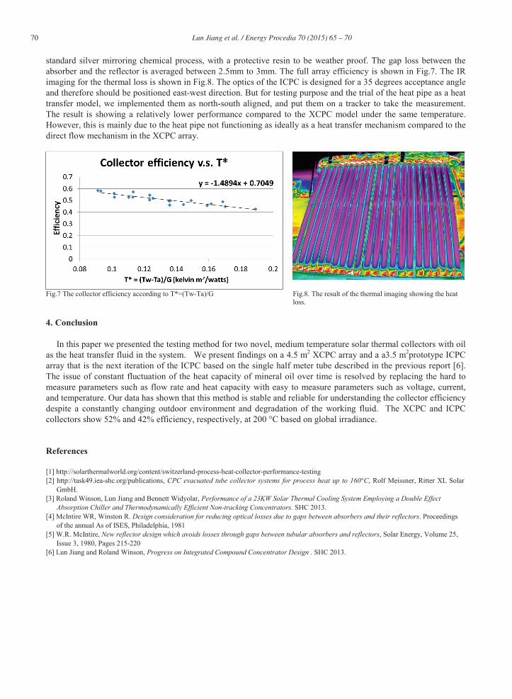
standard silver mirroring chemical process, with a protective resin to be weather proof. The gap loss between the absorber and the reflector is averaged between 2.5mm to 3mm. The full array efficiency is shown in Fig.7. The IR imaging for the thermal loss is shown in Fig.8. The optics of the ICPC is designed for a 35 degrees acceptance angle and therefore should be positioned east-west direction. But for testing purpose and the trial of the heat pipe as a heat transfer model, we implemented them as north-south aligned, and put them on a tracker to take the measurement. The result is showing a relatively lower performance compared to the XCPC model under the same temperature. However, this is mainly due to the heat pipe not functioning as ideally as a heat transfer mechanism compared to the direct flow mechanism in the XCPC array.
Fig.7 The collector efficiency according to T*=(Tw-Ta)/G Fig.8. The result of the thermal imaging showing the heat loss.
4. Conclusion
In this paper we presented the testing method for two novel, medium temperature solar thermal collectors with oil as the heat transfer fluid in the system. We present findings on a 4.5 m2 XCPC array and a a3.5 m2prototype ICPC array that is the next iteration of the ICPC based on the single half meter tube described in the previous report [6]. The issue of constant fluctuation of the heat capacity of mineral oil over time is resolved by replacing the hard to measure parameters such as flow rate and heat capacity with easy to measure parameters such as voltage, current, and temperature. Our data has shown that this method is stable and reliable for understanding the collector efficiency despite a constantly changing outdoor environment and degradation of the working fluid. The XCPC and ICPC collectors show 52% and 42% efficiency, respectively, at 200 °C based on global irradiance.
References
[1] http://solarthermalworld.org/content/switzerland-process-heat-collector-performance-testing [2] http://task49.iea-shc.org/publications, CPC evacuated tube collector systems for process heat up to 160°C, Rolf Meissner, Ritter XL Solar
GmbH. [3] Roland Winson, Lun Jiang and Bennett Widyolar, Performance of a 23KW Solar Thermal Cooling System Employing a Double Effect
Absorption Chiller and Thermodynamically Efficient Non-tracking Concentrators. SHC 2013. [4] McIntire WR, Winston R. Design consideration for reducing optical losses due to gaps between absorbers and their reflectors. Proceedings
of the annual As of ISES, Philadelphia, 1981 [5] W.R. McIntire, New reflector design which avoids losses through gaps between tubular absorbers and reflectors, Solar Energy, Volume 25,
Issue 3, 1980, Pages 215-220 [6] Lun Jiang and Roland Winson, Progress on Integrated Compound Concentrator Design . SHC 2013.