characterization of high temperature solar thermal ...€¦ · the thermal emittance significantly...
TRANSCRIPT

Available online at www.sciencedirect.com
Energy Procedia 00 (2013) 000–000
www.elsevier.com/locate/procedia
1876-6102 © 2013 The Authors. Published by Elsevier Ltd.
Selection and peer review by the scientific conference committee of SolarPACES 2013 under responsibility of PSE AG.
SolarPACES 2013
Characterization of high temperature solar thermal selective
absorber coatings at operation temperature
L. Bartelmeßa*, C. Monte
b, A. Adibekyan
b, O. Sohr
a, C. Ottermann
c, T. Korb
c,
J. Hollandtb
aSCHOTT Solar CSP GmbH, Erich-Schott-Straße 14, D-95666 Mitterteich, Germany bPhysikalisch-Technische Bundesanstalt, Abbestraße 2-12, D-10587 Berlin, Germany
cSCHOTT AG, Hattenbergstraße 10, D-55122 Mainz, Germany
Abstract
In cooperation between the Physikalisch-Technische Bundesanstalt (PTB) and the SCHOTT Solar CSP GmbH (SCHOTT Solar)
measurements have been carried out with the goal to assure, that the directional-hemispherical reflectance measurements, done as
production control by SCHOTT Solar, lead to applicable results for calculating the emittance of absorber tubes for parabolic
trough receivers at their operation temperatures above 350 °C.
A significant influence of the temperature on the directional spectral emittance could not be found. Due to the spectral
characteristics of the emittance with a rising spectral emittance towards shorter wavelength the spectral integrated quantity:
directional total emittance becomes larger with an increasing temperature due to the shift of the Planckcurve.
Furthermore, the measurements of PTB confirmed the emittance values calculated from the reflection measurements and the
directional-hemispherical reflectance measurements performed by SCHOTT.
© 2013 The Authors. Published by Elsevier Ltd.
Selection and peer review by the scientific conference committee of SolarPACES 2013 under responsibility of PSE AG.
Keywords: emittance; measurement methods; calibration; solar selective absorber;
* Corresponding author. Tel.: +49-9633-80-449; fax: +49-3641-28889-378.
E-mail address: [email protected]
L. Bartelmeß/ Energy Procedia 00 (2013) 000–000
1. Introduction
Solar thermal selective absorber coatings are currently characterized by their solar absorptance and their thermal
emittance. The thermal emittance significantly influences the heat loss of the heat collecting elements in a solar
power plant and so the efficiency of the plant. The consideration of the emittance is especially important at high
temperatures above 350 °C occurring in parabolic trough power plants because the heat loss increases
disproportionally with an increasing surface temperature of the heat collecting elements .
At SCHOTT the values for solar absorptance and thermal emittance are currently derived from reflectance
measurements at room temperature in the spectral range from 0.3 μm to 25 μm. The assumed temperature
independence of the emittance had to be confirmed in order to ensure that the measurements at room temperature are
also valid for higher temperatures.
Nomenclature
ε emittance
εds directional spectral emittance
εdt directional total emittance
εBB1 directional spectral effective emittance of the blackbody
ρds directional spectral reflectance
ρx reflectance of the sample
ρr1 reflectance of the first reference sample
ρr2 reflectance of the second reference sample
Fc calibration function
LΩλ directional spectral radiance
LBackground spectral radiance of the thermal background of the RBCF
LBB, Ωλ directional spectral radiance of a blackbody
LBB1 directional spectral radiance of first reference blackbody
measured signal of directional spectral radiance of first reference blackbody
measured signal of directional spectral radiance of blackbody at temperature of liquid nitrogen (second
reference blackbody)
LDetector spectral radiance of the detector
LPlanck spectral blackbody radiance given by Planck’s law
measured signal of radiance emitted from sample
Q Quotient
D Radiation flux on the detector
I Radiation flux on the sample
s detected signal
sx detected signal from the sample
sr1 detected signal from the first reference sample
sr2 detected signal from the second reference sample
T temperature
Tx temperature of sample
TBB1 temperature of first reference blackbody
TBB-LN2 temperature of blackbody at temperature of liquid nitrogen (second reference blackbody)
L. Bartelmeß / Energy Procedia 00 (2013) 000–000
2. Determination of the directional total emittance
The directional total emittance can be determined by detecting the radiation of a heated sample or by measuring
the reflectance of a cold sample and calculating the emittance by applying Kirchhoff’s law.
Detecting the radiation of a heated sample leads to results closer to ‘real life conditions’ as the sample is exposed
to the same physical environment and operating conditions, e.g. the high temperature.
Measuring the reflectance at room temperature is a faster method because the rather long time for heating up the
sample to a stable high temperature is not necessary. However, a prerequisite for the latter method is the assumed
temperature independence of the reflectance which has to be confirmed.
2.1. Measuring the directional spectral emittance by detecting the radiation of a heated sample
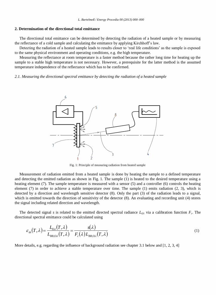
Fig. 1: Principle of measuring radiation from heated sample
Measurement of radiation emitted from a heated sample is done by heating the sample to a defined temperature
and detecting the emitted radiation as shown in Fig. 1. The sample (1) is heated to the desired temperature using a
heating element (7). The sample temperature is measured with a sensor (5) and a controller (6) controls the heating
element (7) in order to achieve a stable temperature over time. The sample (1) emits radiation (2, 3), which is
detected by a direction and wavelength sensitive detector (8). Only the part (3) of the radiation leads to a signal,
which is emitted towards the direction of sensitivity of the detector (8). An evaluating and recording unit (4) stores
the signal including related direction and wavelength.
The detected signal s is related to the emitted directed spectral radiance LΩλ via a calibration function Fc. The
directional spectral emittance could be calculated using
,,
,,
,, TLF
s
TL
TLT
BBcBB
ds
(1)
More details, e.g. regarding the influence of background radiation see chapter 3.1 below and [1, 2, 3, 4]

L. Bartelmeß/ Energy Procedia 00 (2013) 000–000
2.2. Measuring the directional spectral reflectance
As shown in Fig. 2 incident light (9) from a radiation source (10) hits the sample (1) and is reflected to a
detector (8). To achieve spectral data, either the light source (10) could be a tunable monochromatic source or the
detector (8) could be able to disperse the detected light and supply spectrally resolved data to the evaluating and
recording unit (4).
The directional spectral reflectance is given by
I
Dds
(2)
Fig. 2: Principle of reflectance measurement with direct irradiation and direct detection
In order to avoid the necessity of absolutely calibrated light sources and detectors, reference samples are used
commonly. Using two well-known reference samples ρ can be calculated without knowledge of absolute values,
with the preconditions that the lamp power is stable and the detector is linear. The sample reflectance can be
calculated from the signals recorded with the reference samples and the known reflectance of the reference samples:
12
1121
rr
rxrrrx
ss
ss
(3)
For non-transparent materials, such as the solar selective absorber coating and, furthermore, neglecting the
diffusely reflected components Kirchhoff’s law applies approximately:
dsds 1 (4)
By this method the directional spectral emittance can be calculated approximately from directional reflectance
measurements using equations (3) and (4).
L. Bartelmeß / Energy Procedia 00 (2013) 000–000
2.3. Measuring the spectral reflectance with hemispherical irradiation
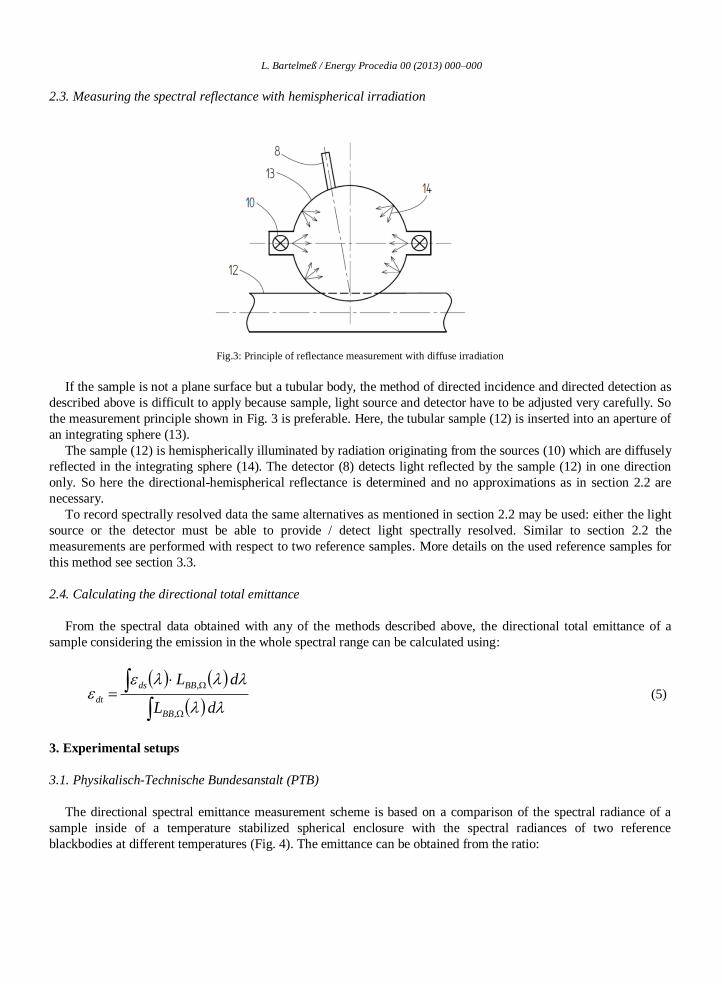
Fig.3: Principle of reflectance measurement with diffuse irradiation
If the sample is not a plane surface but a tubular body, the method of directed incidence and directed detection as
described above is difficult to apply because sample, light source and detector have to be adjusted very carefully. So
the measurement principle shown in Fig. 3 is preferable. Here, the tubular sample (12) is inserted into an aperture of
an integrating sphere (13).
The sample (12) is hemispherically illuminated by radiation originating from the sources (10) which are diffusely
reflected in the integrating sphere (14). The detector (8) detects light reflected by the sample (12) in one direction
only. So here the directional-hemispherical reflectance is determined and no approximations as in section 2.2 are
necessary.
To record spectrally resolved data the same alternatives as mentioned in section 2.2 may be used: either the light
source or the detector must be able to provide / detect light spectrally resolved. Similar to section 2.2 the
measurements are performed with respect to two reference samples. More details on the used reference samples for
this method see section 3.3.
2.4. Calculating the directional total emittance
From the spectral data obtained with any of the methods described above, the directional total emittance of a
sample considering the emission in the whole spectral range can be calculated using:
dL
dL
BB
BBds
dt
,
, (5)
3. Experimental setups
3.1. Physikalisch-Technische Bundesanstalt (PTB)
The directional spectral emittance measurement scheme is based on a comparison of the spectral radiance of a
sample inside of a temperature stabilized spherical enclosure with the spectral radiances of two reference
blackbodies at different temperatures (Fig. 4). The emittance can be obtained from the ratio:

L. Bartelmeß/ Energy Procedia 00 (2013) 000–000
22
22
~)(
~
~)(
~
11 LNBBLNBBBBBB
LNBBLNBBxx
TLTL
TLTLQ
(6)
The first reference blackbody used is either the vacuum low-temperature blackbody (VLTBB) [5] or the vacuum
medium-temperature blackbody (VMTBB) [6] depending on the temperature range. This reference blackbody is
usually operated at a temperature close to the radiation temperature of the sample. The measured signal 11
~BBBB TL
of this blackbody is given by:
DetectorBackgroundBBBBcBBBB LLTLFTL 1111
~ (7)
Fig. 4: Reduced Background Calibration Facility (RBCF)
The spectral radiance of the blackbody is given by LBB1(TBB1)=εBB1 LPlanck(TBB1), where LPlanck(TBB1) is the spectral
blackbody radiance at the respective temperature given by Planck’s law and εBB1 is the directional spectral effective
emittance of the blackbody. LBackground denotes the spectral radiance of the thermal background of the RBCF and
LDetector the spectral radiance of the detector. The value Fc is the spectral responsivity of the spectrometer. The
second reference source, the LN2-cooled blackbody, is mounted on top of the opto-mechanical unit (see Fig. 4) and
is used for the elimination of the background radiation.
Fig. 4 shows a transparent view of the Reduced Background Calibration Facility (RBCF) with the two vacuum
blackbodies VLTBB and VMTBB, the sample holder for emittance measurements, the LN2-cooled reference
blackbody, the Fourier-transform spectrometer and the optical path of the radiation in the LN2-cooled beamline.
3.2. SCHOTT AG, R&D department
The measurements of the directional spectral reflectance at the R&D department of SCHOTT AG were
performed using a commercially available Fourier-transform infrared spectrometer type Nexus. The instrument
operates in the spectral range from 1.4 µm to 25 µm.
Measurements were made in a nitrogen atmosphere at room temperature. The instrument is calibrated using
commercially available certified reflectance standards.

L. Bartelmeß / Energy Procedia 00 (2013) 000–000
3.3. SCHOTT Solar
Fig. 5: Principle of the measurement device for reflectance of tubular samples, right picture: cross sectional view
The measuring device of SCHOTT Solar comprises two integrating spheres (15, 16), each of them equipped with
light sources (10) and light detectors (17, 18, 19, 20, 21) as shown in Fig. 5. The tubular shaped sample (12) is
inserted in special shaped apertures at the lower sides of the spheres (15, 16). It is in close contact with the rim of
the aperture, so no ambient light can enter the sphere.
The light sources (10) are located in a recessed position in the side walls of the spheres, to avoid a direct
illumination of the sample or the detectors and to illuminate the inner surface of the sphere only, which reflects the
light in a diffuse way. The light reflected by the sample towards the sensors is detected as a measuring signal
proportional to the directional-hemispherical reflectance of the sample.
Light sources, inner surface and detectors of sphere 1 (15) are optimized to detect the sample reflectance in the
ultraviolet, visible and near infrared spectral range from 0.3 µm to 2.2 µm, whereas the sphere 2 (16) is optimized to
detect the reflectance in the infrared spectral range from 4 µm to 14 µm.
In the spectral range from 0.3 µm to 2.2 µm the signals are detected with two spectrometers (17, 18) with spectral
resolutions from 0.001 µm in the ultraviolet spectral range to 0.005 µm in the near infrared spectral range. For the
infrared spectral range sphere 2 (16) contains three sensors (19, 20, 21), sensitive at 3.9 µm, 5.1 µm and in the range
from 8 to 14 µm.
During the measurement procedure reference samples are used as explained in section 2.3. For the spectral range
from 0.3 µm to 2.2 µm semi-cylindrical shaped reference samples made of glass are used. Their reflectance values
are calculated from their refractive indices, where the refractive indices have been determined at the certified lab of
SCHOTT AG, Optics Department.
The reference samples for the spectral range from 4 µm to 14 µm are stainless steel tubes ground to the same
roughness as used for the absorber tubes. Instead of applying an absorber coating they are coated with pure materials
whose reflectance data are available from optical handbooks and databases.
To calculate the total emittance, the parameters of an empiric formula are fitted to the measured reflectance
values.
4. Samples
The different measuring setups at the PTB, SCHOTT AG and SCHOTT Solar require different sample types.
Common to all sample types is the coating by SCHOTT Solar. The sample substrates for PTB were small metal
plates, the sample substrates for SCHOTT AG were small glass plates and the sample substrates for SCHOTT Solar
were the metal absorber tubes for the receivers.

L. Bartelmeß/ Energy Procedia 00 (2013) 000–000
Table 1: Samples
Sample
short name
Sample Type Coating Measured by
FM Flat metal Coating Type 1
SCHOTT Solar, Production site 2
PTB
FG1 Flat glass Coating Type 1
SCHOTT Solar, Production site 1
Schott AG
R&D Department
FG2 Flat glass Coating Type 1
SCHOTT Solar, Production site 2
Schott AG
R&D Department
TM1 Tubular metal Coating Type 1
SCHOTT Solar, Production site 2
SCHOTT Solar
Production site 2
TM2 Tubular metal Coating Type 2 SCHOTT Solar
Production site 2
5. Results
5.1. Emittance evaluation according to PTB measurement
Fig. 7 shows the temperature dependence of the directional total emittance of all five samples. The results of PTB
(labeled ‘FM’, green line) are based on actual measurements of the directional spectral emittance of the PTB
samples at different sample temperatures. The directional spectral measurements have been performed under an
angle of 10° and have been integrated over a spectral range from 3 µm to 25 µm.
Fig. 7: Directional total emittance, comparison of all measurements, evaluation for a limited spectral range
The other four results were calculated from reflectance measurements by SCHOTT. To compare the results, the
evaluation of the directional total emittance from reflectance measurements has been done for the same wavelength

L. Bartelmeß / Energy Procedia 00 (2013) 000–000
range as the PTB measurements. This wavelength range is different to SCHOTT’s standard procedure for the
determination of εdt in the production process. Hence the results are not directly comparable with SCHOTT’s
published values for εdt at 400 °C.
Caused by the determination method, the uncertainty of the FM sample increases to lower temperatures, which is
due to the poorer signal-to-noise ratio at lower temperatures.
The FG and TM samples were measured at room temperature only. The emittance at higher temperatures is
calculated, not taking into account that the reflectance of the samples might change with temperature.
Fig. 8: Differences in determined directional total emittance values, the FM-sample, measured by PTB, is the reference
As shown Fig. 8 the directional total emittance values calculated from the reflectance measurements agree with
the emittance values measured by PTB at high temperatures within a tolerance band of ±0,016.
Taking into account, that the values have been determined from different samples, coated within SCHOTT’s
routine production process (where no special effort had been spent to provide equal samples), employing different
measuring devices, this is a good agreement.
5.2. Calculation of emittance at higher temperatures
The temperature dependency of the directional total emittance for the selective absorber coating is significantly
higher, if spectral data starting with lower wavelengths are considered. This is shown in Figure 9. The emittance
values for the TM1 and TM2 samples are calculated considering reflectance data in the spectral range from 0.3 µm
to 30.0 µm, while the PTB data is derived from measurements from 3.0 µm to 25.0 µm. The results of the FM
sample, based on measurements in the spectral range from 3.0µm to 25.0µm, are displayed comparatively.
The slope of the graphs for the TM samples is significant higher than the slope of the graph for the FM sample.
This is because with higher temperature a higher part of the black body radiation energy is emitted in the spectral
range below 3.0 µm, whereas the spectral emittance of a solar selective absorber coating increases strongly in the
spectral range below 2.0 µm. Spectral data only in the range above 3.0 µm cannot describe this effect.
Also the difference in the emittances between TM1 and TM2 are higher if the spectral range starting from 0.3 µm
is considered. This is caused by the fact that the spectral emittances of coatings type 1(TM1) and type 2 (TM2) are
similar in the spectral range above 3.0 µm, but are different in the spectral range below 3.0 µm.

L. Bartelmeß/ Energy Procedia 00 (2013) 000–000
Fig. 9: Temperature dependence of directional total emittance, calculated for TM1 and TM2 with full spectrum (results of FM with limited
spectrum displayed comparatively)
6. Conclusions
The directional total emittance of a solar thermal selective absorber coating has been determined using three
different methods. The results match within a tolerance band of ±0.016. The direct emittance measurements at high
temperatures performed under vacuum by PTB confirm the calculation results based on reflectance measurements at
room temperature in air and nitrogen performed by SCHOTT AG and SCHOTT Solar.
References
[1] Adibekyan, A.; Monte, C.; Kehrt, M.; Gutschwager, B. & Hollandt, J.,
Emissivity measurement under vacuum from 4 µm to 100 µm and from 40 °C to 500 °C at PTB,
International Journal of Thermophysics, 2013, to be published
[2] Monte, C. & Hollandt, J. The Measurement of Directional Spectral Emissivity
in the Temperature Range from 80 °C to 400 °C at the Physikalisch-Technische Bundesanstalt,
High Temperatures - High Pressures, 39, 151-164, (2010)
[3] Monte, C. & Hollandt, J. The determination of the uncertainties of spectral emissivity measurements in air at the
PTB, Metrologia, 47, S172-S181, (2010)
[4] Del Campo L, Pérez-Sáez RB, Esquisabel X, Fernández I, Tello MJ.
New experimental device for infrared spectral directional emissivity measurements in a controlled environment. Rev. Sci. Instrum. 77, 113111 (2006);
[5] Morozova S.P., et al. International Journal of Thermophysics Vol. 29, 341-351 (2008)
[6] Morozova S.P., et al. International Jounal of Thermophysics Vol. 31, 1809-1820, (2010)