characteristics of a crack propagating along the gradient in functionally gradient materials
TRANSCRIPT

International Journal of Solids and Structures 41 (2004) 2879–2898
www.elsevier.com/locate/ijsolstr
Characteristics of a crack propagating along the gradientin functionally gradient materials
Kwang Ho Lee *
Department of Mechanical Engineering, Sangju National University, 386 Gajang Dong, Sangju City, Kyungbuk 742-711, South Korea
Received 9 December 2003; received in revised form 9 December 2003
Available online 27 February 2004
Abstract
Stress and displacement fields for a crack propagating along gradient in a functionally gradient material, which has
(1) a linear variation of shear modulus with a constant density and Poisson�s ratio, and (2) an exponential variation of
shear modulus and density under a constant Poisson�s ratio, are developed.
The equations of motion in nonhomogeneous materials are first developed using displacement potentials and the
solution to the displacement fields and the stress fields for a crack propagating at constant speed though an asymptotic
analysis. The influence of nonhomogeneity on the higher order terms of the stress fields are explicitly brought out.
Using these stress components, isochromatic fringes around the propagating crack are generated for different crack
speeds and nonhomogeneity and the effects of nonhomogeneity on these fringes are discussed.
� 2004 Elsevier Ltd. All rights reserved.
Keywords: Functionally gradient materials; FGM constant; Propagating crack; Stress and displacement fields; Stress intensity factors
1. Introduction
Several novel materials have recently been developed to meet the increasing demand of modern tech-
nology (Niino et al., 1987; Butcher et al., 1999; Jedamzik et al., 2000; Zeng et al., 2000). Among these,functionally graded materials (FGMs) are unique in that they offer the possibility of tailoring their con-
stituents and gradation to match the end use. These materials also have certain advantages over existing
isotropic materials and conventional composites, especially in applications that demand, resistance to
corrosion and high temperature as in furnace walls and turbine blades, wear resistance as in gears and high
speed machine tools, combined with good toughness and strength characteristics. Conventional materials,
which satisfy all these requirements, are rare. The general practice therefore has been to provide an interior
wall made of high heat resistance material in the case of furnaces and in the case of gears and tools with
super wear resistance material. Unfortunately, such interior walls or coatings are mechanically weak at theinterface due to discontinuous stresses resulting from thermal gradients and due to poor bond strength,
* Tel.: +82-54-530-5404; fax: +82-54-530-5407.
E-mail address: [email protected] (K.H. Lee).
0020-7683/$ - see front matter � 2004 Elsevier Ltd. All rights reserved.
doi:10.1016/j.ijsolstr.2004.01.004

2880 K.H. Lee / International Journal of Solids and Structures 41 (2004) 2879–2898
leading to interface cracking and spallation. FGMs can be effectively designed to overcome these defi-
ciencies, by proper choice of the constituents and gradation. The spatial variation of the material com-
position in FGMs results in a medium with varying elastic and physical properties and calls for special
methods of processing and analysis.Until now, the fracture of an FGM under quasi-static loading, which is one of the predominant modes of
material failure, has been investigated extensively (Erdogan, 1995; Jin and Batra, 1996; Gu et al., 1999). The
primary conclusion of these investigations is that the classical inverse square root singular nature of the
stress field is preserved in FGMs, however, the stress intensity factor is influenced by the nonhomogeneity
of the material. Therefore, very close to the crack tip in FGMs, the stresses are identical to that in a
homogeneous material. The structure of the stress field away from crack tip is significantly altered by
nonhomogeneity, as has been demonstrated by Eischen (1987) and Parameswaran and Shukla (2002).
The behavior of propagating cracks in FGMs has also attracted some attention. Following an earlierstudy by Atkinson and List (1978), several groups have investigated the behavior of propagating cracks in
FGMs especially after their introduction. (Wang and Meguid, 1995; Rousseau and Tippur, 2001; Jiang and
Wang, 2002). For propagating cracks along the gradient in FGMs, Parameswaran and Shukla (1999, 2002)
developed the structure of the first stress invariant and the out of plane displacement bring out the effects
of nonhomogeniety. However, nonhomogeneity specific terms for individual stress components have not
been developed. Such stress fields are required in the analysis of full field experimental data obtained
through techniques such as photoelasticity and coherent gradient sensing (CGS). This paper provides the
stress and displacement fields for a crack propagating at a constant speed along the direction of propertyvariation in an FGM. The elastodynamic problem is formulated in terms of displacement potentials and
the solution is obtained through an asymptotic analysis assuming a linear variation of elastic modulus with
a constant density in Section 2. In Section 3, the solution for an identical exponential variation of elastic
properties and density is obtained by employing the same procedure as used in Section 2. In Section 4,
using the stress and displacement fields obtained in Sections 2 and 3, the characteristics of stress and
displacement components around a propagating crack tip are examined for different crack speeds and
nonhomogeneity.
2. Stress and displacement fields for a linear variation of elastic properties with a constant density
2.1. Formation for equilibrium equations
When the FGM has a linearly increasing shear modulus such as l ¼ l0ð1þ 1X Þ under a constant densityq and Poisson�s ratio m, the relationship between stresses and strains can be written as
rX ¼ ½a11eX þ a12eY �ð1þ 1X ÞrY ¼ ½a12eX þ a11eY �ð1þ 1X ÞsXY ¼ l0cXY ð1þ 1X Þ
ð1Þ
where X is the reference coordinate, rij the inplane stress components, a11 ¼ k0 þ 2l0 and a12 ¼ k0, and k0and l0 denoting Lame�s constant and the shear modulus at X ¼ 0, respectively. 1 is the nonhomogeneity
constant which has dimension (length)�1. It should be noted in this case that the longitudinal and shear
wave speeds of the medium are variable.
If the deformation is plane strain, the displacements u and v which are derived from dilatational and
shear wave potentials U and W can be expressed by Eq. (2)
u ¼ oUoX
þ oWoY
; v ¼ oUoY
� oWoX
ð2Þ

K.H. Lee / International Journal of Solids and Structures 41 (2004) 2879–2898 2881
The equilibrium in dynamic state is given by Eq. (3)
orX
oXþ osXY
oY¼ q
o2uot2
;osXYoX
þ orY
oY¼ q
o2vot2
ð3Þ
Substituting Eq. (2) into Eq. (1), and substituting Eq. (1) into Eq. (3), the equations for the dynamic state
can be obtained as
o
oXð1
�þ 1X Þðk þ 2Þr2U� q
l0
o2Uot2
�þ o
oYð1
�þ 1X Þr2W� q
l0
o2Wot2
�� 21
o2UoY 2
�� o2WoXoY
�¼ 0
ð4aÞ
o
oYð1
�þ 1X Þðk þ 2Þr2U� q
l0
o2Uot2
�� o
oXð1
�þ 1X Þr2W� q
l0
o2Wot2
�þ 21
o2WoY 2
�þ o2UoXoY
�¼ 0
ð4bÞ
where k ¼ k0=l0, Eq. (4) can be satisfied when expressed as Eq. (5)
ð1þ 1X Þðk þ 2Þr2U� ql0
o2Uot2
þ 21oWoY
¼ 0 ð5aÞ
ð1þ 1X Þr2W� ql0
o2Wot2
� 21oUoY
¼ 0 ð5bÞ
For a propagating crack, the transformed crack tip coordinates are x ¼ X � ct, y ¼ Y . From this relation,
we can write the equations of motion for steady state can be written as
a2lo2Uox2
þ o2Uoy2
þ bxo2Uox2
�þ o2U
oy2
�þ 2bk þ 2
oWoy
¼ 0 ð6aÞ
a2so2Wox2
þ o2Woy2
þ bxo2Wox2
�þ o2W
oy2
�� 2b
oUoy
¼ 0 ð6bÞ
where
al ¼
ffiffiffiffiffiffiffiffiffiffiffiffiffiffiffiffiffiffiffiffiffiffiffi1� c
cl
� �2s
; as ¼
ffiffiffiffiffiffiffiffiffiffiffiffiffiffiffiffiffiffiffiffiffiffiffi1� c
cs
� �2s
; cs ¼ffiffiffiffiffilc
q
r
cl ¼ cs
ffiffiffiffiffiffiffiffiffiffiffiffiffiffiffiffiffi2ð1� mÞ1� 2m
rfor plane strain; cl ¼ cs
ffiffiffiffiffiffiffiffiffiffiffi2
1� m
rfor plane stress;
lc ¼ l0ð1þ a1Þ; bða; 1Þ ¼ 1l0
lc
¼ 11þ a1
The a is half the crack length in a center crack or the crack length of an edge crack. lc and l0 are shear
modulus at the crack tip and x ¼ �a, respectively. c, cl and cs are the crack propagation velocity, elastic
dilatational wave velocity and elastic shear wave velocity at the crack tip. In this case, bða; 1Þ is dependenton the crack length and the nonhomogeneity constant 1. It is very difficult to obtain analytical solutions for
the elastodynamic differential equation (6). Thus, an asymptotic analysis similar to that employed byFreund (1990) is used to expand the stress field around the propagating crack. To obtain an asymptotic
expansion of the fields around the crack tip, the crack tip coordinates are scaled to fill the entire field of

2882 K.H. Lee / International Journal of Solids and Structures 41 (2004) 2879–2898
observation (Freund, 1990). This can be achieved by introducing new coordinates g1 ¼ x=e, g2 ¼ y=e and eis a small arbitrary positive number. For very small values of e, the points very close to the crack tip
are mapped into the range of observation in the g1; g2 plane. In the scale coordinates, Eq. (6) takes the form
a2lo2Uog21
þ o2Uog22
þ eb g1o2Uog21
��þ o2U
og22
�þ 2
k þ 2
oWog2
�¼ 0 ð7aÞ
a2so2Wog21
þ o2Wog22
þ eb g1o2Wog21
��þ o2W
og22
�� 2
oUog2
�¼ 0 ð7bÞ
At this stage it is assumed that U and W can be expanded by powers of e as
Uðx; yÞ ¼ Uðeg1; eg2Þ ¼X1n¼1
en=2þ1Unðg1; g2Þ
Wðx; yÞ ¼ Wðeg1; eg2Þ ¼X1n¼1
en=2þ1Wnðg1; g2Þð8Þ
as r ¼ffiffiffiffiffiffiffiffiffiffiffiffiffiffix2 þ y2
p! 0 and e is a small arbitrary value. Substituting Eq. (8) into Eq. (7) and setting the partial
differential equations associated with each power of e to zero, the coupled differential equations for Un and
Wn can be obtained.
a2lo2Un
og21þ o2Un
og22¼ �bg1
o2Un�2
og21
�þ o2Un�2
og22
�� 2bk þ 2
oWn�2
og2ð9aÞ
a2so2Wn
og21þ o2Wn
og22¼ �bg1
o2Wn�2
og21
�þ o2Wn�2
og22
�þ 2b
oUn�2
og2ð9bÞ
The Un and Wn have the complex functions zlðg1; ialg2Þ and zsðg1; iasg2Þ, respectively, and Un ¼ Wn ¼ 0 if
n < 0. When the 1 ¼ 0, the right side terms of equation become zero.
2.2. The stress and displacement fields for n ¼ 1; 2
From Eq. (9), the differential equations for n ¼ 1 and 2 are given in Eq. (10)
a2lo2Un
og21þ o2Un
og22¼ 0; a2s
o2Wn
og21þ o2Wn
og22¼ 0 ð10Þ
Eq. (10) is the Laplace equation and the same as that for a homogeneous material. The general solutions of
Eq. (10) for fields Un and Wn can be assumed as
Unðg1; g2Þ ¼ �Re
Z/nðzlÞdzl
Wnðg1; g2Þ ¼ �Im
ZwnðzsÞdzs
ð11Þ
Substituting the differentiation of Un and Wn in Eq. (11) into Eq. (2), the displacements in scaled plane can
be obtained as en=2f/nðg1; g2Þ;wnðg1g2Þg. Thus, the displacements u and v in the unscaled physical plane forn ¼ 1 and 2 can be expressed as Eq. (12).
u ¼ �Ref/nðzlÞ þ aswnðzsÞgv ¼ Imfal/nðzlÞ þ wnðzsÞg
ð12Þ

K.H. Lee / International Journal of Solids and Structures 41 (2004) 2879–2898 2883
Substituting the differentiation of Eq. (12) into Eq. (1), the stress fields in the scaled plane can be obtained
as en=2�1lf/nðg1; g2Þ;wnðg1g2Þg. Thus the stress rij in the unscaled physical plane for n ¼ 1 and 2 can be
expressed as Eq. (13).
rx ¼ �lRefð1þ 2a2l � a2s Þ/0nðzlÞ þ 2asw
0nðzsÞg
ry ¼ lRefð1þ a2s Þ/0nðzlÞ þ 2asw
0nðzsÞg
sxy ¼ lImf2al/0nðzlÞ þ ð1þ a2s Þw
0nðzsÞg
ð13Þ
The /nðzlÞ and wnðzlÞ can be written with a power series as
/nðzlÞ ¼X2
n¼1
Anzn=2l ; wnðzsÞ ¼
X2
n¼1
Bnzn=2s ð14Þ
where An and Bn are complex constants and zl ¼ xþ ialy and zs ¼ xþ iasy. Substituting Eq. (14) into Eq.(13), applying traction free boundary conditions on the crack surface to Eq. (13), the stresses for propa-
gating crack in unscaled physical plane can be obtained as Eq. (15).
rxn ¼ ð1þ bxÞX2
n¼1
r0xn; ryn ¼ ð1þ bxÞ
X2
n¼1
r0yn; sxyn ¼ ð1þ bxÞ
X2
n¼1
s0xyn ð15Þ
where
r0xn ¼
K0nBIðcÞffiffiffiffiffiffi2p
p n ð1�
þ 2a2l � a2s Þrn�22
l cosn� 2
2
� �hl � 2ashðnÞr
n�22
s cosn� 2
2
� �hs
�
þ K�nBIIðcÞffiffiffiffiffiffi2p
p n ð1�
þ 2a2l � a2s Þrn�22
l sinn� 2
2
� �hl � 2ashð�nÞr
n�22
s sinn� 2
2
� �hs
�
r0yn ¼
K0nBIðcÞffiffiffiffiffiffi2p
p n�� ð1þ a2s Þr
n�22
l cosn� 2
2
� �hl þ 2ashðnÞr
n�22
s cosn� 2
2
� �hs
�
þ K�nBIIðcÞffiffiffiffiffiffi2p
p n�� ð1þ a2s Þr
n�22
l sinn� 2
2
� �hl þ 2ashð�nÞr
n�22
s sinn� 2
2
� �hs
�
s0xyn ¼K0
nBIðcÞffiffiffiffiffiffi2p
p n�� 2alr
n�22
l sinn� 2
2
� �hl þ ð1þ a2s ÞhðnÞr
n�22
s sinn� 2
2
� �hs
�
þ K�nBIIðcÞffiffiffiffiffiffi2p
p n 2alrn�22
l cosn� 2
2
� �hl
�� ð1þ a2s Þhð�nÞr
n�22
s cosn� 2
2
� �hs
�
The displacement for propagating crack in an unscaled physical plane can be obtained as Eq. (16).
un ¼1
ð1þ faÞX2
n¼1
u0n; vn ¼1
ð1þ faÞX2
n¼1
v0n ð16Þ
where
u0n ¼K0
nBIðcÞl0
ffiffiffi2
p
rrn2
l cosn2
� hl
n� ashðnÞr
n2s cos
n2
� hsoþK�
nBIIðcÞl0
ffiffiffi2
p
rrn2
l sinn2
� hl
n� ashð�nÞr
n2s sin
n2
� hso

2884 K.H. Lee / International Journal of Solids and Structures 41 (2004) 2879–2898
v0n ¼K0
nBIðcÞl0
ffiffiffi2
p
r n� alr
n2
l sinn2
� hl þ hðnÞr
n2s sin
n2
� hsoþK�
nBIIðcÞl0
ffiffiffi2
p
ralr
n2
l cosn2
� hl
n� hð�nÞr
n2s cos
n2
� hso
rj ¼ffiffiffiffiffiffiffiffiffiffiffiffiffiffiffiffiffiffiffiffiffiffix2 þ ðajyÞ2
q; hj ¼ tan�1ðajy=xÞ; j ¼ l; s
hðnÞ ¼ 2al1þ a2s
ðn ¼ oddÞ; 1þ a2s2as
ðn ¼ evenÞ; �n ¼ nþ 1
BIðcÞ ¼1þ a2s
4alas � ð1þ a2s Þ2; BIIðcÞ ¼
2as4alas � ð1þ a2s Þ
2
K0I and K0
II for n ¼ 1 are the stress intensity factors KI and KII, respectively. When n ¼ 1 and 2, the dif-
ferential equations in Eq. (10) are the same as those for a homogeneous material (Freund, 1990) but their
stress and displacement fields are influenced by the nonhomogeneity constant 1.
2.3. Stress and displacement fields for n ¼ 3
For nP 3 in Eq. (9), the Un and Wn become nonhomogeneous fields, and only n ¼ 3 is considered to
generate the fields in this study. To solve Eq. (9), the relation between U1ðzlÞ and W1ðzsÞ must be known. If
the relation between U1ðzlÞ and W1ðzsÞ does not apply to Eq. (9), the dilatational and rotational terms in the
equations of motion remain coupled. This causes the stress fields to be infinite when the crack velocity
approaches zero. Considering Eq. (10), the relation between U1ðzlÞ and W1ðzsÞ can be obtained when the 1terms in Eq. (4) are zero. Thus, the relations can be expressed as (see Appendix A).
o
og2W1ðzsÞ ¼ � AðalÞ
BðasÞo
og1U1ðzlÞ ¼ �ðk þ 2Þ o
og1U1ðzlÞ ð17aÞ
1
k þ 2
o
og1W1ðzsÞ ¼
o
og2U1ðzlÞ ð17bÞ
where
AðalÞ ¼ ðk þ 2Þ ð1�
� a2l Þ �qc2
l0ðk þ 2Þ
�; BðasÞ ¼ ð1� a2s Þ �
qc2
l0
Substituting Eq. (17) into Eq. (9), Eq. (9) becomes as
a2lo2U3
og21þ o2U3
og22¼ �bg1
o2U1
og21
�þ o2U1
og22
�þ 2b
oU1
og1ð18aÞ
a2so2W3
og21þ o2W3
og22¼ �bg1
o2W1
og21
�þ o2W1
og22
�þ 2bk þ 2
oW1
og1ð18bÞ
Let the right side terms U1ðzlÞ and W1ðzsÞ in Eq. (18) put �ReRU1ðzlÞdzl, �Im
RW1ðzsÞdzs, respectively,
then the solutions for U3ðzlÞ and W3ðzsÞ can be obtained as

K.H. Lee / International Journal of Solids and Structures 41 (2004) 2879–2898 2885
U3ðg1; g2Þ ¼ Re
��Z
/3ðzlÞdzl þ b1� a2la2l
g1r2l aj/
01ðzlÞ
�� 1
3a2lr2l /1ðzlÞ
��ð19aÞ
W3ðg1; g2Þ ¼ Im
��Z
w3ðzsÞdzs þ b1� a2sa2s
g1r2sajw
01ðzsÞ
�� 1
3ðk þ 2Þa2sr2sw1ðzsÞ
��ð19bÞ
where aj is a coefficient of trigonometric function, and
aj ¼14: aj cos 3
2hj; aj sin 3
2hj
�16: aj cos 1
2hj; aj sin 1
2h
��
The first term on the right hand side in Eq. (19) corresponds to that for a homogeneous material and the
additional term is the result of the nonhomogeneity of the material. The nonhomogeneous K displacement
field obtained from Eq. (19), unonðb;KÞ can be applied in r ! 0. However the displacement components
obtained from the last terms in Eq. (19) approach very large values except when r ¼ 0 when the crack
propagation velocity approaches zero. Such a behavior is not consistent with the physical meaning of r > 0.
Thus, the last terms can not be applied in the case where r > 0. Substituting Eq. (19) into Eq. (2) andapplying the traction free boundary condition to the crack surface, the components of displacement in the
unscaled plane can be expressed as
u3 ¼1
ð1þ faÞ u03
(� b
KIBIðcÞl0
ffiffiffiffiffiffi2p
p r3=2l
ð1� a2l Þa2l
F ðhlÞ�
þ r3=2s h1ð1� a2s Þ
asGðhsÞ
�
� bKIIBIIðcÞl0
ffiffiffiffiffiffi2p
p r3=2l
ð1� a2l Þa2l
HðhlÞ�
þ r3=2s�h1
ð1� a2s Þas
IðhsÞ�)
ð20Þ
v3 ¼1
ð1þ faÞ v03
(� b
KIBIðcÞl0
ffiffiffiffiffiffi2p
p r3=2l
ð1� a2l Þal
IðhlÞ�
þ r3=2s h1ð1� a2s Þ
a2sHðhsÞ
�
þ bKIIBIIðcÞl0
ffiffiffiffiffiffi2p
p r3=2l
ð1� a2l Þal
GðhlÞ�
þ r3=2s�h1
ð1� a2s Þa2s
F ðhsÞ�)
ð21Þ
where
F ðhjÞ ¼1
16cos
5
2hj þ
1
12cos
3hj2
þ 3
8cos
hj2; GðhjÞ ¼ � 1
16cos
5
2hj þ
1
12cos
3hj2
þ 1
8cos
hj2
HðhjÞ ¼ � 1
16sin
5
2hj þ
1
12sin
3hj2
� 3
8sin
hj2
IðhjÞ ¼1
16sin
5
2hj þ
1
12sin
3hj2
� 1
8sin
hj2; j ¼ l; s
Substituting the differentiations of Eqs. (20) and (21) into Eq. (1), the stresses for a propagating crack in theunscaled plane can be obtained as

2886 K.H. Lee / International Journal of Solids and Structures 41 (2004) 2879–2898
rx3 ¼ ð1þ bxÞ r0x3
�þ b
KIBIðcÞffiffiffiffiffiffi2p
p r1=2l ð1�
þ 2a2l � a2s ÞA1C1ðhlÞ �ð1� a2s Þð1� a2l Þ
A1
2C2ðhlÞ
�
þ bKIBIðcÞffiffiffiffiffiffi
2pp r1=2s
�� 2asB1h1
1
4cos
1
2hs
�� 1
16cos
3hs2
þ 1
32cos
7
2hs
��
þ bKIIBIIðcÞffiffiffiffiffiffi
2pp r1=2l
�� ð1þ 2a2l � a2s ÞA1S1ðhlÞ þ
ð1� a2s Þð1� a2l Þ
A1
2S2ðhlÞ
�
þ bKIIBIIðcÞffiffiffiffiffiffi
2pp r1=2s 2asB1
�h1
��� 1
4sin
1
2hs �
1
16sin
3hs2
þ 1
32sin
7
2hs
���ð22Þ
ry3 ¼ ð1þ bxÞ r0y3
�þ b
KIBIðcÞffiffiffiffiffiffi2p
p r1=2l
�� ð1þ a2s ÞA1C1ðhlÞ þ
ð1þ a2s � 2a2l Þð1� a2l Þ
A1
2C2ðhlÞ
�
þ bKIBIðcÞffiffiffiffiffiffi
2pp r1=2s 2asB1h1
1
4cos
1
2hs
��� 1
16cos
3hs2
þ 1
32cos
7
2hs
��
þ bKIIBIIðcÞffiffiffiffiffiffi
2pp r1=2l ð1
�þ a2s ÞA1S1ðhlÞ �
ð1þ a2s � 2a2l Þð1� a2l Þ
A1
2S2ðhlÞ
�
þ bKIIBIIðcÞffiffiffiffiffiffi
2pp r1=2s 2asB1
�h11
4sin
1
2hs
��þ 1
16sin
3hs2
� 1
32sin
7
2hs
���ð23Þ
sxy3 ¼ ð1þ bxÞ s0xy3
�þ b
KIBIðcÞffiffiffiffiffiffi2p
p r1=2l
�� 2alA1
1
4sin
1
2hl
�þ 1
16sin
3hl2
� 1
32sin
7
2hl
��
þ bKIBIðcÞffiffiffiffiffiffi
2pp r1=2s h1B1
�� ð1þ a2s ÞS1ðhsÞ þ
1
2S2ðhsÞ
�
þ bKIIBIIðcÞffiffiffiffiffiffi
2pp r1=2l
�� 2alA1
�� 1
4cos
1
2hl þ
1
16cos
3hl2
� 1
32cos
7
2hl
��
þ bKIIBIIðcÞffiffiffiffiffiffi
2pp r1=2s
�h1B1
�� ð1þ a2s ÞC1ðhsÞ þ
1
2C2ðhsÞ
��ð24Þ
where
A1 ¼1� a2la2l
; B1 ¼1� a2sa2s
C1ðhjÞ ¼3
16cos
3
2hj þ
1
32cos
7
2hj; C2ðhjÞ ¼ cos
1
2hj þ cos
3
2hj
S1ðhjÞ ¼3
16sin
3
2hj þ
1
32sin
7
2hj; S2ðhjÞ ¼ sin
3
2hj � sin
1
2hj
h1 ¼ � 14A1al½32� 7ð1þ a2s Þ�B1
; �h1 ¼A1fð1þ a2s Þ½7ð1� a2l Þ � 32� þ 64a2l g
½14asð1� a2l Þ�B1
Finally, the fields for FGM, rij and uj are given in Eq. (25)
rij ¼X3
n¼1
rijn; uj ¼X3
n¼1
ujn ð25Þ

K.H. Lee / International Journal of Solids and Structures 41 (2004) 2879–2898 2887
The stress fields in Eq. (25) satisfy the traction free condition on the crack surface (h ¼ �p). When the
nonhomogeneity parameter 1 ¼ 0, the equations reduce to the fields for an isotropic homogeneous material.
It can be observed from the stress and displacement fields (Eqs. (20)–(24)) that, due to nonhomogeneity, the
higher order terms (n ¼ 3 and above) involve additional expressions containing the stress intensity factor.However, these additional expressions scaled by the nonhomogeneity parameter, b (for example see Eqs.
(20)–(24)) become insignificant compared to the singular term of the expansion at the crack tip. Thus, very
close to the crack tip, the stress and displacement fields can be adequately represented by the solution for
homogeneous materials. However, the stress and displacement field that is remote from the crack tip must
be expressed by Eq. (25) which contains nonhomogeneity specific expressions. Generally, in order to obtain
the fracture parameters for a homogeneous material from experimental data obtained through optical
techniques such as photoelasticity or coherent gradient sensing (CGS) the use of the first few terms of the
stress fields is sufficient. The coefficient of term n ¼ 1ðr�1=2fijÞ is proportional to the stress intensity factorand that of the term n ¼ 2ðr0fijÞ is the uniform stress rox in the direction of the crack. In FGMs, it is
necessary to use at least three terms of the fields to explicitly account for the nonhomogeneity effects when
extracting fracture parameters from experimental data.
3. Stress and displacement fields for an exponential variation of elastic properties and density
The elastic constants l and q of FGM are assumed to vary in an exponential manner as given by Eq.
(26), where as the Poisson�s ratio m is assumed to be constant.
l ¼ l0 expðfX Þ; q ¼ q0 expðfX Þ ð26Þ
l0 and q0 are shear modulus at X ¼ 0, respectively, and 1 is the nonhomogeneity constant. By employingthe same procedure used in Section 2.1, the equilibrium equation for exponential variation of elastic
properties can be obtained as
o
oXðk
�þ 2Þr2U� q0
l0
o2Uot2
�þ o
oYr2W
�� q0
l0
o2Wot2
�þ f kr2U
�þ 2
o2UoX 2
þ 2o2WoXoY
�¼ 0 ð27aÞ
o
oYðk
�þ 2Þr2U� q0
l0
o2Uot2
�� o
oXr2W
�� q0
l0
o2Wot2
�þ f 2
o2UoXoY
�þ o2W
oY2� o2W
oX2
�¼ 0 ð27bÞ
where k ¼ k0=l0. For a propagating crack the transformed crack tip coordinates are x ¼ X � ct, y ¼ Y .Thus, Eq. (27) can be expressed as
a2lo2Uox2
þ o2Uoy2
þ foUox
þ fk þ 2
oWoy
¼ 0 ð28aÞ
a2so2Wox2
þ o2Woy2
þ foWox
þ fkoUoy
¼ 0 ð28bÞ
It should be noted here that, Eq. (28), unlike Eq. (6) for the linear variation of elastic properties, have
coefficients which are all constants. Hence, for crack speeds that are less than the shear wave speed of the
material, the partial differential equation is elliptic over the entire domain. However, the form of the
equation is still different from the classical wave equation. The same procedure used in the previous section
is used to obtain the asymptotic expansion of the displacement and stress fields. For n equal to 1 and 2, thepartial differential equations and their solutions are the same as those in the case of linear variation and
hence, the crack tip stress and displacement fields can be expressed as

2888 K.H. Lee / International Journal of Solids and Structures 41 (2004) 2879–2898
rxn ¼ efxX2
n¼1
r0xn; ryn ¼ efx
X2
n¼1
r0yn; sxyn ¼ efx
X2
n¼1
s0xyn ð29Þ
The displacement for propagating crack in unscaled physical plane can be obtained as Eq. (30).
un ¼ e�1aX2
n¼1
u0n; vn ¼ e�faX2
n¼1
v0n ð30Þ
The form of the partial differential equation for n greater than 2 is somewhat different from Eq. (9) and is
given as
a2lo2Un
og21þ o2Un
og22¼ �f
oUn�2
og1
�þ 1
k þ 2
oWn�2
og2
�ð31aÞ
a2so2Wn
og21þ o2Wn
og22¼ �f
oWn�2
og1
�þ k
oUn�2
og2
�ð31bÞ
Applying the relation between U1ðzlÞ and W1ðzsÞ in Eq. (17) to Eq. (31), Eq. (31) becomes as
a2lo2U3
og21þ o2U3
og22¼ 0 ð32Þ
a2so2W3
og21þ o2W3
og22¼ �f ð1
�� dsÞ
oW1
og1
�ð33Þ
where
ds ¼�kk þ 2
¼ 1þ a2s � 2a2l1� a2s
Let the right side term W1ðzlÞ in Eq. (33) put �ImRw1ðzsÞdzs, then the U3ðzlÞ and W3ðzsÞ can be obtained
as
U3ðg1; g2Þ ¼ Re
��Z
/3ðzlÞdzl�
W3ðg1; g2Þ ¼ Im
��Z
w3ðzsÞdzs þ f1� ds6a2s
r2sw1ðzsÞ� ð34Þ
Substituting Eq. (34) into Eq. (2), the components of displacement in the unscaled plane can be expressed as
u3 ¼ expð�faÞ u03
(� f
KIBIðcÞl0
ffiffiffiffiffiffi2p
p r3=2s
1
ashð1
�� dsÞ
1
3cos
3hs2
�� 1
2cos
hs2
��
� fKIIBIIðcÞl0
ffiffiffiffiffiffi2p
p r3=2s
1
as�hð1
�� dsÞ
1
3sin
3hs2
�þ 1
2sin
hs2
��)ð35Þ
v3 ¼ expð�faÞ v03
(� f
KIBIðcÞl0
ffiffiffiffiffiffi2p
p r3=2s
1
a2shð1
�� dsÞ
1
3sin
3hs2
�� 1
2sin
hs2
��
þ fKIIBIIðcÞl0
ffiffiffiffiffiffi2p
p r3=2s
1
a2s�hð1
�� dsÞ
1
3cos
3hs2
�þ 1
2cos
hs2
��)ð36Þ

K.H. Lee / International Journal of Solids and Structures 41 (2004) 2879–2898 2889
Substituting the differentiations of Eqs. (35) and (36) into Eq. (1), the stresses for a propagating crack in
unscaled plane can be obtained as
rx3 ¼ expðfxÞ r0x3
�þ f
KIBIðcÞffiffiffiffiffiffi2p
p r1=2s asBh2
cos3hs2
� �þ f
KIIBIIðcÞffiffiffiffiffiffi2p
p r1=2s as�B2
�h sin3hs2
� ��ð37Þ
ry3 ¼ expðfxÞ r0y3
�þ f
KIBIðcÞffiffiffiffiffiffi2p
p r1=2s as
�� B
2h cos
3hs2
�þ f
KIIBIIðcÞffiffiffiffiffiffi2p
p r1=2s asB2�h sin
3hs2
� ��ð38Þ
sxy3 ¼ expðfxÞ s0xy3
�þ f
KIBIðcÞffiffiffiffiffiffi2p
p r1=2s Bh��ð1� a2s Þ sin
hs2þ 1þ a2s
4sin
3hs2
�
þ fKIIBIIðcÞffiffiffiffiffiffi
2pp r1=2s B�h ð1
�� a2s Þ cos
hs2þ 1þ a2s
4cos
3hs2
��ð39Þ
where
B ¼ 1� dsa2s
Even if the stresses for n ¼ 3 are expressed as the above equations, considering the traction free con-
ditions on a crack surface (h ¼ �p), h and �h must be zero. Thus, the fields rij and uj for an exponential
variation in elastic properties and density are can be expressed as Eq. (40).
rij ¼ expðfxÞX1n¼1
r0ijn; uj ¼ expð�faÞ
X1n¼1
u0jn ð40Þ
The stress fields around the crack tip (x is small) in Eq. (40) can be expressed as
rij ffi r0ij1 þ r0
ij2ðr0xÞ þ fx½r0ij1 þ r0x� þ � � � ð41Þ
As is known from Eq. (41), higher order terms of stresses at the crack tip in the form of an asymptotic
expansion show the coefficients of r�1=2 and r0 to also be identical to those present in the asymptotic the
behavior of a formulation of homogeneous crack tip. Only terms of the order r1=2 and beyond would beinfluenced by such a gradient, which would have coefficients different from those of homogeneous mate-
rials. However, higher terms of displacements at the crack tip as an asymptotic expansion would be
influenced not by 1x but by 1a.
4. Characteristics of a propagating crack in an FGM
4.1. Effect of nonhomogeneity on stress fields
In order to investigate the effects of nonhomogeneity on stress components close to the crack tip, Eq.
(41) for the exponential variation of elastic properties is used. To analyze the isochromatic fringe patterns
that are remote from the crack tip, Eqs. (25) and (41) are used. In addition, all the coefficients other than
those proportional to the stress intensity factor are assumed to be zero. The stress components (see Fig. 1)
were evaluated as a function of the angular position (h) at three different radial locations (r) for a near
stationary crack and for a crack propagating at M ¼ 0:7, where M is c=cs. The mechanical properties of the
particulate FGM developed by Parameswaran and Shukla (2000), as shown in Table 1, were used. The
variation of the elastic modulus for this FGM is shown in Fig. 2, along with the exponential fit. Figs. 3–5show the angular variation of the normalized stress components for a mode I crack and Figs. 6–8 show the

Fig. 1. Stress components in the vicinity of the crack tip.
Table 1
Mechanical properties for a polyester FGM
Nonhomogeneous shear modulus, lðX Þ lðX Þ ¼ 1:316e1X (GPa)
FGM constant, 1 1 ¼ 1:19=m
Poisson�s ratio, m m ¼ 0:33
Density at X ¼ 0, q0 q0 ¼ 1200 (kg/m3)
0.00 0.05 0.10 0.15 0.20 0.25 0.30 0.350.0
0.4
0.8
1.2
1.6
2.0
2.4
2.8
µ = µo exp (ζX)
: ζ=1.19/m: ζ=-1.19/m: ζ=0
Shea
r mod
ulus
, µ(G
Pa)
X Location from left side of specimen(m)
Fig. 2. Variation of shear modulus l with X location.
2890 K.H. Lee / International Journal of Solids and Structures 41 (2004) 2879–2898
variation for a mode II crack. The normalization is carried out by dividing the stress components by
(K=ffiffiffiffiffiffiffi2pr
p). In a homogeneous material this would imply that only the singular term of the stress field needs
to be considered and due to the normalization scheme the curves for different values of r will fall on top ofeach other in Figs. 3–8. However, in the case of FGMs, the additional expression of the higher order term
(r1=2) proportional to the stress intensity factor arising out of nonhomogeneity are still retained through
which the nonhomogeneity effects are manifested.
Fig. 3 shows the normalized stress rx=rþI around a near stationary crack tip and a propagating crack tip
for a value of 1 ¼ 1:19/m under mode I loading. Similar to homogeneous material, for the same value of KI,
the normalized rx increases with crack propagation velocity and reaches a maximum at h ¼ 0� and a
minimum at h ¼ �180�. The stresses very near the crack tip (r ¼ 0:001 m) are the same as those for iso-

-180 -120 -60 0 60 120 1800.0
0.5
1.0
1.5
2.0
2.5
3.0
3.5
Angle at crack tip, θ(deg)
M=c/cs
I+=KI/(2,π r)1/2
ζ=1.19/m
: r=0.1cm, M=0.02: r=2.5cm, M=0.02: r=5.0cm, M=0.02: r=0.1cm, M=0.70: r=2.5cm, M=0.70: r=5.0cm, M=0.70
Nor
mal
ized
stre
ss σ
x/σI+
σ
Fig. 3. Normalized stress rx=rþI with h.
-180 -120 -60 0 60 120 180
0.0
0.4
0.8
1.2
1.6
2.0 σI+= K I/(2,π r)1/2M=c/cs,ζ=1.19/m ,
: r=0.1cm, M=0.02: r=2.5cm, M=0.02: r=5.0cm, M=0.02: r=0.1cm, M=0.70: r=2.5cm, M=0.70: r=5.0cm, M=0.70
Nor
mal
ized
stre
ss, σ
y/σI+
Angle at crack tip,θ(deg)
Fig. 4. Normalized stress ry=rþI with h.
K.H. Lee / International Journal of Solids and Structures 41 (2004) 2879–2898 2891
tropic materials as this curve coincides with the curve shown for an isotropic material. However, as thevalues of r increase the curves separate from each other depending on the value of h, thus, indicating the
nonhomogeneity effect. As can be seen from Fig. 3, the effect of nonhomogeneity on stress rx is the greatest
at h ¼ 0� at which the stress in the FGM is greater than that of a homogeneous material. This increase is
larger for higher values of r. The results are representative of the increase in mechanical properties along
h ¼ 0� with increasing r. When the crack is static, rx is independent of 1 at h ¼ 90�, when the crack
propagates at M ¼ 0:7, rx is independent of 1 at h ¼ 110�. The result for a static crack is due to the effect of
mechanical properties which are constant along h ¼ 90�, but the result for a propagating crack is due to the
effect of mechanical properties as well as crack velocity. rx approaches zero on the crack faces and thereforethe stress rx in this zone is small, nearly the same as that in isotropic materials.
-180 -120 -60 0 60 120 180-1.2
-0.8
-0.4
0.0
0.4
0.8
1.2
Angle at crack tip, θ(deg)
M=c/cs, σI+=KI/(2,πr)1/2ζ=1.19/m ,
: r=0.1cm, M=0.02: r=2.5cm, M=0.02: r=5.0cm, M=0.02: r=0.1cm, M=0.70: r=2.5cm, M=0.70: r=5.0cm, M=0.70
Nor
mal
ized
stre
ss, τ
xy/σ
I+
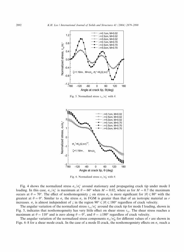
Fig. 5. Normalized stress sxy=rþI with h.
-180 -120 -60 0 60 120 180-3
-2
-1
0
1
2
3
M=c/cs
II+=KII/(2,π r)1/2,
ζ=1.19/m ,
: r=0.1cm, M=0.02: r=2.5cm, M=0.02: r=5.0cm, M=0.02: r=0.1cm, M=0.70: r=2.5cm, M=0.70: r=5.0cm, M=0.70
Nor
mal
ized
stre
ss, σ
x/σII+
Angle at crack tip, θ (deg)
σ
Fig. 6. Normalized stress rx=rþII with h.
2892 K.H. Lee / International Journal of Solids and Structures 41 (2004) 2879–2898
Fig. 4 shows the normalized stress ry=rþI around stationary and propagating crack tip under mode I
loading. In this case, ry=rþI is maximum at h ¼ 60� when M ¼ 0:02, where as for M ¼ 0:7 the maximum
occurs at h ¼ 70�. The effect of nonhomogeniety 1 on stress ry is more significant for jhj6 80� with thegreatest at h ¼ 0�. Similar to rx the stress ry in FGM is greater than that of an isotropic material as rincreases. ry is almost independent of 1 in the region 90�6 jhj6 180� regardless of crack velocity.
The angular variation of the normalized stress sxy=rþI around the crack tip for mode I loading, shown in
Fig. 5, indicates that nonhomogeneity has very little effect on shear stress sxy . The shear stress reaches a
maximum at h ¼ 110� and is zero along h ¼ 0�, and h ¼ �180� regardless of crack velocity.
The angular variation of the normalized stress components rij=rþII for different values of r are shown in
Figs. 6–8 for a shear mode crack. In the case of a mode II crack, the nonhomogeniety effects on rx reach a

-180 -120 -60 0 60 120 180-1.0
-0.8
-0.6
-0.4
-0.2
0.0
0.2
0.4
0.6
0.8
1.0
1.2
M=c/csσII
+ =KII/(2,π r)1/2,
: r=0.1cm, M=0.02: r=2.5cm, M=0.02: r=5.0cm, M=0.02: r=0.1cm, M=0.70: r=2.5cm, M=0.70: r=5.0cm, M=0.70
ζ=1.19/m
Nor
mal
ized
stre
ss, σ
y/σII+
Angle at crack tip, θ (deg)
Fig. 7. Normalized stress ry=rþII with h.
-180 -120 -60 0 60 120 180-0.2
0.0
0.2
0.4
0.6
0.8
1.0
1.2
1.4
1.6
1.8M=c/cs
σII+=KII/(2,π r)1/2
: r=0.1cm, M=0.02: r=2.5cm, M=0.02: r=5.0cm, M=0.02: r=0.1cm, M=0.70: r=2.5cm, M=0.70: r=5.0cm, M=0.70
ζ=1.19/m
Nor
mal
ized
stre
ss, τ
xy/σ
II+
Angle at crack tip, θ (deg)
Fig. 8. Normalized stress sxy=rþII with h.
K.H. Lee / International Journal of Solids and Structures 41 (2004) 2879–2898 2893
maximum at h ¼ 180� and increase with increasing r as shown in Fig. 6. In the case of ry , the effect of 1 isvery little as Fig. 5. In the case of shear stress sxy , the nonhomogeneity effects are dominant around h ¼ 140�and jhj6 60�, with the maximum effect seen at h ¼ 0�.
4.2. Isochromatics in FGMs
Isocromatics are generated by the stress optic law (Eq. (42)) combined with stress fields.
ffiffiffiffiffiffiffiffiffiffiffiffiffiffiffiffiffiffiffiffiffiffiffiffiffiffiffiffiffiffiffiffiffiffiðrx � ryÞ2 þ 4s2xyq¼ Nfr
hð42Þ
where N is the fringe order, h the plate thickness and fr the material fringe constant.

2894 K.H. Lee / International Journal of Solids and Structures 41 (2004) 2879–2898
In generating these contours, the stress intensity factor KI and KII were set to 1.0 MPaffiffiffiffim
pand 0.5 MPaffiffiffiffi
mp
, respectively, and a material fringe constant f of 6500 N/m-fringe and thickness of h ¼ 9:5 mm were
assumed. The remote stress in the x direction rox was set to zero.
Fig. 9 shows the opening mode isochromatics for a homogeneous material (1 ¼ 0) and for two values of1 around a stationary crack tip. One can observe from the contours shown in Fig. 9 that the fringes for a
homogeneous material are upright. However, the contours for nonhomogeneous materials, due to non-
homogeneity away from the crack tip, tilt away or towards the crack face depending on the sign of 1. When
1 > 0 (the modulus increases ahead of the crack), the fringes tilt forward whereas for 1 < 0, the fringes tilts
backward. The tilt is more predominant away from the crack-tip. As r approaches 0, the fringes regain their
classical form (upright), indicating that the stress components in an FGM are the same as that in isotropic
materials only very close to the crack tip.
Fig. 10 shows the isochromatic fringe patterns for a propagating crack tip (M ¼ 0:7) for the same valueof K used to generate Fig. 9. Generally isochromatic fringes for fast propagating cracks tilt more towards
the crack face (backward) compared to those for a stationary crack. As shown in Fig. 10, the backward tilt
of the fringe patterns for a propagating crack is greater when 1 < 0 compared to that when 1 > 0. This is
because the forward tilt due to a positive 1 compensates for a portion of the backward tilt due to the crack
speed.
Fig. 11 shows the shear mode isochromatic fringe patterns for a stationary crack in an FGM generated
using a KII ¼ 0:5 MPaffiffiffiffim
p. When the FGM constant 1 is zero, the fringes are symmetrical about the y axis.
However, when the FGM constant 1 > 0, the fringes enlarge forward, whereas when FGM constant 1 < 0,
Fig. 9. Isochromatic fringe patterns obtained for a static crack tip in an exponential variation of elastic and physical properties under
KI ¼ 1:0 MPaffiffiffiffim
p, f ¼ 6:5 kN/m, h ¼ 9:5 mm and rx2 ðroxÞ ¼ 0. (a) 1 ¼ 0, M ¼ 0:02; (b) 1 ¼ 1:19, M ¼ 0:02; (c) 1 ¼ �1:19, M ¼ 0:02.
Fig. 10. Isochromatic fringe patterns obtained for a propagating crack tip in an exponential variation of elastic and physical properties
under KI ¼ 1:0 MPaffiffiffiffim
p, f ¼ 6:5 kN/m. (a) 1 ¼ 0, M ¼ 0:7; (b) 1 ¼ 1:19, M ¼ 0:7; (c) 1 ¼ �1:19, M ¼ 0:7.

K.H. Lee / International Journal of Solids and Structures 41 (2004) 2879–2898 2895
the fringe enlarges backward. The results are representative of the fact that the shear modulus increases in
the þx direction when 1 > 0 and decreases in the �x direction when 1 < 0.
Fig. 12 shows the isochromatic fringe patterns for the propagating crack tip with M ¼ 0:7 for the same
KII. Similar to Fig. 11, the fringes enlarge more backward when 1 < 0 compared to that for 1 > 0.Fig. 13(a) and (b) shows the opening mode isochromatic fringe patterns for a linear variation of elastic
properties with a constant density for the same value of K used to generate Fig. 9. Considering crack length
Fig. 11. Isochromatic fringe patterns obtained for a static crack tip in an exponential variation of elastic and physical properties under
KII ¼ 0:5 MPaffiffiffiffim
p, f ¼ 6:5 kN/m. (a) 1 ¼ 0, M ¼ 0:02; (b) 1 ¼ 1:19, M ¼ 0:02; (c) 1 ¼ �1:19, M ¼ 0:02.
Fig. 12. Isochromatic fringe patterns obtained for a propagating crack tip in an exponential variation of elastic and physical properties
under KII ¼ 0:5 MPaffiffiffiffim
p, f ¼ 6:5 kN/m. (a) 1 ¼ 0, M ¼ 0:7; (b) 1 ¼ 1:19, M ¼ 0:7; (c) 1 ¼ �1:19, M ¼ 0:7.
Fig. 13. Isochromatic fringe patterns obtained for crack tip in a linear variation of elastic and properties with constant density.
(a) 1 ¼ 1:22, M ¼ 0:02; (b) 1 ¼ 1:22, M ¼ 0:7.

Fig. 14. Isochromatic fringe patterns obtained for crack tip in a linear variation of elastic and properties with constant density.
(a) 1 ¼ 1:22, M ¼ 0:02; (b) 1 ¼ 1:22, M ¼ 0:7.
2896 K.H. Lee / International Journal of Solids and Structures 41 (2004) 2879–2898
a ¼ 0:05 m, the FGM constant 1 for the linear variation of elastic properties when lðX Þ ¼ 1:316ð1þ 1X Þ is1:22=m, unlike 1:19=m for the exponential variation. Comparing Figs. 9 and 13 for stationary crack, the two
isochromatic fringe patterns are almost the same. For a propagating crackwithM ¼ 0:7, the isochromatic fringes
for the linear variation of elastic properties with constant density are also nearly the same as those for the
exponential variation of properties and density in�5 < x < 2 cm, but they are somewhat different for x > 2 cm.
Fig. 14(a) and (b) show shear mode isochromatic fringe patterns for linear variations in elastic properties
under a constant density for the same values of K used to generate Fig. 11. Comparing Figs. 11 and 14, theisochromatic fringes for the linear variation of elastic properties with constant density are somewhat greater
than those for the exponential variation of properties and density.
5. Summary of results
In the study, stress and displacement fields close to a propagating crack tip in an FGM which has (1) a
linear variation of shear modulus with constant density and Poisson�s ratio, and (2) an exponential vari-
ation of shear modulus and density under constant Poisson�s ratio, are developed. Experimental methodsused in fracture investigations employ such descriptions of the stress field to extract the stress intensity
factor from full-filed experimental data sampled from a region between the near field and far field. In this
intermediate region, a singular term and one or two higher order terms are sufficient to accurately describe
the stress field.
The analysis presented here indicates that at least three terms must be considered in the case of FGM in
order to explicitly account for the nonhomogeneity effects. The explicit form of the nonhomogeneity specific
higher order terms is developed for FGMs using which the characteristics of the stress fields and the effect of
nonhomogeniety on their structure is brought out. The results indicate that nonhomogeniety effects dependon the angular position of the point considered. The effects are dominant in the region around the crack-tip
from where experimental data is usually sampled, and hence, the nonhomogeneity specific terms presented
here must be included to obtain meaningful estimates of fracture parameters from experimental data.
Appendix A
Let complex variable z put as follows
z ¼ xþ my ðA:1Þ
where m is a variable dependent on crack propagation velocity and physical properties.
K.H. Lee / International Journal of Solids and Structures 41 (2004) 2879–2898 2897
Substituting Eq. (A.1) into Eq. (4) transformed with moving coordinates when 1 ¼ 0, we obtain
Eq. (A.2).
AðmÞU0001 þ mBðmÞW000
1 ¼ 0
mAðmÞU0001 � BðmÞW000
1 ¼ 0ðA:2Þ
where
AðmÞ ¼ l0ðk þ 2Þ ðm2
�þ 1Þ � qc2
l0ðk þ 2Þ
�; BðmÞ ¼ l0 ðm2
�þ 1Þ � qc2
l0
�
The characteristic equation of Eq. (A.2) is as follows
ðm2 þ 1Þ m2
�þ 1
�� qc2
l0ðk þ 2Þ
��m2
�þ 1
�� qc2
l0
��¼ 0 ðA:3Þ
The characteristic roots of positive number for the equation are as follows
m ¼ i; m ¼ ial; m ¼ ias ðA:4Þ
where, the root m ¼ i is independent of crack velocity and physical properties, it is only depend on relationbetween U0001 ðalÞ and W000
1 ðasÞ. Thus, the coefficients of U0001 ðalÞ and W000
1 ðasÞ in Eq. (A.2) are as follows.
m ¼ i; AðmÞ ¼ AðialÞ; BðmÞ ¼ BðiasÞ ðA:5Þ
Considering U0001 ðalÞ ¼ oog1
U001ðalÞ, mW000
1 ðasÞ ¼ oog2
W001ðasÞ and substituting Eq. (A.5) into Eq. (A.2) integrated
with z, we can obtain the relation between U1ðalÞ and W1ðasÞ.
oog2W1ðzsÞ ¼ � Aðm ! ialÞ
Bðm ! iasÞo
og1U1ðzlÞ ¼ �ðk þ 2Þ o
og1U1ðzlÞ ðA:6Þ
1
k þ 2
o
og1W1ðzsÞ ¼
o
og2U1ðzlÞ ðA:7Þ
where integral constants related to rigid displacement are ignored.
0.0 0.2 0.4 0.6 0.8 1.00.0
0.5
1.0
1.5
2.0
ν=0.33
A (α
l)/(k
+2)B
(αs)
Normalized crack velocity (c/cs)
Fig. 15. AðalÞ=½ðk þ 2ÞBðasÞ� with crack propagation velocity.

2898 K.H. Lee / International Journal of Solids and Structures 41 (2004) 2879–2898
We can confirm the AðalÞ=BðasÞ ¼ k þ 2 in Fig. 15 which obtained under subsonic crack velocity when
m ¼ 0:33.
References
Atkinson, C., List, R.D., 1978. Steady state crack propagation into media with spatially varying elastic properties. Int. J. Eng. Sci. 16,
717–730.
Butcher, R.J., Rousseau, C.E., Tippur, H.V., 1999. A functionally graded particulate composite: preparation, measurements, failure
analysis. Acta Mater. 47 (1), 259–268.
Eischen, J.W., 1987. Fracture of nonhomogeneous materials. Int. J. Fract. 34 (3), 3–22.
Erdogan, F., 1995. Fracture mechanics of functionally graded materials. Compos. Eng. 5 (7), 753–770.
Freund, L.B., 1990. Dynamic Fracture Mechanics. Cambridge University Press, Cambridge.
Gu, P., Dao, M., Asaro, R.J., 1999. A simplified method for calculating the crack-tip field of functionary graded materials using the
domain integrials. J. Appl. Mech. 66, 101–108.
Jedamzik, R., Neubrand, A., Rodel, J., 2000. Production of functionally graded materials from electrochemically modified carbon
preforms. J. Am. Ceram. Soc. 83 (4), 983–985.
Jiang, L.Y., Wang, X.D., 2002. On the dynamic crack propagation in an interphase with spatially varying elastic properties under
inplane loading. Int. J. Fract. 114, 225–244.
Jin, Z.H., Batra, R.C., 1996. Some basic fracture mechanics concept in functionally graded materials. J. Mech. Phys. Solids 44 (8),
1221–1235.
Niino, M., Hirai, T., Watanabe, R., 1987. The functionally gradient. J. Jpn. Soc. Compos. Mater. 13 (1), 257.
Parameswaran, V., Shukla, A., 1999. Crack-tip stress fields for dynamic fracture in functionally gradient materials. Mech. Mater. 31,
579–596.
Parameswaran, V., Shukla, A., 2000. Processing and characterization of a model functionally gradient material. J. Mater. Sci. 35, 21–
29.
Parameswaran, V., Shukla, A., 2002. Asymptotic stress fields for stationary cracks along the gradient in functionally graded materials.
J. Appl. Mech. 69, 240–243.
Rousseau, C.-E., Tippur, H.V., 2001. Dynamic fracture of compositionally graded materials with cracks along the elastic gradient
experiments and analysis. Mech. Mater. 33, 403–421.
Wang, X.D., Meguid, S.A., 1995. On the dynamic crack propagation in an interface with spatially varying elastic properties. Int. J.
Fract. 69, 87–99.
Zeng, Y.P., Jiang, D.L., Watanabe, T., 2000. Fabrication and properties of tape-cast laminated and functionally gradient alumina-
titanium carbide materials. J. Am. Ceram. Soc. 83 (12), 2999–3003.