chapter6 leak detection - bem-vindo
TRANSCRIPT

1
Chapter 6 Leak detection

2

3
mbar× l×s-1
tpVq L ∆
∆×=
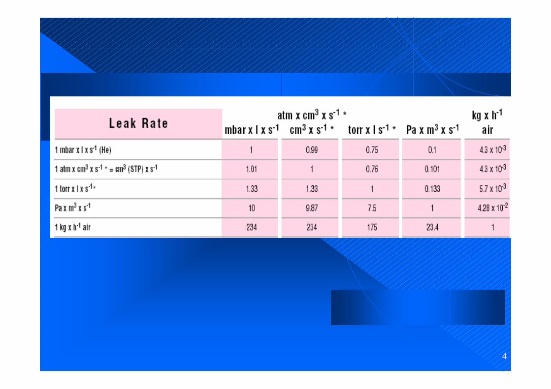
A leak rate of 1 mbar× l×s-1 exists in a closed vessel having a volume of 1 liter when the pressure increases by 1 mbar within one second, or in case of an overpressure it decreases by 1 mbar within one second.
1. Leak rate
4
5
2. Leak Detection Methods
Vacuum Methods
The equipment to be tested is evacuated. The pressure ratio between inside and outside is 0:1.
Overpressure Methods
The equipment to be tested is pressurized with a search gas or a search gas mixture. The pressure ratio between inside and outside is over 1:1.

6
General Notes
1. The lowest leak rates can only be measured by employing the vacuum method, whereby the following applies: The lower the leak rate, the higher the requirements are concerning cleanness and ultimate vacuum.
2. If possible the test objects should be tested under the sameconditions that will be used in their final application, i.e. parts for vacuum operation should be tested according to the vacuum method and parts for overpressure operation should be tested using the overpressure method.

7
2.1 Leak Testing Based on Vacuum Methods
1. Pressure Rise Method
a) shows the theoretical pressure rise if there is only a leak.
b) shows the pressure rise due to outgassing from the surfaces of the test object.
c) shows the pressure rise as it occurs in practice, where outgassing and leak rate add.

8
2. Local Leak Detection
1 Test object 2 Leak detector 3 Search gas cylinder
4 Vacuum pump 5 Spray gun for search gas

9
1 Test object 2 Leak detector 3 Search gas cylinder
4 Vacuum pump 5 Hood 6 Spray gun for search gas 7 Sniffer probe
3. Integral Method

10
2.2 Leak Testing Based on Overpressure Methods
1. Pressure Drop Method
The test object is filled with a gas
determination of gross leaks
applying soap solutions or similar, leaks can be located.

11
1 Test object 2 Leak detector 3 Search gas cylinder 7 Sniffer probe
2. Local Leak Detection with Leak Detectors – Sniffing
12
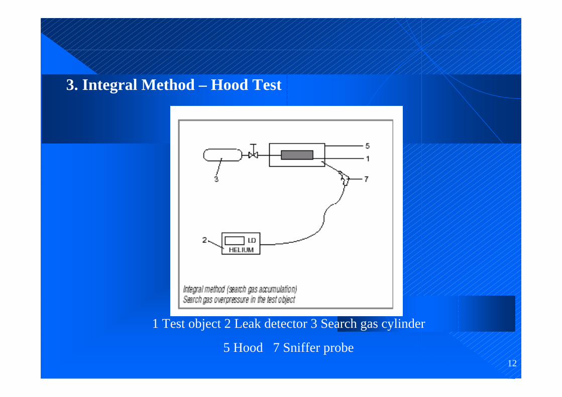
3. Integral Method – Hood Test
1 Test object 2 Leak detector 3 Search gas cylinder
5 Hood 7 Sniffer probe

13
4. Integral Method – Vacuum Hood Test
1 Test object 2 Leak detector 3 Search gas cylinder
4 Vacuum pump 5 Hood

14
5. Integral Method – Bombing-TestThis method is used for testing hermetically sealed components such as transistors, IC-packages or dry reed relays.
Operating principle:1.The test objects are placed in a vessel which is pressurized with the search gas - preferably helium.
2. At a fairly high search gas pressure and after a period of up to several hours it is tried to enrich the search gas inside leaky test objects.
3. After this, the test objects are transferred to a vacuum chamber
4. Their total leak rate is determined in the same way as in the vacuum hood test.

15
3. Helium Leak Detectors
3.1. Applications:a. Localization of leaks b. Quantitative determination of the leak rate, i.e. the gas flow through the leak.A leak detector is therefore a helium flow meter.

16
3.2 Operating Principle
a. Evacuating the part which is to be tested.
b. Gas from the outside may enter through an existing leak due to the pressure difference present.
c. If only helium is brought in front of the leak , this helium flows through the leak and is pumped out by the leak detector.
d. The helium partial pressure present in the leak detector is measured by a sector mass spectrometer and is displayed as a leak rate.
e. Leak rate. is usually given in terms of volume flow of the helium (pV-flow).

17
3.3 Parameters of helium leak detector
• Measurement range (detection limits)
The lowest and the highest detectable leak rate The sum of noise amplitude and zero drift per minute
• Response time.
Time it takes from spraying the test object with helium until a measured value is displayed by the leak detector.
Response time for helium tA = 3V/SHe (for 95% of the final value)
with V = Volume of the test object
SHe = Volume flow rate for helium at the point of the test object

18
3.4 Operation mode
1. Main Flow Method
2. Counterflow Method
3. Partial Flow Method

19
Main Flow MethodAdvantages:
Highest sensitivity, i.e. low detection limit
Short response time due to a high volume flow rate at the inlet.
Disadvantage
a liquid nitrogen cold trap

20
Counterflow Method
•The test object is connected to the forevacuum •The entire gas flow (especially water vapor) does not contribute to the pressure increase in the mass spectrometer. •A cold trap is no longer required!
Advantages:
No liquid nitrogen is required
High permissible inlet pressures (i.e. pressure within the test object)

21
Partial Flow Method
Higher leak rates Operation at higher inlet pressures
At pressures above the normal inlet pressure (main flow: above 10-2 mbar, counterflow: above 10-1 mbar)In the case of high helium leak rates,The inlet valve is closed The main flow is allowed to enter the partial flow pump, whereas only a small part enters the leak detector.Thus the total pressure and the helium pressure are dropped to values suitable for operation of the leak detector. .