chapter6 6 deutschmann revised withfigs - kit - itcp ... · pdf file6.6.1 introduction ......
TRANSCRIPT
6.6 Computational Fluid Dynamics Simulation of Catalytic Reactors
O. Deutschmann
6.6.1 Introduction
Catalytic reactors are generally characterized by the complex interaction of various physical
and chemical processes. Monolithic reactors can serve as example, in which partial oxidation
and reforming of hydrocarbons, combustion of natural gas, and the reduction of pollutant
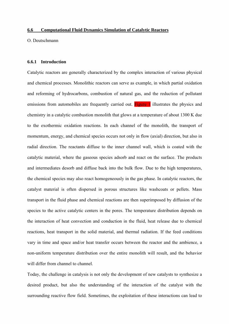
emissions from automobiles are frequently carried out. Figure 1 illustrates the physics and
chemistry in a catalytic combustion monolith that glows at a temperature of about 1300 K due
to the exothermic oxidation reactions. In each channel of the monolith, the transport of
momentum, energy, and chemical species occurs not only in flow (axial) direction, but also in
radial direction. The reactants diffuse to the inner channel wall, which is coated with the
catalytic material, where the gaseous species adsorb and react on the surface. The products
and intermediates desorb and diffuse back into the bulk flow. Due to the high temperatures,
the chemical species may also react homogeneously in the gas phase. In catalytic reactors, the
catalyst material is often dispersed in porous structures like washcoats or pellets. Mass
transport in the fluid phase and chemical reactions are then superimposed by diffusion of the
species to the active catalytic centers in the pores. The temperature distribution depends on
the interaction of heat convection and conduction in the fluid, heat release due to chemical
reactions, heat transport in the solid material, and thermal radiation. If the feed conditions
vary in time and space and/or heat transfer occurs between the reactor and the ambience, a
non-uniform temperature distribution over the entire monolith will result, and the behavior
will differ from channel to channel.
Today, the challenge in catalysis is not only the development of new catalysts to synthesize a
desired product, but also the understanding of the interaction of the catalyst with the
surrounding reactive flow field. Sometimes, the exploitation of these interactions can lead to
2
the desired product selectivity and yield. Hence, it is not surprising that a report on chemical
industrial technology in the year 2020 [1] has identified a better understanding of gas-solid
flows in chemical reactors as a critical need, and calls for the development of reliable
simulation tools that integrate detailed models of reaction chemistry and computational fluid
dynamics (CFD) modeling of macro-scale flow structures.
Computational fluid dynamics is able to predict very complex flow fields, even combined
with heat transport, due to recently developed numerical algorithms and the availability of
faster and bigger (memory) computer hardware. The consideration of detailed models for
chemical reactions, in particular for heterogeneous reactions, however, is still very
challenging due to the large number of species mass conservation equations, their highly non-
linear coupling, and the wide range of time scales introduced by the complex reaction
networks.
This chapter introduces the application of CFD simulations to obtain a better understanding of
the interactions between mass and heat transport and chemical reactions in catalytic reactors.
Concepts for modeling and numerical simulation of catalytic reactors are presented, which
describe the coupling of the physical and chemical processes in detail. The ultimate objective
of these approaches is to understand and, eventually, to optimize the behavior of the catalytic
reactor. Though computational fluid dynamics covers a wide range of problems, reaching
from the simulation of the flow around airplanes to laminarization of turbulent flows entering
a micro channel, this chapter focuses on the principal ideas and the potential applications of
CFD in heterogeneous catalysis; textbooks and specific literature are frequently referenced for
more details. It should also be mentioned that the limiting space does not allow the review of
all studies, which led to much progress in simulation of catalytic reactors in the last decade.
3
6.6.2 Modeling of reactive flows
6.6.2.1 Governing equations of multi-component flows
As long as a fluid can be treated as a continuum, the most accurate description of the flow
field of multi-component mixtures is given by the transient three-dimensional (3D) Navier-
Stokes equations coupled with the energy and species governing equations, which will be
summarized in this chapter. More detailed introductions into fluid dynamics and transport
phenomena can be found in a number of textbooks [2-6]. The recently published textbook by
Kee et al. [2] also emphasizes on the coupling of flow fields with heterogeneous reactions.
Other alternative concepts such as Lattice-Boltzmann models have also been discussed for
simulation of catalytic reactors as introduced in Section 6.6.5.1.
Governing equations, which are based on conservation principles, can be derived by
consideration of the flow within a certain spatial region, which is called the control volume.
The principle of mass conservation leads to the mass continuity equation
( )mS
xv
t i
i =∂
∂+
∂∂ ρρ , (1)
with ρ being the mass density, t the time, xi (i=1,2,3) are the Cartesian coordinates, and vi the
velocity components. The source term Sm vanishes unless mass is either deposited on or
ablated from the solid surfaces. The Einstein convention is used here, i.e., whenever the same
index appears twice in any term, summation over that index is implied, except if the index
refers to a chemical species. The principle of momentum conservation for Newtonian fluids
leads to three scalar equations for the momentum components ρ vi
( ) ( )i
j
ij
ij
jii gxx
px
vvtv
ρτρρ
=∂
∂+
∂∂
+∂
∂+
∂∂
, (2)
where p is the static pressure, τij is the stress tensor, gi are the components of the gravitational
acceleration. Gravity, the only body force taken into account, can often be neglected when
modeling catalytic reactors. The stress tensor is given as

4
k
kij
i
j
j
iij x
vxv
xv
∂∂
⎟⎠⎞
⎜⎝⎛ −+⎟
⎟⎠
⎞⎜⎜⎝
⎛
∂
∂+
∂∂
−= δκµµτ32 . (3)
Here, κ and µ are the bulk viscosity and mixture viscosity, respectively, and δij is the
Kronecker delta, which is unity for i=j, else zero. The bulk viscosity vanishes for low density
mono-atomic gases and is also commonly neglected for dense gases and liquids [3]. The
coupled mass continuity and momentum governing equations have to be solved for the
description of the flow field.
In multi-component mixtures, not only the flow field is of interest but also mixing of the
chemical species and reactions among them, which can be described by an additional set of
partial differential equations. Here, the mass mi of each of the Ng gas-phase species obeys a
conservation law that leads to
( ) ( ) ( ) hom,i
j
ji
j
iji Rxj
xYv
tY
=∂
∂+
∂∂
+∂
∂ ρρ , (4)
with Yi is the mass fraction of species i in the mixture (Yi = mi/m) with m as total mass, Rihom is
the net rate of production due to homogeneous chemical reactions. The components ji,j of the
diffusion mass flux caused by concentration and temperature gradients are often modeled by
the mixture-average formulation [7]:
j
i
j
ii
i
iji x
TTD
xXD
XYj
∂∂
−∂∂
−=T
M, ρ . (5)
DiM is the effective diffusion coefficient of species i in the mixture, Di
T is the thermal
diffusion coefficient, which is significant only for light species. T is the temperature. The
molar fraction Xi is related to the mass fraction Yi using the species molar masses Mi by
i
i
N
j j
ji M
Y
MYX
∑ =
=g
1
1 . (6)

5
Heat transport and heat release due to chemical reactions lead to spatial and temporal
temperature distributions in catalytic reactors. The corresponding governing equation for
energy conservation is commonly expressed in terms of the specific enthalpy h:
( ) ( )h
, Sxv
xpv
tp
xj
xhv
th
k
jjk
jj
j
jq
j
j +∂
∂−
∂∂
+∂∂
=∂
∂+
∂
∂+
∂∂ τ
ρρ , (7)
with Sh being the heat source, for instance due to thermal radiation. In multi-component
mixtures, diffusive heat transport is significant due to heat conduction and mass diffusion,
hence
∑=
+∂∂
−=g
1,,
N
ijii
jjq jh
xTj λ . (8)
λ is the thermal conductivity of the mixture. The temperature is then related to the enthalpy by
the definition of the mixture specific enthalpy
( )∑=
=g
1
N
iii ThYh , (9)
with hi being the specific enthalpy of species i, which is a monotonic increasing function of
temperature. The temperature is then commonly derived from Eq. (9) for known h and Yi.
Heat transport in solids such as reactor walls and catalyst materials can also be modeled by an
enthalpy equation, for instance in the form of
( )hS
xT
xth
jj
=⎟⎟⎠
⎞⎜⎜⎝
⎛
∂∂
∂∂
−∂
∂ λρ , (10)
where h is the specific enthalpy and λ the thermal conductivity of the solid material. Sh
accounts for heat sources, for instance due to heat release by chemical reactions and electric
or radiative heating of the solid.
This system of governing equations is closed by the equation of state to relate the
thermodynamic variables density ρ, pressure p, and temperature T. The simplest model of this
relation for gaseous flows is the ideal gas equation

6
∑=
=g
1
N
iiiMX
RTp ρ , (11)
with the universal gas constant R = 8.314 J mol-1 K-1.
The transport coefficients µ, DiM, Di
T, and λ appearing in Eqs. (3, 5, 8) depend on temperature
and mixture composition. They are derived from the transport coefficients of the individual
species and the mixture composition by applying empirical approximations [2, 3, 5], which
eventually lead to two physical parameters for each species, a characteristic diameter, σi, and
a characteristic energy, εi, which can be taken from data bases [8].
The specific enthalpy hi is a function of temperature and can be expressed in terms of the heat
capacity
( ) ∫ ′′+=T
Tipii TTcThh
ref
d)(,ref , (12)
where cp,i is the specific heat capacity at constant pressure. The specific standard enthalpy of
formation ∆h0f,298,i can be used as integration constant hi(Tref = 298.15 K, p0 = 1 bar).
Experimentally determined and estimated standard enthalpies of formation, standard
entropies, and temperature dependent heat capacities can be found in data bases [9-11] or
estimated by Benson’s additivity rules [12].
6.6.2.2 Turbulent flows
Turbulent flows are characterized by continuous fluctuations of velocity, which can lead to
fluctuations in scalars such as density, temperature, and mixture composition. Turbulence can
be desired in catalytic reactors to enhance mixing and reduce mass transfer limitations but is
also unwanted due to the increased pressure drop and energy dissipation. An adequate
understanding of all facets of turbulent flows is still missing [5, 13, 14]. In the area of catalytic
systems, some progress had been made recently in turbulent flow modeling, e.g. in
catalytically stabilized combustion [15, 16]. The Navier-Stokes equations as presented above are

7
in principal able to model turbulent flows (Direct Numerical Simulation). However in
practice, the solutions of the Navier-Stokes equations for turbulent flows in technical reactors
demand a prohibitive amount of computational time due to the huge number of grid points
needed to resolve the small scales of turbulence. Therefore, several concepts were developed
to model turbulent flows by the solution of averaged governing equations. However, the
equation system is not closed, that means a model has to be set up to describe the so-called
Reynold stresses that are the correlations between the velocity fluctuations and the
fluctuations of all the quantities of the flow (velocity, enthalpy, mass fractions). The k - ε -
model [17] is the currently most widely used concept for modeling the Reynold stresses, which
adds two additional partial differential equations for the description of the turbulent kinetic
energy, k, and the dissipation rate, ε, to the governing equations. Although the model has
well-known deficiencies, it is today implemented in most commercial CFD codes and also
widely used for the simulation of catalytic reactors. Recently, turbulent flow field simulations
are often based on Large-Eddy-Simulation (LES), which combines DNS for the larger scales
with a turbulence model, e.g. k - ε - model, for the unresolved smaller scales.
Aside form this closure problem, one still has to specify the averaged chemical reaction rates
[5, 13]. Due to the strong non-linearity of the rate coefficients (Eq. 14), the source terms of
chemical reactions in turbulent flows cannot be computed using average concentrations and
temperature. Here, probability density functions (PDFs) [5], either derived by transport
equations [14] or empirically constructed [18], are used to take the turbulent fluctuations into
account when calculating the chemical source terms. For the simulation of reactions on
catalysts, it is important to use appropriate models for the flow laminarization at the solid
surface.

8
6.6.2.3 Homogeneous chemical reactions in the gas phase
In many catalytic reactors, the reactions do not exclusively occur on the catalyst surface but
also in the fluid flow. In some reactors even the desired products are mainly produced in the
gas phase, for instance in the oxidative dehydrogenation of paraffins to olefins over noble
metals at short contact times and high temperature [19-26]. Such cases are dominated by the
interaction between gas-phase and surface kinetics and transport. Therefore, any reactor
simulation needs to include an appropriate model for the homogeneous kinetics along with the
flow models. The species governing equations (4) contain a source term Rihom, which is the
specific net rate of production of species i due to homogeneous chemical reactions.
Considering a set of Kg chemical reactions among Ng species Ai
∑∑==
′′→′g
11
N
iiik
N
iiik AA
g
νν , (13)
with ikν ′ , ikν ′′ being the stoichiometric coefficients, and an Arrhenius-like rate expression,
( )11aexp −−− TREAT β , this source term can be expressed by
∏∑==
⎟⎟⎠
⎞⎜⎜⎝
⎛⎥⎦
⎤⎢⎣
⎡−′−′′=
gg
11
ahom exp )(N
j
a
j
jK
kkikikii
jk
kk
MY
RTE
TAMRρ
νν β . (14)
Here, Ak is the pre-exponential factor, βk is the temperature exponent, k
Ea is the activation
energy, and ajk is the order of reaction k related to the concentration of species j. Various
reliable sets of elementary reactions are available for modeling homogeneous gas phase
reactions, for instance for total [5] and partial oxidation, and pyrolysis of hydrocarbons. The
advantage of the application of elementary reactions is that the reaction orders ajk in Eq. (14)
equal the stoichiometric coefficients jkν ′ .
Even though the implementation of Eq. (14) is straight forward, an additional highly
nonlinear coupling is introduced into the governing equations leading to considerable
computational efforts. The nonlinearity, the large number of chemical species, and the fact

9
that chemical reactions exhibit a large range of time scales make the solution of those
equation systems challenging. In particular for turbulent flows, but sometimes even for
laminar flows, the solution of the system is too CPU time-consuming with current numerical
algorithms and computer capacities. This calls for the application of reduction algorithms for
large reaction mechanisms, for instance by the extraction of the intrinsic low dimensional
manifolds of trajectories in chemical space [27], which can be applied for heterogeneous
reactions [28] . Another approach is to use “as little chemistry as necessary”. In these so-called
adaptive chemistry methods, the construction of the reaction mechanism includes only steps
relevant for the application studied [29].
6.6.3 Modeling surface reaction rates
6.6.3.1 Coupling with the flow field
Depending on the spatial resolution of the catalytic layer the species mass fluxes due to
catalytic reactions are differently coupled with the flow field.
In the first case considered the catalytic layer can be resolved in space. Examples are
catalytically coated walls in honeycomb structures (Fig. 1), disks, and plates and well-defined
porous media (fixed bed reactors, foams, washcoats), in which the shape of the individual
pellet or channel is known. The chemical processes at the surface are then coupled with the
surrounding flow field by boundary conditions for the species-continuity equations, Eqs. (4),
at the gas-surface interface [2, 30]:
hetStef )( iii RYvjn =+rrr ρ (15)
Here nr is the outward-pointing unit vector normal to the surface, ijr
is the diffusion mass flux
of species i as discussed in Eqs. (4), and hetiR is the heterogeneous surface reaction rate, which
is given per unit geometric surface area, corresponding to the reactor geometry, in kg m-2 s-1.

10
The Stefan velocity Stefvr occurs at the surface if there is a net mass flux between the surface
and the gas phase:
∑=
=g
1
hetStef
1 N
iiRvn
ρrr . (16)
At steady-state conditions, this mass flux vanishes unless mass is deposited on the surface,
e.g. chemical vapor deposition, or ablated, e.g. material etching. Equation (15) basically
means that for Stefvr = 0 the amount of gas-phase molecules of species i, which are
consumed/produced at the catalyst by adsorption/desorption, have to diffuse to/from the
catalytic wall (Eq. 5). Only for fast transient (< 10-4 s) adsorption/desorption processes, e.g.
during ignition of catalytic oxidation, Eq. (15) breaks down and special treatment of the
coupling is needed [31, 32].
The calculation of hetiR requires the knowledge of the amount of catalytically active surface
area in relation to the geometric surface area, here denoted by cat/geoF , at the gas-surface
interface:
iii sMFR &cat/geohet η= (17)
Here, is& is the molar net production rate of gas phase species i, given in mol m-2 s-1; the area
now refers to the actual catalytically active surface area. cat/geoF can be determined
experimentally, e.g. by chemisorption measurements. The effect of internal mass transfer
resistance for catalyst dispersed in a porous media is included by the effectiveness factor η [6,
33]. More detailed models for transport in porous media are discussed in Section 6.6.4.
In most fixed bed reactors with large numbers of catalytic pellets, for non-trivial shapes of the
catalysts, and for catalyst dispersed in porous media, the structure of the catalyst can not be
resolved geometrically. In those cases, the catalytic reaction rate is expressed per volumetric
unit, that means hetiR is now given in kg m-3 s-1; the volume here refers to the volume of a

11
computational cell in the in the geometrical domain of fluid flow. Then hetiR simply represents
an additional source term on the right side of the species-continuity equation, Eq. (4), and is
computed by
iii sMSR &Vhet η= , (18)
where VS is the active catalytic surface area per volumetric unit, given in m-1, determined
experimentally or estimated. cat/geoF as well as VS can be expressed as function of the reactor
position and time to account for in-homogeneously distributed catalysts and loss of activity,
respectively. In reactors with more than one catalytic material, a different value for cat/geoF or
VS can be given for every individual active material or phase, respectively.
6.6.3.2 Modeling the surface reaction rate
Since the rate of catalytic reactions is very specific to the catalyst formulation, global rate
expressions have been used for many years [6, 34]. The reaction rate has often been based on
catalyst mass, catalyst volume, reactor volume, or catalyst external surface area. The
implementation of this macro kinetic approach is straightforward; the rate is& can easily be
expressed by any arbitrary function of gas-phase concentrations and temperature at the
catalysts surface calculated at any computational cell containing either catalytically active
particles or walls. It is evident that this approach cannot account for the complex variety of
phenomena of catalysis and that the rate parameters must be evaluated experimentally for
each new catalyst and various external conditions.
Since measuring and modeling surface reaction rates is thoroughly discussed in many
Chapters of this Handbook, at this point only the concept of the mean-field approximation is
discussed in the remainder of this section. This concept currently is state of the art in CFD
modeling of catalytic reactors and implemented in a variety of CFD codes.

12
A Mean field approximation and reaction kinetics
The mean field approximation is related to the size of the computational cell in the flow field
simulation assuming that the local state of the active surface can be represented by mean
values for this cell. Hence, this model assumes randomly distributed adsorbates on the
surface, which is viewed as being uniform. The state of the catalytic surface is described by
the temperature T and a set of surface coverages θi, that is the fraction of the surface covered
with surface species i. The surface temperature and the coverages depend on time and the
macroscopic position in the reactor, but are averaged over microscopic local fluctuations.
Under those assumptions a chemical reaction can be defined in analogy to Eq. (13) by
∑∑++
=
++
=
′′→′bsgbsg
11
NNN
iiik
NNN
iiik AA νν (19)
The difference is that now the iA denote not only gas-phase species (e.g., H2) but also surface
species (e.g., H(s)) and bulk species (e.g., H(b)). The Ns surface species are those that are
adsorbed on the top mono-atomic layer of the catalytic particle while the Nb bulk species are
those found in the inner solid catalyst.
Steric effects of adsorbed species and various configurations, e.g., the type of the chemical
bonds between adsorbate and solid, can be taken into account using the following concept:
The surface structure is associated with a surface site density Γ that describes the maximum
number of species that can adsorb on a unit surface area, given, e.g., in mol m-2. Then each
surface species is associated with a coordination number σi describing the number of surface
sites which are covered by this species. Under the assumptions made, a multi-step (quasi-
elementary) reaction mechanism can be set up. The molar net production rate is& is then given
as
∏∑++
==
=bsg 's
11f
NNN
jj
K
kiki
jk
kcks νν& . (20)

13
Here, Ks is the number of surface reactions, ci are the species concentrations, which are given,
e.g., in mol m-2 for the Ns adsorbed species and in, e.g., mol m-3 for the Ng and Nb gaseous and
bulk species. According to Eq. (20) and the relation 1−=Θ Γc iii σ , the variations of surface
coverages follow
Γs
tΘ iii σ&
=∂
∂. (21)
Since the reactor temperature and concentrations of gaseous species depend on the local
position in the reactor, the set of surface coverages also varies with position. However, no
lateral interaction of the surface species between different locations on the catalytic surface is
modeled. This assumption is justified by the fact that the computational cells in reactor
simulations are usually much larger than the range of lateral interactions of the surface
processes. In each of these cells, the state of the surface is characterized by mean values
(mean-field approximation). The set of differential equations (21) has to be solved
simultaneously with flow field equations for every computational cell containing catalytic
material. At steady state, the left sides of Eqs. (21) become zero, and a set of algebraic
equations has to be solved. The time scales to reach the steady state of Eqs. (21) are
commonly much shorter than the time scales of significant variations of species
concentrations and temperature in the fluid. Therefore, a quasi-steady state assumption with
vanishing left sides of Eqs. (21) is frequently justified even for transient reactor operation.
The binding states of adsorption of all species vary with the surface coverage. This additional
coverage dependence is modeled in the expression for the rate coefficient k
kf in Eq. (20) by
two additional parameters, ki
µ and ki
ε [2, 30]:
∏=
⎥⎦
⎤⎢⎣
⎡⎥⎦
⎤⎢⎣
⎡−=
s
1
af exp exp
N
i
iiik RT
ΘΘ
RTE
TAk kkikk
k
εµβ . (22)
For adsorption reactions sticking coefficients are commonly used, which can be converted to
conventional rate coefficients [2, 35] by

14
∑=
′=Γ
=s
1
0adsf where,
2
N
jjk
i
i
MRTSk
kντ
πτ . (23)
0iS is the initial (uncovered surface) sticking coefficient.
B Development of multi-step surface reaction mechanisms
The development of a reliable surface reaction mechanism is a complex process following the
scheme given in Fig. 2. A tentative reaction mechanism can be proposed based on
experimental surface science studies, on analogy to gas-phase kinetics and organo-metallic
compounds, and on theoretical studies, increasingly including DFT calculations [36, 37]. This
mechanism should include all possible paths for the formation of the chemical species under
consideration in order to be “elementary-like” and thus applicable over a wide range of
conditions. The mechanism idea then needs to be evaluated by numerous experimentally
derived data, which are compared with theoretical predictions based on the mechanism. Here,
the simulations of the laboratory reactors require appropriate models for all significant
processes in order to evaluate the intrinsic kinetics. Sensitivity analysis leads to the crucial
steps in the mechanism, for which refined kinetic experiments and data may be needed.
Since the early nineties, many groups have developed surface reaction mechanisms following
the concepts discussed above. In particular oxidation reactions over noble metals have been
modeled extensively such as of hydrogen [38-44], CO [45-47], and methane [31, 48-52] and ethane [22,
26, 53, 54] over Pt, formation of synthesis gas over Rh [52, 55]. Lately, mechanisms have been
established for more complex reaction systems, for instance, three-way catalysts [56] or
Chemical Vapor Deposition (CVD) reactors for the formation of diamond [57, 58], silica [59],
and nanotubes [60]. A crucial issue with many of the mechanisms published is thermodynamic
consistency. Even though most of the mechanisms lead to consistent enthalpy diagrams, many
are not consistent regarding the entropy change in the overall reaction due to missing
knowledge on the transition states of the individual reactions and therefore on the pre-

15
exponentials in the rate equations. Lately, optimization procedures enforcing overall
thermodynamic consistency have been applied to overcome this problem [61].
C Limitation of the models and alternate approaches
Catalytic surfaces are certainly non-uniform; site heterogeneity exists because the surface of
practical catalyst particles is characterized by terraces of different crystal structures, steps,
edges, additives, impurities, and defects. In the method (mean-field approximation) discussed
above, the site heterogeneity was averaged out by mean rate coefficients. If the distribution of
the different types of adsorption sites and the reaction kinetics on those sites are known, the
concept discussed can easily be used to set up a reaction mechanism, which consists of
several sub-mechanisms for the different surface structures [30]. This concept was applied in
the framework of a two-adsorption site model for the simulation of CO combustion on
polycrystalline Pt [62]. The site heterogeneity can be described by the probability that an
arbitrary site is characterized by the associated reaction kinetics. In the models discussed so
far, this probability function is a sum over a finite number of surface structures, but also
continuous functions are used in literature [63]. Here, the problem again is the limited
knowledge of the distribution of the different types of surface patches and the kinetics on
these patches.
Effects resulting from lateral interactions of the adsorbates are inherently more difficult to
treat. In the mean-field approximation they are either neglected or incorporated by mean rate
coefficients. If the specific adsorbate-adsorbate interactions are understood quantitatively,
then a Monte Carlo (MC) simulation of the surface chemistry can be carried out [64]. MC
simulations at various temperatures and gas-phase concentrations lead to apparent activation
energies and reaction orders. In catalytic combustion, a real time-dependent MC simulation
including the surrounding flow field was recently carried out for CO oxidation on Pt and
compared with simulations using the mean-field approximation [65]. Even though MC

16
calculations offer great promise for the understanding of complex surface phenomena, the
application of these calculations to more complex reaction systems and the integration into
CFD simulations is not tractable yet, because of the limited knowledge about the surface
chemistry and due to computational limitations, respectively.
6.6.3.3 Model evaluation
The coupling of several complex models introduces a large number of parameters into the
simulations. For instance, detailed reaction schemes may have hundreds of kinetic parameters,
each value associated with a certain inaccuracy. Hence, agreement between predicted and
experimentally observed overall conversion and selectivity alone is not sufficient to evaluate
individual sub models. Time and locally resolved profiles provide a more stringent test for
model evaluation. Useful data arise from the experimental resolution of local velocity profiles
by laser Doppler anemometry/velocimetry (LDA, LDV) [15, 66, 67] and of spatial and temporal
species profiles by in situ, non-invasive methods such as Raman and laser induced
fluorescence (LIF) spectroscopy. For instance, an optically accessible catalytic channel
reactor can be used to evaluate models for heterogeneous and homogeneous chemistry as well
as transport by the simultaneous detection of stable species by Raman measurements and OH
radicals by Planar laser-induced fluorescence (PLIF) [68, 69]. Exemplarily, Figure 3 reveals the
onset of homogeneous ignition of methane oxidation in a platinum coated catalytic channel by
monitoring the OH radical distribution. While methane is oxidized catalytically along the
channel walls releasing some OH radicals, at a certain point in the reactor a transition to
homogeneous oxidation occurs accompanied with large OH radical concentrations in the
flame region. Since transient phenomena such as ignition, extinction and oscillations of
reactions are very sensitive to transport and kinetics, they can serve as measurements for a
critical evaluation of theoretical models. For instance, the reliability of different
heterogeneous and homogeneous reaction schemes proposed in literature was investigated by

17
comparison of the experimentally derived ignition distances with numerical elliptic two-
dimensional simulations of the flow field using combinations of a variety of schemes [70-73].
While some models perform well, others lead to quite inaccurate predictions as shown in Fig.
3. Sensitivity analysis of the applied reaction schemes can then reveal the crucial steps. As
example for the evaluation of transport models, turbulent flows in catalytic channels are
discussed in Chapter 6.6.6.1.
6.6.4 Transport and reactions in porous media
Porous media are present everywhere in catalytic reactors [74, 75], for instance fixed-bed
reactors, catalytic filters, washcoat layers, perforated plates, flow distributors, tube banks,
membranes, electrodes, fiber materials etc. Modeling the transport and reactions in the actual
tortuous structure on the microscopic level is a rather formidable task. Therefore, it is often
necessary only to work with small representative volume elements where the porous medium
and other properties are assumed to be homogenized. Several methods have been developed
to include porous media and reactions in CFD simulations.
6.6.4.1 Momentum and energy equations for porous media
Most porous media models in CFD codes incorporate an empirically determined flow
resistance accounting for the pressure drop, which is a sink in the governing momentum
equation (2). In the case of simple homogeneous porous media a source term is added to the
right side of Eq. (2),
⎟⎠⎞
⎜⎝⎛ +−= iii vvCvS rρ
αµ
2 (24)
where α is the permeability (Darcy’s law) and C is the inertial resistance, which can be
viewed as a loss per unit length along the flow direction. Concerning the temperature profile
in porous media, the enthalpy equations (7) and (10) have to be adapted. The total enthalpy is
18
now a sum of the enthalpies of the fluid and the solid. Their partition is defined by the
porosity. An effective thermal conductivity is used based on the porosity and the thermal
conductivities of the fluid and the solid. This continuum approach has to be used carefully, for
instance the effect of the porous medium on turbulent flows can barely be approximated
within this concept. The approach, which assumes constant unidirectional flow, also breaks
down for fixed bed reactors with reactor diameter being lees than ten times the particle size.
Thus the model cannot predict the velocity maximum in the vicinity of the wall observed
experimentally for those reactors [76]. An averaged velocity with a radial varying axial
component can be provided by a further modification of the momentum balance [76-78] as
improvement of the classical model.
6.6.4.2 Reaction-diffusion equation
The dispersion of the catalyst material in porous layers or pellets easily leads to a reduced
overall reaction rate due to finite diffusion of the reactants to and products from the active
sites. The simplest model to account for this mass transport limitation is the effectiveness
factor η as introduced in Eq. (17). The effectiveness factor is analytically calculated via the
Thiele module taking into account the thickness of the porous medium, the species
concentrations at the fluid/washcoat interface, an effective diffusion coefficient, and the ratio
of the catalytic surface area to the washcoat volume. Since mass conservation has to be
obeyed, the same effectiveness factor must be applied for all chemical species. Therefore, this
model fails at conditions at which the reaction rate and diffusion coefficient of more than a
single species determines overall reactivity. Like in this case, the interaction of diffusion and
reaction demands better models if mass transport in the porous media is dominated rather by
diffusion than by convection.
Concentration gradients inside the porous media result in spatial variations of the surface
reaction rates is& . In thin catalyst layers (washcoats), these are primarily significant in normal

19
direction to the boundary fluid/washcoat. Therefore, one-dimensional reaction-diffusion
equations are applied with their spatial coordinate in that direction. Each chemical species
leads to one reaction-diffusion equation, which is written in steady state as
0V
Weff =−⎟⎟
⎠
⎞⎜⎜⎝
⎛∂
∂−
∂∂
ii
i sSr
cDr
& . (25)
Here, Wic denotes the species concentration in the washcoat in normal direction to the
boundary fluid/washcoat. effiD is the effective diffusion coefficient, which can account for the
different diffusion processes in macro and micro pores and can be derived from the binary
diffusion coefficients [75, 79]. In addition to Eq. (25), the surface coverages are calculated using
Eq. (21), in which the left side vanished at steady state.
A heat balance, in which Eqs. (7) and (10) are combined, may be added to the model to
account for temperature variations in the porous media. Since Eq. (25) is only applicable for
thin catalytic layers or small pellets without net mass fluxes (ablation, deposition etc.) and
internal pressure driven flows, temperature variations can generally be neglected. Eq. (25) is
coupled with the surrounding flow field, Eq. (5), at the interface between open fluid and
catalytic layer/pellet, where the diffusion fluxes normal to this interface must compensate.
In this model the species concentrations, catalytic reaction rates, and surface coverages do not
only depend on the position of the catalytic layer/pellet in the reactor, but also vary inside the
catalyst layer/particle leading to time consuming computations.
6.6.4.3 Dusty-Gas Model
Fluxes within porous media which are driven by gradients in concentration and pressure, i.e.
diffusion and convection, can be described by the Dusty Gas Model (DGM) [75, 79]. This
model, which is also applicable for three-dimensional and larger porous media, is superior to
the ones discussed in the two previous sections but also leads to more sophisticated

20
computational efforts. The conservation equation (4) for reactive porous-media species
transport at steady state is now written as
( )iiiii
j
ji sMSRRRxj
&Vhomhethom, +=+=
∂∂
. (27)
The components j of the gas-phase mass fluxes, jij , , of species i are evaluated by an implicit
relationship among the molar concentrations, concentration gradients, and pressure gradients
[75, 79]:
ij
N
l l
lN
l j
lji M
xp
Dc
Dxc
Djilil
gg
1eff
Kn,
DGM
1
DGM,
⎥⎥⎦
⎤
⎢⎢⎣
⎡
∂∂
⎟⎟⎠
⎞⎜⎜⎝
⎛−
∂∂
−= ∑∑== µ
α . (27)
Here DGMil
D are the DGM diffusion coefficients and effKn,iD are the effective Knudsen diffusion
coefficients. The first term on the right hand side of Eq. (27) represents the diffusive flux and
the second the viscous flux. The DGM diffusion coefficients can be represented as a matrix
inverse 1DGM −= HDil
, where the elements of the H matrix are given by
( ) effeffeffKn,
11il
jilil
ij ij
j
iil D
XDX
Dh −+
⎥⎥⎦
⎤
⎢⎢⎣
⎡+= ∑
≠
δδ . (28)
The effective binary diffusion coefficients effilD in the porous media are related to the ordinary
binary diffusion coefficient ilD by
ilil DΦ
Dg
geff
τ= , (29)
with gΦ = porosity and gτ = tortuosity. The effective Knudsen diffusion coefficient can be
expressed as
ii M
RTrΦ
Dπτ8
34
pg
geffKn, = , (30)
where pr is the average pore radius.

21
A critical evaluation of transport models including DGM and the development of a more
general concept have been proposed by Kerkhof [80, 81].
6.6.5 Numerical methods and computational tools
There are a variety of methods to solve the coupled system of partial differential and algebraic
equations (PDE), which were presented in the previous section for modeling catalytic
reactors. Very often, the transient three-dimensional governing equations are simplified (no
time dependence, symmetry, preferential flow direction, infinite diffusion etc.) as much as
possible, but still taking care of all significant processes in the reactor. Simplifications often
are not straight-forward and need to be conducted with care. Special algorithms were
developed for special types of reactors to achieve a converged solution or to speed up the
computation solution.
6.6.5.1 Numerical methods for the solution of the governing equations
An analytic solution of the PDE system is only possible in very limited special cases; for all
practical cases, a numerical solution is needed. Numerical solution means that algebraic
equations are derived that approximate the solution of the PDE system at discrete points of
the geometrical space of the reactor. The way of selection of these grid points and the
derivation of algebraic equations, which are finally solved by the computer, are called
discretization. Since the solution of the discretized equations is only an approximation of the
solution of the PDE system, an error analysis is an essential feature of the interpretation of
every CFD simulation.
The three major methods of discretization [82] are the methods of Finite Differences (FDM),
Finite Volumes (FVM), and Finite Elements (FEM). The simplest method is FDM, which is
based on a Taylor series expansion of the solution vector between neighboring grid points and
applied for well structured grids. The chosen number of terms of the Taylor series determines

22
the accuracy. In contrast to FDM, the Finite Volume method can be applied for unstructered
grids so that for regions with larger gradients more grid points can be chosen, well-adapted to
the reactor behavior. FVM calculates the dependent variables not for certain points but for
certain volumes. Source terms within cells and fluxes through the boundaries of these cells
are considered to derive the local values, which makes this method very physically descriptive
and also allows simple error estimation.
The most universal method from a mathematical point of view is FEM [83, 84]; FDM and FVM
can be considered as special cases of FEM. FEM originates from structural mechanics and has
recently found increased use in CFD. FEM generates the computational grid in a very
adaptive way and is therefore ideal for complex geometries. Furthermore, FEM based codes
are suited for the application of parallel computers. The great flexibility of FEM regarding the
description of the solution and its convergence comes at the cost of a higher complexity of the
computer program. Today, all commercial CFD codes are based on the methods FVM or
FEM.
Very different from those three methods are the Lattice-Boltzmann methods (LBM) [85],
which have recently become popular in particular for the simulation of complex flow
structures found in fixed beds [86-88]. The LBM may be considered as a finite difference
method for a discrete Boltzmann equation. The method simulates hydrodynamic or mass
transport phenomena by tracking the time evolution of particle distribution functions confined
to a lattice moving with discrete velocity during discrete advances in time. Each time step is
subdivided into separate streaming and collision steps. It could be shown that correctly chosen
particle distribution functions recover the Navier–Stokes equations. LBM for reaction
engineering applications is still under development; in particular the implementation of heat
transport and complex reaction schemes seems to be difficult. There is also no commercial
code available yet based on LBM.
23
6.6.5.2 CFD software
Currently available multi-purpose commercial CFD codes can simulate very complex flow
configurations including turbulence and multi component transport based on FVM and FEM.
However, CFD codes still have difficulties to implement complex models for the chemical
processes. One problem is the insufficient number of reactions and species the codes can
handle. An area of recent development is the implementation of detailed models for
heterogeneous reactions.
Several software packages have been developed for modeling complex reaction kinetics in
CFD such as CHEMKIN [89], CANTERA [90], DETCHEM [91], which also offer CFD codes
for special reactor configurations such as channel flows and monolithic reactors. These
kinetic packages and also a variety of user written subroutines for modeling complex reaction
kinetics have meanwhile been coupled to several commercial CFD codes. Aside from the
commercially wide-spread multi-purpose CFD software packages such as FLUENT [92],
STAR-CD [93], FIRE [94], CFD-ACE+ [95], CFX [96], a variety of multi-purpose and specialized
CFD codes have been developed in academia and at research facilities such as MP-SALSA
[97]. The latter ones are often customized for special reactor types and therefore more efficient.
Another tool for the solution of PDE systems based on the finite element method is the
FEMLAB software package [98], which has recently been applied for CFD simulations of
catalytic reactors as well.
6.6.5.3 Solvers for stiff ODE and DAE systems
Model simplification and numerical algorithms make it possible to convert the PDE system of
the governing equations to an ordinary differential equation (ODE) system or a coupled
system of ODEs and algebraic equations called differential-algebraic equation (DAE) system.
In those equation systems, time or one spatial component is the independent variable. Several
computer codes have been developed to solve ODE and DAE systems. In particular suitable
24
for reactive flows are DASSL [99], LSODE [100], LIMEX [101, 102], and VODE [103]. For the
underlying theory of the numerical solution of DAE systems and software implementation it
is referred to the textbook by Ascher and Petzold [104].
6.6.6 Reactor simulations
In the remainder of this Chapter, recent and challenging CFD simulations of catalytic reactors
will be discussed according to the type of reactor.
6.6.6.1 Flow through channels
There is a wide variety of chemical reactors, in which the reactive mixtures flow trough
channel-like devices such as tubular chemical reactors, automotive catalytic converters,
catalytic-combustion monoliths.
Pipes with diameters ranging from a few centimeters up to meters are one class of those
reactors. The flow field here is in most cases turbulent, guaranteeing good mixing of the
reactants. A fine resolution of flow field details is rarely of interest, and, aside from that, such
a task exceeds today’s computer capacities. Therefore, averaged equations and turbulence
models are applied as introduced in Section 6.6.2.2.
Mantzaras et al. [16] applied the k-ε model, a presumed (Gaussian) probability density function
for gaseous reactions, and a laminar-like closure for surface reactions to study turbulent
catalytically stabilized combustion of lean hydrogen-air mixtures in plane platinum-coated
channels. They also examined different low-Reynolds number near-wall turbulence models
and compared the numerically predicted results with data derived from planar laser-induced
fluorescence measurements of OH radicals, Raman measurements of major species and laser
doppler velocimetry measurements of local velocities and turbulence [68]. They found that
discrepancies between predictions and measurements are ascribed to the capacity of the

25
various turbulence models to capture the strong flow laminarization induced by the heat
transfer from the hot catalytic surfaces.
Another class of tube-like reactors is the monolith or honeycomb structure, which consists of
numerous passageways with diameters reaching from a tenth of a millimeter to few
millimeters. The flow field in the thin channels of this reactor type is usually laminar. The
catalytic material is mostly dispersed in a washcoat on the inner channel wall. Monolith
channels are manufactured with various cross-sectional shapes, e.g., circular, hexagonal,
square or sinusodial.
Several recent CFD studies were conducted to understand the impact of the real washcoat
shape on transport and overall reaction rate [33, 105, 106]. Hayes et al. [106] recently showed that
the internal diffusion resistance, expressed in terms of an effectiveness factor, cannot be
represented in terms of a unique curve using the generalized Thiele modulus approach to
model diffusion and reaction in the washcoat of a catalytic monolith reactor. The most
significant deviation occurs when the washcoat has the greatest variation in thickness.
Three-dimensional Navier-Stokes equations including detailed reaction mechanisms and heat
balances that also account for heat conducting channel walls and external heat loss were used
for the simulation of partial oxidation of methane to synthesis gas on rhodium coated
monoliths with rectangular channel cross-section. The simulation was based on FLUENT
coupled with user defined functions (UDF) to handle the chemistry and transport in the
washcoat [107].
Since those 3D simulations require long computing times, the single monolith channel is often
approximated by a perfect cylindrical geometry, even for non-circular cross-sections.
Furthermore, the inlet flow pattern is assumed to follow this geometry. Hence, the flow
through the single channel can be treated as the flow through a tubular reactor that means two-
dimensional (2D) with the axial and radial position as independent variables. The resulting 2D
Navier-Stokes equations still describe an elliptic flow, that means, information in the channel

26
may travel not only downstream, but also upstream, what makes the numerical solution still
expensive. As the flow rate in the channel increases (i.e., high Reynolds number but still
laminar) the axial diffusive transport is diminished in comparison to the radial diffusion and
the convective transport. Hence, only downstream processes matter, and all the second
derivatives in axial direction can be eliminated in Eqs. (2, 4, 7) [2, 108, 109]. Mathematically, the
character of the equations is changed from elliptic to parabolic – a huge simplification,
leading to much more efficient computational solution. This well-known simplification is
generally known as the boundary-layer approximation, which is widely used in fluid
mechanics. The boundary-layer equations form a system of differential-algebraic equations
(DAE), with the time-like direction being the axial coordinate.
A further simplification for modeling channel flows consists in the assumption of infinite
radial mass transport or at least very fast radial mass transport, leading to vanishing gradients
of radial concentration and temperature. There is a large amount of literature discussing this
so-called plug-flow (PF) model [6], which has been the model of choice until recently,
including a variety of extensions such as mass transfer coefficients [110] or two-phase
approaches [111]. The application of the PF model becomes unreliable for systems, in which
fast catalytic reactions [109] and/or homogeneous gas-phase reactions occur [22].
Further detailed simulations were for instance carried out by Hayes et al. [112], who developed
a 2D finite-element model for the simulation of a single channel of honeycomb type monolith
catalytic reactor; and Wanker et al. [113] conducted transient two-dimensional simulations of a
single channel of a catalytic combustor, taking into account the effects occurring in the gas
phase, in the washcoat layer and in the substrate. They apply their model also to simulate a
wood-fired domestic boiler [114].

27
6.6.6.2 Monolithic reactors
The simplest way to model honeycomb-like structures, as shown in Figure 1, is based on the
assumptions that all channels behave essentially alike, and therefore only one channel needs
to be analyzed. If upstream heat conduction does not matter, parabolic approaches as the
boundary layer approximation may be used [109], otherwise an elliptic ansatz is needed [22, 107].
Heat transfer at the outer boundary of the monolith, spatially varying inlet conditions at the
front face of the monolith, and different catalyst coatings will demand models that consider
the entire monolithic structure. Since the detailed simulation of every individual channel is
usually not tractable, simplifying algorithms are needed [115]. Catalytic monoliths for instance
have been treated as porous media [116], which can save computational time but could yield
unreliable results if the interaction of transport and reactions in the individual channels
matters.
Another approach combines the simulation of a representative number of channels with the
simulation of the temperature profiles of the solid structure treating the latter one as
continuum [117-120]. This approach is the basis for the computer code DETCHEMMONOLITH [91],
which has been applied to model the transient behavior of catalytic monoliths. The code
combines a transient three-dimensional simulation of a catalytic monolith with a 2D model of
the single-channel flow field based on the boundary layer approximation. It uses detailed
models for homogeneous gas-phase chemistry, heterogeneous surface chemistry, and contains
a model for the description of pore diffusion in washcoats. The numerical procedure as
sketched in Fig. 4 is based on the following ideas: The residence time of the reactive gas in
the monolith channels is much smaller than the unsteadiness of the inlet conditions and the
thermal response of the solid monolith structure. Under these assumptions, the time scales of
the channel flow are decoupled from the temporal temperature variations of the solid, and the
following procedure can be applied: A transient multi-dimensional heat balance is solved for
the monolithic structure including the thermal insulation and reactor walls, which are treated

28
as porous continuum. This simulation of the heat balance provides the temperature profiles
along the channel walls. At each time step the reactive flow through a representative number
of single channels is simulated including detailed transport and chemistry models. These
single-channel simulations also calculate the heat flux from the fluid flow to the channel wall
due to convective and conductive heat transport in the gaseous flow and heat released by
chemical reactions. Thus, at each time step, the single-channel simulations provide the source
terms for the heat balance of the monolith structure while the simulation of the heat balance
provides the boundary condition (wall temperature) for the single-channel simulations. At
each time step, the inlet conditions may vary. This very efficient iterative procedure enables a
transient simulation of the entire monolith without sacrificing the details of the transport and
chemistry models, as long as the prerequisites for the time scales remain valid. Furthermore,
reactors with alternating channel properties such as flow directions, catalyst materials, and
loadings can be treated. The code has been applied to model transient behavior of automotive
catalytic converters, catalytic combustion monoliths for gas-turbine applications, and high
temperature catalysis. Exemplarily, Figure 5 reveals the time-resolved temperature and
species profiles in a single channel of a catalytic monolith for partial oxidation of methane
and the temperature distribution of the solid structure during light-off [55].
6.6.6.3 Fixed bed reactors
The understanding of fluid dynamics and their impact on conversion and selectivity in fixed
bed reactors is still very challenging [121, 122]. For large ratios of reactor width to pellet
diameter, simple porous media models as discussed in Section 6.6.4.1 are usually applicable
[123]. This simple approach becomes questionable as this ratio decreases [76, 124]. At small ratios
the individual local arrangement of the particles and the corresponding flow field are
significant for mass and heat transfer, and, hence, the overall product yields. Therefore,
several attempts have recently been made to resolve the flow field in the actual configuration.
29
Meanwhile it is possible to simulate complex geometries of packings without simplifications
[67, 125-130]. Even though the governing equations are relatively simple for laminar flows
(Section 6.6.1), this approach can only be applied for small and periodic regions of the reactor
due to the huge number of computational cells.
Nijemeisland and Dixon[131] conducted a CFD simulation of the turbulent flow and heat
transport in a periodic test cell with a tube-to-particle diameter ratio of 4; the geometry is
shown in Figure 6. The turbulence was modeled by the Renormalization Group (RNG) k-ε
model [132], and two different wall functions (standard [133] and non-equilibrium) were applied
to model the flow field near solid surfaces. The resulting temperature profile is shown in
Figure 6. Attempts to correlate the local wall heat flux with local properties of the flow field,
such as velocity components, velocity gradients, and components of vorticity, led to the
conclusion that local heat transfer rates do not correlate statistically with the local flow field.
Instead, a conceptual analysis was used to suggest that local patterns of wall heat flux are
related to larger-scale flow structures in the bed.
Recently, Lattice-Boltzmann-methods (LBM) have been applied for a better understanding of
fluid flow in complex reactor configurations [87, 88, 134]. The packing of spheres in cylindrical
columns can be created either from experimental observations, such as magnetic resonance
imaging (MRI), or by computer simulations. The created topology is then divided into a
Cartesian grid, where individual elements are labeled as solid or fluid regions. A high
resolution of the grid leads to accurate flow profiles. Zeiser at al. [88] generated the
geometrical structures of the fixed bed with a Monte-Carlo method. This allowed to simulate
efficiently the placement of randomly packed spheres in a cylinder and to obtain detailed
information of statistical properties, such as the distribution of the void fraction. This
geometrical information was the basis for subsequent numerical flow simulation using LBM.
This approach allowed the prediction of the local fluid velocity distribution in the bed as well
as the transport and rate of simple chemical reactions. Yuen et al. [134] studied correlations
30
between local conversion and hydrodynamics in a 3D fixed-bed esterification process by
applying a LBM and comparing its results with data from in situ magnetic resonance
visualization techniques.
6.6.6.4 Wire gauzes
Wire gauze reactors have been applied for high temperature catalytic reactions in industry for
quite a long time. For example, ammonia is oxidized over Pt/Rh wire gauzes to produce NO
(Ostwald process), and similar, HCN is synthesized by ammoxidation of methane (Andrussov
process).
Due to the complex 3D geometry, wire gauze reactors have been frequently treated by simpler
two dimensional simulations [135, 136]. However, since mass and sometimes heat transport are
the dominating processes in wire gauze reactors, simplifications of the flow field are risky.
Recently, first CFD studies were performed using 3D simulations of the flow field. The 3D
flow field through knitted gauzes applied for ammonia oxidation was recently simulated by
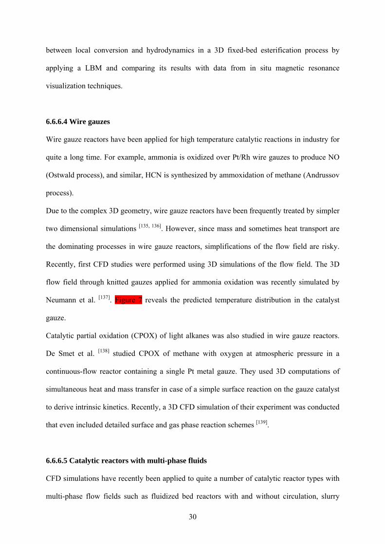
Neumann et al. [137]. Figure 7 reveals the predicted temperature distribution in the catalyst
gauze.
Catalytic partial oxidation (CPOX) of light alkanes was also studied in wire gauze reactors.
De Smet et al. [138] studied CPOX of methane with oxygen at atmospheric pressure in a
continuous-flow reactor containing a single Pt metal gauze. They used 3D computations of
simultaneous heat and mass transfer in case of a simple surface reaction on the gauze catalyst
to derive intrinsic kinetics. Recently, a 3D CFD simulation of their experiment was conducted
that even included detailed surface and gas phase reaction schemes [139].
6.6.6.5 Catalytic reactors with multi-phase fluids
CFD simulations have recently been applied to quite a number of catalytic reactor types with
multi-phase flow fields such as fluidized bed reactors with and without circulation, slurry

31
reactors, trickle-bed reactors, membrane reactors, electro-catalytic devices (e.g. fuel cells),
and reactive distillation devices. These multi-phase reactors are of multi-scale structure, i.e.
single particles, particle clusters/bubbles and reactor vessel, and of multiple physics, i.e.
hydrodynamics, heat and mass transfer, and reaction kinetics. The formation of complex
structures/patterns in each regime is a result of a compromise between dominant mechanisms
at multiple scales. Coupling of hydrodynamics, heat and mass transfer, and reaction kinetics
takes place at molecular and particle levels where conductive and convective transfer and
diffusion within the internal pores of the catalyst are accompanied by the adsorption, surface
reaction and desorption of reactant and product on the surface. Even though this complexity is
challenging for CFD simulations, computations are a promising tool to achieve a better
understanding of multi-phase reactors.
A detailed description of the fundamentals and modeling attempts of these multi-phase
reactors is beyond the scope of this Chapter. Instead, an example may serve as illustration of
the potential of CFD simulations of reactors with multi-phase flow fields: The CFD code
FLUENT was applied to study the catalytic decomposition of ozone (O3) by sand particles
impregnated with iron oxide in a fluidized bed, where ozone enters the bed in a uniform flow
from the bottom [92]. As it passes through the bed, O3 interacts with the catalyst and is
converted to molecular oxygen. Figure 8 shows the gas volume fraction in the bed after one
second of operation (red corresponding to 100% gas). It is observed that small bubbles gather
together into larger bubbles and create a desired hydrodynamic state for optimum conversion.
CFD simulations have recently been applied to far more catalytically reactive systems than
described so far. Here, only references to some of the literature can be given: poly electrolyte
membrane (PEM) [140, 141] and solid oxide (SOFC) [142, 143] fuel cells, fibrous active materials
[144, 145], gas-liquid-solid reactors [146], monolithic loop-reactors [147].

32
6.6.7 Summary and outlook
From a reaction engineering perspective, computational fluid dynamics simulations have been
matured to a powerful tool for understanding mass and heat transport in catalytic reactors.
Initially, CFD calculations focused on a better understanding of mixing, mass transfer to
enhance reaction rates, diffusion in porous media and heat transfer. Over the last ten years, the
flow field and heat transport models have also been coupled with models for heterogeneous
chemical reactions. So far, most of these models are based on the mean field approximation,
in which the local state of the surface is described by its coverage with adsorbed species
averaged on a microscopic scale. The currently increasing research activities on surface
reactions at practical conditions will certainly boost the application of CFD codes that
combine fluid flow and chemistry. New insights into the complexity of heterogeneous
catalysis, however, will also reveal the demand for more sophisticated chemistry models.
Their implementation into CFD simulations will then even require more sophisticated
numerical algorithms and computer hardware. Hence, CFD simulations of reactive systems
will remain a very active field and the implementation of more adequate and complex models
will continue.
The simulation results will always remain a reflection of the models and physical parameters
applied. The careful choice of the sub models (geometry, turbulence, diffusion, species, and
reactions involved, etc.) and the physical parameters (inlet and boundary conditions,
conductivity, permeability, viscosity, etc.) is a precondition for reliable simulation results.
Therefore, only the use of appropriate models and parameters, which describe all significant
processes in the reactor, can lead to reliable results. Furthermore, numerical algorithms never
give the accurate solution of the model equations but only an approximated solution. Hence,
error estimation is needed. Having these crucial issues in mind, CFD can really serve as
powerful tool in understanding the behavior in catalytic reactors and in supporting the design
and optimization of reactors and processes.

33
Acknowledgment
The author would like to thank J. Warnatz (University of Heidelberg), R.J. Kee (Colorado
School of Mines), S. Tischer, V.M. Janardhanan, and H.-H. Carstensen (all University of
Karlsruhe) for very stimulating discussions on modeling and simulation of chemical reactors.

34
6.6.8 References [1] Technology Vision 2020: The U.S. Chemical Industry, Report published by The
American Chemical Society, American Institute of Chemical Engineers, The Chemical Manufactures Association, The Council for Chemical Research, The Synthetic Organic Chemical Manufactures Association, 1996.
[2] R. J. Kee, M. E. Coltrin, P. Glarborg, Chemically Reacting Flow, John Wiley & Sons, Hoboken, New Jersey, 2003, 929 pp.
[3] R. B. Bird, W. E. Stewart, E. N. Lightfoot, Transport Phenomena, 2nd ed., John Wiley & Sons, Inc., New York, 2001, 912 pp.
[4] S. V. Patankar, Numerical Heat Transfer and Fluid Flow, McGraw-Hill, New York, 1980, 197 pp.
[5] J. Warnatz, R. W. Dibble, U. Maas, Combustion, Physical and Chemical Fundamentals, Modeling and Simulation, Experiments, Pollutant Formation, Springer-Verlag, New York, 1996, 299 pp.
[6] R. E. Hayes, S. T. Kolaczkowski, Introduction to Catalytic Combustion, Gordon and Breach Science Publ., Amsterdam, 1997, 690 pp.
[7] J. O. Hirschfelder, C. F. Curtiss, R. B. Bird, Molecular Theory of Gases and Liquids, rev. ed., Wiley, New York, 1964, 1280 pp.
[8] R. J. Kee, G. Dixon-Lewis, J. Warnatz, M. E. Coltrin, J. A. Miller, A Fortran Computer Code Package for the Evaluation of Gas-Phase Multicomponent Transport Properties, SAND86-8246, Sandia National Laboratories, 1986.
[9] M. W. Chase Jr., C. A. Davis, J. R. Downey Jr., D. J. Frurip, R. A. McDonald, A. N. Syverud, Journal of Physical and Chemical Reference Data 1985, 14, 1.
[10] R. J. Kee, F. M. Rupley, J. A. Miller, The Chemkin Thermodynamic Database, SAND87-8215, Sandia National Laboratories, Livermore, 1987.
[11] A. Burcat, in Combustion chemistry (Ed.: W. C. Gardiner), Springer, New York, 1984, p. 455.
[12] S. W. Benson, Thermochemical Kinetics, John Wiley & Sons, New York, 1976, 336 pp.
[13] P. A. Libby, F. A. Williams, Turbulent Reactive Flow, Academic Press, London, 1994, 647.
[14] S. B. Pope, Progress in Energy and Combustion Science 1985, 11, 119. [15] C. Appel, J. Mantzaras, R. Schaeren, R. Bombach, A. Inauen, Combustion and Flame
2005, 140, 70. [16] J. Mantzaras, C. Appel, P. Benz, U. Dogwiler, Catalysis Today 2000, 59, 3. [17] B. E. Launder, D. B. Spalding, Lectures in mathematical models of turbulence,
Academic Press, London/New York, 1972, 169 pp. [18] E. Gutheil, H. Bockhorn, Physicochemical Hydrodynamics 1987, 9, 525. [19] A. Beretta, P. Forzatti, E. Ranzi, Journal of Catalysis 1999, 184, 469. [20] A. Beretta, P. Forzatti, Journal of Catalysis 2001, 200, 45. [21] A. Beretta, E. Ranzi, P. Forzatti, Chemical Engineering Science 2001, 56, 779. [22] D. K. Zerkle, M. D. Allendorf, M. Wolf, O. Deutschmann, Journal of Catalysis 2000,
196, 18. [23] R. Subramanian, L. D. Schmidt, Angewandte Chemie-International Edition 2005, 44,
302. [24] J. J. Krummenacher, L. D. Schmidt, Journal of Catalysis 2004, 222, 429. [25] L. D. Schmidt, J. Siddall, M. Bearden, American Institute of Chemical Engineering
Journal 2000, 46, 1492. [26] F. Donsi, K. A. Williams, L. D. Schmidt, Industrial & Engineering Chemistry
Research 2005, 44, 3453.

35
[27] U. Maas, S. Pope, Combustion and Flame 1992, 88, 239. [28] X. Yan, U. Maas, Proceedings of the Combustion Institute 2000, 28, 1615. [29] R. G. Susnow, A. M. Dean, W. H. Green, P. Peczak, L. Broadbelt, Journal of Physical
Chemistry A 1997, 101, 3731. [30] M. E. Coltrin, R. J. Kee, F. M. Rupley, SURFACE CHEMKIN (Version 4.0): A
Fortran Package for Analyzing Heterogeneous Chemical Kinetics at a Solid-Surface - Gas-Phase Interface, SAND91-8003B, Sandia National Laboratories, 1991.
[31] O. Deutschmann, R. Schmidt, F. Behrendt, J. Warnatz, Proceedings of the Combustion Institute 1996, 26, 1747.
[32] L. L. Raja, R. J. Kee, L. R. Petzold, Proceedings of the Combustion Institute 1998, 27, 2249.
[33] D. Papadias, L. Edsberg, P. H. Björnbom, Catalysis Today 2000, 60, 11. [34] M. Baerns, H. Hofmann, A. Renken, Chemische Reaktionstechnik, Georg Thieme
Verlag, Stuttgart, New York, 1992. [35] H. Motz, H. Wise, Journal of Chemical Physics 1960, 32, 1893. [36] O. R. Inderwildi, D. Lebiedz, O. Deutschmann, J. Warnatz, Journal of Chemical
Physics 2005, 122. [37] A. Heyden, B. Peters, A. T. Bell, F. J. Keil, Journal of Physical Chemistry B 2005,
109, 4801. [38] W. R. Williams, C. M. Marks, L. D. Schmidt, Journal of Physical Chemistry 1992, 96,
5922. [39] B. Hellsing, B. Kasemo, V. P. Zhdanov, Journal of Catalysis 1991, 132, 210. [40] J. Warnatz, Proceedings of the Combustion Institute 1992, 24, 553. [41] M. Rinnemo, O. Deutschmann, F. Behrendt, B. Kasemo, Combustion and Flame
1997, 111, 312. [42] G. Veser, Chemical Engineering Science 2001, 56, 1265. [43] P.-A. Bui, D. G. Vlachos, P. R. Westmoreland, Industrial & Engineering Chemistry
Research 1997, 36, 2558. [44] J. C. G. Andrae, P. H. Björnbom, American Institute of Chemical Engineering Journal
2000, 46, 1454. [45] J. Mai, W. von Niessen, A. Blumen, Journal of Chemical Physics 1990, 93, 3685. [46] V. P. Zhdanov, B. Kasemo, Applied Surface Science 1994, 74, 147. [47] P. Aghalayam, Y. K. Park, D. G. Vlachos, Proceedings of the Combustion Institute
2000, 28, 1331. [48] G. Veser, J. Frauhammer, L. D. Schmidt, G. Eigenberger, in Dynamics of Surfaces
and Reaction Kinetics in Heterogeneous Catalysis, G. F. Froment, K. C. Waugh (Eds.), Studies in Surface Science and Catalysis 109, 1997, p. 273.
[49] P.-A. Bui, D. G. Vlachos, P. R. Westmoreland, Surface Science 1997, 386, L1029. [50] U. Dogwiler, P. Benz, J. Mantzaras, Combustion and Flame 1999, 116, 243. [51] P. Aghalayam, Y. K. Park, N. Fernandes, V. Papavassiliou, A. B. Mhadeshwar, D. G.
Vlachos, Journal of Catalysis 2003, 213, 23. [52] D. A. Hickman, L. D. Schmidt, American Institute of Chemical Engineering Journal
1993, 39, 1164. [53] M. Huff, L. D. Schmidt, Journal of Physical Chemistry 1993, 97, 11815. [54] M. C. Huff, I. P. Androulakis, J. H. Sinfelt, S. C. Reyes, Journal of Catalysis 2000,
191, 46. [55] R. Schwiedernoch, S. Tischer, C. Correa, O. Deutschmann, Chemical Engineering
Science 2003, 58, 633. [56] D. Chatterjee, O. Deutschmann, J. Warnatz, Faraday Discussions 2001, 119, 371. [57] B. Ruf, F. Behrendt, O. Deutschmann, J. Warnatz, Surface Science 1996, 352, 602. [58] S. J. Harris, D. G. Goodwin, Journal of Physical Chemistry 1993, 97, 23.

36
[59] S. Romet, M. F. Couturier, T. K. Whidden, Journal of the Electrochemical Society 2001, 148, G82.
[60] C. D. Scott, A. Povitsky, C. Dateo, T. Gokcen, P. A. Willis, R. E. Smalley, Journal of Nanoscience and Nanotechnology 2003, 3, 63.
[61] A. B. Mhadeshwar, H. Wang, D. G. Vlachos, Journal of Physical Chemistry B 2003, 107, 12721.
[62] R. Kissel-Osterrieder, F. Behrendt, J. Warnatz, U. Metka, H. R. Volpp, J. Wolfrum, Proceedings of the Combustion Institute 2000, 28, 1341.
[63] J. A. Dumesic, D. F. Rudd, L. M. Aparicio, J. E. Rekoske, A. A. Trevino, The Microkinetics of Heterogeneous Catalysis, American Chemical Society, Washington, DC, 1993, 316 pp.
[64] S. J. Lombardo, A. T. Bell, Surface Science 1988, 206, 101. [65] R. Kissel-Osterrieder, F. Behrendt, J. Warnatz, Proceedings of the Combustion
Institute 1998, 27, 2267. [66] T. Horstmann, H. Leuckel, B. Maurer, U. Maas, Process Safety Progress 2001, 20,
215. [67] H. P. A. Calis, J. Nijenhuis, B. C. Paikert, F. M. Dautzenberg, C. M. van den Bleek,
Chemical Engineering Science 2001, 56, 1713. [68] C. Appel, J. Mantzaras, R. Schaeren, R. Bombach, B. Kaeppeli, A. Inauen,
Proceedings of the Combustion Institute 2003, 29, 1031. [69] M. Reinke, J. Mantzaras, R. Schaeren, R. Bombach, W. Kreutner, A. Inauen,
Proceedings of the Combustion Institute 2002, 29, 1021. [70] U. Dogwiler, P. Benz, J. Mantzaras, Combustion and Flame 1999, 116, 243. [71] J. Mantzaras, C. Appel, P. Benz, Proceedings of the Combustion Institute 2000, 28,
1349. [72] J. Mantzaras, C. Appel, Combustion and Flame 2002, 130, 336. [73] M. Reinke, J. Mantzaras, R. Schaeren, R. Bombach, A. Inauen, S. Schenker,
Combustion and Flame 2004, 136, 217. [74] R. Aris, The Mathematical Theory of Diffusion and Reaction in Permeable Catalysts,
Clarendon Press, Oxford, 1975, 232 pp. [75] F. Keil, Diffusion und Chemische Reaktionen in der Gas-Feststoff-Katalyse, Springer-
Verlag, Berlin, 1999, 340 pp. [76] O. Bey, G. Eigenberger, Chemical Engineering Science 1997, 52, 1365. [77] M. Giese, K. Rottschafer, D. Vortmeyer, American Institute of Chemical Engineering
Journal 1998, 44, 484. [78] M. Winterberg, E. Tsotsas, A. Krischke, D. Vortmeyer, Chemical Engineering Science
2000, 55, 967. [79] E. Mason, A. Malinauskas, Gas Transport in Porous Media: The Dusty-Gas Model,
American Elsevier, New York, 1983, 194 pp. [80] P. Kerkhof, M. A. M. Geboers, American Institute of Chemical Engineering Journal
2005, 51, 79. [81] P. Kerkhof, Chemical Engineering Journal 1996, 64, 319. [82] V. V. Ranade, Computational Flow Modeling for Chemical Reactor Engineering,
Acadamic Press, San Diego, CA, 2002, 600 pp. [83] R. E. Hayes, S. T. Kolaczkowski, W. J. Thomas, Computers & Chemical Engineering
1997, 16, 654. [84] D. S. Burnett, Finite Element Analysis, Addison-Wesley Publ. Comp., Reading, 1987. [85] S. Succi, The Lattice Boltzmann Equation for Fluid Dynamics and Beyond, Oxford
University Press, 2001, 368 pp. [86] S. P. Sullivan, F. M. Sani, M. L. Johns, L. F. Gladden, Chemical Engineering Science
2005, 60, 3405.
37
[87] H. Freund, T. Zeiser, F. Huber, E. Klemm, G. Brenner, F. Durst, G. Emig, Chemical Engineering Science 2003, 58, 903.
[88] T. Zeiser, P. Lammers, E. Klemm, Y. W. Li, J. Bernsdorf, G. Brenner, Chemical Engineering Science 2001, 56, 1697.
[89] R. J. Kee, F. M. Rupley, J. A. Miller, M. E. Coltrin, J. F. Grcar, E. Meeks, H. K. Moffat, A. E. Lutz, G. Dixon-Lewis, M. D. Smooke, J. Warnatz, G. H. Evans, R. S. Larson, R. E. Mitchell, L. R. Petzold, W. C. Reynolds, M. Caracotsios, W. E. Stewart, P. Glarborg, C. Wang, O. Adigun, CHEMKIN, 3.6 ed., Reaction Design, Inc., www.chemkin.com, San Diego, 2000.
[90] D. G. Goodwin, CANTERA. An open-source, extensible software suite for CVD process simulation, www.cantera.org, 2003.
[91] O. Deutschmann, S. Tischer, C. Correa, D. Chatterjee, S. Kleditzsch, V. M. Janardhanan, DETCHEM software package, 2.0 ed., www.detchem.com, Karlsruhe, 2004.
[92] Fluent, Fluent Incorporated, www.fluent.com, Lebanon, NH, 2005. [93] CD-adapco, London Office, 200 Shepherds Bush Road, London, W6 7NY, United
Kingdom, www.cd-adapco.com. [94] FIRE, AVL LIST GmbH, www.avl.com, Graz, Austria, 2005. [95] CFD-AC+, CFD Research Corporation, www.cfdrc.com, Huntsville, AL, 2005. [96] CFX, www-waterloo.ansys.com, 2005. [97] J. Shadid, S. Hutchinson, G. Hennigan, H. Moffat, K. Devine, A. G. Salinger, Parallel
Computing 1997, 23, 1307. [98] FEMLAB, www.comsol.com, 2005. [99] K. E. Brenan, S. L. Campbell, L. R. Petzold, Numerical Solution of Initial-Value
Problems in Differential-Algebraic Equations, 2nd ed., SIAM, Philadelphia, PA, 1996, 256 pp.
[100] A. C. Hindmarsh, in Scientific Computing (Ed.: R. S. Stepleman), North Holland Publishing Co., Amsterdam, 1983, pp. 55.
[101] P. Deuflhardt, E. Hairer, J. Zugk, Numerische Mathematik 1987, 51, 501. [102] P. Deuflhard, U. Nowak, Progress in Scientific Computing 1987, 7, 37. [103] P. N. Brown, G. D. Byrne, A. C. Hindmarsh, SIAM Journal on Scientific and
Statistical Computing 1989, 10, 1038. [104] U. M. Ascher, L. R. Petzold, Computer Methods for Ordinary Differential Equations
and Differential-Algebraic Equations, SIAM, Philadelphia, PA, 1998, 314 pp. [105] R. E. Hayes, B. Liu, M. Votsmeier, Chemical Engineering Science 2005, 60, 2037. [106] R. E. Hayes, B. Liu, R. Moxom, M. Votsmeier, Chemical Engineering Science 2004,
59, 3169. [107] O. Deutschmann, R. Schwiedernoch, L. Maier, D. Chatterjee, in Natural Gas
Conversion VI, E. Iglesia, J. J. Spivey, T. H. Fleisch (Eds.), Studies in Surface Science and Catalysis, Vol. 136, Elsevier, Amsterdam, 2001, p. 251.
[108] H. Schlichting, K. Gersten, Boundary-Layer Theory, 8th ed., Springer-Verlag, Heidelberg, 1999, 801 pp.
[109] L. L. Raja, R. J. Kee, O. Deutschmann, J. Warnatz, L. D. Schmidt, Catalysis Today 2000, 59, 47.
[110] R. E. Hayes, S. T. Kolaczkowski, Catalysis Today 1999, 47, 295. [111] G. Veser, J. Frauhammer, Chemical Engineering Science 2000, 55, 2271. [112] R. E. Hayes, S. T. Kolaczkowski, W. J. Thomas, Computers & Chemical Engineering
1992, 16, 645. [113] R. Wanker, H. Raupenstrauch, G. Staudinger, Chemical Engineering Science 2000,
55, 4709.

38
[114] R. Wanker, M. Berg, H. Raupenstrauch, G. Staudinger, Chemical Engineering & Technology 2000, 23, 535.
[115] S. T. Kolaczkowski, Catalysis Today 1999, 47, 209. [116] S. Mazumder, D. Sengupta, Combustion and Flame 2002, 131, 85. [117] R. Jahn, D. Snita, M. Kubicek, M. Marek, Catalysis Today 1997, 38, 39. [118] G. C. Koltsakis, P. A. Konstantinidis, A. M. Stamatelos, Applied Catalysis B:
Environmental 1997, 12, 161. [119] S. Tischer, C. Correa, O. Deutschmann, Catalysis Today 2001, 69, 57. [120] S. Tischer, O. Deutschmann, Catalysis Today 2005, 105, 407. [121] S. S. E. H. Elnashaie, S. S. Elnashaie, Modelling, Simulation and Optimization of
Industrial Fixed Bed Catalytic Reactors, G+B Gordon and Breach, Amsterdam, 1995. [122] A. G. Dixon, M. Nijemeisland, Industrial & Engineering Chemistry Research 2001,
40, 5246. [123] M. Bizzi, G. Saracco, R. Schwiedernoch, O. Deutschmann, AIChE Journal 2004, 50,
1289. [124] M. Bauer, R. Adler, Chemical Engineering & Technology 2003, 26, 545. [125] J. P. Sorensen, W. E. Stewart, Chemical Engineering Science 1974, 29, 827. [126] M. T. Dalman, J. H. Merkin, C. McGreavy, Computers & Fluids 1986, 14, 267. [127] B. Lloyd, R. Boehm, Numerical Heat Transfer Part A - Applications 1994, 26, 237. [128] K. Debus, H. Nirschl, A. Delgado, V. Denk, Chemie Ingenieur Technik 1998, 70, 415. [129] S. A. Logtenberg, M. Nijemeisland, A. G. Dixon, Chemical Engineering Science
1999, 54, 2433. [130] C. F. Petre, F. Larachi, I. Iliuta, B. P. A. Grandjean, Chemical Engineering Science
2003, 58, 163. [131] M. Nijemeisland, A. G. Dixon, American Institute of Chemical Engineering Journal
2004, 50, 906. [132] V. Yakhot, S. A. Orszag, Physical Review Letters 1986, 57, 1722. [133] B. E. Laudner, D. B. Spalding, Computer Methods in Applied Mathematics and
Engineering 1974, 3, 169. [134] E. H. L. Yuen, A. J. Sederman, F. Sani, P. Alexander, L. F. Gladden, Chemical
Engineering Science 2003, 58, 613. [135] V. P. Zakharov, I. A. Zolotarskii, V. A. Kuzmin, Chemical Engineering Journal 2003,
91, 249. [136] R. P. O´Connor, L. D. Schmidt, O. Deutschmann, American Institute of Chemical
Engineering Journal 2002, 48, 1241. [137] J. Neumann, H. Golitzer, A. Heywood, I. Ticu, Revista De Chimie 2002, 53, 721. [138] C. R. H. de Smet, M. H. J. M. de Croon, R. J. Berger, G. B. Marin, J. C. Schouten,
Applied Catalysis A: General 1999, 187, 33. [139] R. Quiceno, J. Pérez-Ramírez, J. Warnatz, O. Deutschmann, Applied Catalysis A:
General 2006, in press. [140] B. R. Sivertsen, N. Djilali, Journal of Power Sources 2005, 141, 65. [141] N. P. Siegel, M. W. Ellis, D. J. Nelson, M. R. von Spakovsky, Journal of Power
Sources 2003, 115, 81. [142] B. Morel, J. Laurencin, Y. Bultel, F. Lefebvre-Joud, Journal of the Electrochemical
Society 2005, 152, A1382. [143] H. Zhu, R. J. Kee, D. G. Goodwin, V. M. Janardhanan, O. Deutschmann, J.
Electrochem. Soc. 2005, 152, A2427. [144] O. V. Chub, E. S. Borisova, O. P. Klenov, A. S. Noskov, A. Matveev, I. V. Koptyug,
Catalysis Today 2005, 105, 680. [145] J. De Greef, G. Desmet, G. Baron, Catalysis Today 2005, 105, 331. [146] S. Roy, A. K. Heibel, W. Liu, T. Boger, Chemical Engineering Science 2004, 59, 957.

39
[147] T. Boger, S. Roy, A. K. Heibel, O. Borchers, Catalysis Today 2003, 79, 441.

40
FIGURES
Figure 1: Catalytic combustion monolith and physical and chemical process occurring in the
single monolith channel.
Figure 2: Survey of the methodology of the development of a surface reaction mechanism.

41
Figure 3: LIF measurements (a) and predictions (b-d) of OH radical profiles in the transition
from heterogeneous to homogeneous oxidation of methane in a Pt coated channel at 6 bar;
three different wide-spread reaction schemes were evaluated revealing the reliability of
scheme (b) and deficiencies of the schemes (c) and (d). The Figures were taken from Reinke
et al. [69].
Figure 4: Structure of the computer code DETCHEMMONOLITH [91].
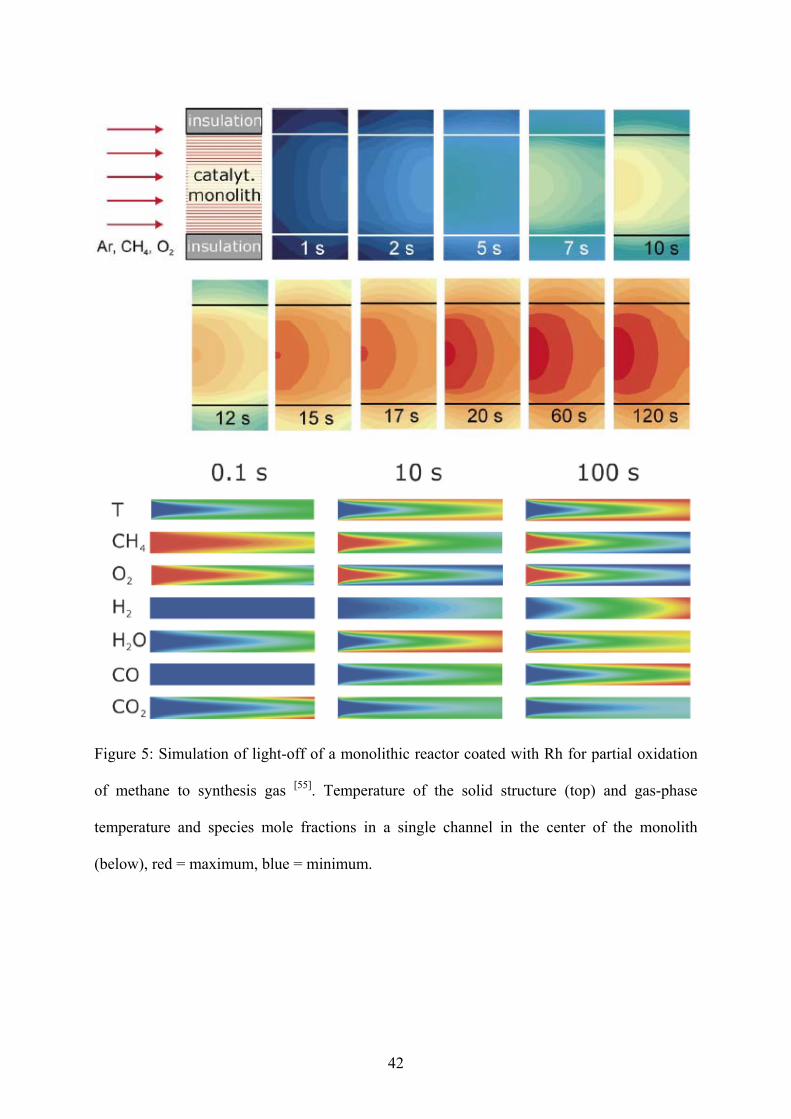
42
Figure 5: Simulation of light-off of a monolithic reactor coated with Rh for partial oxidation
of methane to synthesis gas [55]. Temperature of the solid structure (top) and gas-phase
temperature and species mole fractions in a single channel in the center of the monolith
(below), red = maximum, blue = minimum.

43
Figure 6: Computational grid structure and computed temperature profile in a vertical plane of
a CFD simulation of a fixed bed reactor, taken from Nijemeisland and Dixon [131].
Figure 7: Computed temperature profile in a MULTINIT® catalyst gauze (flow direction from
left to right), taken from Neumann et al. [137].

44
Figure 8: Computed gas volume fraction in the fluidized bed after 1 second of operation (red
corresponding to 100% gas), taken from [92] (Example X241).