chapter03-1mips-isa.pdf
TRANSCRIPT

BKTP.HCM
2014
dce
COMPUTER ARCHITECTURECSE Fall 2014
Faculty of Computer Science and Engineering
Department of Computer Engineering
Vo Tan Phuong
http://www.cse.hcmut.edu.vn/~vtphuong

2014
dce
2Computer Architecture – Chapter 3.1 © Fall 2014, CS
Chapter 3
MIPS Instruction Set Architecture

2014
dce
3Computer Architecture – Chapter 3.1 © Fall 2014, CS
Presentation Outline• Instruction Set Architecture
• Overview of the MIPS Architecture
• R-Type Arithmetic, Logical, and Shift Instructions
• I-Type Format and Immediate Constants
• Jump and Branch Instructions
• Translating If Statements and Boolean Expressions
• Load and Store Instructions
• Translating Loops and Traversing Arrays
• Addressing Modes

2014
dce
4Computer Architecture – Chapter 3.1 © Fall 2014, CS
Instruction Set Architecture (ISA)
• Critical Interface between hardware and software
• An ISA includes the following …
– Instructions and Instruction Formats
– Data Types, Encodings, and Representations
– Programmable Storage: Registers and Memory
– Addressing Modes: to address Instructions and Data
– Handling Exceptional Conditions (like division by zero)
• Examples (Versions) Introduced in
– Intel (8086, 80386, Pentium, ...) 1978
– MIPS (MIPS I, II, III, IV, V) 1986
– PowerPC (601, 604, …) 1993

2014
dce
5Computer Architecture – Chapter 3.1 © Fall 2014, CS
Accumulator architecture
Example code: a = b+c;
load b; // accumulator is implicit operand
add c;
store a;
Accumulator
ALU Memory
registersaddress
latch
latch

2014
dce
6Computer Architecture – Chapter 3.1 © Fall 2014, CS
Stack architecture
Example code: a = b+c;
push b;
push c;
add;
pop a;
b
b
c b+c
push b push c add pop a
stack:
ALU Memory
stack
stack pt
latch
latch
latch

2014
dce
7Computer Architecture – Chapter 3.1 © Fall 2014, CS
Other architecture styles
Stack
Architecture
Accumulator
Architecture
Register-
Memory
Memory-
Memory
Register
(load-store)
Push A Load A Load r1,A Add C,B,A Load r1,A
Push B Add B Add r1,B Load r2,B
Add Store C Store C,r1 Add r3,r1,r2
Pop C Store C,r3
Let's look at the code for C = A + B
Your turn: C = A + B + 5 with Stack and Accumulator
architecture?

2014
dce
8Computer Architecture – Chapter 3.1 © Fall 2014, CS
Other architecture styles• Accumulator architecture
– one operand (in register or memory), accumulator almost always implicitly used
• Stack– zero operand: all operands implicit (on TOS)
• Register (load store)– three operands, all in registers
– loads and stores are the only instructions accessing memory (i.e. with a memory (indirect) addressing mode
• Register-Memory– two operands, one in memory
• Memory-Memory– three operands, may be all in memory

2014
dce
9Computer Architecture – Chapter 3.1 © Fall 2014, CS
Instructions• Instructions are the language of the machine
• We will study the MIPS instruction set architecture
– Known as Reduced Instruction Set Computer (RISC)
– Elegant and relatively simple design
– Similar to RISC architectures developed in mid-1980’s and 90’s
– Very popular, used in many products
• Silicon Graphics, ATI, Cisco, Sony, etc.
– Comes next in sales after Intel IA-32 processors
• Almost 100 million MIPS processors sold in 2002
(and increasing)
• Alternative design: Intel IA-32
– Known as Complex Instruction Set Computer (CISC)

2014
dce
10Computer Architecture – Chapter 3.1 © Fall 2014, CS
Next . . .
• Instruction Set Architecture
• Overview of the MIPS Architecture
• R-Type Arithmetic, Logical, and Shift Instructions
• I-Type Format and Immediate Constants
• Jump and Branch Instructions
• Translating If Statements and Boolean Expressions
• Load and Store Instructions
• Translating Loops and Traversing Arrays
• Addressing Modes
2014
dce
11Computer Architecture – Chapter 3.1 © Fall 2014, CS
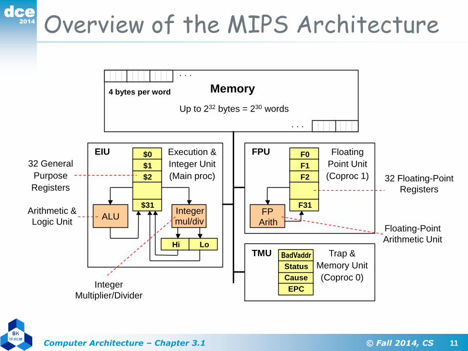
Overview of the MIPS Architecture
Memory
Up to 232 bytes = 230 words
4 bytes per word
$0
$1
$2
$31
Hi Lo
ALU
F0
F1
F2
F31FP
Arith
EPC
Cause
BadVaddr
Status
EIU FPU
TMU
Execution &
Integer Unit
(Main proc)
Floating
Point Unit
(Coproc 1)
Trap &
Memory Unit
(Coproc 0)
. . .
. . .
Integermul/div
Arithmetic &
Logic Unit
32 General
Purpose
Registers
Integer
Multiplier/Divider
32 Floating-Point
Registers
Floating-Point
Arithmetic Unit

2014
dce
12Computer Architecture – Chapter 3.1 © Fall 2014, CS
MIPS General-Purpose Registers
• 32 General Purpose Registers (GPRs)
– Assembler uses the dollar notation to name registers
• $0 is register 0, $1 is register 1, …, and $31 is
register 31
– All registers are 32-bit wide in MIPS32
– Register $0 is always zero
• Any value written to $0 is discarded
• Software conventions
– There are many registers (32)
– Software defines names to all registers
• To standardize their use in programs
– Example: $8 - $15 are called $t0 - $t7
• Used for temporary values
$0 = $zero
$1 = $at
$2 = $v0
$3 = $v1
$4 = $a0
$5 = $a1
$6 = $a2
$7 = $a3
$8 = $t0
$9 = $t1
$10 = $t2
$11 = $t3
$12 = $t4
$13 = $t5
$14 = $t6
$15 = $t7
$16 = $s0
$17 = $s1
$18 = $s2
$19 = $s3
$20 = $s4
$21 = $s5
$22 = $s6
$23 = $s7
$24 = $t8
$25 = $t9
$26 = $k0
$27 = $k1
$28 = $gp
$29 = $sp
$30 = $fp
$31 = $ra
2014
dce
13Computer Architecture – Chapter 3.1 © Fall 2014, CS
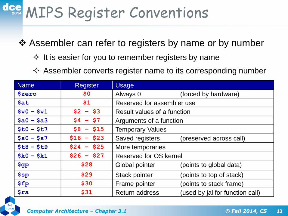
MIPS Register Conventions
Name Register Usage
$zero $0 Always 0 (forced by hardware)
$at $1 Reserved for assembler use
$v0 – $v1 $2 – $3 Result values of a function
$a0 – $a3 $4 – $7 Arguments of a function
$t0 – $t7 $8 – $15 Temporary Values
$s0 – $s7 $16 – $23 Saved registers (preserved across call)
$t8 – $t9 $24 – $25 More temporaries
$k0 – $k1 $26 – $27 Reserved for OS kernel
$gp $28 Global pointer (points to global data)
$sp $29 Stack pointer (points to top of stack)
$fp $30 Frame pointer (points to stack frame)
$ra $31 Return address (used by jal for function call)
Assembler can refer to registers by name or by number
It is easier for you to remember registers by name
Assembler converts register name to its corresponding number

2014
dce
14Computer Architecture – Chapter 3.1 © Fall 2014, CS
Instruction Formats
• All instructions are 32-bit wide, Three instruction formats:
• Register (R-Type)
– Register-to-register instructions
– Op: operation code specifies the format of the instruction
• Immediate (I-Type)
– 16-bit immediate constant is part in the instruction
• Jump (J-Type)
– Used by jump instructions
Op6 Rs5 Rt5 Rd5 funct6sa5
Op6 Rs5 Rt5 immediate16
Op6 immediate26

2014
dce
15Computer Architecture – Chapter 3.1 © Fall 2014, CS
Instruction Categories
• Integer Arithmetic
– Arithmetic, logical, and shift instructions
• Data Transfer
– Load and store instructions that access memory
– Data movement and conversions
• Jump and Branch
– Flow-control instructions that alter the sequential sequence
• Floating Point Arithmetic
– Instructions that operate on floating-point registers
• Miscellaneous
– Instructions that transfer control to/from exception handlers
– Memory management instructions
2014
dce
16Computer Architecture – Chapter 3.1 © Fall 2014, CS
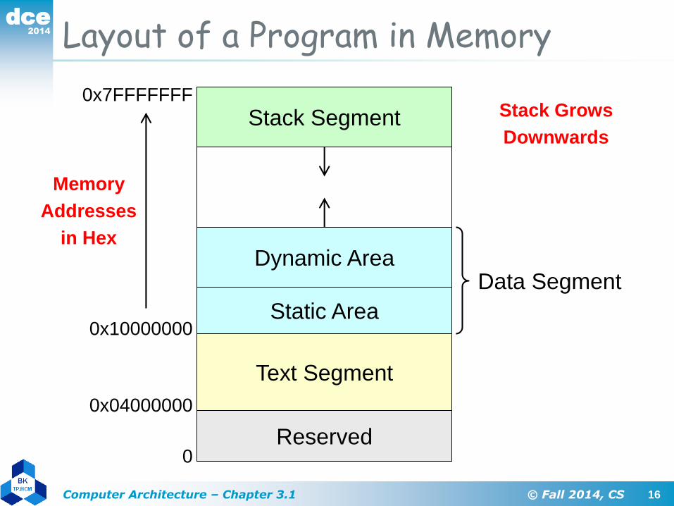
Layout of a Program in Memory
Stack Segment0x7FFFFFFF
Dynamic Area
Static Area
Text Segment
Reserved
0x04000000
0x10000000
0
Data Segment
Memory
Addresses
in Hex
Stack Grows
Downwards

2014
dce
17Computer Architecture – Chapter 3.1 © Fall 2014, CS
Next . . .
• Instruction Set Architecture
• Overview of the MIPS Architecture
• R-Type Arithmetic, Logical, and Shift Instructions
• I-Type Format and Immediate Constants
• Jump and Branch Instructions
• Translating If Statements and Boolean Expressions
• Load and Store Instructions
• Translating Loops and Traversing Arrays
• Addressing Modes
2014
dce
18Computer Architecture – Chapter 3.1 © Fall 2014, CS
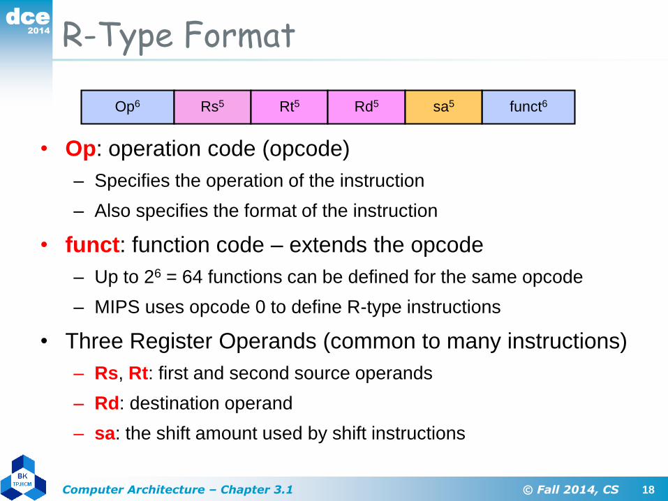
R-Type Format
• Op: operation code (opcode)
– Specifies the operation of the instruction
– Also specifies the format of the instruction
• funct: function code – extends the opcode
– Up to 26 = 64 functions can be defined for the same opcode
– MIPS uses opcode 0 to define R-type instructions
• Three Register Operands (common to many instructions)
– Rs, Rt: first and second source operands
– Rd: destination operand
– sa: the shift amount used by shift instructions
Op6 Rs5 Rt5 Rd5 funct6sa5
2014
dce
19Computer Architecture – Chapter 3.1 © Fall 2014, CS
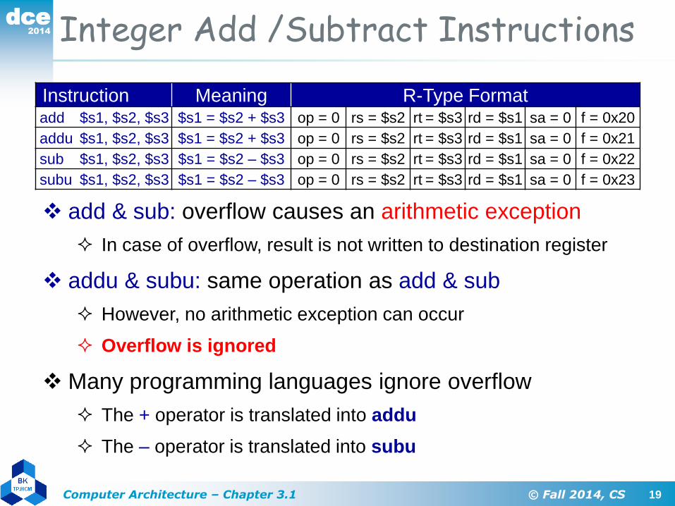
Integer Add /Subtract Instructions
Instruction Meaning R-Type Formatadd $s1, $s2, $s3 $s1 = $s2 + $s3 op = 0 rs = $s2 rt = $s3 rd = $s1 sa = 0 f = 0x20
addu $s1, $s2, $s3 $s1 = $s2 + $s3 op = 0 rs = $s2 rt = $s3 rd = $s1 sa = 0 f = 0x21
sub $s1, $s2, $s3 $s1 = $s2 – $s3 op = 0 rs = $s2 rt = $s3 rd = $s1 sa = 0 f = 0x22
subu $s1, $s2, $s3 $s1 = $s2 – $s3 op = 0 rs = $s2 rt = $s3 rd = $s1 sa = 0 f = 0x23
add & sub: overflow causes an arithmetic exception
In case of overflow, result is not written to destination register
addu & subu: same operation as add & sub
However, no arithmetic exception can occur
Overflow is ignored
Many programming languages ignore overflow
The + operator is translated into addu
The – operator is translated into subu

2014
dce
20Computer Architecture – Chapter 3.1 © Fall 2014, CS
Addition/Subtraction Example
• Consider the translation of: f = (g+h) – (i+j)
• Compiler allocates registers to variables
– Assume that f, g, h, i, and j are allocated registers $s0 thru $s4
– Called the saved registers: $s0 = $16, $s1 = $17, …, $s7 = $23
• Translation of: f = (g+h) – (i+j)addu $t0, $s1, $s2 # $t0 = g + h
addu $t1, $s3, $s4 # $t1 = i + j
subu $s0, $t0, $t1 # f = (g+h)–(i+j)
– Temporary results are stored in $t0 = $8 and $t1 = $9
• Translate: addu $t0,$s1,$s2 to binary code
• Solution:
000000
op
10001
rs = $s1
10010
rt = $s2
01000
rd = $t0
00000
sa
100001
func

2014
dce
21Computer Architecture – Chapter 3.1 © Fall 2014, CS
Logical Bitwise Operations
• Logical bitwise operations: and, or, xor, nor
• AND instruction is used to clear bits: x and 0 = 0
• OR instruction is used to set bits: x or 1 = 1
• XOR instruction is used to toggle bits: x xor 1 = not x
• NOR instruction can be used as a NOT, how?
– nor $s1,$s2,$s2 is equivalent to not $s1,$s2
x
0
0
1
1
y
0
1
0
1
x and y
0
0
0
1
x
0
0
1
1
y
0
1
0
1
x or y
0
1
1
1
x
0
0
1
1
y
0
1
0
1
x xor y
0
1
1
0
x
0
0
1
1
y
0
1
0
1
x nor y
1
0
0
0

2014
dce
22Computer Architecture – Chapter 3.1 © Fall 2014, CS
Logical Bitwise Instructions
Instruction Meaning R-Type Formatand $s1, $s2, $s3 $s1 = $s2 & $s3 op = 0 rs = $s2 rt = $s3 rd = $s1 sa = 0 f = 0x24
or $s1, $s2, $s3 $s1 = $s2 | $s3 op = 0 rs = $s2 rt = $s3 rd = $s1 sa = 0 f = 0x25
xor $s1, $s2, $s3 $s1 = $s2 ^ $s3 op = 0 rs = $s2 rt = $s3 rd = $s1 sa = 0 f = 0x26
nor $s1, $s2, $s3 $s1 = ~($s2|$s3) op = 0 rs = $s2 rt = $s3 rd = $s1 sa = 0 f = 0x27
Examples:
Assume $s1 = 0xabcd1234 and $s2 = 0xffff0000
and $s0,$s1,$s2 # $s0 = 0xabcd0000
or $s0,$s1,$s2 # $s0 = 0xffff1234
xor $s0,$s1,$s2 # $s0 = 0x54321234
nor $s0,$s1,$s2 # $s0 = 0x0000edcb
2014
dce
23Computer Architecture – Chapter 3.1 © Fall 2014, CS
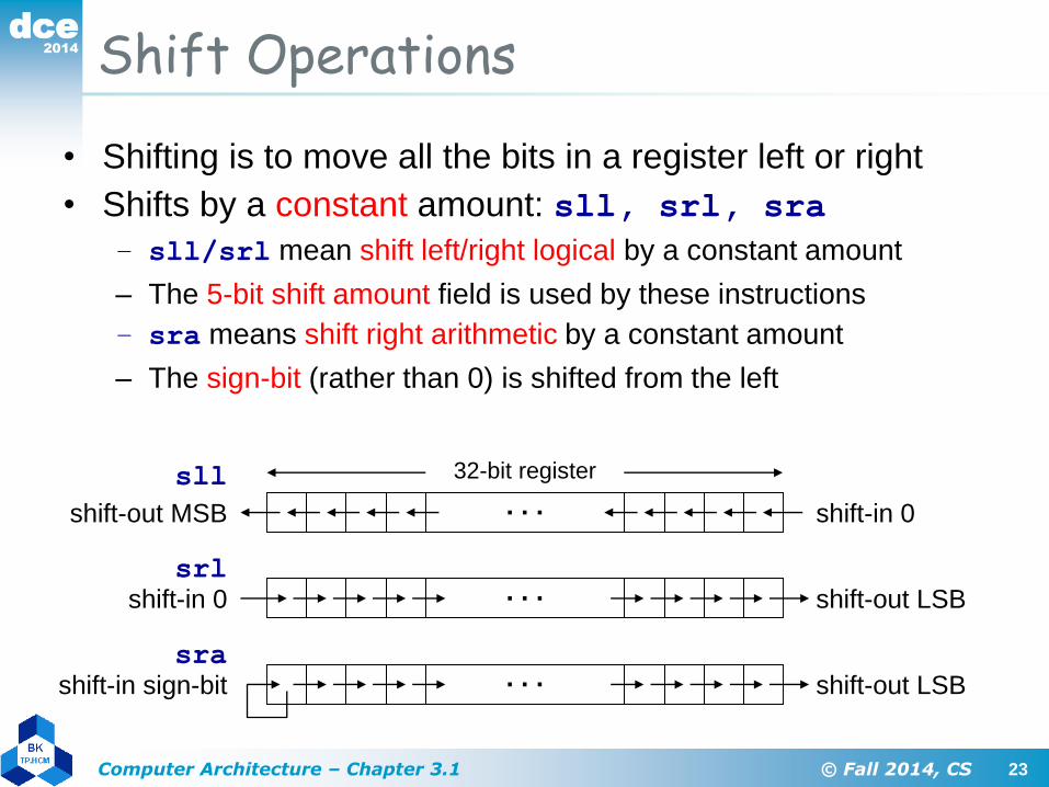
Shift Operations
• Shifting is to move all the bits in a register left or right
• Shifts by a constant amount: sll, srl, sra
– sll/srl mean shift left/right logical by a constant amount
– The 5-bit shift amount field is used by these instructions
– sra means shift right arithmetic by a constant amount
– The sign-bit (rather than 0) is shifted from the left
shift-in 0. . .shift-out MSB
sll 32-bit register
. . .shift-in 0 shift-out LSB
srl
. . .shift-in sign-bit shift-out LSB
sra

2014
dce
24Computer Architecture – Chapter 3.1 © Fall 2014, CS
$s1 = 0x0000abcd
$s1 = 0xcd123400
Shift Instructions
• Shifts by a variable amount: sllv, srlv, srav
– Same as sll, srl, sra, but a register is used for shift amount
• Examples: assume that $s2 = 0xabcd1234, $s3 = 16
Instruction Meaning R-Type Formatsll $s1,$s2,10 $s1 = $s2 << 10 op = 0 rs = 0 rt = $s2 rd = $s1 sa = 10 f = 0
srl $s1,$s2,10 $s1 = $s2>>>10 op = 0 rs = 0 rt = $s2 rd = $s1 sa = 10 f = 2
sra $s1, $s2, 10 $s1 = $s2 >> 10 op = 0 rs = 0 rt = $s2 rd = $s1 sa = 10 f = 3
sllv $s1,$s2,$s3 $s1 = $s2 << $s3 op = 0 rs = $s3 rt = $s2 rd = $s1 sa = 0 f = 4
srlv $s1,$s2,$s3 $s1 = $s2>>>$s3 op = 0 rs = $s3 rt = $s2 rd = $s1 sa = 0 f = 6
srav $s1,$s2,$s3 $s1 = $s2 >> $s3 op = 0 rs = $s3 rt = $s2 rd = $s1 sa = 0 f = 7
sll $s1,$s2,8
sra $s1,$s2,4 $s1 = 0xfabcd123
srlv $s1,$s2,$s3
rt=$s2=10010op=000000 rs=$s3=10011 rd=$s1=10001 sa=00000 f=000110
$s1 = $s2<<8
$s1 = $s2>>4
$s1 = $s2>>>$s3

2014
dce
25Computer Architecture – Chapter 3.1 © Fall 2014, CS
Binary Multiplication
• Shift-left (sll) instruction can perform multiplication
– When the multiplier is a power of 2
• You can factor any binary number into powers of 2
– Example: multiply $s1 by 36
• Factor 36 into (4 + 32) and use distributive
property of multiplication
– $s2 = $s1*36 = $s1*(4 + 32) = $s1*4 + $s1*32
sll $t0, $s1, 2 ; $t0 = $s1 * 4
sll $t1, $s1, 5 ; $t1 = $s1 * 32
addu $s2, $t0, $t1 ; $s2 = $s1 * 36

2014
dce
26Computer Architecture – Chapter 3.1 © Fall 2014, CS
Your Turn . . .
sll $t0, $s1, 1 ; $t0 = $s1 * 2
sll $t1, $s1, 3 ; $t1 = $s1 * 8
addu $s2, $t0, $t1 ; $s2 = $s1 * 10
sll $t0, $s1, 4 ; $t0 = $s1 * 16
addu $s2, $s2, $t0 ; $s2 = $s1 * 26
Multiply $s1 by 26, using shift and add instructions
Hint: 26 = 2 + 8 + 16
Multiply $s1 by 31, Hint: 31 = 32 – 1
sll $s2, $s1, 5 ; $s2 = $s1 * 32
subu $s2, $s2, $s1 ; $s2 = $s1 * 31

2014
dce
27Computer Architecture – Chapter 3.1 © Fall 2014, CS
Next . . .
• Instruction Set Architecture
• Overview of the MIPS Architecture
• R-Type Arithmetic, Logical, and Shift Instructions
• I-Type Format and Immediate Constants
• Jump and Branch Instructions
• Translating If Statements and Boolean Expressions
• Load and Store Instructions
• Translating Loops and Traversing Arrays
• Addressing Modes

2014
dce
28Computer Architecture – Chapter 3.1 © Fall 2014, CS
I-Type Format
• Constants are used quite frequently in programs
– The R-type shift instructions have a 5-bit shift amount constant
– What about other instructions that need a constant?
• I-Type: Instructions with Immediate Operands
• 16-bit immediate constant is stored inside the instruction
– Rs is the source register number
– Rt is now the destination register number (for R-type it was Rd)
• Examples of I-Type ALU Instructions:
– Add immediate: addi $s1, $s2, 5 # $s1 = $s2 + 5
– OR immediate: ori $s1, $s2, 5 # $s1 = $s2 | 5
Op6 Rs5 Rt5 immediate16

2014
dce
29Computer Architecture – Chapter 3.1 © Fall 2014, CS
I-Type ALU Instructions
Instruction Meaning I-Type Formataddi $s1, $s2, 10 $s1 = $s2 + 10 op = 0x8 rs = $s2 rt = $s1 imm16 = 10
addiu $s1, $s2, 10 $s1 = $s2 + 10 op = 0x9 rs = $s2 rt = $s1 imm16 = 10
andi $s1, $s2, 10 $s1 = $s2 & 10 op = 0xc rs = $s2 rt = $s1 imm16 = 10
ori $s1, $s2, 10 $s1 = $s2 | 10 op = 0xd rs = $s2 rt = $s1 imm16 = 10
xori $s1, $s2, 10 $s1 = $s2 ^ 10 op = 0xe rs = $s2 rt = $s1 imm16 = 10
lui $s1, 10 $s1 = 10 << 16 op = 0xf 0 rt = $s1 imm16 = 10
addi: overflow causes an arithmetic exception
In case of overflow, result is not written to destination register
addiu: same operation as addi but overflow is ignored
Immediate constant for addi and addiu is signed
No need for subi or subiu instructions
Immediate constant for andi, ori, xori is unsigned

2014
dce
30Computer Architecture – Chapter 3.1 © Fall 2014, CS
Examples: I-Type ALU Instructions
• Examples: assume A, B, C are allocated $s0, $s1, $s2
• No need for subi, because addi has signed immediate
• Register 0 ($zero) has always the value 0
A = B+5; translated as
C = B–1; translated as
addiu $s0,$s1,5
addiu $s2,$s1,-1
A = B&0xf; translated as
C = B|0xf; translated as
andi $s0,$s1,0xf
ori $s2,$s1,0xf
C = 5; translated as
A = B; translated as
ori $s2,$zero,5
ori $s0,$s1,0
rt=$s2=10010op=001001 rs=$s1=10001 imm = -1 = 1111111111111111

2014
dce
31Computer Architecture – Chapter 3.1 © Fall 2014, CS
32-bit Constants
• I-Type instructions can have only 16-bit constants
• What if we want to load a 32-bit constant into a register?
• Can’t have a 32-bit constant in I-Type instructions
– We have already fixed the sizes of all instructions to 32 bits
• Solution: use two instructions instead of one
– Suppose we want: $s1=0xAC5165D9 (32-bit constant)
– lui: load upper immediate
Op6 Rs5 Rt5 immediate16
lui $s1,0xAC51
ori $s1,$s1,0x65D9 0xAC51 0x65D9$s1=$17
0xAC51 0x0000$s1=$17
clear lower
16 bits
load upper
16 bits

2014
dce
32Computer Architecture – Chapter 3.1 © Fall 2014, CS
Next . . .
• Instruction Set Architecture
• Overview of the MIPS Architecture
• R-Type Arithmetic, Logical, and Shift Instructions
• I-Type Format and Immediate Constants
• Jump and Branch Instructions
• Translating If Statements and Boolean Expressions
• Load and Store Instructions
• Translating Loops and Traversing Arrays
• Addressing Modes

2014
dce
33Computer Architecture – Chapter 3.1 © Fall 2014, CS
J-Type Format
• J-type format is used for unconditional jump instruction:
j label # jump to label
. . .
label:
• 26-bit immediate value is stored in the instruction
– Immediate constant specifies address of target instruction
• Program Counter (PC) is modified as follows:
– Next PC =
– Upper 4 most significant bits of PC are unchanged
Op6 immediate26
immediate26PC4 00least-significant
2 bits are 00

2014
dce
34Computer Architecture – Chapter 3.1 © Fall 2014, CS
Conditional Branch Instructions
• MIPS compare and branch instructions:
beq Rs,Rt,label branch to label if (Rs == Rt)
bne Rs,Rt,label branch to label if (Rs != Rt)
• MIPS compare to zero & branch instructions
Compare to zero is used frequently and implemented efficiently
bltz Rs,label branch to label if (Rs < 0)
bgtz Rs,label branch to label if (Rs > 0)
blez Rs,label branch to label if (Rs <= 0)
bgez Rs,label branch to label if (Rs >= 0)
• No need for beqz and bnez instructions. Why?

2014
dce
35Computer Architecture – Chapter 3.1 © Fall 2014, CS
Set on Less Than Instructions• MIPS also provides set on less than instructions
slt rd,rs,rt if (rs < rt) rd = 1 else rd = 0
sltu rd,rs,rt unsigned <
slti rt,rs,im16 if (rs < im16) rt = 1 else rt = 0
sltiu rt,rs,im16 unsigned <
• Signed / Unsigned Comparisons
Can produce different results
Assume $s0 = 1 and $s1 = -1 = 0xffffffff
slt $t0,$s0,$s1 results in $t0 = 0
stlu $t0,$s0,$s1 results in $t0 = 1

2014
dce
36Computer Architecture – Chapter 3.1 © Fall 2014, CS
More on Branch Instructions
• MIPS hardware does NOT provide instructions for …
blt, bltu branch if less than (signed/unsigned)
ble, bleu branch if less or equal (signed/unsigned)
bgt, bgtu branch if greater than (signed/unsigned)
bge, bgeu branch if greater or equal (signed/unsigned)
Can be achieved with a sequence of 2 instructions
• How to implement: blt $s0,$s1,label
• Solution: slt $at,$s0,$s1
bne $at,$zero,label
• How to implement: ble $s2,$s3,label
• Solution: slt $at,$s3,$s2
beq $at,$zero,label

2014
dce
37Computer Architecture – Chapter 3.1 © Fall 2014, CS
Pseudo-Instructions
• Introduced by assembler as if they were real instructions
– To facilitate assembly language programming
• Assembler reserves $at = $1 for its own use
– $at is called the assembler temporary register
ori $s1, $zero, 0xabcdli $s1, 0xabcd
slt $s1, $s3, $s2sgt $s1, $s2, $s3
nor $s1, $s2, $s2not $s1, $s2
slt $at, $s1, $s2
bne $at, $zero, labelblt $s1, $s2, label
lui $s1, 0xabcd
ori $s1, $s1, 0x1234li $s1, 0xabcd1234
addu Ss1, $s2, $zeromove $s1, $s2
Conversion to Real InstructionsPseudo-Instructions

2014
dce
38Computer Architecture – Chapter 3.1 © Fall 2014, CS
Jump, Branch, and SLT Instructions
Instruction Meaning Format
j label jump to label op6 = 2 imm26
beq rs, rt, label branch if (rs == rt) op6 = 4 rs5 rt5 imm16
bne rs, rt, label branch if (rs != rt) op6 = 5 rs5 rt5 imm16
blez rs, label branch if (rs<=0) op6 = 6 rs5 0 imm16
bgtz rs, label branch if (rs > 0) op6 = 7 rs5 0 imm16
bltz rs, label branch if (rs < 0) op6 = 1 rs5 0 imm16
bgez rs, label branch if (rs>=0) op6 = 1 rs5 1 imm16
Instruction Meaning Format
slt rd, rs, rt rd=(rs<rt?1:0) op6 = 0 rs5 rt5 rd5 0 0x2a
sltu rd, rs, rt rd=(rs<rt?1:0) op6 = 0 rs5 rt5 rd5 0 0x2b
slti rt, rs, imm16 rt=(rs<imm?1:0) 0xa rs5 rt5 imm16
sltiu rt, rs, imm16 rt=(rs<imm?1:0) 0xb rs5 rt5 imm16

2014
dce
39Computer Architecture – Chapter 3.1 © Fall 2014, CS
Next . . .
• Instruction Set Architecture
• Overview of the MIPS Architecture
• R-Type Arithmetic, Logical, and Shift Instructions
• I-Type Format and Immediate Constants
• Jump and Branch Instructions
• Translating If Statements and Boolean Expressions
• Load and Store Instructions
• Translating Loops and Traversing Arrays
• Addressing Modes

2014
dce
40Computer Architecture – Chapter 3.1 © Fall 2014, CS
Translating an IF Statement• Consider the following IF statement:
if (a == b) c = d + e;
else c = d – e;
Assume that a, b, c, d, e are in $s0, …, $s4 respectively
• How to translate the above IF statement?
bne $s0, $s1, else
addu $s2, $s3, $s4
j exit
else: subu $s2, $s3, $s4
exit: . . .

2014
dce
41Computer Architecture – Chapter 3.1 © Fall 2014, CS
Compound Expression with AND
• Programming languages use short-circuit evaluation
• If first expression is false, second expression is skipped
if (($s1 > 0) && ($s2 < 0)) {$s3++;}
# One Possible Implementation ...
bgtz $s1, L1 # first expression
j next # skip if false
L1: bltz $s2, L2 # second expression
j next # skip if false
L2: addiu $s3,$s3,1 # both are true
next:

2014
dce
42Computer Architecture – Chapter 3.1 © Fall 2014, CS
Better Implementation for AND
The following implementation uses less code
Reverse the relational operator
Allow the program to fall through to the second expression
Number of instructions is reduced from 5 to 3
if (($s1 > 0) && ($s2 < 0)) {$s3++;}
# Better Implementation ...
blez $s1, next # skip if false
bgez $s2, next # skip if false
addiu $s3,$s3,1 # both are true
next:

2014
dce
43Computer Architecture – Chapter 3.1 © Fall 2014, CS
Compound Expression with OR
Short-circuit evaluation for logical OR
If first expression is true, second expression is skipped
Use fall-through to keep the code as short as possible
bgt, ble, and li are pseudo-instructions
Translated by the assembler to real instructions
if (($sl > $s2) || ($s2 > $s3)) {$s4 = 1;}
bgt $s1, $s2, L1 # yes, execute if part
ble $s2, $s3, next # no: skip if part
L1: li $s4, 1 # set $s4 to 1
next:

2014
dce
44Computer Architecture – Chapter 3.1 © Fall 2014, CS
Your Turn . . .
• Translate the IF statement to assembly language
• $s1 and $s2 values are unsigned
• $s3, $s4, and $s5 values are signed
bgtu $s1, $s2, next
move $s3, $s4
next:
if( $s1 <= $s2 ) {
$s3 = $s4
}
if (($s3 <= $s4) &&
($s4 > $s5)) {
$s3 = $s4 + $s5
}
bgt $s3, $s4, next
ble $s4, $s5, next
addu $s3, $s4, $s5
next:

2014
dce
45Computer Architecture – Chapter 3.1 © Fall 2014, CS
Next . . .
• Instruction Set Architecture
• Overview of the MIPS Architecture
• R-Type Arithmetic, Logical, and Shift Instructions
• I-Type Format and Immediate Constants
• Jump and Branch Instructions
• Translating If Statements and Boolean Expressions
• Load and Store Instructions
• Translating Loops and Traversing Arrays
• Addressing Modes

2014
dce
46Computer Architecture – Chapter 3.1 © Fall 2014, CS
Load and Store Instructions
• Instructions that transfer data between memory & registers
• Programs include variables such as arrays and objects
• Such variables are stored in memory
• Load Instruction:
– Transfers data from memory to a register
• Store Instruction:
– Transfers data from a register to memory
• Memory address must be specified by load and store
MemoryRegisters
load
store
2014
dce
47Computer Architecture – Chapter 3.1 © Fall 2014, CS
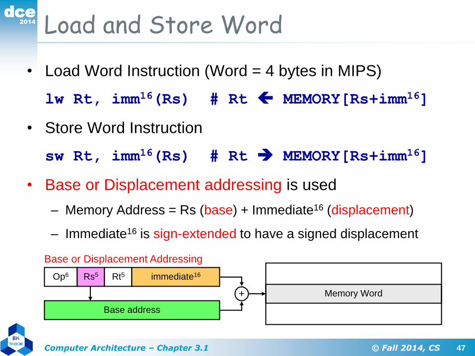
Load and Store Word
• Load Word Instruction (Word = 4 bytes in MIPS)
lw Rt, imm16(Rs) # Rt MEMORY[Rs+imm16]
• Store Word Instruction
sw Rt, imm16(Rs) # Rt MEMORY[Rs+imm16]
• Base or Displacement addressing is used
– Memory Address = Rs (base) + Immediate16 (displacement)
– Immediate16 is sign-extended to have a signed displacement
Op6 Rs5 Rt5 immediate16
Base or Displacement Addressing
Memory Word
Base address
+

2014
dce
48Computer Architecture – Chapter 3.1 © Fall 2014, CS
• Load/Store Instruction Format (I format):
lw $t0, 24($s3)
Load Instruction
35 19 8 2410
Memory
data word address (hex)
0x000000000x000000040x000000080x0000000c
0xf f f f f f f f
$s3 0x12004094
2410 + $s3 =
. . . 0001 1000
+ . . . 1001 0100
. . . 1010 1100 =
0x120040ac
0x120040ac$t0

2014
dce
49Computer Architecture – Chapter 3.1 © Fall 2014, CS
Byte Addresses• Since 8-bit bytes are so useful, most architectures
address individual bytes in memory
– Alignment restriction - the memory address of a word must be on
natural word boundaries (a multiple of 4 in MIPS-32)
• Big Endian: leftmost byte is word address
IBM 360/370, Motorola 68k, MIPS, Sparc, HP PA
• Little Endian: rightmost byte is word address
Intel 80x86, DEC Vax, DEC Alpha (Windows NT)
msb lsb
3 2 1 0little endian byte 0
0 1 2 3
big endian byte 0

2014
dce
50Computer Architecture – Chapter 3.1 © Fall 2014, CS
Example on Load & Store
• Translate A[1] = A[2] + 5 (A is an array of words)
– Assume that address of array A is stored in register $s0
lw $s1, 8($s0) # $s1 = A[2]
addiu $s2, $s1, 5 # $s2 = A[2] + 5
sw $s2, 4($s0) # A[1] = $s2
• Index of a[2] and a[1] should be multiplied by 4. Why?
sw
Memory
A[1]
A[0]
A[2]
A[3]
. . .
. . .
A+12
A+8
A+4
A
Registers
address of A$s0 = $16
value of A[2]$s1 = $17
A[2] + 5$s2 = $18
. . .
. . .
lw

2014
dce
51Computer Architecture – Chapter 3.1 © Fall 2014, CS
0 0
s s s
s s
0 0
s
bu
b
h
hu
sign – extend
zero – extend
sign – extend
zero – extend
32-bit Register
Load and Store Byte and Halfword
• The MIPS processor supports the following data formats:
– Byte = 8 bits, Halfword = 16 bits, Word = 32 bits
• Load & store instructions for bytes and halfwords
– lb = load byte, lbu = load byte unsigned, sb = store byte
– lh = load half, lhu = load half unsigned, sh = store halfword
• Load expands a memory data to fit into a 32-bit register
• Store reduces a 32-bit register to fit in memory

2014
dce
52Computer Architecture – Chapter 3.1 © Fall 2014, CS
Load and Store Instructions
Instruction Meaning I-Type Format
lb rt, imm16(rs) rt = MEM[rs+imm16] 0x20 rs5 rt5 imm16
lh rt, imm16(rs) rt = MEM[rs+imm16] 0x21 rs5 rt5 imm16
lw rt, imm16(rs) rt = MEM[rs+imm16] 0x23 rs5 rt5 imm16
lbu rt, imm16(rs) rt = MEM[rs+imm16] 0x24 rs5 rt5 imm16
lhu rt, imm16(rs) rt = MEM[rs+imm16] 0x25 rs5 rt5 imm16
sb rt, imm16(rs) MEM[rs+imm16] = rt 0x28 rs5 rt5 imm16
sh rt, imm16(rs) MEM[rs+imm16] = rt 0x29 rs5 rt5 imm16
sw rt, imm16(rs) MEM[rs+imm16] = rt 0x2b rs5 rt5 imm16
Base or Displacement Addressing is used
Memory Address = Rs (base) + Immediate16 (displacement)
Two variations on base addressing
If Rs = $zero = 0 then Address = Immediate16 (absolute)
If Immediate16 = 0 then Address = Rs (register indirect)

2014
dce
53Computer Architecture – Chapter 3.1 © Fall 2014, CS
Next . . .
• Instruction Set Architecture
• Overview of the MIPS Architecture
• R-Type Arithmetic, Logical, and Shift Instructions
• I-Type Format and Immediate Constants
• Jump and Branch Instructions
• Translating If Statements and Boolean Expressions
• Load and Store Instructions
• Translating Loops and Traversing Arrays
• Addressing Modes

2014
dce
54Computer Architecture – Chapter 3.1 © Fall 2014, CS
Translating a WHILE Loop
• Consider the following WHILE statement:
i = 0; while (A[i] != k) i = i+1;
Where A is an array of integers (4 bytes per element)
Assume address A, i, k in $s0, $s1, $s2, respectively
• How to translate above WHILE statement?
xor $s1, $s1, $s1 # i = 0
move $t0, $s0 # $t0 = address A
loop: lw $t1, 0($t0) # $t1 = A[i]
beq $t1, $s2, exit # exit if (A[i]== k)
addiu $s1, $s1, 1 # i = i+1
sll $t0, $s1, 2 # $t0 = 4*i
addu $t0, $s0, $t0 # $t0 = address A[i]
j loop
exit: . . .
Memory
A[2]
A[i]
A[1]
A[0]
. . .
. . .
A
A+4
A+8
A+4×i
. . .

2014
dce
55Computer Architecture – Chapter 3.1 © Fall 2014, CS
Using Pointers to Traverse Arrays
• Consider the same WHILE loop:
i = 0; while (A[i] != k) i = i+1;
Where address of A, i, k are in $s0, $s1, $s2, respectively
• We can use a pointer to traverse array A
Pointer is incremented by 4 (faster than indexing)
move $t0, $s0 # $t0 = $s0 = addr A
j cond # test condition
loop: addiu $s1, $s1, 1 # i = i+1
addiu $t0, $t0, 4 # point to next
cond: lw $t1, 0($t0) # $t1 = A[i]
bne $t1, $s2, loop # loop if A[i]!= k
• Only 4 instructions (rather than 6) in loop body

2014
dce
56Computer Architecture – Chapter 3.1 © Fall 2014, CS
Copying a String
move $t0, $s0 # $t0 = pointer to source
move $t1, $s1 # $t1 = pointer to target
L1: lb $t2, 0($t0) # load byte into $t2
sb $t2, 0($t1) # store byte into target
addiu $t0, $t0, 1 # increment source pointer
addiu $t1, $t1, 1 # increment target pointer
bne $t2, $zero, L1 # loop until NULL char
The following code copies source string to target string
Address of source in $s0 and address of target in $s1
Strings are terminated with a null character (C strings)
i = 0;
do {target[i]=source[i]; i++;} while (source[i]!=0);

2014
dce
57Computer Architecture – Chapter 3.1 © Fall 2014, CS
Summing an Integer Array
move $t0, $s0 # $t0 = address A[i]
xor $t1, $t1, $t1 # $t1 = i = 0
xor $s2, $s2, $s2 # $s2 = sum = 0
L1: lw $t2, 0($t0) # $t2 = A[i]
addu $s2, $s2, $t2 # sum = sum + A[i]
addiu $t0, $t0, 4 # point to next A[i]
addiu $t1, $t1, 1 # i++
bne $t1, $s1, L1 # loop if (i != n)
Assume $s0 = array address, $s1 = array length = n
sum = 0;
for (i=0; i<n; i++) sum = sum + A[i];

2014
dce
58Computer Architecture – Chapter 3.1 © Fall 2014, CS
Next . . .
• Instruction Set Architecture
• Overview of the MIPS Architecture
• R-Type Arithmetic, Logical, and Shift Instructions
• I-Type Format and Immediate Constants
• Jump and Branch Instructions
• Translating If Statements and Boolean Expressions
• Load and Store Instructions
• Translating Loops and Traversing Arrays
• Addressing Modes

2014
dce
59Computer Architecture – Chapter 3.1 © Fall 2014, CS
Addressing Modes
• Where are the operands?
• How memory addresses are computed?
Op6 Rs5 Rt5 immediate16
Base or Displacement Addressing
Word
Operand is in memory (load/store)
Register = Base address
+ HalfwordByte
Op6 Rs5 Rt5 immediate16
Immediate Addressing
Operand is a constant
Op6 Rs5 Rt5 Rd5 funct6sa5
Register Addressing
Register
Operand is in a register
2014
dce
60Computer Architecture – Chapter 3.1 © Fall 2014, CS
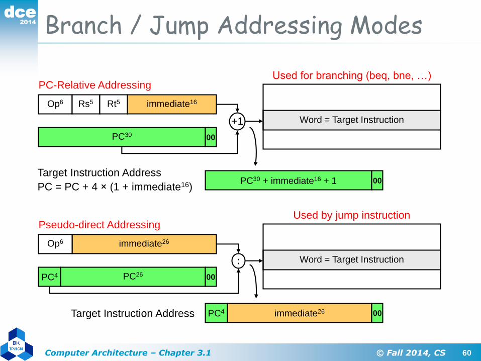
Branch / Jump Addressing Modes
Used for branching (beq, bne, …)
Word = Target Instruction
Op6 Rs5 Rt5 immediate16
PC-Relative Addressing
PC30 00
+1
Target Instruction Address
PC = PC + 4 × (1 + immediate16)PC30 + immediate16 + 1 00
immediate26PC4 00Target Instruction Address
Word = Target Instruction
immediate26Op6
Pseudo-direct Addressing
PC26
:
00
Used by jump instruction
PC4

2014
dce
61Computer Architecture – Chapter 3.1 © Fall 2014, CS
Jump and Branch Limits
Jump Address Boundary = 226 instructions = 256 MB
Text segment cannot exceed 226 instructions or 256 MB
Upper 4 bits of PC are unchanged
Branch Address Boundary
Branch instructions use I-Type format (16-bit immediate constant)
PC-relative addressing:
Target instruction address = PC + 4×(1 + immediate16)
Count number of instructions to branch from next instruction
Positive constant => Forward Branch, Negative => Backward branch
At most ±215 instructions to branch (most branches are near)
immediate26PC4 00Target Instruction Address
PC30 + immediate16 + 1 00
2014
dce
62Computer Architecture – Chapter 3.1 © Fall 2014, CS
Summary of RISC Design• All instructions are typically of one size
• Few instruction formats
• All operations on data are register to register
– Operands are read from registers
– Result is stored in a register
• General purpose integer and floating point registers
– Typically, 32 integer and 32 floating-point registers
• Memory access only via load and store instructions
– Load and store: bytes, half words, words, and double words
• Few simple addressing modes

2014
dce
63Computer Architecture – Chapter 3.1 © Fall 2014, CS
Four Design Principles
1. Simplicity favors regularity
– Fix the size of instructions (simplifies fetching & decoding)
– Fix the number of operands per instruction
• Three operands is the natural number for a typical
instruction
2. Smaller is faster
– Limit the number of registers for faster access (typically 32)
3. Make the common case fast
– Include constants inside instructions (faster than loading them)
– Design most instructions to be register-to-register
4. Good design demands good compromises
– Fixed-size instructions compromise the size of constants