chapter two: sketching, constraining and dimensions€¦ · autodesk inventor 6 essentials...
TRANSCRIPT

Autodesk Inventor 6 Essentials Instructor Guide
Chapter two: sketching, constraining and dimensioning 2- 1
Chapter Two: Sketching, Constraining and Dimensions
Chapter Outline
This is a description of the topics covered in this chapter, including the exercises. Topic: How to sketch, constrain and use dimensions Chapter Topics Estimated
Time (Hours)
# of PowerPoint
slides
Recommended Optional
2 Introduce how to sketch,
constrain and dimension
1 X
2 Review course objectives for
Chapter Two
1 X
2 Sketching and part applications
options
3
2 Units 1 X
2 Templates 1 X
2 Creating a part 2 X
2 Sketches overview 3 X
2 Exercise 2-1: Creating a sketch
with lines
1 X
2 Exercise 2-2: Creating a sketch
with tangencies
1.5
X
2 Constraining the sketch 3 X
2 Exercise 2-3: Adding and
displaying constraints
1 X
2 Adding Dimensions 4 X
2 Exercise 2-4: Dimensioning a
sketch
1 X
2 Summary of the chapter 1 X
2 Applying Your Skills: Exercises
2-1, 2-2
1 X
2 Review Checking Your Skills
answers at end of chapter
1.5
X
Total Estimated Hours 3 24

Autodesk Inventor 6 Essentials Instructor Guide
2- Chapter two: sketching, constraining and dimensioning
2
Slide 1
Autodesk Inventor® 6 www.autodesk.com
Autodesk Inventor 6Sketching, Constraining, and Dimensioning
Slide 2
Autodesk Inventor® 6 www.autodesk.com2
Objectives - Sketching, Constraining, and Dimensioning
Chapter ObjectivesSketch and part options
Sketching an outline of a part
Creating geometric constraintsDimensioning a sketch
Changing a dimension’s value in a sketch

Autodesk Inventor 6 Essentials Instructor Guide
Chapter two: sketching, constraining and dimensioning 2- 3
Slide 3
Autodesk Inventor® 6 www.autodesk.com
Sketching, Constraining, and Dimensioning
Sketching & Part Application Options
Slide 4
Autodesk Inventor® 6 www.autodesk.com4
Sketching & Part Application Options
Sketch OptionsCustomized your preferences
Settings are globalAffects all open & new Inventor documents
TRAINER NOTE
Emphasize that settings on tabs of the Application Options dialog box affect all
documents.

Autodesk Inventor 6 Essentials Instructor Guide
Chapter two: sketching, constraining and dimensioning
2-4
Slide 5
Autodesk Inventor® 6 www.autodesk.com5
Sketching & Part Application Options
Constraint Placement Priority
Display
Over-constrained Dimensions
Snap to Grid
Edit Dimensions when Created
AutoProject Edges During Curve Creation
Automatic Reference Edges for New Sketch
3D Sketch
TECHNICAL INFORMATION
• Snap to grid: Select this option to sketch geometry by snapping to the grid.
Clear this selection to sketch shapes freely without regard to size, and later
add and edit dimensions to resize geometry.
• Autoproject edges during curve creation: Selects existing geometry and
projects it into the current sketch by “rubbing” the lines. Projected geometry
is reference geometry and cannot be edited.
• Automatic reference edges for new sketch: Projects the edges of the
selected face into a new sketch. If you do not intend to use the face edges,
you may wish to turn this option off to avoid creating unneeded geometry.
• Edit dimension when created: Opens the edit dimension box when you
place a dimension. Used together with free sketching (grid snap off), this
option lets you add precision while still sketching quickly. Clear this check
box to place a dimension without editing. Double-click the dimension value
to change it later.

Autodesk Inventor 6 Essentials Instructor Guide
Chapter two: sketching, constraining and dimensioning 2- 5
Slide 6
Autodesk Inventor® 6 www.autodesk.com6
Sketching & Part Application Options
Part OptionsCustomized your preferences
Settings are globalAffects all open & new Inventor documents
Sketch on New Part Creation
Parallel View on Sketch Creation
Auto-Hide In-Line Work Features
Construction
TECHNICAL NOTES
The part tab sets
• preferences for the default sketch plane in a new part file
• orientation of the sketch view
• behavior of in-line work features after they are used by another work feature
• the appearance of construction surfaces,

Autodesk Inventor 6 Essentials Instructor Guide
Chapter two: sketching, constraining and dimensioning
2-6
Slide 7
Autodesk Inventor® 6 www.autodesk.com
Sketching, Constraining, and Dimensioning
Units & Templates
Slide 8
Autodesk Inventor® 6 www.autodesk.com8
Units
UnitsDefault unit of measurement
Part, Assembly & Drawing files
Template file
Changing - Overridden
Edit dimension
TECHNICAL NOTES
Options on the Document Settings tabs affect only the current document.
The Units tab:
• Specifies length, angle, time, and mass units.
• Specifies precision decimal places for linear and angular dimension
displays, and the dimension style.
Autodesk Inventor 6 Essentials Instructor Guide
Chapter two: sketching, constraining and dimensioning 2- 7
Slide 9
Autodesk Inventor® 6 www.autodesk.com9
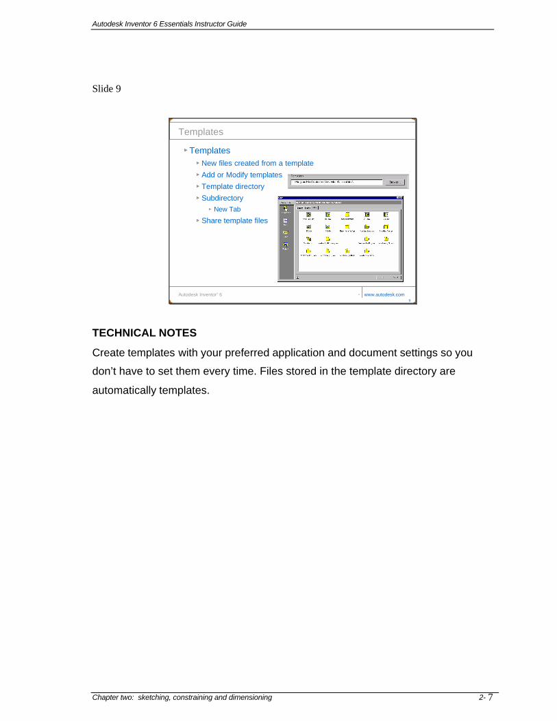
Templates
TemplatesNew files created from a template
Add or Modify templates
Template directory
SubdirectoryNew Tab
Share template files
TECHNICAL NOTES
Create templates with your preferred application and document settings so you
don’t have to set them every time. Files stored in the template directory are
automatically templates.

Autodesk Inventor 6 Essentials Instructor Guide
Chapter two: sketching, constraining and dimensioning
2-8
Slide 10
Autodesk Inventor® 6 www.autodesk.com
Sketching, Constraining, and Dimensioning
Creating a Part
Slide 11
Autodesk Inventor® 6 www.autodesk.com11
Creating a Part
Creating a PartStandard.ipt icon
File menu
Shortcut key
New icon
Part environment
Autodesk Inventor 6 Essentials Instructor Guide
Chapter two: sketching, constraining and dimensioning 2- 9
Slide 12
Autodesk Inventor® 6 www.autodesk.com12
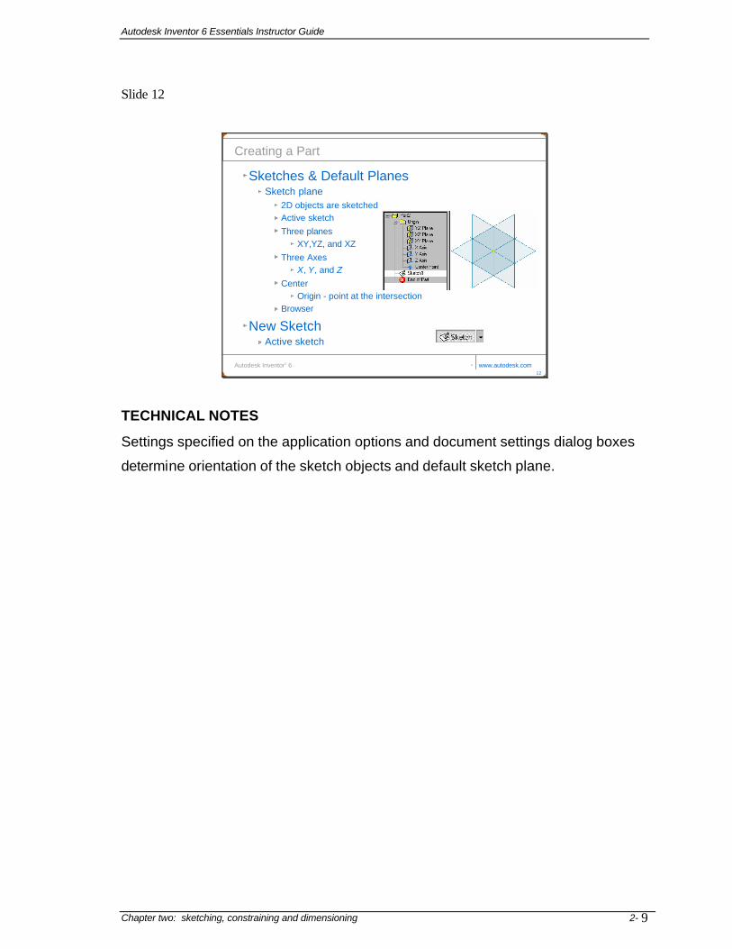
Creating a Part
Sketches & Default PlanesSketch plane
2D objects are sketchedActive sketchThree planes
XY,YZ, and XZThree Axes
X, Y, and ZCenter
Origin - point at the intersectionBrowser
New SketchActive sketch
TECHNICAL NOTES
Settings specified on the application options and document settings dialog boxes
determine orientation of the sketch objects and default sketch plane.

Autodesk Inventor 6 Essentials Instructor Guide
Chapter two: sketching, constraining and dimensioning
2-10
Slide 13
Autodesk Inventor® 6 www.autodesk.com
Sketching, Constraining, and Dimensioning
Sketch the Outline of the Part
Slide 14
Autodesk Inventor® 6 www.autodesk.com14
Sketch the Outline of the Part
Step 1 - Sketches OverviewSketching strategies, tools, & techniques
Outline Draw to finished size/shape
Visual Guide – distance & angle
No overlaps & gapsKeep it simple
Closed vs. Open shape
Sketch Tools34 sketching tools Expert mode on/off
TECHNICAL NOTES
Two ways to sketch in Inventor:
1. Use grid snap and coordinates displayed at lower right corner of the
graphics window to sketch to precise size.
2. Turn off grid snap and sketch freely without regard to size, then add
dimensions later to specify precise size.

Autodesk Inventor 6 Essentials Instructor Guide
Chapter two: sketching, constraining and dimensioning 2- 11
Slide 15
Autodesk Inventor® 6 www.autodesk.com15
Sketch the Outline of the Part
Using the Sketch ToolsVisual feedback
Line ToolPowerful tool
Endpoint - Arc
Inferred PointsDashed lines
Endpointshorizontalvertical
perpendicular

Autodesk Inventor 6 Essentials Instructor Guide
2- Chapter two: sketching, constraining and dimensioning
12
Slide 16
Autodesk Inventor® 6 www.autodesk.com16
Sketch the Outline of the Part
Automatic ConstraintsConstraint symbols
Scrubbingdifferent constraint appliedmove the cursor so it touches
Precise Inputspecified length or angle
Selecting Objectsindividually objectsmultiple objectscolor change
Deleting Objectsright-click
TECHNICAL NOTES
• Scrubbing: Brush the cursor along the line or curve you want to constrain
to, then move the cursor into the approximate desired position. In cases
where more than one constraint is possible, this technique overrides a
default constraint in favor of the constraint you selected.
• Precise input: enter exact coordinates for sketch geometry as you sketch.
• Selecting geometry: click and drag left to right to select all geometry
completely enclosed in the selection window.
• Click and drag right to left to select geometry enclosed and intersected by
the selection window.

Autodesk Inventor 6 Essentials Instructor Guide
Chapter two: sketching, constraining and dimensioning 2- 13
Slide 17
Autodesk Inventor® 6 www.autodesk.com17
Exercise 2-1
Creating A Sketch With Lines
Slide 18
Autodesk Inventor® 6 www.autodesk.com
Sketching, Constraining, and Dimensioning
Constraining the Sketch

Autodesk Inventor 6 Essentials Instructor Guide
2- Chapter two: sketching, constraining and dimensioning
14
Slide 19
Autodesk Inventor® 6 www.autodesk.com19
Constraining the Sketch
Step 2 - Geometric ConstraintsApply behavior
Create relationshipsfully constrainfix constrain
Constraint Types11 geometric constraints
TRAINER NOTE
Encourage students to view the Learn About Constraints video on the Getting
Started screen. Click File>Getting Started>Learn About Constraints.

Autodesk Inventor 6 Essentials Instructor Guide
Chapter two: sketching, constraining and dimensioning 2- 15
Slide 20
Autodesk Inventor® 6 www.autodesk.com20
Constraining the Sketch
Geometric ConstraintsAdding Constraints
Applying Over-constrain
Duplicate
“Adding this constraint will over-constrain the sketch”
SnapMidpoint, center & intersectionCoincident constraint

Autodesk Inventor 6 Essentials Instructor Guide
2- Chapter two: sketching, constraining and dimensioning
16
Slide 21
Autodesk Inventor® 6 www.autodesk.com21
Constraining the Sketch
Geometric ConstraintsDragging a Sketch
Constrained or NotGeometry stretches
Showing ConstraintsTo see applied constraints
Change color
Deleting ConstraintsRight-click
Show all & Hide all
TECHNICAL NOTES
Constraints are automatically inferred as you sketch. Add only the minimum
number of constraints needed to control the sketch shape.
Use Show All Constraints to identify which constraints have been inferred. If you
want geometry to have a different constraint, delete the unwanted constraint and
reapply a different constraint.

Autodesk Inventor 6 Essentials Instructor Guide
Chapter two: sketching, constraining and dimensioning 2- 17
Slide 22
Autodesk Inventor® 6 www.autodesk.com22
Exercise 2-3
Adding and Displaying Constraints
Slide 23
Autodesk Inventor® 6 www.autodesk.com
Sketching, Constraining, and Dimensioning
Adding Dimensions

Autodesk Inventor 6 Essentials Instructor Guide
Chapter two: sketching, constraining and dimensioning
2-18
Slide 24
Autodesk Inventor® 6 www.autodesk.com24
Adding Dimensions
Step 3 – Adding DimensionsAll dimensions created are parametricControl & change size of geometryGeneral Dimensioning
Create linear, angle, radial, or diameterAutomatically snapExtension linesPreview image
Dimensioning LinesEndpoints - twoLength
Dimensioning an AngleMidpoints of two lines
TECHNICAL NOTE
Sketch tab of the Application Options dialog box: select Edit dimension when
created option to immediately open the edit dimension box. To edit dimensions
later, clear the check box.

Autodesk Inventor 6 Essentials Instructor Guide
Chapter two: sketching, constraining and dimensioning 2- 19
Slide 25
Autodesk Inventor® 6 www.autodesk.com25
Adding Dimensions
Dimensioning Arcs and CirclesCircumferenceArc = radiusCircle = diameter
Diametric DimensionsRevolved partRepresent a quarter outlineLinear diameterAxis of rotation
Dimensioning to a QuadrantArc or circleConstraint symbol changesTwo quadrants
TECHNICAL NOTE:
Diametric dimensions are created by default if a centerline is included in the
dimension. For example, sketch a profile to revolve and change the axis of
revolution to a centerline style. When you apply a dimension, the value displayed
is the width of the revolved profile.

Autodesk Inventor 6 Essentials Instructor Guide
Chapter two: sketching, constraining and dimensioning
2-20
Slide 26
Autodesk Inventor® 6 www.autodesk.com26
Adding Dimensions
Entering and Editing a Dimension’s ValueAutomatically appear
Change the value
Edit Dimension option
Default value
To change double-click
Enter exact value
Accurate to six decimal places
Smallest dimensions first
Slide 27
Autodesk Inventor® 6 www.autodesk.com27
Adding Dimensions
Entering and Editing a Dimension’s Value
Repositioning a DimensionNew location
Origin points cannot be moved
Over-Constrained SketchesInventor will not allow
over-constrain
duplicate constraints
conflict with another constraint
Driven dimension
Reference dimension
Parentheses
Over-constrained dimensions option

Autodesk Inventor 6 Essentials Instructor Guide
Chapter two: sketching, constraining and dimensioning 2- 21
Slide 28
Slide 29
Autodesk Inventor® 6 www.autodesk.com29
Summary
Click the Create Dimension tool from the Sketch toolbar, or right -click in the graphics window and from the menu click Create Dimension or press the hot key D
Add parametric dimensions to a sketch
Click a constraint from the constraint flyout in the Sketch Panel Bar or Sketch toolbar, or right -click in the graphics window and click Create Constraint and choose the specific constraint from the menu
Add geometric constraints to a sketch
Use the 2D Sketch tools from either the Panel Bar or the toolbar
Sketch the outline of the part
Click the Sketch tool from the Standard toolbar then click a face, a work plane, or an existing sketch from the Browser. Or, click a face, a work plane, or an existing sketch from the Browser, and then click the Sketch tool from the Standard toolbar
Make a planar face, a work plane, or a non-active sketch in the active part the active sketch
Click the New icon in What To Do and then click the Standard.ipt icon from the Default tab, or click Standard ( unit).ipt from one of the other tabs
Create a new part file
Click Tools > Application Options and click the Part tabModify the Part options of Autodesk Inventor
Click Tools > Application Options and click the Sketch tab
Modify the Sketch options of Autodesk Inventor
ToolDo ThisTo
Autodesk Inventor ® 6 www.autodesk.com28
Exercise 2-4
Dimensioning A Sketch

Autodesk Inventor 6 Essentials Instructor Guide
Chapter two: sketching, constraining and dimensioning
2-22
Slide 30
Autodesk Inventor® 6 www.autodesk.com30
Applying Your Skills
Skill Exercise 2-1
Skill Exercise 2-2

Autodesk Inventor 6 Essentials Instructor Guide
2- Chapter two: sketching, constraining and dimensioning
23
Answers to Checking Your Skills Use this section to review the answers to the questions at the end of chapter two in the Essentials 6 manual..
1 True___ False___ When sketching, constraints are not applied to the sketch by default.
False. While sketching, small constraint symbols appear that represent geometric constraint(s) that will be applied to the object. If you do not want a constraint to be applied, hold down the CTRL key when the point is selected.
2 True___ False___ When sketching and a point is inferred, a constraint is applied to represent that relationship.
False, When inferred points are selected, no constraints (geometric rules such as horizontal, vertical, collinear, etc.) are applied from them. Using inferred points helps create more accurate sketches.
3 True___ False___ A sketch does not need to be fully constrained.
True, Autodesk Inventor does not force you to fully constrain a sketch. It is recommended to fully constrain a sketch, however, as this will allow you to better predict how a part will react when dimensions values are changed.
4 True___ False___ When working on an mm part, you cannot use English units.
False, The default unit for any value can be overridden by entering in the desired unit. 5 True___ False___ After a sketch is fully constrained, a dimension’s value cannot be changed.
False, To edit a dimension that has already been created, double-click on the value of the dimension and enter a new value in the Edit Dimension dialog box.
6 True___ False___ A driven dimension is another name for a parametric dimension.
False, A driven dimension is a reference dimension. It is not a parametric dimension it just reflects the size of the points to which it is dimensioned. A driven dimension will appear with parentheses around the dimensions value, like (30).
7 Explain how to draw an arc while still in the Line command.
While using the line tool move the cursor over an endpoint and a small circle will appear at that endpoint. Click on the small circle, and with the left mouse button pressed down, move the cursor in the direction that you want the arc to go. Depending upon how you move the mouse, up to eight different arcs can be drawn.
8 Explain how to remove a geometric constraint from a sketch.
Click the Show Constraints tool from the Sketch Panel Bar. Select an object and a row of constraint icons will appear, move the cursor over a constraint icon, the objects that are linked to that constraint will change color. Then, either click on it and then right-click, or right-click while the cursor is over the constraint and select Delete on the menu.
9 Explain how to change a vertical dimension to an aligned dimension while it is being created.
The technique to change the constraint is called scrubbing. To place a different constraint while sketching, move the cursor so it touches (scrubs) the other object to which the constraint should be related. Move the cursor back to its original location and the constraint symbol changes to reflect the new constraint.
10 Explain how to create a dimension between two quadrants of two arcs.
- Start the General Dimension tool. - Click an arc or circle that includes one of the quadrants to which it will be dimensioned. - Move the cursor over the quadrant of the second arc or circle to which it will be dimensioned. - Move the cursor over the quadrant until the constraint symbol changes to quadrant. - Click and then move the cursor until the dimension is in the correct location, and click.