chapter twenty-four: interference of light e 1of 15
TRANSCRIPT

, Phy
sics
, 5th
Edi
tion
Cha
pter
Tw
enty
-Fou
r: In
terf
eren
ce o
f Lig
ht
Page
1of
15 Chapter Twenty-Four: Interference of Light
interference patterns are produced when two (or more) coherent sources produce waves of the same frequency and amplitude which superimpose in the same region of space (ie they overlap).
sources are coherent when there is a constant phase relationship between the waves emitted by the sources.
Disp
lace
men
t
+ v e
-v e
W a v e le n g t h
A m p li t u d e
C re s t
T ro u g h
crest is the highest point of that portion of a transverse wave above the equilibrium position.
trough is the lowest point of that portion of a transverse wave below the equilibrium position.
destructive interference occurs if the amplitude of the resultant of two interfering waves is smaller than the amplitude of either wave.
constructive interference occurs if the amplitude of the resultant of two interfering waves is larger than the amplitude of either wave.
diffraction occurs when waves bend and spread out as they pass an obstacle or through a narrow opening. The amount of diffraction depends on the wavelength of the waves relative to the size of the obstacle. In the case of a narrow opening, the amount of bending increases as the size of the opening decreases.
diffraction grating consists of a large number of closely space parallel slits which diffract light incident on the grating. The diffracted light will exhibit a pattern of light and dark spaces due to constructive interference and destructive interference.
polarization is a property of light that indicates that light is a transverse wave phenomenon. A transverse wave is a wave in which the oscillations or vibrations of the wave are at right angles to the direction of motion of the wave. An electromagnetic wave in which the electric vector is vibrating in only one plane is said to be plane polarized.
G
ianc
oli

, Phy
sics
, 5th
Edi
tion
Cha
pter
Tw
enty
-Fou
r: In
terf
eren
ce o
f Lig
ht
Page
2of
15 Speed, Frequency and Wavelength
The back and forth vibratory motion (often called oscillatory motion) of a swinging pendulum or mass suspended on a spring produces a sine curve. This curve depicts a wave:
Disp
lace
men
t
+ v e
- v e
W a v e le n g t h
A m p l i t u d e
v
period1frequency =
C r e s t
T r o u g h
f = frequency in hertz (Hz)
Displacements are measured from the mean position. The wave comprises of a series of crests and troughs.
Wavelength (λ) is the distance from one crest to another crest, more generally the shortest distance between successive identical parts of the wave that are in phase. λ is measured in metres. Amplitude (A) is the distance of the maximum displacement point of the wave from the mean position. A is measured in metres. Frequency (f) is the number of to-and-fro vibrations in time. f is measured in cycles per second or hertz.
where Period (T) is the time taken to complete one oscillation.
Wave motion involves a transfer of energy from one point to another, with no net transfer of matter.
Wave Equation v = fλ where: v = speed or velocity of the wave (in m s-1)
λ = wavelength in metres (m).
Transverse Waves A wave where the motion of the oscillations of the wave are at right angles (perpendicular) to the direction of travel.
G
ianc
oli
It consists of a series of crests and troughs.

, Phy
sics
, 5th
Edi
tion
Cha
pter
Tw
enty
-Fou
r: In
terf
eren
ce o
f Lig
ht
Page
3of
15 Longitudinal Waves
The medium moves back and forth parallel to the direction in which the wave travels. The wave consists of a series of compressions and rarefactions.
R = r a r e f a c t io n
P a r t i c l eV i b r a t i o n
λ
C = c o m p r e s s i o nC CCCR RRR
Note: Transverse waves and longitudinal waves transfer the energy along the medium. The matter does not transfer but moves to and fro about a fixed position.
This relationship holds for all kinds of waves whether they are water waves, sound waves, radio waves, or light waves. The speed of light is a universal constant, c = 3.0 × 10⁸ m s-1 in a vacuum.
Note that a beam of light could: travel around the Earth 7.5 times in 1 second take 8 minutes to travel from the Sun to Earth take 4 years to reach the nearest star, Alpha Centauri. Electromagnetic Waves Light is energy that is emitted by accelerating electric charges – often electrons in atoms. This energy travels in a wave that is partly electric and partly magnetic.
Such a wave is an electromagnetic wave.
Light is a small portion of the broad family of electromagnetic waves that include radio waves, microwaves and x-rays.
The range of the electromagnetic waves is called the electromagnetic spectrum. The range of wavelengths in the visible spectrum is shown below. (1 nm = 1.0 × 10⁻⁹ m)
G
ianc
oli
, Phy
sics
, 5th
Edi
tion
Cha
pter
Tw
enty
-Fou
r: In
terf
eren
ce o
f Lig
ht
Page
4of
15 Wave Fronts
A wave front is a line on a surface on which all points are in phase at any instant. This means that when one point is at the crest, so are the others.
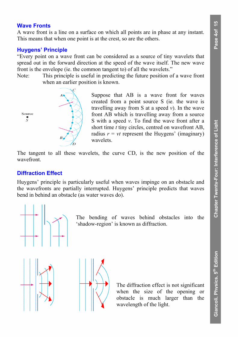
Huygens’ Principle “Every point on a wave front can be considered as a source of tiny wavelets that spread out in the forward direction at the speed of the wave itself. The new wave front is the envelope (ie. the common tangent to) of all the wavelets.” Note: This principle is useful in predicting the future position of a wave front
when an earlier position is known. Suppose that AB is a wave front for waves created from a point source S (ie. the wave is travelling away from S at a speed v). In the wave front AB which is travelling away from a source S with a speed v. To find the wave front after a short time t tiny circles, centred on wavefront AB, radius r = vt represent the Huygens’ (imaginary) wavelets.
The tangent to all these wavelets, the curve CD, is the new position of the wavefront.
Diffraction Effect Huygens’ principle is particularly useful when waves impinge on an obstacle and the wavefronts are partially interrupted. Huygens’ principle predicts that waves bend in behind an obstacle (as water waves do).
The bending of waves behind obstacles into the ‘shadow-region’ is known as diffraction.
The diffraction effect is not significant when the size of the opening or obstacle is much larger than the wavelength of the light.
G
ianc
oli

, Phy
sics
, 5th
Edi
tion
Cha
pter
Tw
enty
-Fou
r: In
terf
eren
ce o
f Lig
ht
Page
5of
15 Interference
A monochromatic light source emits a wave of a single colour and therefore has single frequency and wavelength in a vacuum(in air). e.g. Red light has wavelength of about 7.5×10⁻⁷m and hence a frequency of
about 4×10¹⁴Hz. Two sources are coherent if the waves created by them have a constant phase relationship. An interference pattern is observed only when the sources are coherent. If two tiny light bulbs are used as sources, an interference pattern would not be seen. The light emitted by one light globe would have a random phase with respect to the second light bulb. Two such sources, whose output waves bear no fixed relationship to each other, are called incoherent sources.
Wave Addition Wave Addition is the superposition of wave forms.
C r e s t + C r e s t
+ =
T r o u g h + T r o u g h
+ =
C o n s t r u c t i v eI n t e r f e r e n c e
DestructiveInterference
Crest + Trough
+ =
When waves overlap, interference is produced.
G
ianc
oli

, Phy
sics
, 5th
Edi
tion
Cha
pter
Tw
enty
-Fou
r: In
terf
eren
ce o
f Lig
ht
Page
6of
15 Young’s Double Slit Interference
Convincing evidence for the wave nature of light was provided by Thomas Young who was able to measure the wavelength of visible light using an interference effect.
If light from a single monochromatic source falls onto a screen containing two closely spaced slits S1 and S2, bright and dark fringes are seen on the screen behind.
Young realised that the bright fringes of light resulted from light waves from both holes (or slits) arriving crest to crest (constructive interference - more light). Similarly, the dark areas resulted from light waves arriving trough to crest (destructive interference - no light). Young’s experiment can done in the laboratory with two closely spaced holes
(or slits) with a sodium vapour lamp, light from which is passed through a single slit providing the monochromatic coherent source (a laser is even better because no first single slit is required only a double slit). The arrangement above is equivalent to two rocks being thrown into a lake, or when sound from two loudspeakers interferes. These two slits have circular waves leaving them because of the diffraction effect.
Using the diagrams below we can see how an interference pattern is produced on the screen.
(a) (b) The waves of wavelength λ are shown entering the slits S1 and S2 which are a distance apart d. The waves spread out in all directions after passing through the slits. The diagrams show only three different angles.
Diagram (a) shows that at the centre of the screen (θ=0°) the waves from each slit travel the same distance and are in phase. ie. a crest of one wave arrives at the same time as the crest of the other wave. Hence the amplitude of both waves add to form a larger amplitude and this is known as CONSTRUCTIVE INTERFERENCE and there is a bright spot in the centre of the screen.
G
ianc
oli

, Phy
sics
, 5th
Edi
tion
Cha
pter
Tw
enty
-Fou
r: In
terf
eren
ce o
f Lig
ht
Page
7of
15
Diagram (b) shows that at an angle θ the lower wave travels an extra distance of one whole wavelength, and the waves are in phase. Note that from the shaded triangle the extra distance equals d sinθ. At the point on the screen constructive interference occurs again since the paths of the two rays differs by one wavelength (or any whole number of wavelengths).
Diagram (c) shows that at this angle of θ the lower wave travels an extra distance equal to one-half wavelength, so that the two waves arrive at the screen fully out of phase. At this point on the scree since the extra distance travelled is one half wavelength (or 3/2λ, 5/2λ and so on) the two waves are exactly out of phase when they reach the screen: the crest of one wave arrives at the same time as the trough of the other and so produce zero amplitude.
This is DESTRUCTIVE INTERFERENCE and the screen is dark.
The pattern on the screen is a series of bright and dark lines (or fringes) as shown below.
Young’s Double Slit Interferometer The coherent sources produce a pattern of uniformly spaced bright (constructive interference) and dark (destructive interference) fringes. The point O is a maximum intensity or reinforcement since the wavelets from the sources S1 and S2 meet at O at the same time. The waves travelling from S1 and S2 to the screen will have a path difference. If the path difference (the extra distance travelled by one wavelet to reach the same point on the screen) is: an odd number of half wavelengths then DESTRUCTIVE INTERFERENCE an even number of half wavelengths then CONSTRUCTIVE INTERFERENCE.
G
ianc
oli
A constant phase relationship between the sources is a necessary condition for observable interference to occur, they are COHERENT (implies same λ). To achieve maximum contrast the amplitudes must be equal.
, Phy
sics
, 5th
Edi
tion
Cha
pter
Tw
enty
-Fou
r: In
terf
eren
ce o
f Lig
ht
Page
8of
15 SCREENDouble
SlitSingle
Slit
M O
P
LC
SS1
S2
θθ
d
x
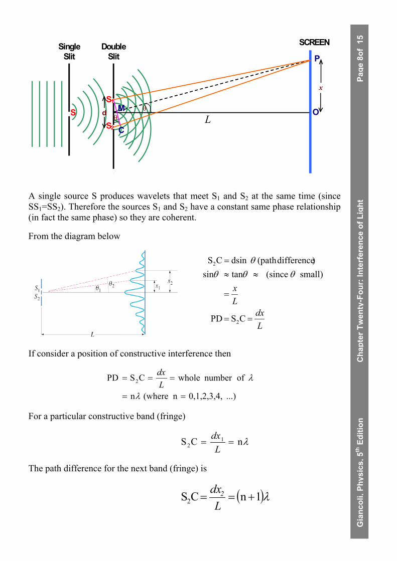
A single source S produces wavelets that meet S1 and S2 at the same time (since SS1=SS2). Therefore the sources S1 and S2 have a constant same phase relationship (in fact the same phase) so they are coherent.
From the diagram below
Ldx
Lx
==
=
≈≈=
CSPD
small) (since tansin)difference(path dsinCS
2
2
θθθθ
If consider a position of constructive interference then
...)0,1,2,3,4,n (where n
ofnumber wholeCSPD 2
==
===
λ
λLdx
For a particular constructive band (fringe)
nC 12 λ=
LdxS =
The path difference for the next band (fringe) is
( ) 1n λ+=L
dx2CS2 =
G
ianc
oli
, Phy
sics
, 5th
Edi
tion
Cha
pter
Tw
enty
-Fou
r: In
terf
eren
ce o
f Lig
ht
Page
9of
15 Rearranging these two equations so that x is the subject of the formulae gives:
dLx λn
1 =
( )
dLx λ1n
2+
=
( )d
Ld
Lxx λλ n1nW 12 −+
=−=
dLλ
=W
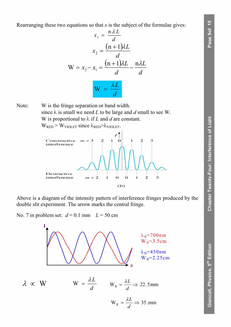
Note: W is the fringe separation or band width. since λ is small we need L to be large and d small to see W. W is proportional to λ if L and d are constant. WRED > WVIOLET since λRED>λVIOLET.
Above is a diagram of the intensity pattern of interference fringes produced by the double slit experiment. The arrow marks the central fringe.
No. 7 in problem set: d = 0.1 mm L = 50 cm
I
x
λ B=450nmW B=2.25cm
λ R=700nmW R=3.5cm
W∝λ dLλ
=W mm522WB .dL
⇒=λ
G
ianc
oli
mm.35WR ⇒=dLλ

, Phy
sics
, 5th
Edi
tion
Cha
pter
Tw
enty
-Fou
r: In
terf
eren
ce o
f Lig
ht
Page
10o
f 15
Diffraction Gratings Transmission Diffraction Gratings We have discussed diffraction before with regard to water waves as well as light and we now have seen that it refers to the spreading or bending of light around edges. Diffraction patterns of (a) a penny, (b) a razor blade and (c) a slit, each illuminated by a (nearly) point source of monochromatic light.
A diffraction pattern exists around any sharp object illuminated by a point source. This resembles the interference fringes of a double slit and is due to the waves being diffracted around the object.
Diffraction Grating A large number of equally spaced parallel slits is called a diffraction grating, although it may be more appropriate to use the term interference grating.
d
The grating can be made by precision machinery by scratching very fine parallel lines on a glass plate. The untouched spaces between the lines serve as the slits. Photographic transparencies of the original grating serve as an inexpensive grating.
Transmission Grating A transmission grating is a glass slab on which a large number of lines have been scratched so that the spacings of scratches is very small (eg. 10,000 scratches per cm). The light is passed through the transparent part thus supplying a many slit source.
Reflection Grating A reflection diffraction grating is a mirror surface on which a large number of lines have been scratched. The light is reflected from the smooth reflecting surface, eg. compact disc. Both operate similarly except that the reflection grating is preferred as less energy from the incident light is absorbed. These are also the most expensive. Reflection gratings are also useful as ultra-violet and infrared light are absorbed by glass.
G
ianc
oli

, Phy
sics
, 5th
Edi
tion
Cha
pter
Tw
enty
-Fou
r: In
terf
eren
ce o
f Lig
ht
Page
11o
f 15
The analysis of the diffraction grating is much like that of Young’s double-slit experiment. We assume parallel rays of light are incident on the grating.
Since this light is parallel there is a need for it to be focussed by a convex lense or even the lense in our eye. We also assume that the slits are narrow enough so that diffraction by each of them spreads light over a very wide angle on a screen and interference can occur with light from all other slits.
Light rays that pass through each slit without deviation (θ=0°) interfere constructively to
produce a bright line at the centre of the screen.
Constructive interference also occurs at an angle θ such that the rays from adjacent slits travel an extra distance of ∆l = mλ, where m is an integer.
For constructive interference
...) 2, 1, 0,(mmsin
==∆= λθ ld
These are the principal maxima and this is the criterion to have a maximum brightness. Note previously in interference: S2C = path difference = d sin θ m is the order of the pattern eg m = 1 dsinθ=mλ=λ m = 2 dsinθ=mλ=2λ etc.
G
ianc
oli

, Phy
sics
, 5th
Edi
tion
Cha
pter
Tw
enty
-Fou
r: In
terf
eren
ce o
f Lig
ht
Page
12o
f 15
When white light is passed through the grating, each wavelength produces constructive interference at a different angle and so a series of spectra are produced.
(a) a line spectrum with two wavelengths of light, 400 nm and 700 nm.
(b) Diffraction produced by white light.
the shorter wavelengths (blue) are diffracted through smaller angles than the longer wavelengths (red),
and the 1st order spectrum will show less dispersion (spread) than the 2nd order.
the intensity of the 1st order spectrum is greater than the intensity of the 2nd order because of diffraction causing greater dispersion.
Diffraction Grating: Lines Calculate the first and second order angles for light of wavelength 400 nm and 700 nm if the grating contains 10,000 line/cm. The grating contain 104lines/cm=106lines/m, which means the separation between slits is d=(1/106)m=1.0×10-6m. In first order (m=1), the angles are:
appear. willordershigher No 1. exceedcannot sin because 700nm
forexist not doesorder second but the 053 so1sin
0.800m101.0
104.02msin
order secondIn 044 and 623 so
0.700sin
0.400m101.0
104.01msin
400
700
6-
7-
400
700400
700
6-
-7
400
θλθθ
λθ
θθθ
λθ
=°=
=×
××==
°=°==
=×
××==
.
d
...
d
f
G
ianc
oli

, Phy
sics
, 5th
Edi
tion
Cha
pter
Tw
enty
-Fou
r: In
terf
eren
ce o
f Lig
ht
Page
13o
f 15
Spectra Overlap White light containing wavelengths from 400 nm to 750 nm strikes a grating containing 4000 lines/cm. Show that the blue at λ=450 nm of the third order spectrum overlaps the red at 700 nm of the second order. The grating spacing is d = (1/4000) cm = 2.50 ×10⁻⁶ m. The blue of the third order occurs at an angle θ given by:
0.540m102.50
104.503msin 6-
-7
=×
××==
dλθ
Red in second order occurs at:
0.560m102.50
10.0072msin 6-
-7
=×
××==
dλθ
which is a greater angle; so the second order overlaps into the beginning of the third-order spectrum.
Activities
1. Consider Summary (pg. 679)
2. Questions (pg. 680: no.1, 2, 3, 11)
3. Problems (pg. 681: no 10, 11, 12, 13, 14, 15, 16, 17)
4. Look over Summary (pg. 751)
5. Look over Problem Solving: Interference (pg. 750)
6. Sample Questions
7. Questions (pg. 752: no.1, 2, 4, 5, 6, 9)
8. Problems (pg 752-3: no 2, 3, 4, 5)
9. Questions (pg. 752: no.13, 14)
10. Problems (pg 752-3: no.18, 19, 26, 27, 28, 29, 30, 31, 32.)
G
ianc
oli

, Phy
sics
, 5th
Edi
tion
Cha
pter
Tw
enty
-Fou
r: In
terf
eren
ce o
f Lig
ht
Page
14o
f 15
SPECKLE Speckle is produced whenever a laser beam is reflected from a rough surface. Each point on the surface reflects light in a different direction, as shown in the diagram below. The light, which reaches each observer, will therefore have travelled through many different paths. Because the surface is rough, the angle of incidence and hence that of reflection of the coherent light "rays" in the incident beam will vary. At one location (P for example) the interference may be mostly constructive, depending on the path difference of the rays, and produce a bright speckle. The interference at P' may be mostly destructive and thus produce a dark speckle.
Note that even the diffraction (interference) patterns due to double slits and gratings can be produced using a Na lamp (for example), speckle interference patterns can only be produced using a laser. Why? Because the rays which interfere at each observation, travel along paths which are significantly different in length. The roughness of the surface should be comparable with (or greater than) the wavelength of the laser light. Wavelets coming (reflected) from different sections of the rough surface will overlap to give an interference pattern that will be seen on a screen as an irregular array of dot-like "speckles". Whenever the screen is placed, the speckles will be seen, as the interference effects occurring within the total region in which the reflected wavelets overlap (this assumes the knowledge of Huygen's wavelets)
G
ianc
oli
G
ianc
oli,
Phys
ics,
5th
Edi
tion
Cha
pter
Tw
enty
-Fou
r: In
terf
eren
ce o
f Lig
ht
Page
15o
f 15
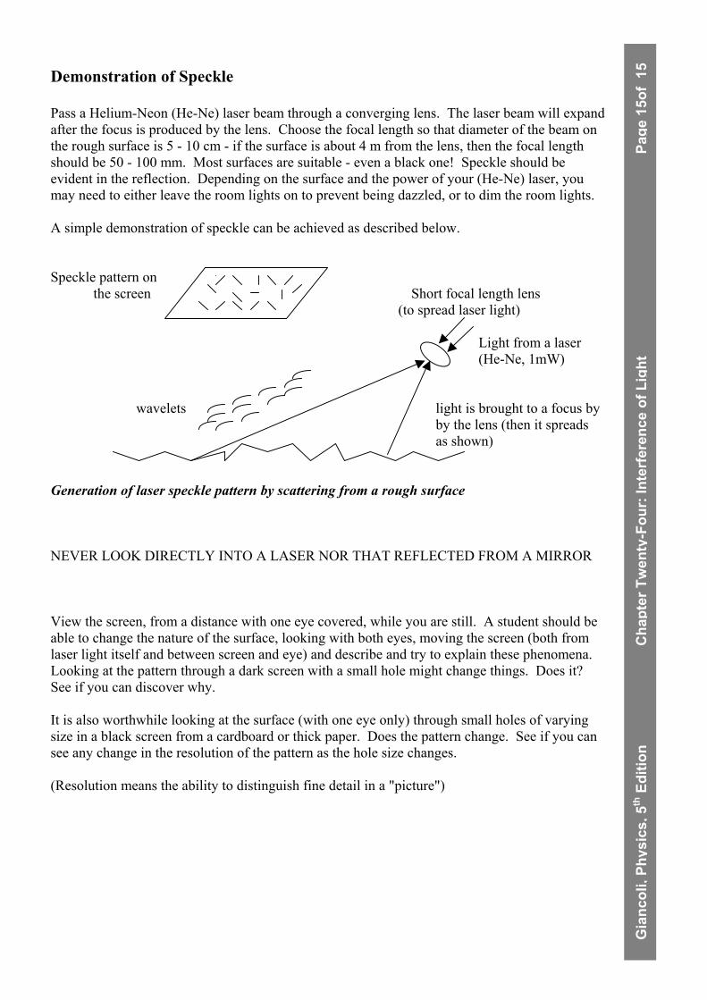
Demonstration of Speckle Pass a Helium-Neon (He-Ne) laser beam through a converging lens. The laser beam will expand after the focus is produced by the lens. Choose the focal length so that diameter of the beam on the rough surface is 5 - 10 cm - if the surface is about 4 m from the lens, then the focal length should be 50 - 100 mm. Most surfaces are suitable - even a black one! Speckle should be evident in the reflection. Depending on the surface and the power of your (He-Ne) laser, you may need to either leave the room lights on to prevent being dazzled, or to dim the room lights. A simple demonstration of speckle can be achieved as described below. Speckle pattern on the screen Short focal length lens (to spread laser light) Light from a laser (He-Ne, 1mW) wavelets light is brought to a focus by by the lens (then it spreads as shown) Generation of laser speckle pattern by scattering from a rough surface NEVER LOOK DIRECTLY INTO A LASER NOR THAT REFLECTED FROM A MIRROR View the screen, from a distance with one eye covered, while you are still. A student should be able to change the nature of the surface, looking with both eyes, moving the screen (both from laser light itself and between screen and eye) and describe and try to explain these phenomena. Looking at the pattern through a dark screen with a small hole might change things. Does it? See if you can discover why. It is also worthwhile looking at the surface (with one eye only) through small holes of varying size in a black screen from a cardboard or thick paper. Does the pattern change. See if you can see any change in the resolution of the pattern as the hole size changes. (Resolution means the ability to distinguish fine detail in a "picture")