chapter striations in plasma column - information and...
TRANSCRIPT
Chapter 5
Striations in Plasma Column
The studies carried out so far on surface wave produced plasma column, which
acts as a monopole plasma antenna is demonstrated in the previous chapters. We
now turn towards possible application of plasma properties which enable us to pro
vide different structures of plasma. There is however plenty of scope in imposing
the performance of different plasma structures as different plasma antennas. For
this purpose, we begin our studies on plasma structures or striations. Hence, the
objective in this chapter is to investigate the formation of striations and their phys
ical properties in the surface wave produced plasma column. It is well-known that
the glow discharge manifests into dark and bright luminous layers from cathode to
anode, namely, Aston dark space, cathode glow, cathode dark space, negative glow,
Faraday dark space, positive column, anode dark space and anode glow. Sometimes
a positive column in glow discharge has a periodic layered structure composed of
striations. Although glow discharges at low pressures using DC, RF, laser beam
etc have been studied for long time, even then it is of academic interest due to its
several manifestations which are challenging to scientists. Production of stationary
and moving striations is a good example of manifestation of a glow discharge. In
fact, striatio11:s are the periodic changes in electron density and are caused not by
redistribution of a fixed number of electrons, but by alternate regions of predom
inant production and removal of electrons which can survive in a limited range of
current values (lo-4 A to 10 A), pressure (lo-3 Torr to 102 Torr), gas species (rare
and molecular gases) and tube radius (1 em to 10 em). It has been established
87
Chapter 5: Striations in Plasma Column 88
that the striations are due to ionization instability or manifestations of ionization
oscillations and waves [1-7], which may be caused by step-wise ionization, the max
imization of the electron distribution function, and by any agent causing enhance
ment in inhomogeneities in plasma. On the basis of visual observations, two types of
striations have been classified: standing (stationary) striations, which have a static
appearance, and moving striations, which have certain velocity [8, 9]. Striations
have been observed in different plasmas in different discharge mechanism such as
DC-discharge [10], RF plasma [11-14], laser plasmas [15], ionosphere plasmas [16],
plasma display cells [17] etc. Analysis of three-dimensional striations was being
conducted using computerized tomography [18] with continuing research from the
view point of ionization [19]. Three-dimensional spherical stationary striations have
been also studied [20-23]. Robertson and Hawkins [13] found striations in a neutral
collision dominated, RF -exited Argon plasma in a uniform axial magnetic field. The
authors [13] found plasma to display a symmetric brightly glowing stationary stria
tions or balls. Number of balls and their radial and axial dimensions were pressure
dependent and not related to the applied frequency or wavelength. Robertson and
Herring [14] tried to explain this phenomenon by violation of ambipolar diffusion
due to the absence of the magnetic field.
R. A. Goldstein [24] interpreted the phenomena of balls or stationary striations
using the theory of bifurcation in which the system bifurcates after the onset of a
weak instability. The theory treated a system governed by a set of nonlinear equa
tions that has a stationary state which becomes unstable when a parameter, which
is called bifurcation parameter, a function of experimental parameters, exceeds a
critical value and small perturbations in the system grow nonlinearly. The plasma
settles down to a final state in which the density varies sinusoidally along the axis
of the cylinder (glass tube). The number of balls (bright regions) is an indication
of the number of modes to which the system has settled. The modes can be ex
cited with positive or negative amplitude depending on plasma parameters. The
theory also indicated that a gas with metastable state should be used to obtain the
phenomenon.
Although a vast literature exists on striations in the different discharge mecha
nism, stationary striations in surface wave produced plasma columns in which both
Chapter 5: Striations in Plasma Column 89
the electrodes are at one end of the glass tube, has not been still reported in the
available literature. Hence, our first objective is to study the stationary striations
and their physical properties in such plasma column.
In this chapter, we devote our attention to the study of experimental conditions
to form stationary striations and variation in the physical properties of such stria
tions with operating parameters such as input power, working pressure etc. Electric
field profile of striations is also studied. To provide a more qualitative understanding
of such striations, a discussion as a model for explaining the experimental results of
stratified plasma column is presented with the help of concept of bifurcation the
ory of Ronald A. Goldstein (24J considering the effect of two-step ionization in the
surface wave produced plasma column.
5.1 Formation of Striations
By changing the external operating parameters such as working pressure (0.03
mbar to 0.30 mbar), driven frequency (3 MHz to 10 MHz), input power (40 watts to
60 watts), radius of glass tube (1.5 em to 2.5 em), length of plasma column (5cm to 30
em) and Argon gas at certain critical conditions the plasma column is transformed in
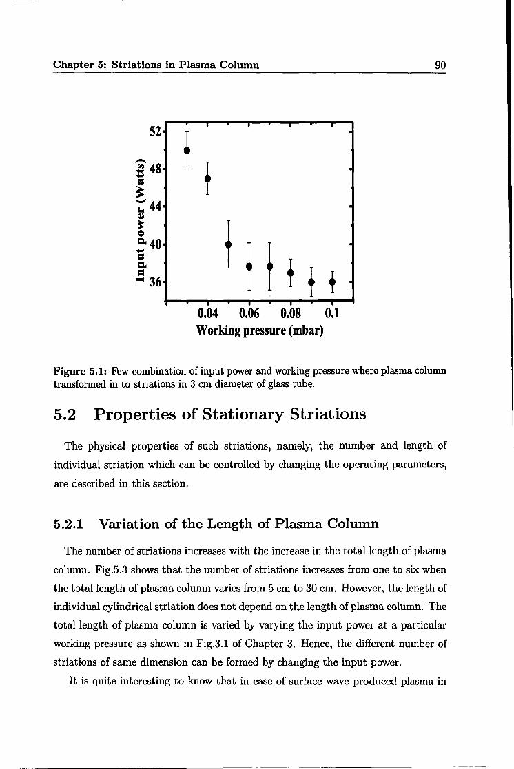
to finite number of cylindrical stationary striations. Fig.5.1 shows the few of critical
values, which are the combinations of input power and working pressure where the
stationary cylindrical striations are formed at constant driven frequency (5 MHz)
and length of plasma column (30 em). In fact, these structures in plasma column
are transformed from a stable visible inhomogeneous plasma column to unstable
inhomogeneous state, which again diffuses to stable visible inhomogeneous steady
state with non-uniform plasma structures like striations. A photograph of striations
is s~own in Fig.5.2 in which five striations can be visualized in 25 em long plasma
column. It can be seen that length of first striation is maximum and subsequently
the length of next striation decreases. Now, in order to investigate, we will study
about variation in the physical properties of striations with operating parameters in
the next section.
Chapter 5: Striations in Plasma Column 90
52 I I I
f f
.
. .
. .
.
t t t .
. f f + . I I I I
0104 0106 0.08 0.1 Working pressure (mbar)
Figure 5.1: Few combination of input power and working pressure where plasma column transformed in to striations in 3 em diameter of glass tube.
5.2 Properties of Stationary Striations
The physical properties of such striations, namely, the number and length of
individual striation which can be controlled by changing the operating parameters,
are described in this section.
5.2.1 Variation of the Length of Plasma Column
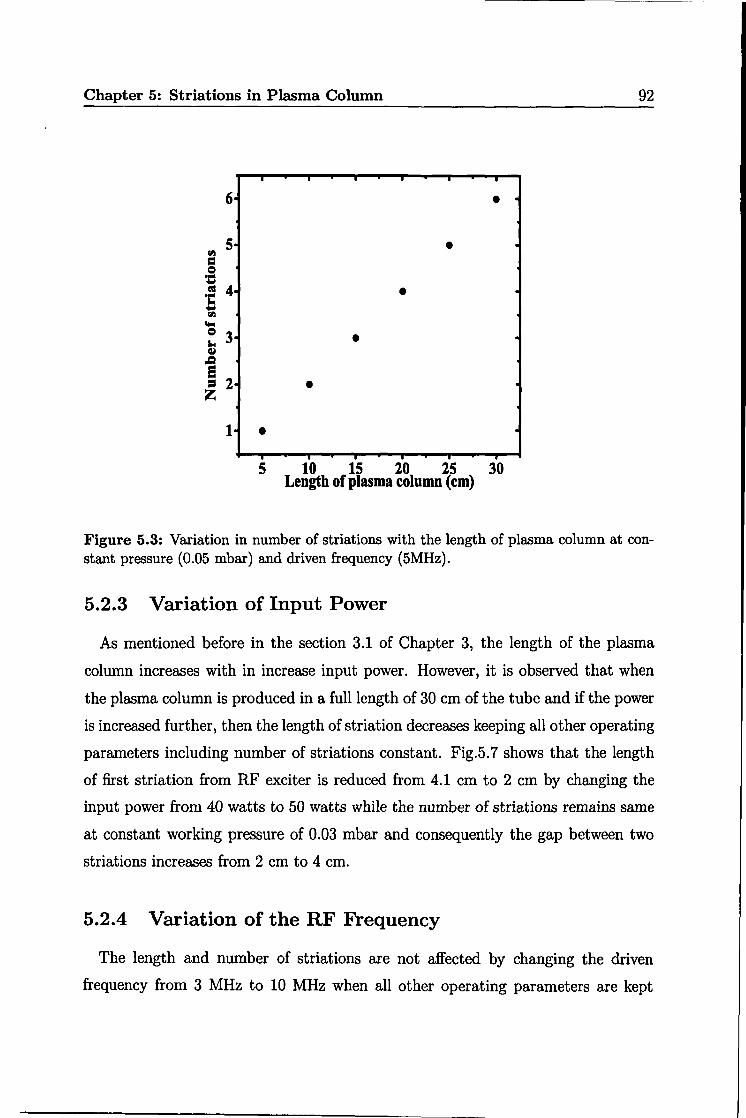
The number of striations increases with the increase in the total length of plasma
column. Fig.5.3 shows that the number of striations increases from one to six when
the total length of plasma column varies from 5 em to 30 em. However, the length of
individual cylindrical striation does not depend on the length of plasma column. The
total length of plasma column is varied by varying the input power at a particular
working pressure as shown in Fig.3.1 of Chapter 3. Hence, the different number of
striations of same dimension can be formed by changing the input power.
It is quite interesting to know that in case of surface wave produced plasma in
Chapter 5: Striations in Plasma Column 91
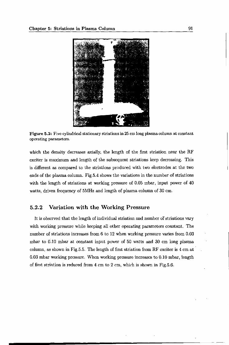
Figure 5.2: Five cylindrical stationary striations in 25 em long plasma column at constant operating parameters.
which the density decreases axially, the length of the first striation near the RF
exciter is maximum and length of the subsequent striations keep decreasing. This
is different as compared to the striations produced with two electrodes at the two
ends of the plasma column. Fig.5.4 shows the variations in the number of striations
with the length of striations at working pressure of 0.05 mbar, input power of 40
watts, driven frequency of 5MHz and length of plasma column of 30 em.
5.2.2 Variation with the Working Pressure
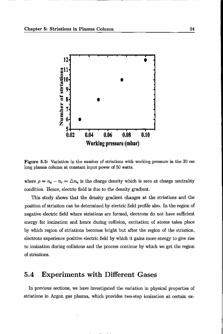
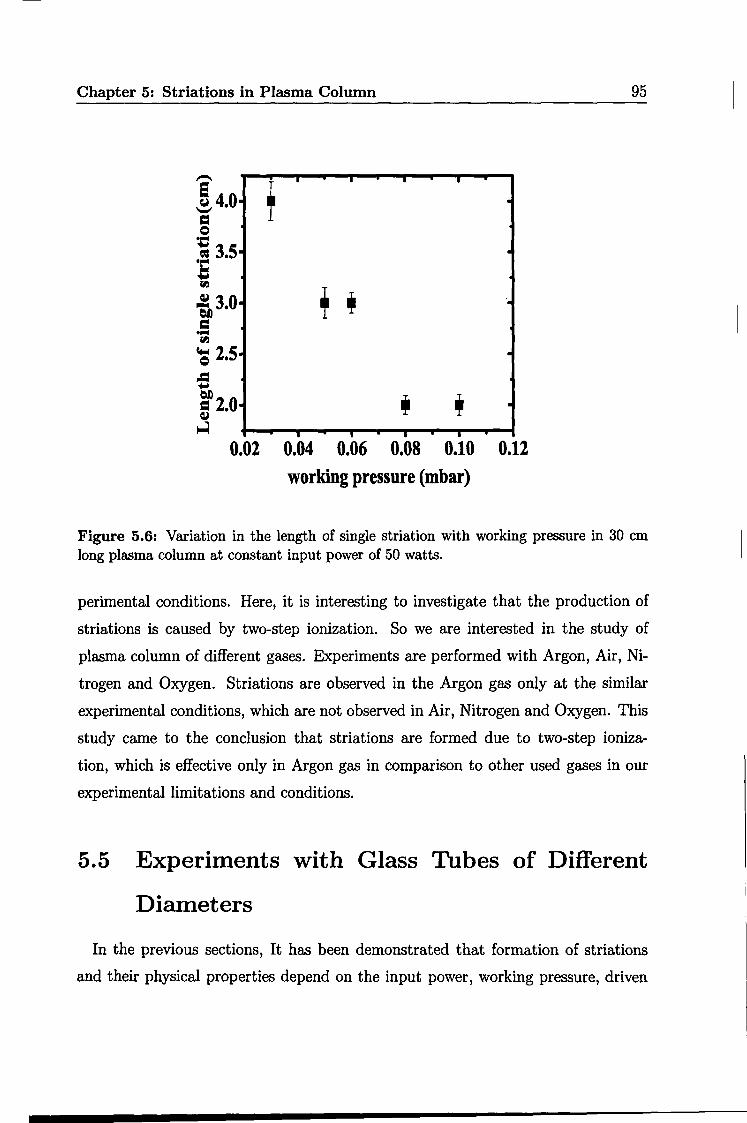
It is observed that the length of individual striation and number oi striations vary
with working pressure while keeping all other operating parameters constant. The
number of striations increases from 6 to 12 when working pressure varies from 0.03
mbar to 0.10 mbar at constant input power of 50 watts and 30 em long plasma
column, as shown in Fig.5.5. The length of first striation from RF exciter is 4 em at
0.03 mbar working pressure. When working pressure increases to 0.10 mbar, length
of first striation is reduced from 4 em to 2 em, which is shown in Fig.5.6.
Chapter 5: Striations in Plasma Column 92
. . . 6 •
5 • fl.l
= = ~ = 4· • ·c .... fl.l
c.. = 3 • .. ~ .c
~ 2 • z
1· • . I . . . 5 10 15 20 25
Length of plasma column (em) 30
Figure 5.3: Variation in number of striations with the length of plasma column at constant pressure (0.05 mbar) and driven frequency (5MHz).
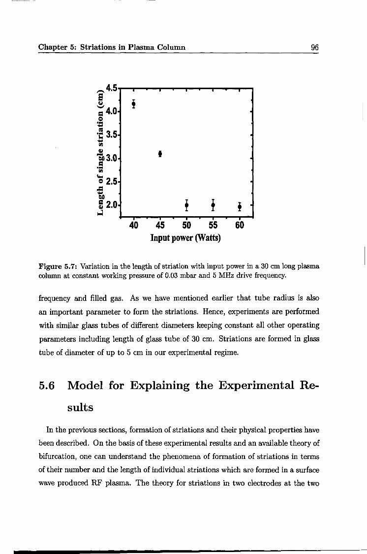
5.2.3 Variation of Input Power
As mentioned before in the section 3.1 of Chapter 3, the length of the plasma
column increases with in increase input power. However, it is observed that when
the plasma column is produced in a full length of 30 em of the tube and if the power
is increased further, then the length of striation decreases keeping all other operating
parameters including number of striations constant. Fig.5. 7 shows that the length
of first striation from RF exciter is reduced from 4.1 em to 2 em by changing the
input power from 40 watts to 50 watts while the number of striations remains same
at constant working pressure of 0.03 mbar and consequently the gap between two
striations increases from 2 em to 4 em.
5.2.4 Variation of the RF Frequency
The length and number of striations are not affected by changing the driven
frequency from 3 MHz to 10 MHz when all other operating parameters are kept

Chapter 5: Striations in Plasma Column 93
- I I I I I --. a 5.5· • . u ; 5.0· . ~ 4.5· + . ~ :s 4.0· . fl.l -= 3.5· . u a1 3.0· • . c.. Q 2.5· + +: -= !., 2.0· = ~ 1.5· .
I I I I I I
1 2 3 4 5 6 Striation number
Figure 5.4: Variations in the length of striations with the number of striations at working pressure of 0.05 mbar, input power of 40 watts, drive frequency of 5 MHz and length of plasma column of 30 em.
constant.
The results of experiments of this section suggest that the length and number of
striations can be controlled by operating parameters.
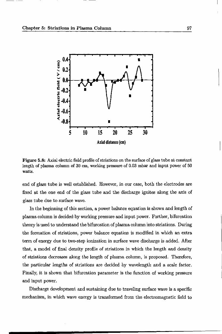
5.3 Electric Field Profile
To provide a more qualitative understanding of formation of striations (bright and
dark regions) due to electric field and study of plasma density gradient, experiments
are conducted, which are described in this section. Electric field on the surface of
plasma column with striations along the axis of glass tube is measured with the
dipole probe. Profile is shown in Fig.5.8, in which solid line with squares shows the
axial electric field profile with striations. Electric field is negative, positive and zero
for striations. Electric field is due to the electron density gradient can be written as
p 'VE= --
co (5.1)
Chapter 5: Striations in Plasma Column 94
12· I .
i . fljll· =
. = ~10· • . •• .. 9· . .... flj c.
8· = • . .. ~ .c 7· . m 6 • . z
5 I I
0.02 0.04 0.06 0.08 0.10 Working pressure (mbar)
Figure 5.5: Variation in the number of striations with working pressure in the 30 em long plasma column at constant input power of 50 watts.
where p = ne- ni = b.ne is the charge density which is zero at charge neutrality
condition. Hence, electric field is due to the density gradient.
This study shows that the density gradient changes at the striations and the
position of striation can be determined by electric field profile also. In the region of
negative electric field where striations are formed, electrons do not have sufficient
energy for ionization and hence during collision, excitation of atoms takes place
by which region of striations becomes bright but after the region of the striation,
electrons experience positive electric field by which it gains more energy to give rise
to ionization during collisions and the process continue by which we get the region
of striations.
5.4 Experiments with Different Gases
In previous sections, we have investigated the variation in physical properties of
striations in Argon gas plasma, which provides two-step ionization at certain ex-
Chapter 5: Striations in Plasma Column 95
,-.. • • • • e T ~4.0· .
= Q : = 3.5· . ... a. .... Ill
+ ~ 3.0· ' ·. ct)
= ... Ill
'Q 2.5· . -= .... ct)
iii ' = 2.0· . ~
~ • • • . 0.02 0.04 0.06 0.08 0.10 0.12
working pressure (mbar)
Figure 5.6: Variation in the length of single striation with working pressure in 30 em long plasma column at constant input power of 50 watts.
perimental conditions. Here, it is interesting to investigate that the production of
striations is caused by two-step ionization. So we are interested in the study of
plasma column of different gases. Experiments are performed with Argon, Air, Ni
trogen and Oxygen. Striations are observed in the Argon gas only at the similar
experimental conditions, which are not observed in Air, Nitrogen and Oxygen. This
study came to the conclusion that striations are formed due to two-step ioniza
tion, which is effective only in Argon gas in comparison to other used gases in our
experimental limitations and conditions.
5.5 Experiments with Glass Tubes of Different
Diameters
In the previous sections, It has been demonstrated that formation of striations
and their physical properties depend on the input power, working pressure, driven
Chapter 5: Striations in Plasma Column 96
~415 I I I I
e ! ~ = 410 I
= ~
= ~c 3~5 I .... fll
~ I "Sb3101 . = I ...
fll lot-I = 215 . .c .... 1:)!)
! ~ 2~0· ! ! . ~
I I I I I
40 45 50 55 60 Input power (Watts)
Figure 5. 7: Variation in the length of striation with input power in a 30 em long plasma column at constant working pressure of 0.03 mbar and 5 MHz drive frequency.
frequency and filled gas. As we have mentioned earlier that tube radius is also
an important parameter to form the striations. Hence, experiments are performed
with similar glass tubes of different diameters keeping constant all other operating
parameters including length of glass tube of 30 em. Striations are formed in glass
tube of diameter of up to 5 em in our experimental regime.
5.6 Model for Explaining the Experimental Re-
suits
In the previous sections, formation of striations and their physical properties have
been described. On the basis of these experimental results and an available theory of
bifurcation, one can understand the phenomena of formation of striations in terms
of their number and the length of individual striations which are formed in a surface
wave produced RF plasma. The theory for striations in two electrodes at the two
Chapter 5: Striations in Plasma Column 97
5 10 15 20 25 30 Axial distance (em)
Figure 5.8: Axial electric field profile of striations on the surface of glass tube at constant length of plasma column of 30 em, working pressure of 0.03 mbar and input power of 50 watts.
end of glass tube is well established. However, in our case, both the electrodes are
fixed at the one end of the glass tube and the discharge ignites along the axis of
glass tube due to surface wave.
In the beginning of this section, a power balance equation is shown and length of
plasma column is decided by working pressure and input power. Further, bifurcation
theory is used to understand the bifurcation of plasma column into striations. During
the formation of striations, power balance equation is modified in which an extra
term of energy due to two-step ionization in surface wave discharge is added. After
that, a model of final density profile of striations in which the length and density
of striations decreases along the length of plasma column, is proposed. Therefore,
the particular lengths of striations are decided by wavelength and a scale factor.
Finally, it is shown that bifurcation parameter is the function of working pressure
and input power.
Discharge development and sustaining due to traveling surface wave is a specific
mechanism, in which wave energy is transformed from the electromagnetic field to
Chapter 5: Striations in Plasma Column 98
the plasma. The wave is launched at axial position z = 0 and propagates in the
z-direction and column ends at z = l, where the wave power drops below the level
required to sustain the plasma. According to power balance equation, the power
absorbed per unit length by the plasma from the surface wave at a position z along
the plasma column is balanced by the power per unit length lost to the walls from
the plasma (L(z)) by the migration of electron-ion pair at Bhom velocity (us). For
a given tube radius a, the power per unit length lost to the wall from the plasma,
L(z) is (25, 26]
(5.2)
where us(Te) is migration of electron-ion pair at the Bohm velocity, Ae!f(p) is
effective surface area per unit length of the column, n(z,p) is the electron number
density which is a function of position and filling pressure and ~L(Te) is the energy
loss per electron ion pair which is made up by several contributions of collisional loss
per electron-ion pair due to ionization, excitation and elastic scattering from neutral
atom (~c), mean kinetic energy (2Te) and loss per electron and the energy loss per
ion due to acceleration across the sheath(~i)· The total energy loss per electron-ion
pair can be expressed as (27]
(5.3)
Therefore, to sustain a surface wave discharge, the power flux must exceed some
threshold value and length of plasma column can be controlled by power as (28-30]
1 L = f(Pn a)P2 (5.4)
where
(5.5)
where a is tube radius, (} represents energy which is consumed in various collisions
and Vm is collision frequency which is the function of working pressure. f(Pr, a) is
a constant at constant working pressure and tube radius. Hence, the corresponding
plasma lengths (in em) can be decided by (P)~, as can be seen in Fig.3.1 of Chapter
3. The experiments are performed to measure the length of plasma column with
power in three different glass tubes of radii (1.5 em, 2.5 em and 3.5 em).
Chapter 5: Striations in Plasma Column 99
After formation of 30 em long plasma column by surface wave discharge, op
erating parameters are varied and plasma column is transformed in to stationary
striations. Power balance equation will change during the formation of striations in
surface wave produced plasma column which is elaborated in following.
Striations originate due to growing instability during the ionization process which
may be caused by step-wise ionization when metastable atoms produced by electron
impact decay as a result of diffusion to the wall [10]. Such conditions can be achieved
in inert gas (Argon) which is filled at 0.03 mbar to 0.30 mbar in 30 em long and 3 em
to 5 em diameter of glass tube in which coupled power is varied from 40 watts to 60
watts keeping constant driven frequency of 5 MHz. Although the experiments are
performed with different gases such as Nitrogen, Oxygen, Air and Argon, striations
are formed only in the Argon gas at above given conditions. Striations in any other
gas can be formed in other experimental conditions which we could not achieve due
to our experimental limitations.
R. A. Goldstine [24] developed the theory of striations using the theory of bi
furcation for plasma produced between two electrodes. In order to apply his theory
for our experiment, it is necessary to modify existing theory to explain decreasing
length of striations in surface wave produced plasma and compare the theoretical
results with our experimental results.
According to bifurcation theory, one needs to develop a set of non-linear equa
tions that has stationary state, which becomes unstable when a certain bifurcation
parameter, p,, exceeds a certain value f.Lc, a critical value of bifurcation parameter.
According to our experimental results, p, and f.Lc are the functions of input power
and working pressure. p, can not exceed the f.Lc if working pressure is less than 0.03
mbar for any value of input power or if input power is less than 40 watts for any
value of working pressure. The few values of f.Lc (certain combination of input power
and pressure) have been shown in Fig.5.1. These are many cases in which p,- f.Lc is
small because as soon as p, exceeds f.Lc, the system actually goes unstable. When 1-"
is greater than f..Lc, small perturbation due to two-step ionization, will send the sys
tem in to a non-linear time evolution in which there are growing modes, which has
attained a certain amplitude and plasma will settle down to a final state in which
the density varies sinusoidally along the axis of cylinder. Number of striations is a

Chapter 5: Striations in Plasma Column 100
presentation of number of modes in the plasma.
Robertson [31] demonstrated that the two-step ionization of metastables states
leads to instability. In the present experiment, Argon gas is used and striations
are formed above certain value of J.Lc which is related to two-step ionization process
which becomes active above certain input power and working pressure. Input power
is related to the electric field and working pressure is related to the electron density
of the gas. Thus E IN is the governing factor for the reaction cross section of
the two-step ionization process and the experimentally measured value of J.Lc are
related to E IN. In the total ionization in Argon, ground state ionization, multi
step ionization and metastabel collisions contribute with 64%, 11% and 25% of total
ionization respectively. In Nitrogen, Air and Oxygen two step ionization does not
effective in existing parametric regime hence J.L does not exceed the J.Lc so stationary
striations are not observed in our system.
In the two-step ionization, a ground state atom of Argon gas is excited up to its
metastable state by an electron collision (11.55 eV). The excited atoms are ionized
by another electron collisions (the extra energy to ionize is 4.20 e V in Argon gas) and
collisions between metastabels. A term of energy, which contains the consumed input
power during these collisions, should be added in the total energy loss. Therefore,
the Eq.5.3 gets modified as
(5.6)
where ~M is energy lost by per electron collision with metastable atom and collisions
between metastable atoms at metastable state.
According to available literature, striations in surface wave produced plasmas are
still not experimentally studied. Hence, our experiment shows the effect of two-step
ionization in such discharge mechanism. Equation 5.6 reveals a interesting study on
the two-step ionization in surface wave discharge mechanism which can help us to
make better understanding on discharge mechanism. We now interested to under
stand the variation in physical properties of striations with operating parameters.
Let us first concentrate on the final density profile of striations. Plasma density
profile of striations can be qualitatively modeled in our experiment by,
(5.7)
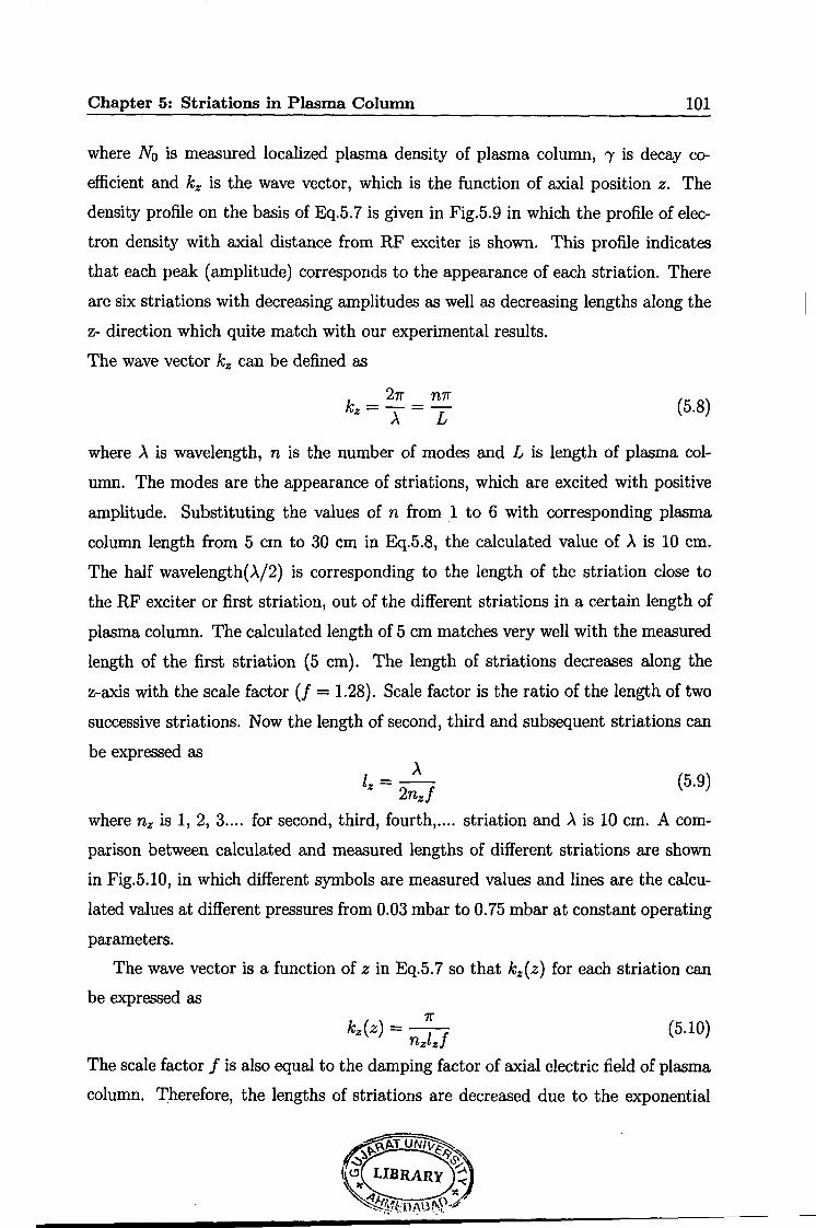
Chapter 5: Striations in Plasma Column 101
where N0 is measured localized plasma density of plasma column, 'Y is decay co
efficient and kz is the wave vector, which is the function of axial position z. The
density profile on the basis of Eq.5. 7 is given in Fig.5.9 in which the profile of elec
tron density with axial distance from RF exciter is shown. This profile indicates
that each peak (amplitude) corresponds to the appearance of each striation. There
are six striations with decreasing amplitudes as well as decreasing lengths along the
z- direction which quite match with our experimental results.
The wave vector kz can be defined as
k _ 21r _ n1r z-)..- L (5.8)
where ).. is wavelength, n is the number of modes and L is length of plasma col
umn. The modes are the appearance of striations, which are excited with positive
amplitude. Substituting the values of n from 1 to 6 with corresponding plasma
column length from 5 em to 30 em in Eq.5.8, the calculated value of ).. is 10 em.
The half wavelength(>../2) is corresponding to the length of the striation close to
the RF exciter or first striation, out of the different striations in a certain length of
plasma column. The calculated length of 5 em matches very well with the measured
length of the first striation (5 em). The length of striations decreases along the
z-axis with the scale factor (! = 1.28). Scale factor is the ratio of the length of two
successive striations. Now the length of second, third and subsequent striations can
be expressed as
(5.9)
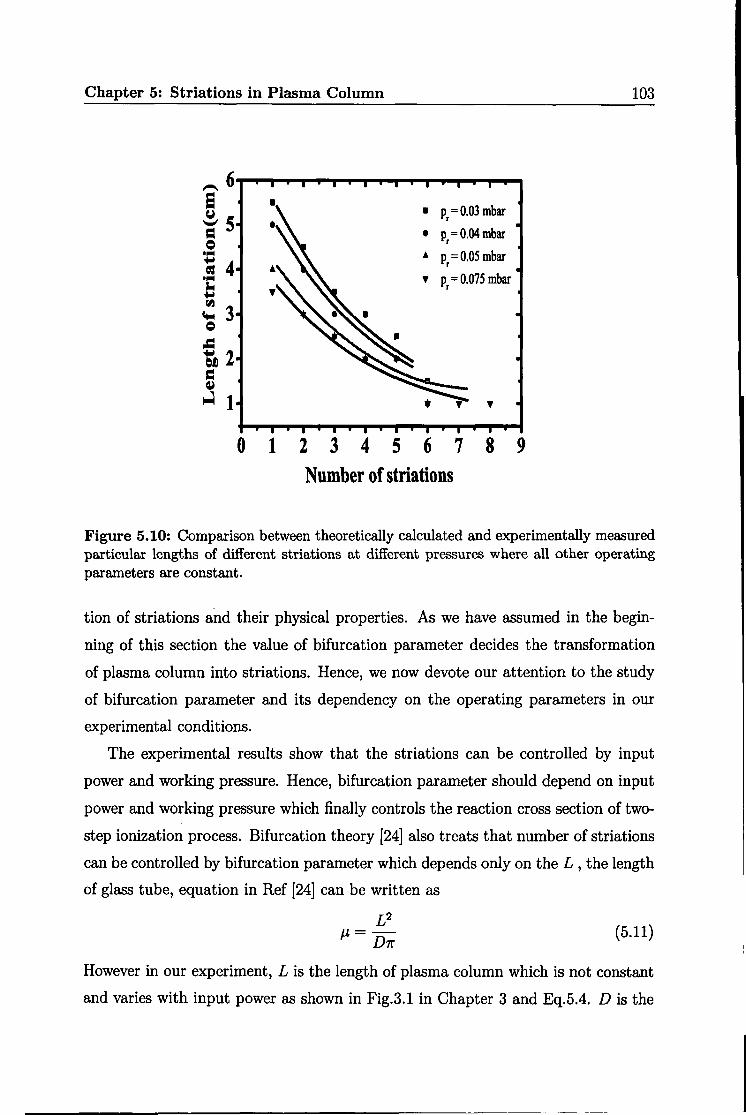
where nz is 1, 2, 3 .... for second, third, fourth, .... striation and ).. is 10 em. A com
parison between calculated and measured lengths of different striations are shown
in Fig.5.10, in which different symbols are measured values and lines are the calcu
lated values at different pressures from 0.03 mbar to 0.75 mbar at constant operating
parameters.
The wave vector is a function of z in Eq.5.7 so that kz(z) for each striation can
be expressed as 7r
kz(z) = - 1 f nz z (5.10)
The scale factor f is also equal to the damping factor of axial electric field of plasma
column. Therefore, the lengths of striations are decreased due to the exponential

Chapter 5: Striations in Plasma Column
0 5 10 15 20 25 30 Axial distance (em)
102
Figure 5.9: Plasma density profile of six striations along the axis of plasma column of length 30 em.
decay of axial electric field of surface wave in plasma column. This result emerges
our interest to study the electric field profiles with and without striations, which
can be compared with the plasma density profile.
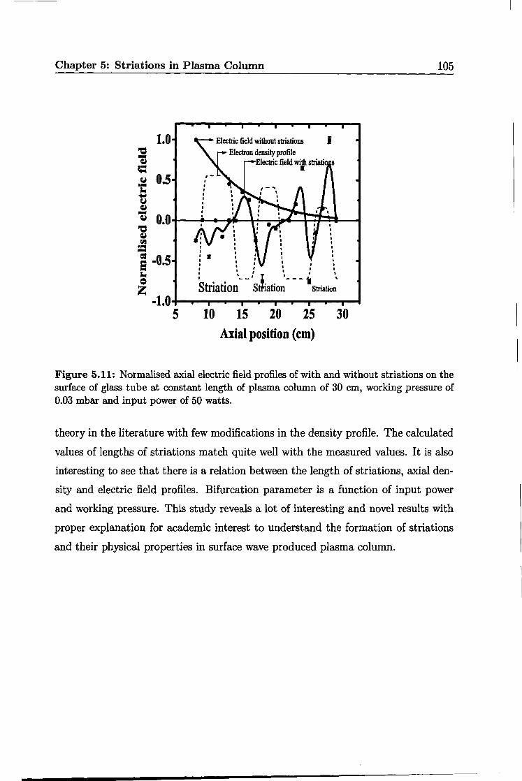
The electric field profiles on the surface of plasma column without striations and
with striations with comparison to density profile are shown in Fig.5.11, in which
solid line with circles shows axial electric field profile of plasma column without
striations, solid line with squares shows the axial electric field profile with striations
and dotted line shows the plasma density profile. From Fig.5.11, it can be shown
that electric field is negative, positive and zero for striations and if this profile is
compared to the profile of plasma density, then it is clear that, when plasma den
sity is higher, electric field is negative and axial distance is the length of particular
striation and when plasma density is minimum, electric field is positive where axial
distance is gap between two striations while electric field becomes zero at transit
region.
Till now, we have made an attempt to understand the discharge mechanism, forma-
Chapter 5: Striations in Plasma Column
• p = 0.03 mbar r
• p = 0.04 mbar r
• p = 0.05 mbar r
• p = 0.075 mbar r
0 1 2 3 4 5 6 7 8 9 Number of striations
103
Figure 5.10: Comparison between theoretically calculated and experimentally measured particular lengths of different striations at different pressures where all other operating parameters are constant.
tion of striations and their physical properties. As we have assumed in the begin
ning of this section the value of bifurcation parameter decides the transformation
of plasma column into striations. Hence, we now devote our attention to the study
of bifurcation parameter and its dependency on the operating parameters in our
experimental conditions.
The experimental results show that the striations can be controlled by input
power and working pressure. Hence, bifurcation parameter should depend on input
power and working pressure which finally controls the reaction cross section of two
step ionization process. Bifurcation theory [24] also treats that number of striations
can be controlled by bifurcation parameter which depends only on the L , the length
of glass tube, equation in Ref [24] can be written as
£2 J.L=
D1r (5.11)
However in our experiment, L is the length of plasma column which is not constant
and varies with input power as shown in Fig.3.1 in Chapter 3 and Eq.5.4. Dis the
Chapter 5: Striations in Plasma Column 104
diffusion coefficient of Argon gas. Number of stationary striations also vary with
length of plasma column (Fig.5.3). Length of particular striation decreases with
input power (Fig.5. 7) when 30 em long plasma column, number of striations and
working pressure are kept constant. It is because that the input power is func
tion of electric field and damping coefficient of this field is equal to the scale factor
of striations (Eq.5.9). The number of striations increases with working pressure
(Fig.5.5)and consequently length of striation decreases(Fig.5.6) because the neutral
density and plasma density are increased with working pressure. Therefore, bifur
cation parameter is a function of input power and working pressure which can be
written by putting the expression for L from Eq.5.4 in to Eq.5.11 then,
J1, = (7ra;8vm) :71" (5.12)
where a, Vm and D is constant for fixed diameter of glass tube, working pressure
and diffusion coefficient. This equation can be written as
J1, = it (Pr, a, D) P (5.13)
where
( 2 ) ! 1
it (pn a, D) = 1raB8vm D1r (5.14)
Thus the modified bifurcation theory can briefly explain the formation of striations
and their physical properties in the surface wave produced plasma column.
5. 7 Conclusions
Plasma column is formed with the help of radio frequency source operating be
tween 3 MHz to 10 MHz. By changing the operating parameters (input power from
40 watts to 60 watts and working pressure from 0.03 mbar to 0.30 mbar) plasma
column is transformed in to finite number of cylindrical stationary striations ( 4 to
12) in Argon gas due to the presence of metastable atoms for providing two-step
ionization. Number and length of striations can be controlled by changing working
pressure, input power and length of plasma column. A power balance equation is
modified for striations in surface wave produced plasma column. An attempt is
made to explain the lengths of different striations with the help of stable bifurcation
Chapter 5: Striations in Plasma Column
1.0
10
Electric field without striations I Electron density profile
Electric field with striatio I
15 20 25 Axial position (em)
105
30
Figure 5.11: Normalised axial electric field profiles of with and without striations on the surface of glass tube at constant length of plasma column of 30 em, working pressure of 0.03 mbar and input power of 50 watts.
theory in the literature with few modifications in the density profile. The calculated
values of lengths of striations match quite well with the measured values. It is also
interesting to see that there is a relation between the length of striations, axial den
sity and electric field profiles. Bifurcation parameter is a function of input power
and working pressure. This study reveals a lot of interesting and novel results with
proper explanation for academic interest to understand the formation of striations
and their physical properties in surface wave produced plasma column.
Bibliography
[1] S. Pfau, A. Rutscher and K. Wojaczek, Cont. Plasma Phys., 9, 333 (1969).
[2] D. Venzke, E. Hayess and k. Wojaczek, Cont. Plasma Phys., 6, 365 (1966).
[3] A. V. Nedospasov, Usp. Fiz. Nauk, 94, 439 (1968). [Sov. Phys. Usp., 11, 174
(1968).]
[4] L. Pekarek, Usp. Fiz. Nauk, 94, 463 (1968). [Sov. Phys. Usp., 11, 188 (1968).]
[5] L. D. Tsendin, Plasma Sources Sci. Technol., 4, 200 (1995).
[6] Yu. P. Raizer, The Physics of Gas Discharge, Nauka, Moscow (1987).
[7] Yu. V. Golubovaskii and S. U. Nismov, Tech. Phys., 41, 645 (1996).
[8] P. S. Landa, N. A. Miskinova andY. V. Ponomarev, Sov. Phy. Usp., 23, 813
(1980).
[9] I. M. Chapnik, J. Phys. D: Appli., 14, L121 (1981).
[10] Y. P. Raizer, Gas Discharge Physics, Springer-Verlag, Berlin (1991).
[11] A. J. Balloni, Plasma Phy. and Contro. Fusion, 30, 1659 (1988).
[12) S.M. A. Durrani, P. Vidaud and D. R. Hall, J. Plasma Physics, 58, 193 (1997).
[13] H. S. Robertson and L. C. Hawkins, Proc. of the Seventh International Con-
ference on Phenomena of Ionized Gases(gradevinska knjiga, Beograd, Yugoslvia,
1966) II, 640 (1966).
[14] Harry. S. Robertson and John J. Herring, Phys. Fluids, 12, 836 (1969).
[15] Y. Hoshi, H. Yoshida and Y.Tsutsui, J. Appli. Phys., 92, 5668 (2002).
[16) A. V. Gurevich, K. P. Zybin and A. V. Lukyanov, Phys. Rev. Letters, 75, 2622
(1995).
[17] J. Ouyang, F. He, S. Feng, J. Miao, J. Wang, C. Liu, Phys. Letter A, 360, 619
(2007).
[18] K. Ohe, A. Naito, T. Kimura and N. Iwama, Phy. Fluids, B 3, 3302 (1991).
[19] I. Grabec and S. Mandelj, Phys. Lett. A, 287, 105 (2001).
106

Chapter 5: Striations in Plasma Column 107
[20] 0. A. Nerushev, S. A. Novopashin, V. V. Radchenko and G. I. Sukhinin, JETP.
Lett., 66, 711 (1997).
[21] 0. A. Nerushev, S. A. Novopashin, V. V. Radchenko and G. I. Sukhinin, Plas.
Phys. Report, 26, 81 (2000).
[22] 0. A. Nerushev, S. A. Novopashin, V. V. Radchenko and G. I. Sukhinin and
V. V.Sukhovskii, Plas. Phys. Report, 29, 796 (2003).
[23] A. V. Fedoseev and G. I. Sukhinin, Plas. Phys. Report, 30, 1061 (2004).
[24] Ronald A. Goldstein, Manual A. Huerta and James C. Nearing, Phys. Fluids,
22, 231 (1979).
[25] M. Moisan and Z. Zakrzewski, J. Phy D:Appli. Phy., 24, 1025 (1991).
[26] M. Moisan, A. Shivarova and A. W. Trivelpiece, Plasma Physics, 24,
1331(1982).
[27] M. A. Lieberman and A. J. Lichtenberg, Principles of Plasma Discharge and
Material Processing, New York: Wiley, 443 (1994).
[28] C. M. Ferreira, J. Phys. D:Appli. Phys., 16, 1673 (1983).
(29] Z. Zakrzewski, J. Phys. D:Appli. Phys., 16, 171 (1983).
(30] A. Sola, J. Cotrino, A. Gamero and V. Colomer, J. Phys. D:Appli. Phys., 20,
1250 (1987).
(31] H. S. Robertson, Phys. Rev., 105, 368 (1957).