chapter one programming fundamentals - … · chapter 1. programming fundamentals 3 program editor:...
TRANSCRIPT

1C H A P T E R O N E
ProgrammingFundamentals
IN THIS CHAPTER
This chapter is a guide to general 6000 programming tasks. It is divided into these main topics:
• Motion Architect programming environment . . . . . . . . . . . . . . 2 • Restricted commands during motion.. . . . . . . . . . . . . . . . . . . 18• Command syntax .. . . . . . . . . . . . . . . . . . . . . . . . . . . . . . . . . . . . . . . . . . . . . . . . 3 • Using Variables .. . . . . . . . . . . . . . . . . . . . . . . . . . . . . . . . . . . . . . . . . . . . 18• Creating programs (program development scenario). . . . . . 8 • Program flow control . . . . . . . . . . . . . . . . . . . . . . . . . . . . . . . . . . . . . . 23• Storing programs.. . . . . . . . . . . . . . . . . . . . . . . . . . . . . . . . . . . . . . . . . . . . . . . . 12 • Program interrupts.......................................... 29• Executing programs .. . . . . . . . . . . . . . . . . . . . . . . . . . . . . . . . . . . . . . . . . . . . . 14 • Error handling .. . . . . . . . . . . . . . . . . . . . . . . . . . . . . . . . . . . . . . . . . . . . . . 30• Creating and executing a set-up program..................... 14 • Non-volatile memory (stand-alone products) . . . . . . . . . 33• Program Security.................................................. 15 • System performance considerations . . . . . . . . . . . . . . . . . . . . 33• Controlling execution – programs & command buffer . . . . 16
2 6000 Series Programmer's Guide
Motion & Control Motion Architect Programming Environment
Every 6000 Series controller is shipped with Motion Architect, a Windows-basedprogramming tool designed to simplify your programming efforts. The main features ofMotion Architect are briefly described below. For detailed user information, refer to theMotion Architect User Guide.
• Setup Module: Provides dialog boxes for you to select basic system setup parameters(I/O definitions, position feedback, etc.) and then automatically generates a fully-commented “setup program.”
• Editor Module: Create blocks or lines of 6000 controller code, or copy portions ofcode from previous files. You can save program editor files for later use in BASIC, C,etc., or in the terminal emulator or test panel.
• Terminal Module: Communicating directly with the 6000 controller, the terminalemulator allows you to type in and execute controller code and transfer code files to andfrom the 6000 controller.
• Panel Module: You can create your own test panel to run your programs and checkthe activity of I/O, motion, system status, etc. This can be invaluable during start-upsand when fine tuning machine performance.
• On-line Help and User Documentation: Under the Help menu, you will finduser information about Motion Architect, as well as interactive access to the contents ofthe 6000 Series Programmer's Guide (the document you are reading right now)and the 6000 Series Command Reference.
Add-on modules for Motion Architect are available to aide in other programming and set-uptasks. These modules are available through your local Automation Technology Center.
• Servo Tuner™: Tune your servo controller and the attached servo drives and receiveinstant data feedback on customizable displays. For detailed user information, refer to theServo Tuner User Guide.
• CompuCAM™: CompuCAM allows you to import 2D geometry from CADprograms (DXF), plotter files (HP-GL), or NC programs (G-Code), and then translate thegeometry into 6000 motion programs. These programs can be further edited in MotionArchitect's Program Editor module and dowloaded to the 6000 controller from theTerminal Emulator or Test Panel modules. A typical use of CompuCAM is to automatethe process for developing 6000 Series contouring code for an application. For detaileduser information, refer to the CompuCAM User Guide.
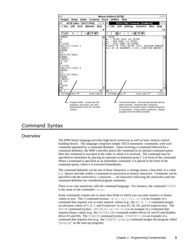
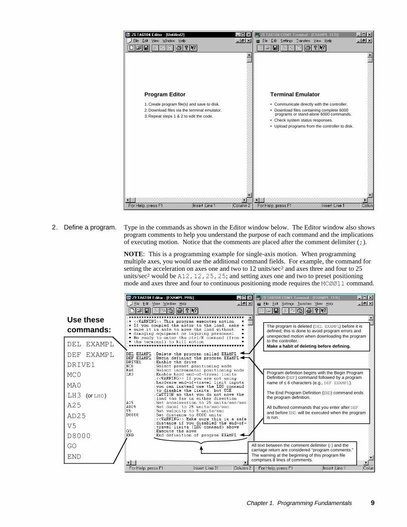
Side-by-Side Editor and Terminal Windows (see illustration below)
This side-by-sidetechnique isdemonstrated in theprogrammingscenario on page 8.
Typically, the programming process is an iterative exercise in which you create a program,test it, edit it, test it ... until you are satisfied with the results. To help with this iterativeprocess, we suggest using Motion Architect's Editor and Terminal modules in a side-by-sidefashion (open an Editor session and a Terminal session and re-size the windows so that youcan see both at the same time). In doing so you can quickly jump back and forth betweenediting a program (Editor function) and downloading it to the product and checkingprogramming responses and error messages (Terminal functions).
Chapter 1. Programming Fundamentals 3
Program Editor: Create and edit programs, save them, and then download them from the Terminal module.
Terminal Emulator: Communicate directly with the 6000 controller. Download files containing stand-alone commands and/or complete programs or subroutines. Check system responses. Upload programs from the 6000 controller.
Command Syntax
OverviewThe 6000 Series language provides high-level constructs as well as basic motion controlbuilding blocks. The language comprises simple ASCII mnemonic commands, with eachcommand separated by a command delimiter. Upon receiving a command followed by acommand delimiter, the 6000 controller places the command in its internal command queue.Here the command is executed in the order in which it is received. The command may bespecified as immediate by placing an optional exclamation point (!) in front of the command.When a command is specified as an immediate command, it is placed at the front of thecommand queue, where it is executed immediately.
The command delimiter can be one of three characters, a carriage return, a line-feed, or a colon(:). Spaces and tabs within a command are processed as neutral characters. Comments can bespecified with the semicolon (;) character — all characters following the semicolon until thecommand delimiter are considered program comments.
There is no case sensitivity with the command language. For instance, the command TSTATis the same as the command tstat.
Some commands contain one or more data fields in which you can enter numeric or binaryvalues or text. The A command (syntax: A<r>,<r>,<r>,<r>) is an example of acommand that requires you to enter numeric values (e.g., the A5,6,7,8 command assignsacceleration values of 5, 6, 7, and 8 units/sec2 to axes #1, #2, #3, and #4 respectively). TheDRIVE command (syntax: DRIVE<b><b><b><b>) is an example of a command thatrequires binary values (e.g., the DRIVE11ØØ command enables drives #1 and #2 and disablesdrives #3 and #4). The STARTP command (syntax: STARTP<t>) is an example of acommand that requires text (e.g., the STARTP powrup command assigns the program called“powrup” as the start-up program).

4 6000 Series Programmer's Guide
Description of Syntax Letters and SymbolsThe command descriptions provided within the 6000 Series Software Reference usealphabetic letters and ASCII symbols within the Synt ax description to represent differentparameter requirements (see example below).
INEN Input Enable
Syntax Symbology ☞Type Inputs or Program Debug ToolsSyntax <!>INEN<d><d><d>...<d>>Units d = Ø, 1, E, or XRange Ø = off, 1 = on, E = enable, X = don't changeDefault EResponse INEN: *INENEEEE_EEEE_EEEE_EEEE_EEEE_EEEE_EEEE
See Also [ IN ], INFEN, INFNC, INLVL, INPLC, INSTW, TIN
Product RevAT6n00 1.0AT6n50 1.0610n 1.0615n 1.0620n 1.0625n 1.06270 1.0
Letter /Symbol Description
a Represents an axis specifier, numeric value from 1 to 4 (used only to elicit aresponse from the indexer)
b* Represents the values 1,Ø, X or x; does not require field separator betweenvalues.
c Represents a character (A to Z, or a to z)
d Represents the values 1,Ø, X or x, E or e ; does not require field separatorbetween values. E or e enables a specific command field. X or x leaves thespecific command field unchanged or ignored.
i Represents a numeric value that cannot contain a decimal point (integer valuesonly). The numeric range varies by command. Field separator (,) required.
r Represents a numeric value that may contain a decimal point, but is not requiredto have a decimal point. The numeric range varies by command. Field separator(,) required.
t Represents a string of alpha numeric characters from 1 to 6 characters in length.The string must start with an alpha character.
! Represents an immediate command. Changes a buffered command to animmediate command. Immediate commands are processed immediately, evenbefore previously entered buffered commands.
, Represents a field separator. Commands with the symbol r or i in their Synt axdescription require field separators. Commands with the symbol b or d in theirSynt ax description do not require field separators (but they may be included).See General Guidelines table below for more information.
@ Represents a global specifier, where only one field need be entered. Applicableto all commands with multiple command fields. (e.g., @V1 sets velocity on allaxes to 1 rps)
< > Indicates that the item contained within the < > is optional, not required by thatcommand. NOTE: Do not confuse with <cr>, <sp>, and <lf>, which refer to theASCII characters corresponding to a carriage return, space, and line feed,respectively.
[ ] Indicates that the command between the [ ] must be used within the syntax ofanother command, and cannot be used by itself.
* The ASCII character b can also be used within a command to precede a binary number. When the b isused in this context, it is not to be replaced with a Ø, 1, X, or x. Examples are assignments such asVARB1=b1ØØØ1, and comparisons such as IF(IN=b1ØØ1X1).
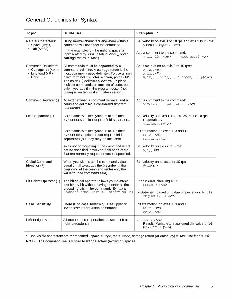
Chapter 1. Programming Fundamentals 5
General Guidelines for Syntax
Topic Guideline Examples *
Neutral Characters:• Space (<sp>)• Tab (<tab>)
Using neutral characters anywhere within acommand will not affect the command.
(In the examples on the right, a space isrepresented by <sp>, a tab is <tab>), and acarriage return is <cr>.)
Set velocity on axis 1 to 10 rps and axis 2 to 25 rps:V<sp>1Ø,<sp>25,,<cr>
Add a comment to the command:V 1Ø, 25,,<tab> ;set accel <cr>
Command Delimiters:• Carriage rtn (<cr>)• Line feed (<lf>)• Colon (:)
All commands must be separated by acommand delimiter. A carriage return is themost commonly used delimiter. To use a line ina live terminal emulator session, press ctrl/J.The colon (:) delimiter allows you to placemultiple commands on one line of code, butonly if you add it in the program editor (notduring a live terminal emulator session).
Set acceleration on axis 2 to 10 rps2:A,1Ø,,<cr>A,1Ø,,<lf>A,1Ø,, : V,25,, : D,25ØØØ,, : @GO<cr>
Comment Delimiter (;) All text between a comment delimiter and acommand delimiter is considered programcomments.
Add a comment to the command:V1Ø<tab> ;set velocity<cr>
Field Separator (,) Commands with the symbol r or i in theirSynt ax description require field separators.
Commands with the symbol b or d in theirSynt ax description do not require fieldseparators (but they may be included).
Axes not participating in the command neednot be specified; however, field separatorsthat are normally required must be specified.
Set velocity on axes 1-4 to 10, 25, 5 and 10 rps,respectively:V1Ø,25,5,1Ø<cr>
Initiate motion on axes 1, 3 and 4:GO1Ø11<cr>GO1,Ø,1,1<cr>
Set velocity on axis 2 to 5 rps:V,5,,<cr>
Global CommandIdentifier (@)
When you wish to set the command valueequal on all axes, add the @ symbol at thebeginning of the command (enter only thevalue for one command field).
Set velocity on all axes to 10 rps:@V1Ø<cr>
Bit Select Operator (.) The bit select operator allows you to affectone binary bit without having to enter all thepreceding bits in the command. Syntax is[command name].[bit #]-[binary value]
Enable error-checking bit #9:ERROR.9-1<cr>
IF statement based on value of axis status bit #12:IF(1AS.12=b1)<cr>
Case Sensitivity There is no case sensitivity. Use upper orlower case letters within commands.
Initiate motion on axes 1, 3 and 4:GO1Ø11<cr>go1Ø11<cr>
Left-to-right Math All mathematical operations assume left-to-right precedence.
VAR1=5+3*2<cr>Result: Variable 1 is assigned the value of 16(8*2), not 11 (5+6).
* Non-visible characters are represented: space = <sp>, tab = <tab>, carriage return (or enter key) = <cr>, line feed = <lf>.
NOTE: The command line is limited to 80 characters (excluding spaces).

6 6000 Series Programmer's Guide
Command Value SubstitutionsMany commands can have a variable name (VAR), a binary variable name (VARB), a datacommand (DAT), a read command (READ, DREAD, or DREADF), or a thumbwheel value (TW)substituted for the command value. The substitution must be enclosed in parentheses.
Substitution Description
VAR Current value of the numeric variable is placed in the corresponding field of the command
VARB Value of the binary variable is used to establish all the fields in the command
DAT Current value of the data program (DATP) is placed in the corresponding field of the command
READ Information is requested at the time the command is executed
DREAD Read the RP240's numeric keypad into the corresponding field of the command
DREADF Read the RP240's function keypad into the corresponding field of the command
TW Current value set on the thumbwheels is placed in the corresponding field of the command
N O T ENot all of the commands allow this type of substitution for the values in their command fields.For a complete list of the commands and the possible substitutions, refer to Appendix C inthe 6000 Series Software Reference.
Example D escrip t ion> VAR1=15 Set variable 1 to 15> A5,(VAR1),4,4 Set acceleration to 5,15,4,4 for axes 1 - 4, respectively
(numeric value of variable 1 is substituted as the accel valuefor axis 2)
> VARB1=b1101XX1 Set binary variable 1 to 1101XX1 (bits 5 & 6 are not affected)> GO(VARB1) Initiate motion on the axes specified by binary variable 1 (in
this example, axes 1, 2, and 4)> OUT(VARB1) Turn on outputs 1, 2, 4, and 7; turn off output 3
> VARS1="Enter Velocity" Set string variable 1 equal to the message "Enter Velocity"> V2,(READ1) Set the velocity to 2 on axis 1. Substitute the velocity entered
by the user as the velocity value for axis 2, output variablestring 1 as the prompting message to the user.
ENTER VELOCITY Operator prompt message> !'20 Value entered by operator is 20; thus, axis 2 velocity is 20
> HOMV2,1,(TW1) Set the home velocity to 2 and 1 on axes 1 and 2, respectively.Read in the home velocity for axis 3 from thumbwheel set 1
> HOMV2,1,(DAT1) Set the home velocity to 2 and 1 on axes 1 and 2, respectively.Read home velocity for axis 3 from data program 1.
Assignment and Comparison OperatorsComparison and assignment operators are used in command arguments for various functionssuch as variable assignments, conditional branches, wait statements, conditional GOs, etc.Some examples are listed below:
• Assign to numeric variable #6 the value of the encoder position on axis #3 (uses the PEoperator): VAR6=3PE
• Wait until inputs #3 & #6 become active (uses the IN operator): WAIT(IN=bxx1xx1)
• Continue until the value of numeric variable #2 is less than 36: UNTIL(VAR2<36)
• IF condition based on if a target zone timeout occurs on axis 2 (uses the AS axis statusoperator, where status bit #25 is set if a target zone timeout occurs): IF(2AS.25=b1)
The available comparison and assignment operators are listed below. For full descriptions,refer to their respective descriptions in the 6000 Series Software Reference(be sure to refer only to the commands in brackets—e.g., A is the acceleration setup command,but [ A ] is the acceleration assignment/comparison operator).
Chapter 1. Programming Fundamentals 7
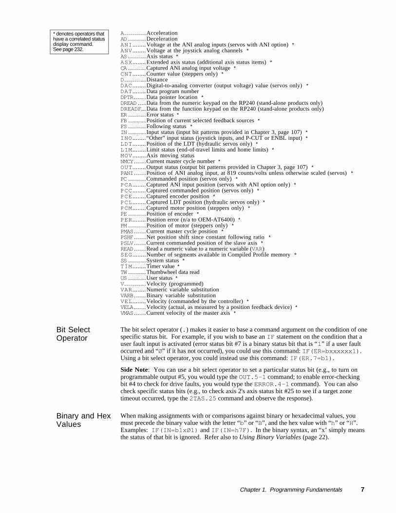
* denotes operators thathave a correlated statusdisplay command.See page 232.
A. . . . . . . . . . . AccelerationAD . . . . . . . . . DecelerationANI ........ Voltage at the ANI analog inputs (servos with ANI option) *ANV ........ Voltage at the joystick analog channels *AS . . . . . . . . . Axis status *ASX ........ Extended axis status (additional axis status items) *CA . . . . . . . . . Captured ANI analog input voltage *CNT ........ Counter value (steppers only) *D. . . . . . . . . . . DistanceDAC ........ Digital-to-analog converter (output voltage) value (servos only) *DAT ........ Data program numberDPTR . . . . . . Data pointer location *DREAD . . . . Data from the numeric keypad on the RP240 (stand-alone products only)DREADF... Data from the function keypad on the RP240 (stand-alone products only)ER . . . . . . . . . Error status *FB . . . . . . . . . Position of current selected feedback sources *FS . . . . . . . . . Following status *IN . . . . . . . . . Input status (input bit patterns provided in Chapter 3, page 107) *INO ........ “Other” input status (joystick inputs, and P-CUT or ENBL input) *LDT ........ Position of the LDT (hydraulic servos only) *LIM ........ Limit status (end-of-travel limits and home limits) *MOV ........ Axis moving statusNMCY . . . . . . Current master cycle number *OUT ........ Output status (output bit patterns provided in Chapter 3, page 107) *PANI . . . . . . Position of ANI analog input, at 819 counts/volts unless otherwise scaled (servos) *PC . . . . . . . . . Commanded position (servos only) *PCA ........ Captured ANI input position (servos with ANI option only) *PCC ........ Captured commanded position (servos only) *PCE ........ Captured encoder position *PCL ........ Captured LDT position (hydraulic servos only) *PCM ........ Captured motor position (steppers only) *PE . . . . . . . . . Position of encoder *PER ........ Position error (n/a to OEM-AT6400) *PM . . . . . . . . . Position of motor (steppers only) *PMAS . . . . . . Current master cycle position *PSHF . . . . . . Net position shift since constant following ratio *PSLV . . . . . . Current commanded position of the slave axis *READ . . . . . . Read a numeric value to a numeric variable (VAR)SEG ........ Number of segments available in Compiled Profile memory *SS . . . . . . . . . System status *TIM ........ Timer value *TW . . . . . . . . . Thumbwheel data readUS . . . . . . . . . User status *V. . . . . . . . . . . Velocity (programmed)VAR ........ Numeric variable substitutionVARB . . . . . . Binary variable substitutionVEL ........ Velocity (commanded by the controller) *VELA . . . . . . Velocity (actual, as measured by a position feedback device) *VMAS . . . . . . Current velocity of the master axis *
Bit SelectOperator
The bit select operator (.) makes it easier to base a command argument on the condition of onespecific status bit. For example, if you wish to base an IF statement on the condition that auser fault input is activated (error status bit #7 is a binary status bit that is “1” if a user faultoccurred and “Ø” if it has not occurred), you could use this command: IF(ER=bxxxxxx1).Using a bit select operator, you could instead use this command: IF(ER.7=b1).
Side Note: You can use a bit select operator to set a particular status bit (e.g., to turn onprogrammable output #5, you would type the OUT.5-1 command; to enable error-checkingbit #4 to check for drive faults, you would type the ERROR.4-1 command). You can alsocheck specific status bits (e.g., to check axis 2's axis status bit #25 to see if a target zonetimeout occurred, type the 2TAS.25 command and observe the response).
Binary and HexValues
When making assignments with or comparisons against binary or hexadecimal values, youmust precede the binary value with the letter “b” or “B”, and the hex value with “h” or “H”.Examples: IF(IN=b1xØ1) and IF(IN=h7F). In the binary syntax, an “x’ simply meansthe status of that bit is ignored. Refer also to Using Binary Variables (page 22).

8 6000 Series Programmer's Guide
RelatedOperatorSymbols
Command arguments include special operator symbols (e.g., +, /, &, ', >=, etc.) to performbitwise, mathematical, relational, logical, and other special functions. These operators aredescribed in detail, along with programming examples, at the beginning of the CommandDescriptions section of the 6000 Series Software Reference.
Programmable Inputs and Outputs Bit Patterns
I/O pin outs,specifications, andcircuit drawings areprovided in each 6000Series product'sinstallation guide.
The total number of inputs and outputs (I/O) varies from one 6000 Series product to another.Consequently, bit patterns for the programmable I/O also vary by product. For example, theAT6400's TRG-A trigger input is represented by programmable input bit #25, but the 6104'sTRG-A trigger input is bit #17. Bit numbers are referenced in commands likeWAIT(IN.13=b1), which means wait until programmable input #13 becomes active. Toascertain your product's I/O offering and bit patterns, refer to Chapter 3 (page 107).
Creating Programs
A program is a series of commands. These commands are executed in the order in which theyare programmed. Immediate commands (commands that begin with an exclamation point [!])cannot be stored in a program. Only buffered commands may be used in a program.
Debugging Programs:Refer to page 231 formethods to isolate andresolve programmingproblems.
A subroutine is defined the same as a program, but it is executed with an unconditional branchcommand, such as GOSUB, GOTO, or JUMP, from another program (see page 23 for detailsabout unconditional branching). Subroutines can be nested up to 16 levels deep. NOTE: The6000 family does not support recursive calling of subroutines.
Another kind of program is a compiled profile. Compiled profiles are defined like programs(using the DEF and END commands), but are compiled with the PCOMP command and executedwith the PRUN command. A compiled profile could be a multi-axis contour (a series of arcsand lines), an individual axis profile (a series of GOBUF commands), or a compound profile(combination of multi-axis contours and individual axis profiles). For more information oncontours, refer to Contouring in Chapter 5, page 153. For more information on compiledindividual axis profiles, refer to Compiled Motion Profiling in Chapter 5, page 163.
Program Development ScenarioTo best understand the process of developing 6000 programs, we invite you to follow alongon a program development scenario. The scenario covers these programming tasks:
1. Set up the programming environment (using Motion Architect's Editor and Terminal).2. Create a simple motion program in the Editor.3. Download the program, via the Terminal, to the controller.4. Execute (run) the program from the Terminal.5. Edit the program, redownload it, and run it again.
1. Set up MotionArchitect.
Typically, the programming process is an iterative exercise in which you create a program,test it, edit it, test it ... until you are satisfied with the results. To help with this iterativeprocess, we suggest using Motion Architect's Editor and Terminal modules in a side-by-sidefashion (open an Editor session and a Terminal session and re-size the windows so that youcan see both at the same time). In doing so you can quickly jump back and forth betweenediting a program (Editor function) and downloading it to the product and checkingprogramming responses and error messages (Terminal functions).
Chapter 1. Programming Fundamentals 9
Program Editor
1. Create program file(s) and save to disk.
2. Download files via the terminal emulator.
3. Repeat steps 1 & 2 to edit the code.
Terminal Emulator
• Communicate directly with the controller.
• Download files containing complete 6000 programs or stand-alone 6000 commands.
• Check system status responses.
• Upload programs from the controller to disk.
2. Define a program. Type in the commands as shown in the Editor window below. The Editor window also showsprogram comments to help you understand the purpose of each command and the implicationsof executing motion. Notice that the comments are placed after the comment delimiter (;).
NOTE: This is a programming example for single-axis motion. When programmingmultiple axes, you would use the additional command fields. For example, the command forsetting the acceleration on axes one and two to 12 units/sec2 and axes three and four to 25units/sec2 would be A12,12,25,25; and setting axes one and two to preset positioningmode and axes three and four to continuous positioning mode requires the MCØØ11 command.
The program is deleted (DEL EXAMPL) before it isdefined; this is done to avoid program errors andunexpected motion when downloading the programto the controller.Make a habit of deleting before defining.
Program definition begins with the Begin ProgramDefinition (DEF ) command followed by a programname of ≤ 6 characters (e.g., DEF EXAMPL).
The End Program Definition (END) command endsthe program definition.
All buffered commands that you enter after DEFand before END will be executed when the programis run.
Use thesecommands:
DEL EXAMPL
DEF EXAMPLDRIVE1MC0
MA0LH3 (or LH0)
A25
AD25V5D8000GO
END
All text between the comment delimiter (;) and thecarriage return are considered “program comments.”The warning at the beginning of this program filecomprises 8 lines of comments.

1 0 6000 Series Programmer's Guide
3. Download theprogram.
FIRST: Before you can download the program, youmust save it to your hard drive (select File/Save in theEditor). The file is saved with a “.PRG” extension. Inthe Save dialog box, name the file “EXAMPL.PRG”.
Follow these steps to download the program file to thecontroller:
1. Power up the controller. Notice the power-upmessage (like the one shown below) display in yourterminal emulator window.
Save the program first (Editor).
2. From the Transfers menu in the Terminal window,select Send Motion Program(s). From the dialog box,select the EXAMPL.PRG file and click OK. The firsttime you download the file, you will see two messagesdisplay: “*UNDEFINED LABEL” and ”DELEXAMPL”(on subsequent downloads of the same file, you wouldinstead see the message “NO ERRORS”).
Download the program (Terminal).
TIP: If the controller is executing a program when you try to download a programfile, the program(s) from the program file will not download and the contents of theprogram(s) will be displayed to the terminal emulator window. To prevent this error,“kill” program execution (and motion) before downloading the program file — usethe !K command or the ctrl/K command (ctrl/K is an easier keystroke combination).
3. To verify that the EXAMPL program resides in the controller's memory, type the TDIRcommand and press the carriage return or enter key.
Power-up message for the ZETA6104controller.
Messages for first-time download(subsequent download will yield themessage “NO ERRORS”).
The TDIR status command yields a3-line response. The first line showsthe the EXAMPL program resides inmemory and uses 50 bytes. Thesecond line shows the status ofmemory available for programstorage (this is where EXAMPL isstored). The third line shows thestatus of memory available to storecompiled motion profiles (programscompiled with the PCOMP command).
Chapter 1. Programming Fundamentals 1 1
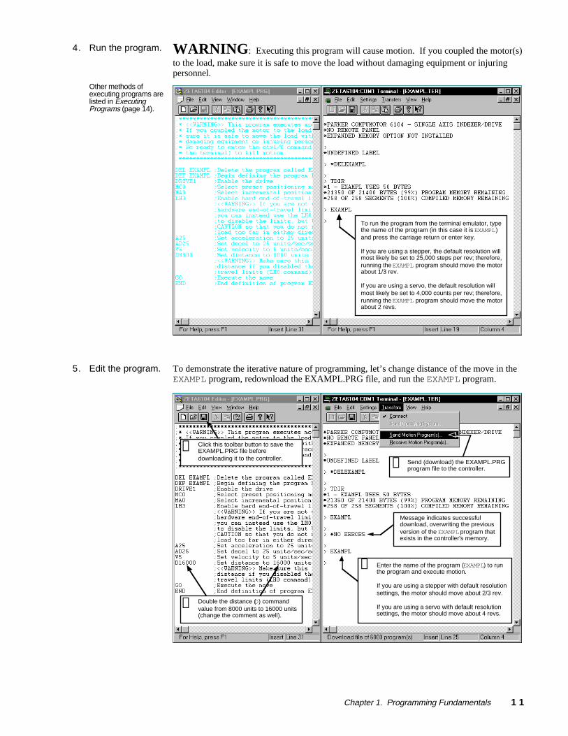
4. Run the program.
Other methods ofexecuting programs arelisted in ExecutingPrograms (page 14).
WARNING: Executing this program will cause motion. If you coupled the motor(s)to the load, make sure it is safe to move the load without damaging equipment or injuringpersonnel.
To run the program from the terminal emulator, typethe name of the program (in this case it is EXAMPL)and press the carriage return or enter key.
If you are using a stepper, the default resolution willmost likely be set to 25,000 steps per rev; therefore,running the EXAMPL program should move the motorabout 1/3 rev.
If you are using a servo, the default resolution willmost likely be set to 4,000 counts per rev; therefore,running the EXAMPL program should move the motorabout 2 revs.
5. Edit the program. To demonstrate the iterative nature of programming, let’s change distance of the move in theEXAMPL program, redownload the EXAMPL.PRG file, and run the EXAMPL program.
Enter the name of the program (EXAMPL) to runthe program and execute motion.
If you are using a stepper with default resolutionsettings, the motor should move about 2/3 rev.
If you are using a servo with default resolutionsettings, the motor should move about 4 revs.
Message indicates successfuldownload, overwriting the previousversion of the EXAMPL program thatexists in the controller's memory.
➃
Double the distance (D) commandvalue from 8000 units to 16000 units(change the comment as well).
➀
Click this toolbar button to save theEXAMPL.PRG file beforedownloading it to the controller.
➁Send (download) the EXAMPL.PRGprogram file to the controller.➂

1 2 6000 Series Programmer's Guide
Storing Programs
Programs and compiled profiles are stored in the controller's memory (non-volatile memoryfor stand-alone products and volatile memory for bus-based products). Information oncontrolling memory allocation is provided below (see Memory Allocation).
Storing Programs in Stand-Alone ProductsIf you are using a stand-alone (serial interface) product, programs and compiled profiles areautomatically stored in non-volatile memory (battery-backed RAM).
More information on other items that are stored in non-volatile memory is provided below.
Storing Programs in Bus-Based ProductsIf you are using a bus-based product, programsand compiled profiles are stored in volatileRAM memory (not battery-backed). Therefore,you should backup your motionprograms to your computer's hard disk orfloppy disk to ensure their safety. This iseasily done with the Receive Motion Programfunction of Motion Architect's TerminalEmulator module (see diagram at right).
In general, your programs may already be stored on your computer, since most programs arecreated with Motion Architect's Editor or with the 6000 DOS support software package (seeProgram Development Scenario starting on page 8).
Application set-up parameters such as drive setup, feedback setup, I/O configuration, etc.,should be placed in a set-up program that is called/downloaded and executed before performingany other controller functions (see Creating and Executing a Set-Up Program on page 14).
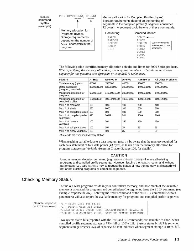
Memory AllocationYour controller's memory has two partitions: one for storing programs and one for storingcompiled profiles. The allocation of memory to these two areas is controlled with theMEMORY command.
“Programs” vs. ”Compiled Profiles”
Programs are defined with the DEF and END commands, as demonstrated in the ProgramDevelopment Scenario starting on page 8.
Compiled Profiles are defined like programs (using the DEF and END commands), but arecompiled with the PCOMP command and executed with the PRUN command. Acompiled profile could be a multi-axis contour (a series of arcs and lines), anindividual axis profile (a series of GOBUF commands), or a compound profile(combination of multi-axis contours and individual axis profiles).
Programs intended to be compiled are stored in program memory. After they arecompiled with the PCOMP command, they remain in program memory and thesegments (see diagram below) from the compiled profile are stored in compiledmemory. The TDIR command reports which programs are compiled as a compiledprofile (referred to here as a path ).
For more information on multi-axis contours, refer to Contouring in Chapter 5, page153. For more information on compiled profiles for individual axes, refer to CompiledMotion Profiling in Chapter 5, page 163.
Chapter 1. Programming Fundamentals 1 3
MEMORYcommand
syntax(example)
MEMORY8ØØØØ,7ØØØØ Memory allocation for Compiled Profiles (bytes).Storage requirements depend on the number ofsegments in the compiled profile (1 segment consumes72 bytes). A segment could be one of these commands:
Memory allocation forPrograms (bytes).Storage requirementsdepend on the number ofASCII characters in theprogram.
PARCMPARCOMPARCOPPARCPPLIN
Contouring: Compiled Motion:
GOBUFPLOOPGOWHENTRGFNPOUTAPOUTBPOUTCPOUTD
GOBUF commandsmay require up to 4segments.
The following table identifies memory allocation defaults and limits for 6000 Series products.When specifying the memory allocation, use only even numbers. The minimum storagecapacity for one partition area (program or compiled) is 1,000 bytes.
Feature AT6n00 AT6n00-M AT6n50 AT6n50-M All Other Products
Total memory (bytes) 64000 1500000 40000 150000 150000Default allocation(program,compiled)
33000,31000 63000,1000 39000,1000 149000,1000 149000,1000
Maximum allocation forprograms
63000,1000 1499000,1000 39000,1000 149000,1000 149000,1000
Maximum allocation forcompiled profiles
1000,63000 1000,1499000 1000,39000 1000,149000 1000,149000
Max. # of programs 150 4000 100 400 400Max. # of labels 250 6000 100 600 600Max. # of compiled profiles 100 800 100 300 300Max. # of compiled profilesegments
875 20819 541 2069 2069
Max. # of numericvariables
100 200 150 150 150
Max. # of string variables 100 100 25 25 25Max. # of binary variables 100 100 25 25 25
-M refers to the Expanded Memory Option
When teaching variable data to a data program (DATP), be aware that the memory required foreach data statement of four data points (43 bytes) is taken from the memory allocation forprogram storage (see Variable Arrays in Chapter 3, page 120, for details).
CAUTIONUsing a memory allocation command (e.g., MEMORY39ØØØ,1ØØØ) will erase all existingprograms and compiled profile segments. However, issuing the MEMORY command withoutparameters (i.e., type MEMORY <cr> to request the status of how the memory is allocated) willnot affect existing programs or compiled segments.
Checking Memory StatusTo find out what programs reside in your controller's memory, and how much of the availablememory is allocated for programs and compiled profile segments, issue the TDIR command (seeexample response below). Entering the TMEM command or the MEMORY command (withoutparameters) will also report the available memory for programs and compiled profile segments.
Sample responseto TDIR command
*1 - SETUP USES 345 BYTES*2 - PIKPRT USES 333 BYTES*32322 OF 33000 BYTES (98%) PROGRAM MEMORY REMAINING*500 OF 500 SEGMENTS (100%) COMPILED MEMORY REMAINING
Two system status bits (reported with the TSS and SS commands) are available to check whencompiled profile segment storage is 75% full or 100% full. System status bit #29 is set whensegment storage reaches 75% of capacity; bit #30 indicates when segment storage is 100% full.
1 4 6000 Series Programmer's Guide
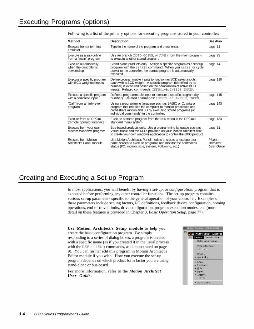
Executing Programs (options)
Following is a list of the primary options for executing programs stored in your controller:
Method Description See Also
Execute from a terminalemulator
Type in the name of the program and press enter. page 11
Execute as a subroutinefrom a “main” program
Use an branch (GOTO, GOSUB, or JUMP) from the main programto execute another stored program.
page 23
Execute automaticallywhen the controller ispowered up
Stand-alone products only. Assign a specific program as a startupprogram with the STARTP command. When you RESET or cyclepower to the controller, the startup program is automaticallyexecuted.
page 14
Execute a specific programwith BCD weighted inputs
Define programmable inputs to function as BCD select inputs,each with a BCD weight. A specific program (identified by itsnumber) is executed based on the combination of active BCDinputs. Related commands: INFNCi-B, INSELP, INFEN.
page 110
Execute a specific programwith a dedicated input
Define a programmable input to execute a specific program (bynumber). Related commands: INFNCi-iP, INSELP, INFEN.
page 115
“Call” from a high-levelprogram
Using a programming language such as BASIC or C, write aprogram that enables the computer to monitor processes andorchestrate motion and I/O by executing stored programs (orindividual commands) in the controller.
page 143
Execute from an RP240(remote operator interface)
Execute a stored program from the RUN menu in the RP240'sstandard menu system.
page 134
Execute from your owncustom Windows program
Bus-based products only. Use a programming language such asVisual Basic and the DLLs provided on your Motion Architect diskto create your own windows application to control the 6000 product.
page 51
Execute from MotionArchitect's Panel module
Use Motion Architect's Panel module to create a test/operatorpanel screen to execute programs and monitor the controller'sstatus (I/O, motion, axis, system, Following, etc.)
MotionArchitectUser Guide
Creating and Executing a Set-up Program
In most applications, you will benefit by having a set-up, or configuration, program that isexecuted before performing any other controller functions. The set-up program containsvarious set-up parameters specific to the general operation of your controller. Examples ofthese parameters include scaling factors, I/O definitions, feedback device configuration, homingoperations, end-of-travel limits, drive configuration, program execution modes, etc. (moredetail on these features is provided in Chapter 3, Basic Operation Setup, page 77).
Use Motion Architect's Setup module to help youcreate the basic configuration program. By simplyresponding to a series of dialog boxes, a program is createdwith a specific name (as if you created it in the usual processwith the DEF and END commands, as demonstrated on page9). You can further edit this program in Motion Architect'sEditor module if you wish. How you execute the set-upprogram depends on which product form factor you are using:stand-alone or bus-based.
For more information, refer to the Motion ArchitectUser Guide.

Chapter 1. Programming Fundamentals 1 5
Set-up Program Execution for Stand-Alone ControllersIf you created the set-up program in Motion Architect's Editor, you need to download it to the6000 controller's non-volatile memory via the Terminal Emulator module (see Send MotionProgram under the Transfers menu). If you created the set-up program in the terminalemulator, as in the example below, it is already stored to non-volatile memory.
Now that the set-up program is available, you can cause it to be executed automatically afterthe 6000 controller is powered-up or reset. To do this, you must assign it as the power-upstart program with the STARTP command (see fourth line in example below).
Example DEF setup ; Define program setupTREV ; Report software revisionEND ; End of program setupSTARTP setup ; Define program pwrup as the power-up programRESET ; Reset the controller; After reset, you should see a message like this:; *PARKER COMPUMOTOR 6201 MOTION CONTROLLER; *NO REMOTE PANEL
If the program that is identified as the STARTP program is deleted by the DEL command, theSTARTP is automatically cleared. If you wish to prevent the assigned STARTP program frombeing executed, without having to delete the program, issue the STARTP CLR command.
Set-up Program Execution for Bus-Based ControllersIn most cases you will require the parameters in the setup program to be executed as soon aspossible so that subsequent parameters are based on the setup program. This can be done usingMotion Architect. A set up program can be defined (in Motion Architect’s Setup Module),saved, and then downloaded in the Terminal Module (see Send Motion Program under theTransfers Menu). Once the setup program has been stored in the controller, it may be run byissuing the name of the setup program.
An alternative method would be to not store the setup parameters in a setup program, but havethem execute upon downloading to the controller. This can be done be defining the setupparameters in the Setup Module of Motion Architect, but not specifying a setup program.This will remove the DEF and END statements from the setup file, which you will downloadthe same way in Motion Architect’s Terminal Module. Because the statements execute upondownloading, there is no need to issue a program name.
Program Security
Issuing the INFNCi-Q command enables the Program Security feature and assigns theProgram Access function to the specified programmable input. The “i” represents the numberof the programmable input to which you wish to assign the function.
The program security feature denies you access to the DEF, DEL, ERASE, MEMORY, andINFNC commands until you activate the program access input. Being denied access to thesecommands effectively restricts altering the user memory allocation. If you try to use thesecommands when program security is active (program access input is not activated), you willreceive the error message *ACCESS DENIED.
For example, once you issue the INFNC22-Q command, input #22 is assigned the programaccess function and access to the DEF, DEL, ERASE, MEMORY, and INFNC commands willbe denied until you activate input #22.
To regain access to these commands without the use of the program access input, you mustissue the INFENØ command to disable programmable input functions, make the required usermemory changes, and then issue the INFEN1 command to re-enable the programmable inputfunctions.

1 6 6000 Series Programmer's Guide
Controlling Execution of Programs and the Command Buffer
The 6000 controller command buffer is capable of storing 2000 characters waiting to beprocessed. (This is separate from the memory allocated for program storage – see MemoryAllocation, page 12.) Three commands, COMEXC, COMEXK, and COMEXP, affect commandexecution. Three additional commands, COMEXL, COMEXR, and COMEXS, affect theexecution of programs and the command buffer.
COMEXC (Continuous Command Execution)
The COMEXC command enables the Continuous Command Execution Mode. This modeallows the program to continue to the next command before motion is complete. This isuseful for:
• Monitoring other processes while motion is occurring
• Performing calculations in advance of motion completion
• Pre-emptive GOs — executing a new profile with new attributes (distance, accel/decel,velocity, positioning mode, and Following ratio ) before motion is complete: Themotion profile underway is pre-empted with a new profile when a new GO is issued. Thenew GO both constructs and launches the pre-empting profile. Pre-emptive GOs areappropriate when the desired motion parameters are not known until motion is alreadyunderway. For a detailed description, refer to On-The-Fly Motion on page 178.
• Pre-process the next move while the current move is in progress (see CAUTION note).This reduces the processing time for the subsequent move to only a few microseconds.
CAUTION: Avoid executing moves prematurely
With continuous command execution enabled (COMEXC1), if you wish motion to stopbefore executing the subsequent move, place a WAIT(AS.1=bØ) statement before thesubsequent GO command. If you wish to ensure the load settles adequately before thenext move, use the WAIT(AS.24=b1) command instead (this requires you to defineend-of-move settling criteria — see Target Zone Mode on page 105 for details).
In the programming example below, by enabling the continuous command execution mode(COMEXC1), the controller is able to turn on output #3 after the encoder moves 4000 units ofits 125000-unit move. Normally, with COMEXC disabled (COMEXCØ), command processingwould be temporarily stopped at the GO1 command until motion is complete.
Programming Example (portion of program only)
COMEXC1 ;Enable continuous command execution modeD125000 ;Set distanceV2 ;Set velocityA10 ;Set accelerationGO1 ;Initiate motion on axis 1WAIT(1PE>4000) ;Wait for the encoder position to exceed 4000OUTXX1 ;Turn on programmable output #3WAIT(AS.1=b0) ;Wait for motion to complete on axis 1 (AS bit #1 = zero)OUTXX0 ;Turn off programmable output #3
COMEXK (Continue Command Execution on Kill)
This feature is applicable only to bus-based products. The COMEXK commanddetermines whether the commands following a Kill (K) command in a block write will be savedafter the (K) command is processed. Upon receiving a (K) command, or an external kill input(INFNCi-C), all commands in the command buffer are eliminated. If there are any othercommands contained within the data block during the Kill (K) command, these commands willalso be eliminated from the command buffer, unless Continue Execution on Kill (COMEXK) isenabled. This also holds true when a Kill input is received.

Chapter 1. Programming Fundamentals 1 7
COMEXL (Save Command Buffer on Limit)The COMEXL command enables saving the command buffer and maintaining programexecution when a hardware or software end-of-travel limit is encountered. For moreinformation on end-of-travel limits, refer to page 90.
COMEXP (Pause Command Execution Until In Position Signal)This feature is applicable only to stepper products, excluding the OEM-AT6400, 6104 and6201. The COMEXP command enables waiting for the in-position signal (DRIVE connectorpin 4). While enabled, the next command will not be processed until the in-position signalbecomes active. This only affects the command processing of motion commands.
COMEXR (Effect of Pause/Continue Input)The COMEXR command affects whether a pause input (i.e., a general-purpose input configuredas a pause/continue input with the INFNCi-E command) will pause only program executionor both program execution and motion.
COMEXRØ: Upon receiving a pause input, only program execution will be paused; anymotion in progress will continue to its predetermined destination. Releasingthe pause input or issuing a !C command will resume program execution.
COMEXR1: Upon receiving a pause input, both motion and program execution will bepaused; the motion stop function is used to halt motion. After motion hascome to a stop (not during deceleration), you can release the pause input orissue a !C command to resume motion and program execution.
Other Ways to Pause• Issue the PS command before entering a series of buffered commands (to cause motion,
activate outputs, etc.), then issue the !C command to execute the commands.• While program execution is in progress, issuing the !PS command stops program
execution, but any move currently in progress will be completed. Resume programexecution with the !C command.
COMEXS (Save Command Buffer on Stop)The COMEXS command affects saving the command buffer and maintaining program executionupon receiving a stop input (a general-purpose input configured with the INFNCi-Dcommand) or a stop command (!S or !S111).
COMEXSØ: Upon receiving a stop input or stop command, motion will decelerate at thepreset AD/ADA value, program execution will be terminated, and everycommand in the buffer will be discarded (exception: an axis-specific stop inputwill not dump the command buffer).
COMEXS1: Upon receiving a stop input or stop command, motion will decelerate at the presetAD/ADA value, program execution will pause, and all commands following thecommand currently being executed will remain in the command buffer.Resuming program execution (only after motion has come to a stop):
• Whether stopping as a result of a stop input or stop (!S or !S1111)command, you can resume program execution by issuing an immediateContinue (!C) command or by activating a pause/continue input (ageneral-purpose input configured with the INFNCi-E command—seeCOMEXR discussion above).
• If you are resuming after a stop input or a !S1111 command, the movein progress will not be saved.
• If you are resuming after a !S command, you will resume the move inprogress at the point where the !S command was received by the processor.
COMEXS2: Upon receiving a stop input or stop command, motion will decelerate at thepreset AD value, every command in the command buffer will be discarded, andprogram execution will be terminated, but the INSELP value is retained. Thisallows external program selection, via inputs defined with the INFNCi-B orINFNCi-iP commands, to continue.

1 8 6000 Series Programmer's Guide
Restricted Commands During MotionWhen motion is in progress, some commands cannot have their parameters changed untilmotion is complete (see table below).
For the commands identified in the table, if the continuous command execution mode inenabled (COMEXC1) and you try to enter new command parameters, you will receive the errorresponse MOTION IN PROGRESS. If the continuous command execution mode in disabled(COMEXCØ), which is the default setting, you will receive the response MOTION INPROGRESS only if you precede the command with the immediate (!) modifier (e.g., !V2Ø); ifyou enter a command without the immediate modifier (e.g., V2Ø), you will not receive an errorresponse and the new parameter will be ignored and the old parameter will remain in effect.
All of the commands in the table below, except for INDAX and SCALE, are axis-dependent.That is, if one axis is moving you can change the parameters on the other axes, provided theyare not in motion.
Command Description Command DescriptionANIPOL ......... ANI input Polarity JOY................. Joystick Mode EnableCMDDIR ......... Commanded Direction Polarity JOYA .............. Joystick AccelerationDRES .............. Drive Resolution JOYAA............ Average Joystick AccelerationDRIVE............ Drive Shutdown JOYAD............ Joystick DecelerationENC................. Encoder/Motor Step Mode JOYADA ......... Average Joystick DecelerationENCPOL ......... Encoder Polarity JOYVH............ Joystick Velocity HighERES .............. Encoder Resolution JOYVL............ Joystick Velocity LowEPMV .............. Position Maintenance Max Velocity LDTPOL ......... LDT PolarityFOLEN............ Following Mode Enable LDTRES ......... LDT ResolutionFR ................... Feedrate Enable LHAD .............. Hard Limit DecelerationGOL................. Initiate Linear Interpolated Motion LHADA............ Average Hard Limit DecelerationHOM................. Go Home LSAD .............. Soft Limit DecelerationHOMA .............. Home Acceleration LSADA............ Average Soft Limit DecelerationHOMAA............ Average Home Acceleration PSET .............. Establish Absolute PositionHOMAD............ Home Deceleration SCALE............ Enable/Disable Scale Factors *HOMADA ......... Average Home Deceleration SCLA .............. Acceleration Scale FactorHOMV .............. Home Velocity SCLD .............. Distance Scale FactorHOMVF............ Home Final Velocity SCLV .............. Velocity Scale FactorINDAX............ Participating Axes * SSV................. Start/Stop VelocityJOG................. Jog Mode EnableJOGA .............. Jog AccelerationJOGAA............ Average Jog AccelerationJOGAD............ Jog DecelerationJOGADA ......... Average Jog DecelerationJOGVH............ Jog Velocity HighJOGVL............ Jog Velocity Low
* If any axis is in motion, you will cause an error if you attempt to change this command's parameters.
Variables
6000 Series controllers have three types of variables (numeric, binary, and string). Each type ofvariable is designated with a different command: VAR (numeric variable), VARB (binary variable),and VARS (string variable). The quantity available for each variable type differs by product:
Variable Type AT6n00 AT6n00-M(with expanded memory)
All Other 6000 Controllers(regardless of -M option)
Numeric (VAR) 100 200 150
Binary (VARB) 100 100 25
String (VARS) 100 100 25
NOTE: Variables do notshare the same memory(e.g., VAR1, VARB1, andVARS1 can all exist at thesame time and operateseparately).
Numeric variables are used to store numeric values with a range of -999,999,999.ØØØØØØØØ to999,999,999.99999999. Mathematical, trigonometric, and boolean operations are performedusing numeric variables. You can also use numeric variables to store (“teach”) variable data invariable arrays (called data programs) and later use the stored data as a source for motion programparameters (see Variable Arrays on page 120 for details).
Chapter 1. Programming Fundamentals 1 9
Stand-Alone Products:• All 3 types of variables
are automatically storiedin non-volatile memory.
• 6270: Numeric and stringvariables may bedisplayed with the RP240(see page 133).
Binary variables can be used to store 32-bit binary or hexadecimal values. Binary variables canalso store I/O, system, axis, or error status (e.g., the VARB2=IN.12 command assigns inputbit 12 to binary variable 2). Bitwise operations are performed using binary variables.
String variables are used to store message strings of 20 characters or less. These messagestrings can be predefined error messages, user messages, etc. The programming example inthe Command Value Substitutions (page 6) demonstrates the use of a string variable.
Converting Between Binary and Numeric VariablesUsing the Variable Type Conversion (VCVT) operator, you can convert numeric values tobinary values, and vice versa. The operation is a signed operation as the binary value isinterpreted as a two's complement number. Any don't cares (x) in a binary value is interpretedas a zero (Ø).
If the mathematical statement's result is a numeric value, then VCVT converts binary values tonumeric values. If the statement's result is a binary value, then VCVT converts numericvalues to binary values.
Numeric to Binary Example D escrip t ion /R esponseVAR1=-5 Set numeric variable value = -5VARB1=VCVT(VAR1) Convert the numeric value to a binary valueVARB1 *VARB1=1101_1111_1111_1111_1111_1111_1111_1111
Binary to Numeric Example D escrip t ion /R esponseVARB1=b0010_0110_0000_0000_0000_0000_0000_0000 Set binary variable = +100.0VAR1=VCVT(VARB1) Convert binary value to numericVAR1 *VAR1=+100.0
Using Numeric Variables
Some Numeric Variable Operations Reduce PrecisionThe following operations reduce the precision of the return value: Division and Trigonometricfunctions yield 5 decimal places; Square Root yields 3 decimal places; and InverseTrigonometric functions yield 2 decimal places.
MathematicalOperations
The following examples demonstrate how to perform math operations with numeric variables.Operator precedence occurs from left to right (e.g., VAR1=1+1+1∗ 3 sets VAR1 to 9, not 5).
Addition (+) Example R esponse
VAR1=5+5+5+5+5+5+5VAR1 *VAR1=35.0VAR23=1000.565VAR11=VAR1+VAR23VAR11 *VAR11=+1035.565VAR1=VAR1+5VAR1 *VAR1=+40.0
Subtraction (-) Example R esponseVAR3=20-10VAR20=15.5VAR3=VAR3-VAR20VAR3 *VAR3=-5.5
Multiplication (*) Example R esponseVAR3=10VAR3=VAR3*20VAR3 *VAR3=+200.0

2 0 6000 Series Programmer's Guide
Division (/) Example R esponseVAR3=10VAR20=15.5VAR20 *+15.5VAR3=VAR3/VAR20VAR3 *+0.64516VAR30=75VAR30 *+75.0VAR19=VAR30/VAR3VAR19 *+116.25023
Square Root Example R esponseVAR3=75VAR20=25VAR3=SQRT(VAR3)VAR3 *+8.660VAR20=SQRT(VAR20)+SQRT(9)VAR20 *+8.0
TrigonometricOperations
The following examples demonstrate how to perform trigonometric operations with numericvariables.
Sine Example R esponseRADIAN0VAR1=SIN(0)VAR1 *VAR1=+0.0VAR1=SIN(30)VAR1 *VAR1=+0.5VAR1=SIN(45)VAR1 *VAR1=+0.70711VAR1=SIN(60)VAR1 *VAR1=+0.86603VAR1=SIN(90)VAR1 *VAR1=+1.0RADIAN1VAR1=SIN(0)VAR1 *VAR1=+0.0VAR1=SIN(PI/6)VAR1 *VAR1=+0.5VAR1=SIN(PI/4)VAR1 *VAR1=+0.70711VAR1=SIN(PI/3)VAR1 *VAR1=+0.86603VAR1=SIN(PI/2)VAR1 *VAR1=+1.0
Cosine Example R esponseRADIAN0VAR1=COS(0)VAR1 *VAR1=+1.0VAR1=COS(30)VAR1 *VAR1=+0.86603VAR1=COS(45)VAR1 *VAR1=+0.70711VAR1=COS(60)VAR1 *VAR1=+0.5VAR1=COS(90)VAR1 *VAR1=+0.0RADIAN1VAR1=COS(0)VAR1 *VAR1=+1.0VAR1=COS(PI/6)VAR1 *VAR1=+0.86603VAR1=COS(PI/4)VAR1 *VAR1=+0.70711VAR1=COS(PI/3)VAR1 *VAR1=+0.5VAR1=COS(PI/2)VAR1 *VAR1=+0.0
Chapter 1. Programming Fundamentals 2 1
Tangent Example R esponseRADIAN0VAR1=TAN(0)VAR1 *VAR1=+0.0VAR1=TAN(30)VAR1 *VAR1=+0.57735VAR1=TAN(45)VAR1 *VAR1=+1.0VAR1=TAN(60)VAR1 *VAR1=+1.73205RADIAN1VAR1=TAN(0)VAR1 *VAR1=+0.0VAR1=TAN(PI/6)VAR1 *VAR1=+0.57735VAR1=TAN(PI/4)VAR1 *VAR1=+1.0VAR1=TAN(PI/3)VAR1 *VAR1=+1.73205
Inverse Tangent(Arc Tangent)
Example R esponseRADIAN0VAR1=SQRT(2)VAR1=ATAN(VAR1/2)VAR1 *VAR1=+35.26VAR1=ATAN(.57735)VAR1 *VAR1=+30.0
BooleanOperations
6000 Series products have the ability to perform Boolean operations with numeric variables.The following examples illustrate this capability. Refer to the 6000 Series SoftwareReference for more information on each operator (&, |, ^, and ~).
Boolean And (&) Example R esponseVAR1=5VAR2=-1VAR3=VAR1 & VAR2VAR3 *VAR3=+0.0
Boolean Or (|) Example R esponseVAR1=5VAR2=-1VAR3=VAR1 | VAR2VAR3 *VAR3=+1.0
BooleanExclusive Or (^)
Example R esponseVAR1=5VAR2=-1VAR3=VAR1 ^ VAR2VAR3 *VAR3=+1.0
Boolean Not (~) Example R esponseVAR1=5VAR3=~(VAR1)VAR3 *VAR3=+0.0VAR1=-1VAR3=~(VAR1)VAR3 *VAR3=+1.0
2 2 6000 Series Programmer's Guide
Using Binary VariablesThe following examples illustrate the 6000 Series product's ability to perform bitwisefunctions with binary variables.
Storing binary values. The 6000 Series Language allows you to store binary numbersin the binary variables (VARB) command. The binary variables start at the left with the leastsignificant bit, and increase to the right. For example, to set bit 1, 5, and 7 you would issuethe command VARB1=b1xxx1x1. Notice that the letter b is required. When assigning abinary value to a binary variable, only the bits specified are affected—all unspecified bits areleft in their current state.
Example R esponseVARB1=b1101XX1 *VARB1=1101_XX1X_XXXX_XXXX_XXXX_XXXX_XXXX_XXXX
Storing hexadecimal values. Hexadecimal values can also be stored in binary variables(VARB). The hexadecimal value must be specified the same as the binary value—left is leastsignificant byte, right is most significant. For example, to set bit 1, 5, and 7 you wouldissue the command VARB1=h15. Notice that the letter h is required. NOTE: Whenassigning a hexadecimal value to a binary variable, all unspecified bits are set to zero.
Example R esponseVARB1=h7FADVARB1 *VARB1=1110_1111_0101_1011_0000_0000_0000_0000
Bitwise And (&) Example R esponseVARB1=b1101VARB1 *VARB1=1101_XXXX_XXXX_XXXX_XXXX_XXXX_XXXX_XXXXVARB1=VARB1 & bXXX1 1101VARB1 *VARB1=XX01_XX0X_XXXX_XXXX_XXXX_XXXX_XXXX_XXXXVARB1=h0032 FDA1 & h1234 43E9VARB1 *VARB1=0000_0000_1100_0000_0010_1000_0101_1000
Bitwise Or (|) Example R esponseVARB1=h32FDVARB1 *VARB1=1100_0100_1111_1011_0000_0000_0000_0000VARB1=VARB1 | bXXX1 1101VARB1 *VARB1=11X1_1101_1111_1X11_XXXX_XXXX_XXXX_XXXXVARB1=h0032 FDA1 | h1234 43E9VARB1 *VARB1=1000_0100_1100_0110_1111_1111_0111_1001
Bitwise ExclusiveOr (^)
Example R esponseVARB1=h32FD ^ bXXX1 1101VARB1 *VARB1=XXX1_1001_XXXX_XXXX_XXXX_XXXX_XXXX_XXXXVARB1=h0032 FDA1 ^ h1234 43E9VARB1 *VARB1=1000_0100_0000_0110_1101_0111_0010_0001
Bitwise Not (~) Example R esponseVARB1=~(h32FD)VARB1 *VARB1=0011_1011_0000_0100_1111_1111_1111_1111VARB1=~(b1010 XX11 0101)VARB1 *VARB1=0101_XX00_1010_XXXX_XXXX_XXXX_XXXX_XXXX
Shift Left to Right(>>)
Example R esponseVARB1=h32FD >> h4VARB1 *VARB1=0000_1100_0100_1111_1011_0000_0000_0000VARB1=b1010 XX11 0101 >> b11VARB1 *VARB1=0001_010X_X110_101X_XXXX_XXXX_XXXX_XXXX
Shift Right to Left(<<)
Example R esponseVARB1=h32FD << h4VARB1 *VARB1=0100_1111_1011_0000_0000_0000_0000_0000VARB1=b1010 XX11 0101 << b11VARB1 *VARB1=0XX1_1010_1XXX_XXXX_XXXX_XXXX_XXXX_X000

Chapter 1. Programming Fundamentals 2 3
Program Flow Control
Program flow refers to the order in which commands will be executed, and whether they willbe executed at all. In general, commands are executed in the order in which they are received.However, certain commands can redirect the order in which commands will be processed.
You can affect program flow with:
• Unconditional Loops and Branches• Conditional Loops and Branches
Unconditional Looping and Branching
UnconditionalLooping
The Loop (L) command is an unconditional looping command. You may use this commandto repeat the execution of a group of commands for a predetermined number of iterations. Youcan nest Loop commands up to 16 levels deep. The code sample (portion of a program) belowdemonstrates a loop of 5 iterations.
MA0 ; Sets unit to Incremental modeA50 ; Sets acceleration to 50V5 ; Sets velocity to 5L5 ; Loops 5 timesD2000 ; Sets distance to 2,000GO1 ; Executes the move (Go)T2 ; Delays 2 seconds after the moveLN ; Ends loop
UnconditionalBranching
There are three ways to branch unconditionally:
GOTO: The GOTO command transfers control from the current program being processed tothe program name or label stated in the GOTO command.
GOSUB: The GOSUB command branches to the program name or label stated in the GOSUBcommand; however, the GOSUB command returns control to the program where thebranch occurred (resumes at the next command line after the GOSUB).
JUMP: The JUMP command branches to the program name or label stated in the JUMPcommand. All nested IFs, WHILEs, and REPEATs, loops, and subroutines arecleared; thus, the program or label that the JUMP initiates will not return control tothe line after the JUMP, when the program completes operation. Instead, theprogram will end.
If an invalid program or label name is entered, the branch command will be ignored andprocessing will continue with the next line in the program.
The 6000 family does not support recursive calling of subroutines.
Using labels: Labels, defined with the $ command, provide a method of branching to specificlocations within the same program. Labels can only be defined within a program and executedwith a GOTO, GOSUB, or JUMP command from within the same program (see Example B below).
N O T EBe careful about performing a GOTO within a loop or branch statement area (i.e., betweenL & LN, between IF & NIF, between REPEAT & UNTIL, or between WHILE & NWHILE). Branchingto a different location within the same program will cause the next L, IF, REPEAT, or WHILEstatement encountered to be nested within the previous L, IF, REPEAT, or WHILE statementarea, unless an LN, NIF, UNTIL, or NWHILE command has already been encountered.
** To avoid this nesting situation, use the JUMP command instead of the GOTO command.
2 4 6000 Series Programmer's Guide
Example A DESCRIPTION: The program cut1 is executed until it gets to the command GOSUBprompt. From there it branches unconditionally to the subroutine (actually a program) calledprompt. The subroutine prompt queries the operator for the number of parts to process.After the part number is entered (e.g., operator enters the !'12 command to process 12 parts),the rest of the prompt subroutine is executed and control goes back to the cut1 program andresumes program execution with the next command after the GOSUB, which is MAØØ.
DEL cut1 ; Delete a program before defining itDEF cut1 ; Begin definition of program cut1HOM11 ; Send axes 1 and 2 to the home positionWAIT(1AS=b0XXX1 AND 2AS=b0XXX1) ; Wait for axes 1 and 2 to come
; to a halt at homeGOSUB prompt ; Go to subroutine program called promptMA00 ; Place axes 1 and 2 in the incremental modeA10,30 ; Set acceleration: axis 1 = 10, axis 2 = 30AD5,12 ; Set deceleration: axis 1 = 5, axis 2 = 12V5,8 ; Set velocity: axis 1 = 5, axis 2 = 8D16000,100000 ; Set distance: axis 1 = 16,000; axis 2 = 100,000OUT.6-1 ; Turn on output number 6T5 ; Wait for 5 secondsL(VAR2) ; Begin loop ( the number of loops = value of VAR2) GO11 ; Initiate moves on axes 1 and 2 T3 ; Wait for 3 secondsLN ; End loopOUT.6-0 ; Turn off output number 6END ; End definition of program cut1
DEF prompt ; Begin definition of program promptVARS1="Enter part count >" ; Place message in string variable #1VAR2=READ1 ; Prompt operator with string variable #1,
; and read data into numeric variable #2; NOTE: Type !' before the part count number.
END ; End definition of program prompt
Example B This example demonstrates the use of labels ($).
DEL pick ; Delete a program before defining itDEF pick ; Begin definition of program pickGO1100 ; Initiate motion and axes 1 and 2IF(VAR1=5) ; If variable 1 = 5, then execute commands
; between IF and ELSE.; Otherwise, execute commands between ELSE and NIF
GOTO pick1 ; Goto label pick1 ELSE ; Else part of IF statement GOTO pick2 ; Goto label pick2NIF ; End of IF statement$ pick1 ; Define label for pick1 GO0011 ; Initiate motion on axes 3 and 4 BREAK ; Break out of current subroutine or program$ pick2 ; Define label for pick2 GO1001 ; Initiate motion on axes 1 and 4END ; End definition of program pick
Conditional Looping and BranchingConditional looping (REPEAT/UNTIL and WHILE/NWHILE) entails repeating a set ofcommands until or while a certain condition exists. In conditional branching(IF/ELSE/NIF), a specific set of commands is executed based on a certain condition. Bothrely on the fulfillment of a conditional expression, a condition specified in the UNTIL,WHILE, or IF commands.
A WAIT command pauses command execution until a specific condition exists.

Chapter 1. Programming Fundamentals 2 5
Flow ControlExpressionExamples
This section provides examples of expressions that can be used in conditional branching andlooping commands (UNTIL, WHILE, and IF) and the WAIT command. These expressionscan be constructed, in conjunction with relational and logical operators, with the followingoperands:
• Numeric variables and binary variables • Error, axis, and system status• Inputs and outputs • Timer and counter values• Current motion parameters and status • Data read from the serial port (stand-alone)• Current motor & encoder position (steppers) • Data read from the RP240 (stand-alone)• Current commanded and actual position (servos) • Following conditions
Numeric and BinaryVariables
A numeric variable (VAR) can be used within an expression if it is compared against anothernumeric variable, a value, or one of the comparison commands (see list on page 7). Note thatnot all of the comparison commands apply to every 6000 controller. When comparing avariable against another value, variable, or comparison command, the relational operators (=,>, >=, <, <=, <>) and logical operators (AND, OR, NOT) are used.
Expression D escrip t ion(VAR1<VAR2) True expression if variable 1 is less than variable 2(VAR1>=2500) True expression if variable 1 is greater than or equal to 2500(VAR1=1AD) True expression if variable 1 is equal to the decel of axis 1(VAR1<VAR2 AND VAR4>1PE) True expression if variable 1 is less than variable 2 and variable
4 is greater than the value of encoder 1
A binary variable (VARB) can be used within an expression, if the variable is compared againstanother binary variable, or a value. When comparing a variable against another value orvariable, the relational operators (=, >, >=, <, <=, <>) and logical operators (AND, OR, NOT)are used.
Expression D escrip t ion(VARB1<>VARB2) True expression if binary variable 1 is not equal to binary
variable 2(VARB1=b1101 X111) True expression if binary variable 1 is equal to 1101 X111(VARB1<VARB2 AND VARB4>hF) True expression if binary variable 1 is less than binary
variable 2 and binary variable 4 is greater than thehexadecimal value of F
Inputs and Outputs An input or output operand (IN, INO, LIM, OUT) can be used within an expression, if theoperand is compared against a binary variable or a binary or hexadecimal value. When makingthe comparison, the relational operators (=, >, >=, <, <=, <>) and logical operators (AND,OR, NOT) are used.
Expression D escrip t ion(IN.12=b1) True expression if input 12 is equal to 1(LIM>h3) True expression if limit status is greater than hexadecimal 3
Current MotionParameters and
Status
Motion parameters consist of A, AD, D, V, VEL, status MOV. The motion parameters can beused within an expression, if the operand is compared against a numeric variable or value. Themotion status operand must be compared against a binary variable or a binary or hexadecimalvalue. When making the comparison, the relational operators (=, >, >=, <, <=, <>) andlogical operators (AND, OR, NOT) are used. (Following conditions are addressed below.)
Expression D escrip t ion(VAR1<1VEL) True expression if the value of variable 1 is less than the
commanded velocity of axis 1(1AD=25000) True expression if axis 1 deceleration equals 25000(MOV=b00) True expression if moving status equals ØØ (axes 1 & 2 are not
moving)
2 6 6000 Series Programmer's Guide
Current Motor andEncoder Position
(Stepper ProductsOnly)
The current motor and encoder positions (PCE, PCM, PE, PER, PM, PMAS, PSHF, PSLV) canbe used within an expression, if the operand is compared against a numeric variable or value.When making the comparison, the relational operators (=, >, >=, <, <=, <>) and logicaloperators (AND, OR, NOT) are used.
Expression D escrip t ion(VAR1<1PM) True expression if VAR1 is < commanded motor position of axis 1(2PE=25000) True expression if axis 2 encoder position equals 25000
Current Commanded& Actual Position
(Servo ProductsOnly)
The current commanded and feedback device positions (ANI, CA, DAC, FB, LDT, PANI, PC,PCA, PCC, PCE, PCL, PER, PE, PMAS, PSHF, PSLV) can be used within an expression, ifthe operand is compared against a numeric variable or value. When making the comparison,the relational operators (=, >, >=, <, <=, <>) and logical operators (AND, OR, NOT) are used.
Expression D escrip t ion(VAR1<1FB) True expression if the value of variable 1 is less than the actual
position (position of the assigned feedback device) of axis 1(2PC=4000) True expression if axis 2 commanded position equals 4000
Error, Axis, andSystem Status
The error status, axis status, and system status operands (ER, AS, SS) can be used within anexpression, if the operand is compared against a binary variable or a binary or hexadecimal value.When making the comparison, the relational operators (=, >, >=, <, <=, <>) and logicaloperators (AND, OR, NOT) are used. Refer to page 232 for a list of status bit functions.
Expression D escrip t ion(ER.12=b1) True expression if error status bit 12 is equal to 1(AS=h3FFD) True expression if axis status is equal to hexadecimal 3FFD
Timer and CounterValues (Counter
available onstepper products
only)
The current timer and counter values (TIM and CNT) can be used within an expression, if theoperand is compared against a numeric variable or value. When making the comparison, therelational operators (=, >, >=, <, <=, <>) and logical operators (AND, OR, NOT) are used.
Expression D escrip t ion(VAR1<TIM) True expression if the value of variable 1 is less than the timer
value(1CNT>23567) True expression if the value of counter #1 is greater than 23567
Data Read from theCommunications
Port
The READ command can be used to input data from the RS-232C serial port or the PC businto a numeric variable. After the data has been read into a numeric variable, that variable maybe used in an expression.
Example D escrip t ionVARS8="ENTER DATA" Define message (string variable 8)VAR2=READ8 Send message (string variable 8) and then wait for immediate
data to be read (into numeric variable 2)!'88.3 Immediate data input (must type !' before the numeric value)IF (VAR2<=100) Evaluate expression to see if data read is < or equal to 100. . . . .NIF End of IF
Data Read from theRP240 (Stand-
alone productsonly)
The DREAD and DREADF commands can be used to input data from the RP240 into a numericvariable. DREAD reads a number from the RP240's numeric keypad. DREADF reads a numberrepresenting a RP240 function key. After the data has been read into a numeric variable, thatvariable may be used in an expression.
DCLEAR0 ; Clear RP240 displayDWRITE"HIT F4" ; Send message to RP240 displayVAR3=DREADF ; Read data from a RP240 function key into
; numeric variable 3IF (VAR3<>4) ; Evaluate expression to see if function key F4 was hitDCLEAR2 ; Clear RP240 display line 2DWRITE"TRY AGAIN" ; Send message to RP240 displayNIF ; End of IF

Chapter 1. Programming Fundamentals 2 7
RP240 Data ReadImmediate Mode
(Stand-aloneproducts only)
The DREADI1 command allows continual numeric or function key data entry from the RP240(when used in conjunction with the DREAD and/or DREADF commands). In this immediatemode, program execution is not paused (waiting for data entry) when a DREAD or DREADFcommand is encountered. Refer to the DREAD and DREADF command descriptions forprogramming examples.
NOTES• While in the Data Read Immediate Mode, data is read into numeric variables only (VAR).• This feature is not designed to be used in conjunction with the RP240's standard menus;
the RUN, JOG, and DJOG menus will disable the DREADI mode.• Do not assign the same variable to read numeric data and function key data—pick only
one.
Following Conditions These Following conditions are available for conditional expressions: Axis status bit #26(AS.26), Error status bit #14 (ER.14), Following status (FS), NMCY, PMAS, PSHF, PSLV,and VMAS.
Expression D escrip t ion(2AS.26=b1) True if a new motion profile on axis 2 is waiting for the GOWHEN condition to
be true or a TRGFNc1xxxxxxx trigger.(1ER.14=b1) True if the GOWHEN condition on axis 1 is already true when the subsequent
GO, GOL, FSHFC, or FSHFD command is executed.(3FS.7=b0) True if the master for slave axis 3 is in motion.(2NMCY>200) True if the master for axis 2 has moved through 200 cycles.(1PMAS>12) True if the master for axis 1 has traveled more than 12 units.(1PSHF>1.5) True if slave axis 2 has shifted more than 1.2 units.(3PSLV>24) True if slave axis 3's commanded position is more than 24 units.(1VMAS<2) True if the velocity of the master for axis 1 is less than 2 units/sec.
ConditionalLooping
The 6000 controller supports two conditional looping structures—REPEAT/UNTIL andWHILE/NWHILE.
All commands between REPEAT and UNTIL are repeated until the expression containedwithin the parenthesis of the UNTIL command is true. The example below illustrates how atypical REPEAT/UNTIL conditional loop works. In this example, the REPEAT loop willexecute 1 time, at which point the expression stated within the UNTIL command will beevaluated. If the expression is true, command processing will continue with the first commandfollowing the UNTIL command. If the expression is false, the REPEAT loop will be repeated.
VAR5=0 ; Initializes variable 5 to 0DEL prog10 ; Delete a program before defining itDEF prog10 ; Defines program prog10INFNC1-A ; Input 1 is not assigned a function, used with ININFNC2-A ; Input 2 is not assigned a function, used with ININFNC3-A ; Input 3 is not assigned a function, used with ININFNC4-A ; Input 4 is not assigned a function, used with INOUTFNC1-A ; Output 1 is programmableA50 ; Acceleration is 50AD50 ; Deceleration is 50V5 ; Sets velocity to 5D25000 ; Distance is 25,000REPEAT ; Begins the REPEAT loop GO1 ; Executes the move (Go) VAR5=VAR5+1 ; Variable 5 counts up from 0UNTIL(IN=b1110 OR VAR5>10) ; When the inputs 1-4 are 1110, respectively or
; VAR5 is greater than 10, the loop will stop.OUT1 ; Turn on output 1 when finished with REPEAT loopEND ; End program definitionRUN prog10 ; Initiate program prog10
2 8 6000 Series Programmer's Guide
All commands between WHILE and NWHILE are repeated as long as the WHILE condition istrue. The following example illustrates how a typical WHILE/NWHILE conditional loopworks. In this example, the WHILE loop will execute if the expression is true. If theexpression is false, the WHILE loop will not execute.
VAR5=0 ; Initializes variable 5 to 0DEL prog10 ; Delete a program before defining itDEF prog10 ; Defines program prog10INFNC1-A ; Input 1 is not assigned a function, used with ININFNC2-A ; Input 2 is not assigned a function, used with ININFNC3-A ; Input 3 is not assigned a function, used with ININFNC4-A ; Input 4 is not assigned a function, used with INOUTFNC1-A ; Output 1 is programmableA50 ; Acceleration is 50AD50 ; Deceleration is 50V5 ; Sets velocity to 5D25000 ; Distance is 25,000WHILE(IN=b1110 OR VAR5>10) ; While the inputs 1-4 are 1110, respectively or
; VAR5 is greater than 10, the loop will continue. GO1 ; Executes the move (Go)VAR5=VAR5+1 ; Variable 5 counts up from 0NWHILE ; End WHILE commandOUT1 ; Turn on output 1 when finished with WHILE loopEND ; End program definition
; *****************************************************; * To run prog10, execute the "RUN prog10" command *; *****************************************************
ConditionalBranching
You can use the IF command for conditional branching. All commands between IF andELSE are executed if the expression contained within the parentheses of the IF command istrue. If the expression is false, the commands between ELSE and NIF are executed. If theELSE is not needed, it may be omitted. The commands between IF and NIF are executed ifthe expression is true. Examples of these commands are as follows.
DEL prog10 ; Delete a program before defining itDEF prog10 ; Defines program prog10INFNC1-A ; Input 1 is not assigned a function, used with ININFNC2-A ; Input 2 is not assigned a function, used with ININFNC3-A ; Input 3 is not assigned a function, used with ININFNC4-A ; Input 4 is not assigned a function, used with INA50 ; Acceleration is 50AD50 ; Deceleration is 50V5 ; Sets velocity to 5IF(VAR1>0) ; IF variable 1 is greater than zero D25000 ; Distance is 25,000 ELSE ; Else D50000 ; Distance is 50,000NIF ; End if commandIF(IN=b1110) ; If inputs 1-4 are 1110, initiate axis 1 move GO1 ; Executes the move (Go)NIF ; End IF commandEND ; End program definition
; *****************************************************; * To run prog10, execute the "RUN prog10" command *; *****************************************************

Chapter 1. Programming Fundamentals 2 9
Program Interrupts (ON Conditions)
While executing a program, the 6000 controller can interrupt the program based on severalpossible ON conditions: programmable input(s) status, user status, or the value of numericvariables #1 or #2. These ON conditions are enabled with the ONCOND command, and aredefined with the commands listed below. After the ON conditions are enabled (with theONCOND command), an ON condition interrupt can occur at any point in program execution.When an ON condition occurs, the controller performs a GOSUB to the program assigned asthe ON program and then passes control back to the original program and resumes commandexecution at the command line from which the interruption occurred.
Within the ON program, the programmer is responsible for checking which ON conditioncaused the branch (if multiple ON conditions are enabled with the ONCOND command). Oncea branch to the ON program occurs, the ON program will not be called again until after it hasfinished executing. After returning from the ON program, the condition that caused the branchmust evaluate false before another branch to the ON program will be allowed.
SETUP FOR PROGRAM INTERRUPT (see programming example below)
1. Defined a program to be used as the ON program to which the controller will GOSUB whenan ON condition evaluates true.
2. Use the ONP command to assign the program as the ON program.3. Use the ONCOND command to enable the ON conditions that you are using. The syntax
for the ONCOND command is ONCOND<b><b><b><b>, where the first <b> is for the ONINcondition, the second for ONUS, the third for ONVARA, and the fourth for ONVARB.
ON conditions:
ONIN ............ Specify an input bit pattern that will cause a GOSUB to the programassigned as the ON program (see programming example below).
ONUS ............ Specify an user status bit pattern that will cause a GOSUB to the ONprogram. The user status bits are defined with the INDUST command.
ONVARA ........ Specify the range of numeric variable #1 (VAR1) that will cause a GOSUBto the ON program. For example, ONVARAØ,2Ø establishes the conditionthat if the value of VAR1 is ≤0 or ≥20, the ON program will be called.
ONVARB ........ This is the same function as ONVARA, but for numeric variable #2 (VAR2)
Programming Example: Configures the controller to increment variable #1 when input #1 goes active. Ifinput #1 does go active, control will be passed (GOSUB) to the ON program (onjump), the commands withinthe ON program will be executed, and control will then be passed back to the original program.
DEF onjump ; Begin definition of program onjumpVAR1=VAR1+1 ; Increment variable 1END ; End definition of program onjump
VAR1=0 ; Initialize variable 1ONIN1 ; When input 1 becomes active, branch to the ON programONP onjump ; Assign the onjump program as the ON programONCOND1000 ; Enable only the ONIN function. Disable the ONUS, ONVARA,
; and ONVARB functions, respectively
Situations in whichON conditions WILLNOT interruptimmediately
These are situations in which an ON condition does not immediately interrupt the program inprogress. However, the fact that the ON condition evaluated true is retained, and when thecondition listed below is no longer preventing the interrupt, the interrupt will occur.
• While motion is in progress due to GO, GOL, GOWHEN, HOM, JOY, JOG, or PRUN and thecontinuous command execution mode is disabled (COMEXCØ).
• While a WAIT statement is in progress• While a time delay (T) is in progress• While a program is being defined (DEF)• While a pause (PS) is in progress• While a data read (DREAD, DREADF, or READ) is in progress

3 0 6000 Series Programmer's Guide
Error Handling
DEBUG TOOLSFor information onprogram debug tools,refer to page 231.
The 6000 Series products have the ability to detect and recover the following error conditions:
• Steppers Only: Stall detected on any axis (error bit #1) -- not applicable to OEM-AT6400
• Hardware end-of-travel limit encountered on any axis (error bit #2)
• Software end-of-travel limit encountered on any axis (error bit #3)
• Drive fault input activated any axis (error bit #4)
• Commanded kill or stop (error bit #5)
• Kill input activated (error bit #6)
• User fault input activated (error bit #7)
• Stop input activated (error bit #8)
• Steppers Only: Pulse cut-off (PCUT) input not grounded (error bit #9)Servos Only: Enable (ENBL) input not grounded (error bit #9)
• Profile for a pre-emptive GO or a registration move is not possible (error bit #10)
• Servos Only: Target zone settling timeout (error bit #11)
• Servos Only: Allowable position error (SMPER) exceeded (error bit #12)
• Servos Only: GOWHEN condition already true when the subsequent GO, GOL, FSHFC, orFSHFD command was executed (error bit #14)
• Hydraulic Servos Only: LDT position read error (error bit #15)
Enabling Error CheckingTo detect and respond to the error conditions noted above, the corresponding error-checkingbit(s) must be enabled with the ERROR command (refer to the ERROR Bit # column in thetable below). If an error condition occurs and the associated error-checking bit has beenenabled with the ERROR command, the 6000 controller will branch to the error program.
For example, if you wish the 6000 controller to branch to the error program when a hardwareend-of-travel limit is encountered (error bit #2) or when a drive fault occurs (error bit #4), youwould issue the ERRORØ1Ø1 command to enable error-checking bits #2 and #4.
☞ Helpful Hint: Within your program structure, you can use the IF and ER commands toconditionally enable the error-checking bits that will in turn call theERRORP program (refer to the programming example below).
Defining the Error ProgramThe purpose of the error program is to provide a programmed response to certain errorconditions (see list above) that may occur during the operation of your system. Programmedresponses typically include actions such as shutting down the drive(s), activating or de-activating outputs, etc. Refer to the error program set-up example below.
Using the ERRORP command, you can assign any previously defined program as the errorprogram. For example, to assign a previously defined program named CRASH as the errorprogram, enter the ERRORP CRASH command. To un-assign the program from being theerror program, issue the ERRORP CLR command (this does not delete the CRASH program,but merely unlinks it from its assignment as the error program).
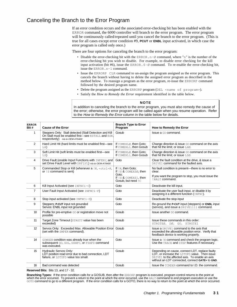
Chapter 1. Programming Fundamentals 3 1
Canceling the Branch to the Error ProgramIf an error condition occurs and the associated error-checking bit has been enabled with theERROR command, the 6000 controller will branch to the error program. The error programwill be continuously called/repeated until you cancel the branch to the error program. (This istrue for all cases except error condition #9, PCUT or ENBL input activated, in which case theerror program is called only once.)
There are four options for canceling the branch to the error program:
• Disable the error-checking bit with the ERROR.n-Ø command, where "n" is the number of theerror-checking bit you wish to disable. For example, to disable error checking for the killinput activation (bit #6), issue the ERROR.6-Ø command. To re-enable the error-checking bit,issue the ERROR.n-1 command.
• Issue the ERRORP CLR command to un-assign the program assigned as the error program. Thiscancels the branch without having to delete the assigned error program as described in themethod below. To reassign a program as the error program, re-issue the ERRORP commandfollowed by the desired program name.
• Delete the program assigned as the ERRORP program (DEL <name of program>).• Satisfy the How to Remedy the Error requirement identified in the table below.
NOTEIn addition to canceling the branch to the error program, you must also remedy the cause ofthe error; otherwise, the error program will be called again when you resume operation. Referto the How to Remedy the Error column in the table below for details.
ERRORBit # Cause of the Error
Branch Type to ErrorProgram How to Remedy the Error
1 Steppers Only: Stall detected (Stall Detection and KillOn Stall must be enabled first—see ESTALL and ESK,respectively) n/a to OEM-AT6400
Gosub Issue a GO command.
2 Hard Limit Hit (hard limits must be enabled first—seeLH)
If COMEXLØ, then Goto;If COMEXL1, then Gosub
Change direction & issue GO command on the axisthat hit the limit; or issue LHØ.
3 Soft Limit Hit (soft limits must be enabled first—seeLS)
If COMEXLØ, then Goto;If COMEXL1, then Gosub
Change direction & issue GO command on the axisthat hit the limit; or issue LSØ.
4 Drive Fault (enable Input Functions with INFEN1; andset Drive Fault Level with DRFLVL) n/a to OEM-AT6400
Goto Clear the fault condition at the drive, & issue aDRIVE1 command for the faulted axis.
5 Commanded Stop or Kill (whenever a !K, <ctrl>K,or !S command is sent)
If !K, then Goto;If !S & COMEXSØ, thenGoto;If !S & COMEXS1, thenGosub, but need !C
No fault condition is present—there is no error toclear.
If you want the program to stop, you must issue the!HALT command.
6 Kill Input Activated (see INFNCi-C) Goto Deactivate the kill input.
7 User Fault Input Activated (see INFNCi-F) Goto Deactivate the user fault input, or disable it byassigning it a different function (INFNC).
8 Stop input activated (see INFNCi-D) Goto Deactivate the stop input
9 Steppers: P-CUT input not groundedServos: ENBL input not grounded
Goto Re-ground the P-CUT input (steppers) or ENBL input(servos), and issue a DRIVE1111 command.
10 Profile for pre-emptive GO or registration move notpossible
Gosub Issue another GO command.
11 Target Zone Timeout (STRGTT value has beenexceeded)
Gosub Issue these commands in this order:STRGTEØ, DØ, GO, STRGTE1
12 Servos Only: Exceeded Max. Allowable Position Error(set with the SMPER command).
Gosub Issue a DRIVE1 command to the axis thatexceeded the allowable position error. Verify thatfeedback device is working properly.
14 GOWHEN condition was already true when thesubsequent GO, GOL, GSHFC, or FSHFD commandwas executed.
Goto Issue a !K command and check the program logic.Use the TRACE and STEP features if necessary.
15 Hydraulic Servos Only:LDT position read error due to bad connection, LDTfailure, or LDTUPD value too small.
Gosub Depending on cause, connect LDT, replace faultyLDT, or increase the LDTUPD value. Then issueDRIVE1 to the affected axis. To enable an axiswithout an LDT connected, connect GATE+ to GND.
16 Bad command was detected Gosub Issue the TCMDER command to I.D. the command.
Reserved Bits: Bits 13, and 17 - 32.
Branching Types: If the error condition calls for a GOSUB, then after the ERRORP program is executed, program control returns to the point atwhich the error occurred. To prevent a return to the point at which the error occurred, use the HALT command to end program execution or use theGOTO command to go to a different program. If the error condition calls for a GOTO, there is no way to return to the point at which the error occurred.
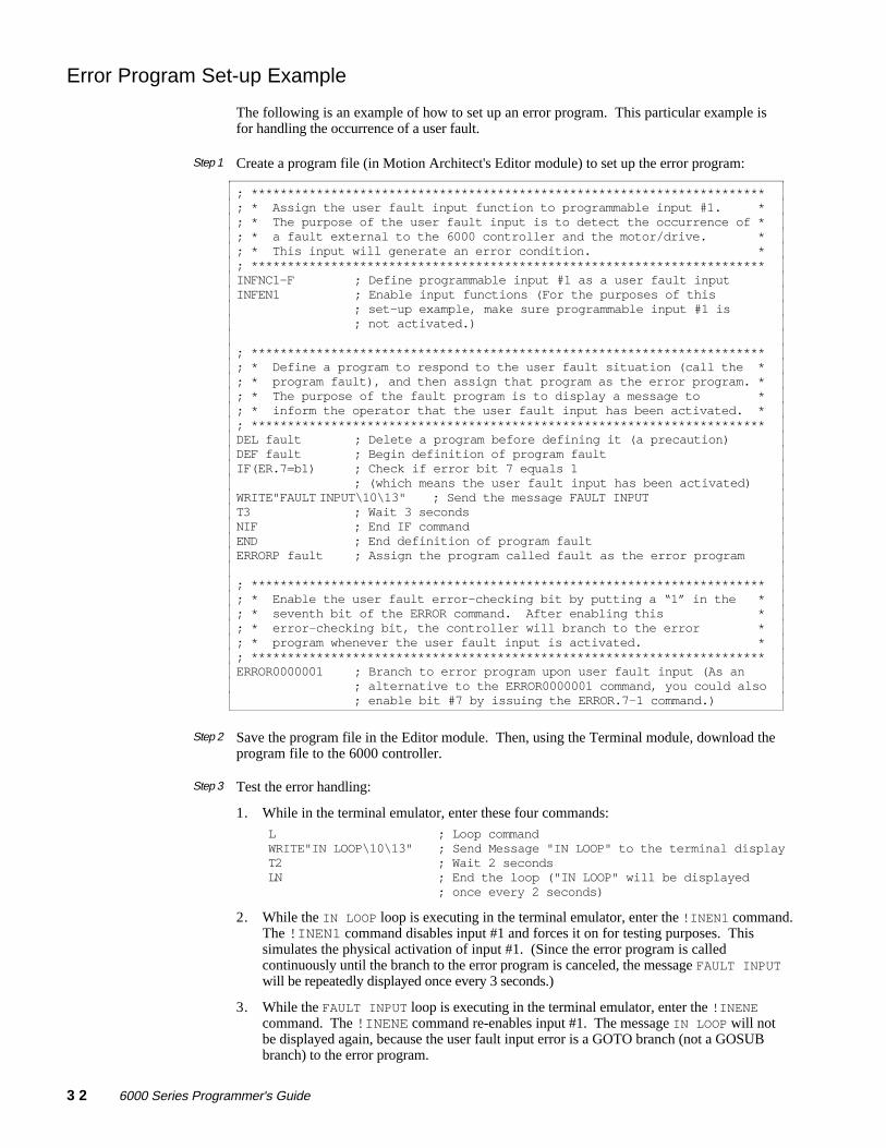
3 2 6000 Series Programmer's Guide
Error Program Set-up Example
The following is an example of how to set up an error program. This particular example isfor handling the occurrence of a user fault.
Step 1 Create a program file (in Motion Architect's Editor module) to set up the error program:
; ***********************************************************************; * Assign the user fault input function to programmable input #1. *; * The purpose of the user fault input is to detect the occurrence of *; * a fault external to the 6000 controller and the motor/drive. *; * This input will generate an error condition. *; ***********************************************************************INFNC1-F ; Define programmable input #1 as a user fault inputINFEN1 ; Enable input functions (For the purposes of this
; set-up example, make sure programmable input #1 is; not activated.)
; ***********************************************************************; * Define a program to respond to the user fault situation (call the *; * program fault), and then assign that program as the error program. *; * The purpose of the fault program is to display a message to *; * inform the operator that the user fault input has been activated. *; ***********************************************************************DEL fault ; Delete a program before defining it (a precaution)DEF fault ; Begin definition of program faultIF(ER.7=b1) ; Check if error bit 7 equals 1
; (which means the user fault input has been activated)WRITE"FAULT INPUT\10\13" ; Send the message FAULT INPUTT3 ; Wait 3 secondsNIF ; End IF commandEND ; End definition of program faultERRORP fault ; Assign the program called fault as the error program
; ***********************************************************************; * Enable the user fault error-checking bit by putting a “1” in the *; * seventh bit of the ERROR command. After enabling this *; * error-checking bit, the controller will branch to the error *; * program whenever the user fault input is activated. *; ***********************************************************************ERROR0000001 ; Branch to error program upon user fault input (As an
; alternative to the ERROR0000001 command, you could also; enable bit #7 by issuing the ERROR.7-1 command.)
Step 2 Save the program file in the Editor module. Then, using the Terminal module, download theprogram file to the 6000 controller.
Step 3 Test the error handling:
1. While in the terminal emulator, enter these four commands:
L ; Loop commandWRITE"IN LOOP\10\13" ; Send Message "IN LOOP" to the terminal displayT2 ; Wait 2 secondsLN ; End the loop ("IN LOOP" will be displayed
; once every 2 seconds)
2. While the IN LOOP loop is executing in the terminal emulator, enter the !INEN1 command.The !INEN1 command disables input #1 and forces it on for testing purposes. Thissimulates the physical activation of input #1. (Since the error program is calledcontinuously until the branch to the error program is canceled, the message FAULT INPUTwill be repeatedly displayed once every 3 seconds.)
3. While the FAULT INPUT loop is executing in the terminal emulator, enter the !INENEcommand. The !INENE command re-enables input #1. The message IN LOOP will notbe displayed again, because the user fault input error is a GOTO branch (not a GOSUBbranch) to the error program.
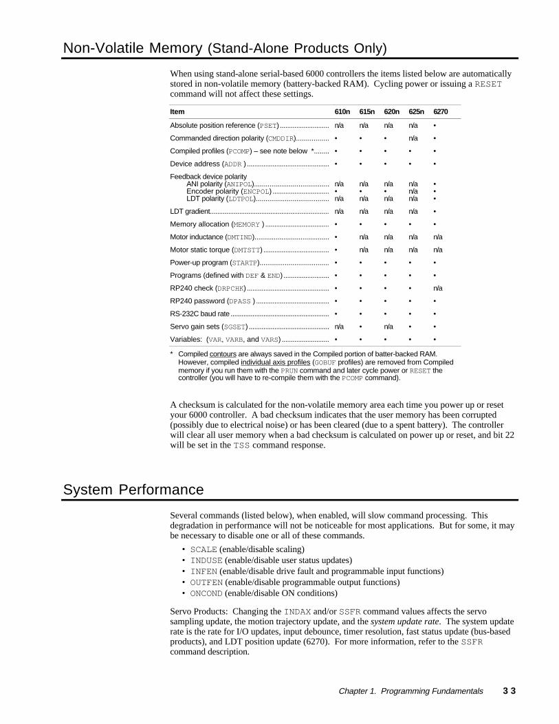
Chapter 1. Programming Fundamentals 3 3
Non-Volatile Memory (Stand-Alone Products Only)
When using stand-alone serial-based 6000 controllers the items listed below are automaticallystored in non-volatile memory (battery-backed RAM). Cycling power or issuing a RESETcommand will not affect these settings.
Item 610n 615n 620n 625n 6270
Absolute position reference (PSET) ...........................
Commanded direction polarity (CMDDIR).................
Compiled profiles (PCOMP) – see note below *........
Device address (ADDR ) .............................................
Feedback device polarityANI polarity (ANIPOL)....................................... Encoder polarity (ENCPOL) ............................... LDT polarity (LDTPOL)......................................
LDT gradient.................................................................
Memory allocation (MEMORY ) ...................................
Motor inductance (DMTIND).......................................
Motor static torque (DMTSTT) ....................................
Power-up program (STARTP)....................................
Programs (defined with DEF & END) .........................
RP240 check (DRPCHK) .............................................
RP240 password (DPASS ) ........................................
RS-232C baud rate ......................................................
Servo gain sets (SGSET) ............................................
Variables: (VAR, VARB, and VARS) ..........................
n/a
•
•
•
n/a•n/a
n/a
•
•
•
•
•
•
•
•
n/a
•
n/a
•
•
•
n/a•n/a
n/a
•
n/a
n/a
•
•
•
•
•
•
•
n/a
•
•
•
n/a•n/a
n/a
•
n/a
n/a
•
•
•
•
•
n/a
•
n/a
n/a
•
•
n/an/an/a
n/a
•
n/a
n/a
•
•
•
•
•
•
•
•
•
•
•
•••
•
•
n/a
n/a
•
•
n/a
•
•
•
•
* Compiled contours are always saved in the Compiled portion of batter-backed RAM.However, compiled individual axis profiles (GOBUF profiles) are removed from Compiledmemory if you run them with the PRUN command and later cycle power or RESET thecontroller (you will have to re-compile them with the PCOMP command).
A checksum is calculated for the non-volatile memory area each time you power up or resetyour 6000 controller. A bad checksum indicates that the user memory has been corrupted(possibly due to electrical noise) or has been cleared (due to a spent battery). The controllerwill clear all user memory when a bad checksum is calculated on power up or reset, and bit 22will be set in the TSS command response.
System Performance
Several commands (listed below), when enabled, will slow command processing. Thisdegradation in performance will not be noticeable for most applications. But for some, it maybe necessary to disable one or all of these commands.
• SCALE (enable/disable scaling)• INDUSE (enable/disable user status updates)• INFEN (enable/disable drive fault and programmable input functions)• OUTFEN (enable/disable programmable output functions)• ONCOND (enable/disable ON conditions)
Servo Products: Changing the INDAX and/or SSFR command values affects the servosampling update, the motion trajectory update, and the system update rate. The system updaterate is the rate for I/O updates, input debounce, timer resolution, fast status update (bus-basedproducts), and LDT position update (6270). For more information, refer to the SSFRcommand description.
