chapter iv hydraulic cement concrete · sec. 412.08 curing precast prestressed concrete ... the...
TRANSCRIPT
June 2016
CHAPTER IV – HYDRAULIC CEMENT CONCRETE ............................................................................ 3
SECTION 401 INTRODUCTION............................................................................................................ 3 SECTION 402 RESPONSIBILITIES ....................................................................................................... 3 SECTION 403 CERTIFICATIONS ......................................................................................................... 4 SECTION 404 FORMS ............................................................................................................................ 4 SECTION 405 FIELD TESTING EQUIPMENT ..................................................................................... 5 SECTION 406 INSPECTION OF PLANT AND EQUIPMENT ............................................................. 6 SECTION 407 MATERIALS USED IN THE PRODUCTION OF HCC ............................................... 9
Sec. 407.01 Cement .............................................................................................................................. 9 Sec. 407.02 Chemical Admixtures ........................................................................................................ 9 Sec. 407.03 Mineral Admixtures ........................................................................................................ 10 Sec. 407.04 Water ............................................................................................................................... 10
SECTION 408 HANDLING AND STORAGE OF MATERIALS ........................................................ 10 Sec. 408.01 Aggregates ....................................................................................................................... 10 Sec. 408.02 Cement and Mineral Admixtures .................................................................................... 10 Sec. 408.03 Chemical Admixtures ...................................................................................................... 11
SECTION 409 HCC MIX DESIGNS ..................................................................................................... 11 Sec. 409.01 HCC Mix Designs using Mineral Admixtures ................................................................ 11 Sec. 409.02 HCC Mix Design Approval Process ............................................................................... 11 Sec. 409.03 Batch Weights / Allowable Field Adjustments ............................................................... 13 Sec. 409.04 Water Content Corrections .............................................................................................. 14
SECTION 410 HCC TESTING .............................................................................................................. 14 Sec. 410.01 HCC Testing Methods ..................................................................................................... 14 Sec. 410.02 Self-Consolidating Concrete (SCC) Testing Methods .................................................... 15 Sec. 410.03 Maturity Meter ................................................................................................................ 15 Sec. 410.04 Concrete Testing ............................................................................................................. 15 Sec. 410.05 Testing Frequencies ......................................................................................................... 17
SECTION 411 HCC PLACEMENT, CONSOLIDATION, FINISHING, FIELD CURING, AND FORM REMOVAL ................................................................................................................................ 21
Sec. 411.01 Placement ........................................................................................................................ 21 Sec. 411.02 Consolidation .................................................................................................................. 21 Sec. 411.03 Finishing .......................................................................................................................... 21 Sec. 411.04 Field Curing..................................................................................................................... 21 Sec. 411.05 Form Removal ................................................................................................................. 21
SECTION 412 PRESTRESSED HCC .................................................................................................... 22 Sec. 412.01 General ............................................................................................................................ 22 Sec. 412.02 Preliminary Plant Approval ............................................................................................. 22 Sec. 412.03 Preliminary Job Requirements ........................................................................................ 23
IV-1
June 2016
Sec. 412.04 Stressing the Bed ............................................................................................................. 24 Sec. 412.05 Tying the Bed and Placing Inserts ................................................................................... 24 Sec. 412.06 Batching Concrete ........................................................................................................... 25 Sec. 412.07 Placing Concrete ............................................................................................................. 26 Sec. 412.08 Curing Precast Prestressed Concrete ............................................................................... 27 Sec. 412.09 Stripping Forms and Releasing Prestress Force .............................................................. 28 Sec. 412.10 Storage Inspection, and Non-Conformance Reports ....................................................... 29 Sec. 412.11 Test Cylinders ................................................................................................................. 29 Sec. 412.12 Testing and Reporting Test Results ................................................................................. 30 Sec. 412.13 Shipment and Reporting .................................................................................................. 31
SECTION 413 PRECAST HCC ............................................................................................................. 31 SECTION 414 PAVEMENT HCC ......................................................................................................... 31 SECTION 415 OVERLAY HCC ........................................................................................................... 32 SECTION 416 SPECIALTY CONCRETES (INCLUDING SELF-CONSOLIDATING, LIGHTWEIGHT, DRILLED SHAFT, MASS, AND ROLLER-COMPACTED HCC) ........................ 32
Sec. 416.01 Self-Consolidating Concrete (SCC) ................................................................................ 32 Sec. 416.02 Lightweight Concrete (LWC) ......................................................................................... 33 Sec. 416.03 Drilled Shaft Concrete (DSC) ......................................................................................... 33 Sec. 416.04 Mass Concrete (MC) ....................................................................................................... 34 Sec. 416.05 Roller-Compacted Concrete (RCC) ................................................................................ 35 Sec. 416.06 Shotcrete .......................................................................................................................... 35
SECTION 417 HYDRAULIC CEMENT MORTAR AND GROUT .................................................... 35 SECTION 418 HCC REPAIR AND COATING MATERIALS ............................................................ 35
Sec. 418.01 Repair Materials .............................................................................................................. 35 Sec. 418.02 Coating Materials ............................................................................................................ 35
APPENDICES ............................................................................................................................................ 37
Appendix A: Self-Certification HCC Plant and Truck Inspection Forms ........................................... A-1 Appendix B: Latex Volumetric Mixer Calibration Procedure and Form ............................................. B-1 Appendix C: Evaporation Rate Chart .................................................................................................. C-1 Appendix D: Definitions of Terms and Abbreviations ........................................................................ D-1 Appendix E: Creating a Concrete Mix Design .................................................................................... E-1 Appendix F: Prestressed HCC Quality Assurance Inspection Items ................................................... F-1
IV-2

June 2016
CHAPTER IV – HYDRAULIC CEMENT CONCRETE
SECTION 401 INTRODUCTION
Chapter IV of this manual defines the Virginia Department of Transportation (VDOT) laboratory and field business practices for Hydraulic Cement Concrete (HCC) operations statewide. Included in this chapter are the references to the current VDOT Road and Bridge Specifications (VRBS), Sections 200, 214, 215, 216, 217, 218, 219, 220, 241, 243, 307, 316, 404, 405, 410, 412, 415, 502, 506, 509, and 519. Achieving high quality HCC requires cooperation and a high level of communication between contractors, consultants, HCC producers and VDOT personnel. This Chapter covers the majority of topics important for VDOT projects; however, no attempt is made to address all potential issues that may arise. On such occasions when this Chapter fails to provide direction, the responsible charge Engineer retains authority over the direction of HCC operations. The Appendix D contains definitions of commonly used terms in VDOT as well as various hydraulic cement concrete operations.
SECTION 402 RESPONSIBILITIES
Central Office Materials Division – The Concrete Program Manager (CPM) has technical oversight of the concrete program and the VDOT Materials Division’s Physical Laboratory. The CPM defines the concrete program, keeps the MOI updated, develops specifications, coordinates research with the Virginia Transportation Research Council (VTRC), serves as a technical resource to the Districts, co-chairs the biannual VRMCA\VDOT Co-Op Meetings and holds a biannual District Concrete Meeting. The Physical Laboratory performs testing and evaluation for the concrete program as well as testing the physical properties of other materials such as bridge bearing pads, epoxy repair materials, concrete repair materials, etc. District Materials Section – approves HCC mix designs and witnesses trial batching; may be responsible for Independent Assurance (IA) testing and/or Verification Sampling and Testing (VST) depending on the contract delivery method; approves Quality Control/Quality Assurance (QC/QA) plans for projects; monitors concrete producing facilities/equipment/personnel certifications. Inspector – responsible for ensuring Contractor is providing HCC that meets contract requirements; may be responsible for QC, IA and/or VST testing. Hydraulic Cement Concrete (HCC) Producer – controls HCC quality and delivery to a project. Contractor – responsible for ensuring the correct class of HCC is placed in a fashion so as to meet specifications and is responsible for quality control (QC) of concrete.
IV-3

June 2016
SECTION 403 CERTIFICATIONS
HCC Field Technician – Reference the Virginia Road and Bridge Specifications (VRBS), Sections 200.06 and 217.07. This certification is required when performing acceptance tests in the field. The VDOT HCC Field Technician certification consists of both the ACI Concrete Field Testing Technician Grade I and the VDOT HCC Field School. HCC Plant Technician – Reference the Virginia Road and Bridge Specifications (VRBS), Sections 200.06 and 217.07. This certification is required to produce HCC at a concrete plant and for driver/technicians of high-performance volumetric truck mixers. Qualified HCC Strength Testing Technician - has current ACI Concrete Strength Testing Technician Certification
SECTION 404 FORMS
Results of tests are recorded on the appropriate form. TL-13 Notice of Shipment of Concrete Cylinders
This form is filled out by the technician molding the cylinders and submitted with each cluster of cylinders to the testing lab to obtain the compressive strength (three 4”x8” or two 6”x12” cylinders) and, if specified, permeability (two 4”x8” cylinders) results.
TL-26 Test Report Laboratory test results for compressive strength (three 4”x8” or two 6”x12” cylinders) and
permeability (two 4”x8” cylinders) are reported on the TL-26. The contents of TL-26 are governed by ASTM C31, C39 and VTM 112.
TL-27 Statement of Hydraulic Cement Concrete Mix Design This form is filled out by the Ready-Mix HCC producer and submitted to the District Materials Section for approval. The TL-27 is checked by the District Concrete Technician and approved by the District Materials Engineer (or by his designee). For precast and prestressed plants, this form is filled out by the producer and submitted to the Quality Assurance or Structures Section for approval. TL-28A Coding Form The plant record (Sections A and B) of this form is completed by the HCC producer’s technician. The HCC producer sends the TL-28A (with Sections A and B completed) to the job site with the first load of HCC. Additional TL-28A’s are sent if additional rows are needed to document the receipt of HCC or a new mix design is sent to the job site. Site record (Section C) is completed by the project inspector.
The HCC producer submits a TL-27 for approval before any HCC is sent to a project. The project inspector submits the TL-13 and the TL-28A along with the appropriate HCC cylinders to the District Materials Section. District Materials personnel may pick up the HCC cylinders and documentation at the job site. These forms can be accessed on the VDOT/Materials Divisions website using the link listed below: http://www.virginiadot.org/business/materials-default.asp
IV-4
June 2016
Information from the TL-13 and the TL-28A is used by the VDOT testing lab to complete a TL-26 test report. A new TL-28A is provided to project personnel with the first load of HCC delivered to the project and if any adjustments are made to the mix on subsequent HCC loads delivered.
SECTION 405 FIELD TESTING EQUIPMENT
Unless otherwise specified by contract documents, the VDOT District Materials Section supplies HCC cylinder molds as well as maintains, supplies and, if specified by the method, calibrates all equipment needed for field testing of freshly mixed HCC. A calibration list is kept current for all equipment requiring calibration (as specified by the corresponding ASTM) by the District Materials Section. Note: The information below applies to Design-Bid-Build projects and may not apply to other alternate delivery projects such as Design-Build, Locally-Administered or Public/Private Transportation Act projects. For alternate delivery projects, it is the responsibility of the AMRL Lab for the project to perform this function for field testing equipment.
(a) Portable Concrete Compression Testing Machines
The Department may place a portable concrete compression testing machine near the job site or centrally locate the machine among several projects for use in testing HCC cylinders (1) for early form removal and construction of superimposed elements in concrete work or (2) for early opening of concrete work to traffic, as outlined respectively in Sections 404.03(j) and 404.03(m) of the VRBS or in Special Provisions. This may be done in remote job areas not easily accessible to a compression testing machine. Portable concrete compression testing machines will be calibrated in accordance with ASTM E4; however, these machines may not meet all requirements of ASTM C39. However, they are deemed sufficiently accurate for on-the-job testing for purposes outlined in the previous paragraph. Whenever erratic results are obtained, the equipment is damaged or there is reason to suspect a malfunction, the District Materials Engineer or designee should be contacted for assistance. At least once every year or if the equipment is moved, the District Materials Engineer should also be contacted for recalibration (or calibration verification) of the machine.
The Contractor, at his option, may furnish a portable compression testing machine. If so, the same instructions outlined in the previous two paragraphs will apply and the machine should be similar to the units furnished by the Department. The machine must have the approval of the Department’s District Materials Engineer or designee before being authorized for use. It is the Contractor’s responsibility to keep his testing machine in good working condition at all times and have the machine calibrated (or calibration verified) at least once every year or each time the equipment is moved. The testing machine must be housed in order to protect it from the weather and sufficient working space must be provided in the enclosure for personnel to conduct the tests.
The portable machines shall meet the following specifications:
(1) The machine shall be capable of accommodating for test a standard 6" x 12" (142.64 mm x 300 mm) or a 4" x 8" (100 mm x 200 mm) concrete test specimen.
(2) It shall have a dial with a minimum diameter of 8 in. (200 mm) and have a minimum capacity of 200,000 lbs. (90 kN). It shall further be graduated to 1,000 lbs. (2 kN) increments.
(3) The pump shall have a dual range operation capacity.
(4) The platens shall be of sufficient area and thickness to accommodate the specimen without deflection.
(5) The machine must be calibrated (or calibration verified) at least once each year to within an accuracy of 1.0 percent of its normal operating range.
IV-5

June 2016
(6) A label should be attached to the machine showing the last date of calibration (or date of verification) and person or firm performing the calibration. The calibration results for each preceding year shall be kept in the records of the Owner.
(b) Air Meters Air meters for the determination of entrained air content in HCC are available from the District Materials Engineer. The air meters are the permanent property of the District. Necessary repairs will be made by the District Materials Section.
(c) Concrete Beam Testing Apparatus In some districts, beam testing machines are distributed by the District Materials Engineer. The beam testing machines must be returned to the District Materials Engineer upon project completion.
Whenever calibration verification of the testing machines is desired during the construction season, they should be delivered to the District Materials Engineer for shipment to the Materials Division. The testing machine will be returned to the District Material Section after the calibration and/or verification has been completed. These machines should be calibrated (or calibration verified) at least once a year.
(d) Concrete Pavement Core Drill A concrete pavement core drill is available upon request from the District Materials Laboratory, for coring base and pavement concrete. Since the equipment and operating crew are limited in number, the operating schedules are most critical, especially when there are several projects requiring coring at the same time in different areas of the District. This applies also to base concrete, since the cores preferably should be obtained prior to application of bituminous concrete mix.
For these reasons, and in order to eliminate costly and time consuming equipment moves, it is necessary that the District Materials Engineer be given written notice one week in advance of any need for the drilling equipment.
The above instructions will require careful planning and attention to construction schedules. The Central Office Materials Division/Physical Lab has portable HCC coring equipment capable of coring vertical surfaces and areas where District coring equipment cannot access. The CPM or his assistant should be contacted when such coring needs arise in order to schedule the coring work.
SECTION 406 INSPECTION OF PLANT AND EQUIPMENT
1) Approval Hydraulic cement concrete (HCC) plants and trucks are approved by one of the two following programs:
(a) National Ready Mixed Concrete Association (NRMCA) Certification Producers electing to use NRMCA Certification for inspection of plant and trucks for VDOT approval are required to complete and sign the form in the Appendix, Section A.
(b) Self-certification
HCC producers electing to perform self-certification for inspection of both plant and trucks are required to complete and sign all of the forms supplied in the Appendix, Section A.
Failure to comply with VDOT requirements for plant and truck certification may result in removal of the plant as an approved HCC supplier, disqualification of trucks for use on VDOT projects and/or decertification of the producer’s VDOT HCC Certified Plant Technician. Documentation must be made available to the District Materials Section that demonstrates compliance with one of the two approval programs. Material source code numbers for plant locations will be obtained through the Materials
IV-6
June 2016
Division/Physical Laboratory. The frequency of self-inspection shall be at a minimum the same as the NRMCA inspection frequency. 2) Documentation Requirements Documentation consists of submitting a Certificate of Compliance to the District Materials Section. This Certificate of Compliance must be signed by the HCC producer’s VDOT HCC Certified Plant Technician. The following documentation shall be retained by the HCC producer and be made available to the District Materials Engineer (DME) upon request:
1. A current List of Approved Trucks for use on VDOT projects. 2. VDOT HCC Plant Technician Certification(s). 3. Approved HCC mix designs shall be kept on file. 4. A current Truck Inspection Report for each approved truck. 5. A current Hydraulic Cement Concrete Plant Inspection Report.
3) Plant/Truck Monitoring Before HCC is provided to a project, the District Concrete Technician may arrange for a visit to the plant. Based upon the Technician’s experience and knowledge of the District’s projects/workload and understanding of potential risks, the Technician may elect to examine any or all of the following:
• The inspection reports for the plant and transit mixing trucks (herein referred to as Trucks). The District Concrete Technician verifies the HCC producer’s inspection reports, both those features that are reported as compliant and those that are problematic with particular attention to the most critical concerns at the plant for producing quality concrete. Regardless of what is found in the reports, the Technician may decide to inspect any or all plant operations and trucks.
• Checking any number of trucks for drum cleanliness and blade wear. If a truck is found to be out of compliance, the District Concrete Technician will draw a line through the truck listed on the HCC producer’s List of Approved Trucks, date and sign the deletion. To reapprove the truck a new Truck Inspection Report must be completed demonstrating compliance to all items on the inspection report. The District Concrete Technician may choose to be present for the re-inspection of non-compliant trucks.
• Plant batching operations. If any areas of non-compliance are noted while inspecting the plant, the District Concrete Technician will fill out a new Virginia Department of Transportation/Materials Division Hydraulic Cement Concrete Plant Inspection Report denoting areas of non-compliance, signing and dating the report at the time of the review. On a follow-up visit, the areas of non-compliance will be inspected to ensure proper action was taken by the producer to correct the problems.
If batch testing is part of the contract requirements, additional portions of the report may be monitored at that time. While the entire inspection of both plant and trucks may be performed, the District Concrete Technician will determine how much verification is needed. In the case where the District Concrete Technician has verified the HCC producer’s inspection report within the last few months, less verification may be justified. A VDOT HCC Plant Certified Technician shall be available during production for VDOT projects. HCC production shall be in accordance with approved HCC Mix Designs. The intent is for some portion of the inspection process to be verified by the District Concrete Technician during each plant visit. 4) Non-compliance Resolution Procedure
IV-7
June 2016
The District Concrete Technician will work with the HCC producer making an effort to resolve non-compliant inspection action items. The accumulation of one or more of the violations below (not all inclusive) may result in the removal of the approved status of an HCC producer.
a) Supplying HCC without using an approved HCC mix design. b) Inadequate maintenance of trucks/equipment (documented in the Truck Inspection Report
and/or the Hydraulic Cement Concrete Plant Inspection Report). c) Not performing the self-inspection or having a valid NRMCA inspection within the prescribed
inspection frequency. d) Failing to comply with specification requirements.
When an HCC producer fails to act within 5 business days on the notification(s) of non-compliance issued by the District Concrete Technician, the DME may begin the process of removing the approval status of an HCC producer. The DME will follow the steps below:
1. The DME will review the District Concrete Technician and HCC producer’s inspection documentation within 5 business days of notification by the District Concrete Technician. If the DME can resolve the matter with the HCC producer, there will be no need to proceed to step 2. If the matter is unresolved, then the DME will proceed to step 2.
2. The DME will issue a written notice of placing the HCC producer on probation. 3. The probation will continue until the inspection action items are resolved and the HCC producer has
demonstrated for at least 3 months of providing HCC to VDOT projects that the inspection action items are not recurring issues.
4. If 5 business days after the date of being notified of being on probation and failing to resolve the inspection action items, the DME may remove the HCC producer, providing written notification of removal. The written notification will outline what actions the HCC producer needs to take to regain an approved HCC producer status.
5. When the HCC producer regains the approved status, the HCC producer will be on a probationary status for a 3 month period demonstrating continued inspection compliance.
Suspensions of HCC Concrete Plant Technician Certifications will be handled in accordance with the VDOT Materials Division Manual of Instructions, Sec. 114.07 Suspension of Certification. Appeal Process: If the decision is to place the HCC producer on probation or remove the approval status of the HCC producer, the HCC producer has 5 business days to appeal the decision in writing to the VDOT Concrete Program Manager. The Concrete Program Manager or designated representative will review the matter and render a decision within 5 business days. If the HCC producer does not agree with the decision of the Concrete Program Manager or appointed representative, then the HCC producer may appeal to the State Materials Engineer or designated representative in writing within 5 business days after the Concrete Program Manager’s decision. The State Materials Engineer’s (or designated representative) decision is final and will be made within 5 business days after receiving the HCC producer’s written appeal. During the appeal process the decision by the DME stands until a ruling is made. Volumetric Mixer Trucks The VRBS, Section 217.09(c) outline the requirements for an automatic mobile continuous mixer, also called a volumetric mixer truck. These units are typically used to produce latex modified HCC. These units must be calibrated prior to HCC placement. The calibration procedure is listed in the Appendix, Section A3. The ingredients tolerances are listed in the VRBS, Section 217.04(b). High Performance Volumetric Mixer Trucks The VRBS, Section 217.05(d) specifies the requirements of the High Performance Volumetric Mixer. These units are capable of producing HCC mixes very similar to a batch plant and a ready-mix truck. The
IV-8
June 2016
ingredients tolerances of a stationary production plant in the VRBS, Section 217.04(a) apply to the high performance volumetric mixer trucks. Since the mixing time in the auger is significantly reduced from that of a ready-mix truck, a tandem auger may be necessary in order to produce a homogenous mixture.
SECTION 407 MATERIALS USED IN THE PRODUCTION OF HCC
This section describes the materials used in the production of HCC, specification references for materials, and the appropriate approved list numbers.
Sec. 407.01 Cement
Cement sources are approved by the Central Office Materials Division’s Physical Laboratory and contained on Approved List No. 85. The cement specification is in the VRBS, Section 214.
Sec. 407.02 Chemical Admixtures
Chemical Admixtures are approved by the Central Office Materials Division’s Physical Laboratory and contained on Approved List No. 1 (Air-entraining Admixtures), Approved List No. 2 (Chemical Admixtures for Concrete Types A, B, C, D, E, F and G), Approved List No. 3 (Chemical Admixtures for Concrete Type S) and Approved List No. 4 (Corrosion Inhibiting Admixtures). The chemical admixture specification is in the VRBS, Section 215. Chemical admixtures are chemicals typically added to HCC during batching operations in order to obtain certain desirable characteristics in the plastic and/or hardened HCC. ASTM C494 lists the following types of chemical admixtures: Type A – water-reducing Type B – retarding Type C – accelerating Type D – water-reducing and retarding Type E – water-reducing and accelerating Type F – water-reducing and high-range water reducing Type G – water-reducing, high-water reducing and retarding Type S – specific performance Chemical admixtures include air-entraining agents, set retarders, accelerators, water-reducing and high range water-reducing agents. Types D, E, F and G are used in HCC to affect more than one property. A generic category, Type S, is referred to as a “specific performance” admixture. A Type S admixture provides a particular performance characteristic not covered by the other chemical admixtures types, like a viscosity-modifying admixture. The purpose of Type S admixture is defined by the manufacturer. The use of chemical admixtures and the procedure for using them must be established to fit job conditions. No standard pattern can be prescribed to fit all jobs, since all jobs and materials differ. For example, use of set retarders in cold weather may be waived by the Engineer. Dispensing of chemical admixtures should always be in accordance with the manufacturer’s recommendation. The accuracy of dispensing chemical admixtures is ± 3 percent as defined by the VRBS, Section 217.04. When chemical admixtures are used, they must be thoroughly mixed into the HCC before the cement begins to hydrate. One of the responsibilities of the HCC producer is to ensure that all of the chemical admixtures used in HCC are compatible. The control of chemical admixture usage is extremely important. A common practice is to use chemical admixtures from the same manufacturer. When the HCC is presented to VDOT
IV-9
June 2016
at the jobsite for acceptance, no additional chemical admixtures are permitted to be added at the jobsite unless authorized by the Department.
Sec. 407.03 Mineral Admixtures
Mineral Admixtures are approved by the Central Office Materials Division’s Physical Laboratory and contained on Approved List No. 24. The mineral admixture specification is in the VRBS, Section 215. Mineral admixtures are added to HCC to mitigate alkali-silica reaction (ASR) and to reduce the permeability of the HCC. When direct percentage replacements by weight are made between portland cement and mineral admixtures, some short term strength loss may be observed. The quantity of mineral admixture used in a VDOT HCC mix is discussed in Section 410. Blends of mineral admixtures may be used if permitted by the Engineer. Ternary blends consist of portland cement and two additional mineral admixtures. Mineral admixtures replace portland cement and rely on the by-products of cementitious hydration for reaction. For this reason, the strength of the HCC at early ages may be retarded when using mineral admixtures. To improve the strength gain in colder weather, additional amounts of cementitious materials may be added, or the concrete mixing and curing temperatures may be increased. Non-chloride accelerators may also be used with caution and approval from the District Materials Engineer (DME).
Sec. 407.04 Water
Water used in HCC must meet the requirements of the VRBS, Section 216. Municipal city/county drinking water is acceptable without further testing.
SECTION 408 HANDLING AND STORAGE OF MATERIALS
Sec. 408.01 Aggregates
Responsibility for aggregates begins with their receipt and stockpiling. Aggregates must be handled in a way to minimize segregation and contamination. If stockpiles are placed on the ground, the location must be 1) cleared of all vegetation and rubbish and 2) leveled and rolled before the stockpiles are started. Material that has been in contact with the ground will be contaminated, and must not be used. Therefore, the loader should maintain at least 12 inches above the ground surface while removing material from stockpiles built on the ground. Adjacent stockpiles of unlike material must not be allowed to come in contact with each other, and shall be separated by bulkheads, if necessary. Aggregates should be maintained at a minimum in a saturated-surface dry condition (SSD). Since an SSD condition is nearly impossible to achieve in the stockpile, aggregates generally contain more water than necessary for an SSD condition.
Sec. 408.02 Cement and Mineral Admixtures
Hydraulic cement and mineral admixtures react with and/or absorb water. Therefore, prior to batching, all cement and mineral admixtures must be stored in a suitable weatherproof structure that will protect them from dampness or water absorption. Cement and mineral admixtures in mobile mixer trucks must be protected from water-absorption prior to batching HCC. When the cement and mineral admixture(s) are proportioned at one point and trucked to the mixer, the cement and mineral admixture(s) must be protected from water while in transit.
IV-10
June 2016
Sec. 408.03 Chemical Admixtures
Chemical admixtures must not be mixed prior to batching unless recommended by the manufacturer. All containers must be thoroughly cleaned before being used to store chemical admixtures. Chemical Admixtures must be stored in areas protected against freezing.
SECTION 409 HCC MIX DESIGNS
In accordance with the VRBS, Section 217.07, ACI 211.1 and 211.2 (“Recommended Practice for Selecting Proportions for Concrete”) are used to develop HCC mix designs (Refer to Appendix E for parts of the Hydraulic Cement Concrete Plant and Field Certification Study Guide for the VDOT HCC mix design process, including the allowable field adjustments and batch weight adjustments). In considering locally available materials, VDOT has developed specifications for designing HCC mixes for durability, economy and longevity. The following information is provided to explain how HCC mixes are designed and approved.
Sec. 409.01 HCC Mix Designs using Mineral Admixtures
VDOT requires Alkali-Silica Reaction (ASR) mitigation. Mineral admixtures are added to HCC to mitigate ASR and to reduce HCC permeability. The quantity of mineral admixture(s) used in a VDOT HCC mix is determined by: 1) following the requirements outlined in the VRBS, Section 217.02, or 2) if required by the contract, testing the HCC in accordance with VTM 112 and using the test result to compare against the specified permeability value (units are coulombs). The greater quantity of mineral admixture as determined by numbers 1 or 2 must be used. The alkali content of each type and manufacturer of cement will be determined from the manufacturer’s annual letter of certification. When calculating the absolute volume of the mineral admixture, the specific gravity must be obtained from the mineral admixture’s mill certificate. This mill certificate must: 1) accompany each load of mineral admixture to a concrete producing facility, 2) be on file at the concrete producer’s facility and 3) be made available to VDOT upon request.
Sec. 409.02 HCC Mix Design Approval Process
In conjunction with MOI Chapter I Section 106.01(c), the District Materials Engineer or designee will review the mix design submitted by the Contractor to determine if it conforms to the specification. Trial batches may be required by the Contract or by the District Materials Engineer for all approved mix designs. The HCC producer shall assume the responsibility for the quality control and condition of all materials during the handling, blending and mixing operations. The producer shall assume responsibility for the initial determination and all necessary subsequent adjustments in proportioning of materials used to produce the specified HCC. The proportion of fine and coarse aggregate shall satisfy proper finishing requirements. Actual batch quantities may be adjusted during the course of the work to reduce changes in workability caused by differences in characteristics of aggregates within specification requirements. Such adjustments are to be made only by the concrete producer and in such a way as not to change the yield. A prescriptive and two performance-based options are specified for preparing documentation for submittal to the Department for HCC mix design approval. For all three, the mix design is approved as documented below: Approval Process
To approve an HCC mix design, the following procedure is used:
IV-11
June 2016
1. The mix design is submitted by the HCC Producer on a TL-27 Statement of Hydraulic Cement Concrete Mix Design form to the District Materials Engineer or designee.
2. If the HCC mix is specific to a contract, the contract is referenced for HCC mix design parameters.
3. Various Approved Lists are referenced to determine if the materials used are from approved sources. Approved cement sources are located on Approved List No. 85. Approved Chemical Admixtures are located on Approved Lists 1, 2, 3 and 4. Approved aggregate sources are found on Approved List No. 5. Approved mineral admixtures are located on Approved List No. 24. The yield is calculated to ensure the material volumes sum to 27.0 cubic feet.
4. The water/cementitious ratio is calculated by dividing the total water in pounds by the sum of the total cementitious materials content in pounds. This value is checked against the maximum water/cementitious ratio specified in the contract (typically found in Table II-17 of the VRBS).
5. The minimum required mineral admixture content is verified by dividing the pounds of mineral admixture by the pounds of total cementitious materials and multiplying by 100. This value must equal or exceed the corresponding minimum value found in Table 1 but may not exceed the maximum mineral admixture content in the VRBS, Section 217.02 unless otherwise approved by the District Materials Engineer or designee.
6. If all of the above criteria are met, then District Materials Engineer or designee signs and dates the HCC mix design denoting approval. A copy is retained on file in the District Materials Section. The original is sent to the HCC producer to be retained in his file and available to VDOT personnel upon request.
7. After determining the weight for each of the components of the mix, the contract may specify or the District Materials Engineer (at his discretion) may request that the Contractor perform a trial batch using the approved mix design. (See the Batch Weights / Allowable Adjustments Section for more detail.) The trial batch must meet all contract document requirements before being used on a VDOT project.
8. Since the specific gravity of aggregate varies widely with type, it must be known for the aggregate being used. Small differences in specific gravity can mean large differences in batch weights.
Refer to the VRBS, Section 217.07 for the following mix design methods: Option 1 - Prescriptive Method The prescriptive method follows the absolute volume design method of ACI 211 for normal, heavy weight and lightweight concrete mix designs using the VRBS, Table II-17 for design criteria. Aggregate properties obtained from the aggregate producer are used for design purposes. This design method is taught in the VDOT HCC Plant & Field Certification Class along with batch weight adjustments and water content corrections and is also included in Appendix E. The VRBS require “one 3-cubic yard production verification batch using the same type of equipment intended for use in supplying concrete to the Department. The proposed mix design will be considered acceptable provided that the plastic properties of the concrete are within the specification limits for the given class of concrete in Table II-17. Strength tests of the verification batch must equal or exceed the design strength, f’c, for the specified class of concrete.” Option 2 – Trial Batch Mix Design Method All requirements in the VRBS, Section 217.07, Table II-17 must be met except the minimum cementitious content is waived. The nominal size of the coarse aggregate must be met for the respective class of concrete
IV-12
June 2016
as well as the maximum water/cement ratio. Furthermore, all coarse and fine aggregate properties must be met except that the grading requirements are waived provided the HCC meets all other contract requirements. To qualify a mix design, the Contractor/HCC producer prepares a minimum of 3 trial batches, each one with differing cementitious materials content over a range anticipated to encompass the design strength, f’c, plus overdesign using the maximum water-cementitious ratio (w/c) encompassing the range permitted for the class of concrete being evaluated. Trial batches may be produced in small scale laboratory batches or truck batches (minimum 3 yd3 volume). In addition to meeting the plastic concrete properties, the HCC temperature (minimum 68 ºF), air content (-1.0 to 1.5 of the target air content) and slump (± 1 inch of the maximum slump) are restricted to minimize variation in the anticipated results. A graph of the cementitious content versus the compressive strength is developed. The required design strength is the 28-day design strength from Table II-17 plus either three times the producer’s standard deviation of their product or if the producer does not have a standard deviation for their product, 1700 psi. The cementitious content can be determined from the graph by referencing the cementitious content from the required design strength. Once the proposed mix is established using the required cementitious content, one 3-yd3 batch is produced using the same type of equipment intended for use in supplying HCC to the Department to verify the mix as designed can meet contract requirements. The proposed mix design is acceptable provided all of the source materials are approved, as well as, the plastic concrete properties, the compressive strength and the permeability (if specified) meet the contract requirements. Option 3 - Documented Field Experience Method All requirements in the VRBS, Section 217.07, Table II-17 must be met except the minimum cementitious content is waived. The nominal size of the coarse aggregate must be met for the respective class of concrete as well as the maximum water/cement ratio. Furthermore, all coarse and fine aggregate properties must be met except that the grading requirements are waived provided the HCC meets all other contract requirements. To qualify a mix design, the Contractor/HCC producer must provide documentation of previous field experience (not necessarily based upon VDOT projects) where:
• the w/c of the proposed mix design is less than or equal to the maximum w/c in Table II-17, • the documented average compressive strength equals or exceeds the design compressive strength
for the respective class of concrete in accordance with f’cr = f’c +3s (where s is the standard deviation of test results),
• the submitted mix contains the same source of materials as the documented data, and all these sources/products are approved and
• the slump and air content are within the specification limits for the class of concrete specified. If the number of tests supplied with the documentation is less than 30, the standard deviation is multiplied by a modification factor as specified in the VRBS, Section 217.07.
Sec. 409.03 Batch Weights / Allowable Field Adjustments
After determining the weight for each of the components of the mix, the contract may specify or the District Materials Engineer (at his discretion) may request that the Contractor perform a trial batch using the approved mix design. If the quantities on the approved mix design do not give the required workability and consistency in the field, the mix can be adjusted by an allowable interchange of coarse aggregate and fine aggregate. The interchange of coarse aggregate and fine aggregate may vary the weight of coarse aggregate and fine aggregate 5 percent, but neither may be changed more than 5 percent. When an interchange of aggregate is needed, the fine aggregate, normally being of less weight than coarse aggregate, is increased or decreased 5 percent and then the coarse aggregate is changed by an equal volume so the design will be 27.0 cubic feet (1 m3).
IV-13
June 2016
The 5 percent adjustment can be used to improve the workability by increasing the amount of fine aggregate, thereby making the HCC with a higher mortar content, or it can be used to increase the slump of the concrete by reducing the fine aggregate quantity (i.e., reducing the surface area of the aggregate) with its large surface area and replacing it with coarse aggregate (having a smaller surface area per given volume). Since the specific gravity of aggregate varies widely with type, it must be known for the aggregate being used. Small differences in specific gravity can mean large differences in batch weights.
Sec. 409.04 Water Content Corrections
The total evaporable water in the aggregate is obtained in accordance with AASHTO T255. The free water (water available for hydration) is the total evaporable water minus the aggregate’s absorbed water. If this number is negative, then the aggregate will absorb water from the mix water. If this number is positive, the aggregate will add water to the total mix water. The free water must be included as part of the total mixing water. The procedure for performing water content corrections is found in the VDOT Hydraulic Cement Concrete Plant & Field Certification Study Guide in Appendix E. The total water for a mix design is comprised of water on the aggregate as well as water added. For very exacting water content corrections, the water in the chemical admixtures are included as part of the mixing water. If the chemical admixture’s water content is insignificant, or if the chemical admixture dosage is insignificant, the water in the chemical admixture may not be used in calculating the total mixing water. If the decision is to include this water, then the percent solids or water of the chemical admixture will need to be known and used in the calculation.
SECTION 410 HCC TESTING
This section outlines the available tests used to evaluate both fresh and hardened HCC.
Sec. 410.01 HCC Testing Methods
Before HCC is placed, there are contract specifications for accepting HCC. First, the HCC is sampled in accordance with ASTM C172 except that the sample is taken after 2 cubic feet of concrete has been discharged. The 2 cubic feet discharged is not used as part of the HCC sample, but, if the HCC is deemed acceptable, may be used in the structure. Typical HCC tests are listed below: Air Content - is tested in accordance with either ASTM C231 or C173. If the concrete is normal or heavy
weight HCC, ASTM C231 or ASTM C173 may be used for testing the air content. However, typically, ASTM C231 (Air Content of Freshly Mixed Concrete by the Pressure Method) is used. If testing Lightweight Concrete (LWC), ASTM C173 (Air Content of Freshly Mixed Concrete by the Volumetric Method; also called the Roll-a-Meter) is used for testing the air content. ASTM C231 (Air Content of Freshly Mixed Concrete by the Pressure Method) shall not be used to test lightweight HCC.
Density (Unit Weight) – is tested in accordance with ASTM C138 (Unit Weight, Yield, and Air Content (Gravimetric) of Concrete) on freshly mixed HCC.
Permeability – is tested in accordance with VTM 112. The permeability test cylinders are prepared and cured the same as the strength cylinders until delivery to the testing laboratory.
Slump (Consistency) – is tested in accordance with ASTM C143 (Slump of Hydraulic Cement Concrete). The slump indicates the workability of the HCC mixture.
Strength – is tested in accordance with ASTM C39 (Test Method for Compressive Strength of Cylindrical Concrete Specimens). Samples are prepared and field-cured in accordance with ASTM C31 (Making and Curing Concrete Test Specimens in the Field).
IV-14

June 2016
Temperature – is tested in accordance with ASTM C1064 (Temperature of Freshly Mixed Concrete).
Sec. 410.02 Self-Consolidating Concrete (SCC) Testing Methods
Slump Flow – tested in accordance with ASTM C1611. The slump flow is generally 20 to 26 inches with the Visual Stability index of “0” or “1” being acceptable. This test determines the ability for SCC to flow without segregating.
J-ring test – tested in accordance with ASTM C1621. The maximum allowable difference between the slump flow and the J-ring test shall be no greater than 2 inches. This test demonstrates the ability of the SCC to flow and consolidate around reinforcing steel.
Making strength and permeability cylinders – molded in accordance with ASTM C1758. Segregation Test – tested in accordance with ASTM C1610. This test is not always included as part of the
contract acceptance tests, but may be specified as a test performed during trial batching. This test method covers the determination of static segregation of SCC by measuring by weight the coarse aggregate content (washed over a No. 4 sieve) in the top and bottom portions of a column mold and comparing the results. The difference in aggregate weights between the top and bottom portions should be minimal.
Sec. 410.03 Maturity Meter
ASTM C1074 is a procedure for estimating HCC strength by means of the maturity method. The maturity index is expressed either in terms of the temperature-time factor or in terms of the equivalent age at a specified temperature. This practice requires establishing the strength-maturity relationship of the HCC mixture in the laboratory and recording the temperature history of the HCC for which strength is to be estimated. This test procedure may be used to estimate nondestructively the in-place strength for any HCC structure such as pavement or mass HCC. Section 316.04 of the VRBS cites this method as an option for opening HCC pavement to traffic. Additionally, this method may be used to estimate the HCC strength of drilled shafts in determining when the work on the drilled shaft or an adjacent drilled shaft may occur. Furthermore, this method may be used to estimate the time for removal of form work. The maturity method is not used as an HCC strength acceptance test. To approve the use of the maturity meter, the Contractor must submit test data in accordance with ASTM C1074 to the District Materials Engineer or designee before use on a project.
Sec. 410.04 Concrete Testing
The Contractor/HCC producer is required to produce HCC in accordance with specification limits for delivery to the job site. The VDOT HCC Field Technician will then perform the following tests: Sec. 410.04.01 Plastic (or Fresh) Concrete Testing
Sampling/testing frequencies are located in Section 410.05 of this manual. When the truck load of HCC is presented to VDOT for testing, the air content, slump, concrete temperature and unit weight (if specified) are tested.
If the air content of the concrete has been determined to be low by the use of the pressure meter, additional air entraining admixture may be added one time to the concrete in those loads that are on site or in transit. The producer’s certified technician will determine the addition rate as well as supervise the addition. The quantity should be measured in a clear, graduated, measuring device, and added to a minimum of one to two gallons (4 to 8 liters) of water prior to addition to the mixture, provided the water-cement ratio is not exceeded. The mixer drum should be reversed to allow the additional air entraining admixture to be dispensed directly on top of the concrete mixture. An additional 70 revolutions of the mixer should be made
IV-15

June 2016
at full mixing speed to thoroughly disperse the admixture throughout the concrete. The concrete is then to be retested for conformance to the specifications. If the increased dosage does not provide air contents within the specified range, the concrete shall be rejected.
For the concrete to be batched, after the initial field adjustment, the air content must be adjusted at the plant and verified before shipment.
Strength and permeability (if specified) cylinders are cast and stored in accordance with ASTM C31 from the same sample. Sec. 410.04.02 Hardened Concrete Strength is tested in accordance with ASTM C39. Permeability testing is performed in accordance with VTM 112. The air content of hardened HCC may be analyzed by the Department. The procedure should be used with discretion under the direction of the District Materials Engineer.
Sec. 410.04.02.01 Failing Strength Tests If failing strength tests are encountered, an effort should be made to establish whether proper sampling and testing procedures were followed. Given proper sampling and testing protocol are followed, the VRBS, Section 217.08(b) is followed in handling low strength concrete. If the Contractor is required to develop an investigative plan to demonstrate that the in-place HCC meets the structural requirement of the design, then the following should be considered in approving the plan:
• Is there a need to determine the in-place strength if the Design Engineer provides documentation that the HCC test results are adequate for the HCC to remain in-place?
• How will the in-place strength be determined? VDOT does not recognize the Schmidt Rebound Hammer, the Windsor Probe or the Impulse Velocity tests for acceptance. The Schmidt Rebound Hammer and the Impulse Velocity tests do not damage the HCC. The Windsor Probe produces slight damage to the concrete surface that will need to be repaired if used. Any three or a combination of the three can be used to determine the area(s) to be sampled if cores are needed. The Schmidt Rebound Hammer is sensitive to variations in shallow HCC depths and the presence of steel. The Windsor Probe results can vary considerably if coarse aggregate is encountered when shooting the probe into the HCC surface.
• If cores are taken in accordance with ASTM C42, what damage will be done that affects the structural integrity or the aesthetics of the structure? How will the damage due to coring be repaired and what repair material will be used?
• What remedial action is needed to achieve the design life? Will the HCC need to be treated with a sealer such as a silane or siloxane? Will a more durable sealer need to be used such as an EP-3 or EP-5 epoxy?
Sec. 410.04.02.02 Failing Permeability Tests VTM 112 uses a rapid curing method to prepare samples for testing permeability for non-latex HCC. As such, there is no correlation between cores taken in the field for permeability and the standard 28-day permeability testing. Unless the contract specifies otherwise, coring for permeability will not be permitted. The District Materials Engineer reserves the right to core for permeability if he has compelling reason to do so. If he decides to obtain cores to test for permeability, both the in-place permeability and the rapid-cure method permeability values should be tested. These values may be used to demonstrate whether a short-term (silane or siloxane) or a long-term (EP-3 or EP-5) sealer will be applied. There should be no reason to core latex HCC for permeability testing unless there is reason to believe that the latex was not added. If latex HCC is cored, the permeability test should be performed without further curing.
IV-16

June 2016
Sec. 410.05 Testing Frequencies
HCC testing frequencies are defined in Tables IV-1, IV-2 and IV-3 for Design-Bid-Build projects,
Increasing or Decreasing Testing frequencies:
• Testing frequencies may be increased at the discretion of the responsible charge Engineer if questions arise regarding HCC quality.
• When consistency is observed in testing fresh HCC properties (air content, density, slump and temperature), the responsible charge Engineer may reduce testing frequencies. However, when testing demonstrates out-of-compliance HCC, testing frequencies return to at least the minimum(s) specified in Tables IV-1, IV-2 and IV-3.
• Reducing the testing frequency of hardened concrete properties should be approached judiciously since this increases the risk of accepting non-conforming HCC. However, one example where reduction in frequency should be considered is that of making strength cylinders for signal and light pole foundations. The District Materials Engineer should evaluate the frequency of making strength cylinders for signal and light pole foundations based upon the placement schedule.
IV-17
June 2016
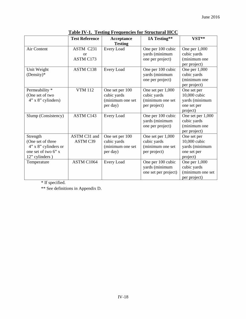
Table IV-1. Testing Frequencies for Structural HCC
Test Reference Acceptance Testing
IA Testing** VST**
Air Content ASTM C231 or
ASTM C173
Every Load One per 100 cubic yards (minimum one per project)
One per 1,000 cubic yards (minimum one per project)
Unit Weight (Density)*
ASTM C138 Every Load One per 100 cubic yards (minimum one per project)
One per 1,000 cubic yards (minimum one per project)
Permeability * (One set of two 4” x 8” cylinders)
VTM 112 One set per 100 cubic yards (minimum one set per day)
One set per 1,000 cubic yards (minimum one set per project)
One set per 10,000 cubic yards (minimum one set per project)
Slump (Consistency) ASTM C143 Every Load One per 100 cubic yards (minimum one per project)
One set per 1,000 cubic yards (minimum one per project)
Strength (One set of three 4” x 8” cylinders or one set of two 6” x 12” cylinders )
ASTM C31 and ASTM C39
One set per 100 cubic yards (minimum one set per day)
One set per 1,000 cubic yards (minimum one set per project)
One set per 10,000 cubic yards (minimum one set per project)
Temperature ASTM C1064 Every Load One per 100 cubic yards (minimum one set per project)
One per 1,000 cubic yards (minimum one set per project)
* If specified. ** See definitions in Appendix D.
IV-18

June 2016
Table IV-2. Testing Frequencies for Miscellaneous HCC
Test Reference Acceptance Testing
IA Testing** VST**
Air Content ASTM C231 or
ASTM C173
One per day (minimum one per project)
One per week (minimum one per project)
One per month (minimum one per project)
Unit Weight (Density)*
ASTM C138 One per day (minimum one per project)
One per week (minimum one per project)
One per month (minimum one per project)
Permeability* (One set of two 4” x 8” cylinders)
VTM 112 One per 250 cubic yards (minimum one set per project)
One per 2,500 cubic yards (minimum one set per project)
One per 25,000 cubic yards (minimum one set per project)
Slump (Consistency) ASTM C143 Two per day (minimum one per project)
One per week (minimum one per project)
One per month (minimum one per project)
Strength (One set of three 4” x 8” cylinders or one set of two 6” x 12” cylinders )
ASTM C31 and
ASTM C39
One per 250 cubic yards (minimum one set per project)
One per 2,500 cubic yards (minimum one set per project)
One per 25,000 cubic yards (minimum one set per project)
Temperature ASTM C1064 One per day (minimum one per project)
One per week (minimum one per project)
One per month (minimum one per project)
* If specified. ** See definitions in Appendix D.
IV-19

June 2016
Table IV-3. Testing Frequencies for Pavement HCC
Test Reference Acceptance Testing
IA Testing** VST**
Air Content ASTM C231 or
ASTM C173
One per hour One per day (minimum one per project)
One per week (minimum one per project)
Unit Weight (Density)*
ASTM C138 One per hour One per day (minimum one per project)
One per week (minimum one per project)
Permeability* (One set of two 4” x 8” cylinders)
VTM 112 One per day of production, or every 0.1 mile of paving, whichever is greater (minimum one set per project)
One per 10 days of production (minimum one set per project)
One per 100 days of production (minimum one set per project)
Slump (Consistency) ASTM C143 One per hour One per day (minimum one per project)
One per week (minimum one per project)
Strength (One set of three 4” x 8” cylinders or one set of two 6” x 12” cylinders )
ASTM C31 and ASTM C39
One per day of production, or every 0.1 mile of paving, whichever is greater (minimum one set per project)
One per 10 days of production (minimum one set per project)
One per 100 days of production (minimum one set per project)
Temperature ASTM C1064 One per hour One per day (minimum one per project)
One per week (minimum one per project)
Pavement Thickness VTM 26 One per 0.1 mile (minimum one per project)
One per mile (minimum one per project)
One per project
Flexural Strength (used for opening to traffic and not an acceptance test)
ASTM C78 As deemed necessary to determine opening to traffic
None None
* If specified. ** See definitions in Appendix D.
IV-20
June 2016
SECTION 411 HCC PLACEMENT, CONSOLIDATION, FINISHING, FIELD CURING, AND FORM REMOVAL
Reference the appropriate VRBS Sections 217, 316, 404, 412, 502, 504, 506 and 509 for specifications in relation to the proper placement, consolidation, finishing and field curing of HCC.
Sec. 411.01 Placement
Before HCC placement, determine if the proper temperature requirements are met. No HCC should be placed on frozen surfaces. In general the surfaces coming into contact with the HCC should be 40 °F and rising. In addition, HCC placement limitations for HCC temperature and heating/cooling HCC ingredients are located in the VRBS, Section 217.10. Conveying devices and forms should be clean and surface-damp prior to placement of HCC. If placing HCC over existing HCC, the surface of the existing HCC (free of laitance, dirt and loosely adhering particles) should be in a moist condition such that no water is contributed to or removed from the HCC being placed.
Sec. 411.02 Consolidation
HCC consolidation requires using various means such as form vibration (not usually viable in the field), use of insertion vibrators as well as rodding, spading and floating, in accordance with VRBS, Section 404.03(c). Air voids decrease HCC strength. Aside from entrained air, HCC should be placed in a way that minimizes air voids, especially near form surfaces where exposure to freezing and thawing is most severe.
Sec. 411.03 Finishing
The HCC finish will be specified in the contract documents. Overworked HCC results in an improper air void system in the first quarter inch of the HCC surface. Such a condition results in spalling and surface delamination. The surface should be finished to the proper specification producing a closed surface without affecting the air void system. If a form finish is required, no further finishing work should be performed. If an inordinate amount of voids are seen on the HCC surface, the District Materials Section should be contacted for assistance.
Sec. 411.04 Field Curing
The first few hours are especially critical in curing HCC. Moisture lost during initial curing may significantly reduce HCC strength and durability as well result in plastic shrinkage cracking. Also, with thin-bonded overlays, loss of moisture is even more critical where the quantity of available water is low and the potential for moisture loss is high. Water may be lost due to evaporation or to absorption by the underlying HCC. Appendix A-4 contains an evaporation rate chart used to determine when precautionary measures should be taken to minimize the potential for plastic shrinkage cracking. The VRBS, Section 404.03(l)1. specifies the maximum permissible evaporation rates.
Sec. 411.05 Form Removal
References: VRBS Section 404.03 specifies the required HCC strength before forms can be removed. Typically, a set of three field-cured cylinders are used to determine if the HCC has sufficient strength to remove the forms.
IV-21
June 2016
SECTION 412 PRESTRESSED HCC
This section covers the prestressed HCC inspection and acceptance process.
Sec. 412.01 General
Prestressed HCC is utilized in girders, box beams, voided slabs, piles, deck panels and other products for bridges and buildings. These components are manufactured in a plant with special equipment to accommodate the handling of prestressing strands. The VRBS, Section 405.03 require the plant to be certified by the PCI, which imposes a number of requirements for quality on the plant. The part most pertinent to our work is the requirement of the plant to have an independent (not part of the production manager’s chain of command) QC Department staffed with qualified personnel. The role of the VDOT QA inspector is to perform QA monitoring of production and QC. Essentially the duties are to ensure the QC Department is performing its duties in accordance with the Department’s Specifications and contract documents (plans and special provisions), PCI policies for Quality Control (PCI MNL 116) and the plant’s QC policies. The QA inspector will serve as the communication link between the plant and the Department, predominantly through the Central Office Structures Section. The QA inspector shall be certified by PCI as a QCPC Level II or Level III inspector, a Professional Engineer licensed in the Commonwealth of Virginia, or working under a responsible charge PE as a QA inspector.
The nature of prestressed concrete construction requires absolute control of uniformity in all operations by the Producer, in order that each piece is as nearly as practical to the properties of the other pieces in all respects for any group used in a single bridge or structure. Another reason for the careful control of production is the fact that unlike reinforced concrete members, prestressed concrete components experience nearly all of their design stress during manufacture and throughout their effective life, while reinforced concrete only experiences stress near its design limit a few times over its effective life. In addition, the act of applying prestress to girders, box beams and voided slabs (or any other component without a symmetric pattern of strands) causes deformation (called camber or hog) by design which is further subject to creep over time. The results of camber and creep can cause the component to become unacceptable and therefore must be monitored and controlled by the producer.
QA monitoring shall be a continuous process beginning before the first batch of concrete is mixed or the first strand is stressed, through stressing and tying the beds, batching, testing and placing concrete in the forms, curing, releasing the prestress, stripping, storing, monitoring and ultimately loading the components for shipment to the job site.
The steps given below are a general guide through the process of producing prestressed concrete. Several specifications and other policies have a bearing on the QC process including the VRBS, Sections 217, 223, 226, 233, 407, 406, 404 & 405, the PCI manual for Quality Control MNL 116 and manual of standard repairs for prestressed concrete MNL 137, various ASTMs concerning sampling & testing fresh concrete, making cylinders, testing hardened concrete and finally the plant’s own Quality Control Manual. In addition to the articles below, the QA inspector should be aware of the plant’s QC policies; however, these do not supersede VDOT specs and the contract.
Sec. 412.02 Preliminary Plant Approval
The first step in the QA process is verifying the plant is certified by PCI to manufacture prestressed concrete structural components. The plant is required to furnish upon request a copy of their current PCI
IV-22
June 2016
certification. The plant is also required to provide a copy of their most recent PCI inspection results for the purpose of determining if the plant is making a good faith attempt to rectify the discrepancies identified in the most recent PCI audit.
Sec. 412.03 Preliminary Job Requirements
Upon notification of award from the customer, the Central Office Structures Section shall be notified of the intent to manufacture prestressed concrete components for a VDOT project with the associated project number, at least 21 days in advance of the date to begin batching concrete for production (VRBS Section 405.03). This information shall be used to assign inspection often obtained through the use of third party inspection companies. The notice shall include the VDOT project number, the number and type of components to be furnished to the project, the required strength, permeability, unit weight and other parameters for the concrete used in each component, the beginning and ending date for casting each type of product and the anticipated shipping schedule for the products. (VRBS Section 108.01) The producer shall prepare and submit for review shop drawings denoting all dimension, materials and steps necessary to describe the forming and stressing to plant personnel. These drawings shall be submitted to the engineer for review (VRBS, Section 105.10) and a copy shall be provided to the QA inspector showing the engineer has completed his review. Prior to production the producer shall submit his concrete mix design to VDOT Materials Structures Section using VDOT form TL-27. The mix proportions and sources of all constituent materials shall be clearly denoted on the form. All sources of constituent materials shall be approved in advance by the VDOT Materials Division. Trial batch results or historical data shall also be provided to support the choice of the mix indicating it is able to meet the project specifications 28-day compressive strength, permeability, unit weight and any other contract requirement. The producer shall allow sufficient time to complete testing, review, and approval of the mix design from VDOT Materials Structures Section prior to production. The QA inspector should verify the cement, aggregates, admixtures and other ingredients of the concrete are from approved sources and stored in accordance with the specifications and with due concern for maintaining the integrity of the materials. (MOI, Section 409) The QA inspector should verify QC personnel are qualified to:
• oversee prestressing operations, • test fresh concrete properties, • mold cylinders and • test hardened concrete in the laboratory for compressive strength.
The QA inspector working with the producer’s QC Department should make a preliminary inspection of the bed and forms to ensure there are no concerns prior to production. Forms shall be made of steel, have the proper dimensions for the product being produced and be in good serviceable condition. (Section 412 and VRBS Section 405.05(a)). In accordance with PCI MNL 116, prior to stressing the bed, the producer is required to compute the strand elongation that will occur during tensioning operations. The calculations shall include allowance for seating of the chucks, abutment rotation or other physical conditions that exist based upon the producer’s experience at his facility. The calculations shall be based on the actual modulus of elasticity obtained from the steel certification for the specified strand lot and verified by the QA Inspector. These calculations shall be prepared by a PCI Level II or Level III inspector, and made available to the QA inspector. The QA inspector will verify that every lot of strand is sampled in accordance with the VDOT MOI, Section 204.32(d)). The QA inspector will periodically:
IV-23
June 2016
• inspect the mild reinforcement and other inserts to ensure they meet the contract requirements and shop drawing details
• verify that the producer has the certifications for these parts on file in his project specific file.
Sec. 412.04 Stressing the Bed
The QA inspector should witness the stressing of the steel strands. The QC Inspector is required to measure and record data for the prestressing operation. PCI specifications require all strands to be stressed to initial (10% of the final load) before stressing any strands to the final load. Occasionally some strands will be stressed to a lower level to accommodate the producer’s procedure and these should be noted on the shop drawings. The QA inspector should make sure the producer stresses the strands to the appropriate level as noted on the shop drawings (or other controlling contract documents) during the prestressing operation. PCI MNL 116 requires the first strand to be checked for force and elongation before stressing additional strands. Every tenth strand is required to be checked (10% of the strands) as stressing is underway. It is good practice to check the first strand whenever the jack is placed on a new layer in the strand pattern to make sure the jack is aligned properly at the bulkhead. Upon completion of the prestressing operation, all strands shall be checked for elongation. The elongation data, the date, the time, the temperature and the bed number shall be recorded on the appropriate form(s) and kept in the project records. Upon completion of stressing, the full length of the bed shall be visually inspected to ensure the strands are properly stressed, without kinks and without an excessive number of wires broken during the stressing operation. Typically the Department prescribes 7-wire strands. Any seven wire strand with more than one wire broken shall be removed following proper destressing procedures and replaced with a new strand. Also if more than 2% of the wires in a product are broken, enough strand(s) shall be removed and replaced to reduce the percentage to less than 2%. Cautionary note: While this manual is unable to address all safety concerns that may arise at a prestress concrete plant, and particularly during prestressing operations, the QA inspector is to be aware that stressing strands is inherently dangerous. The plant will have safety requirements for all personnel. The QA inspector is expected to observe these safety requirements. Typically, flashing lights and horns are used to alert workers to active prestressing operations. Avoid unsafe zones around the beds during these operations and wait for acknowledgement before moving into these areas to inspect any part of the work. It is advisable to travel with a member of the plant staff at this time.
Sec. 412.05 Tying the Bed and Placing Inserts
Upon completion of stressing the strands, the producer will place and tie mild steel reinforcement as noted on the shop drawings, in accordance with the contract documents and the steel strand manufacturer’s recommendations. If there is a conflict between any document requirements, the QC Department shall submit a Request for Information (RFI), to the Materials Division’s Structure’s Section for resolution. Mild steel reinforcement is placed in the bed and tied to itself and the strand. However, the weight of all mild reinforcing shall be supported by chairs or other means to prevent deflection of the strands from their proper profile. Generally, transverse vertical reinforcing steel bars shall be spaced close together at the ends of prestressed members and further apart near the middle region. Doing so assists in increased resistance to shear stresses in the final component. If the concrete prestressed member has protruding bars, these bars are typically required to be of corrosion resistant steel tied with corrosion resistant ties. Piles are usually reinforced with a continuous steel spiral that varies in pitch being spaced wider in the middle and closer at the ends. Some products require internal void forms. Voided slabs have circular cylindrical forms that run along the longitudinal axis of the slabs. The Department’s Structure and Bridge Division recommends that these be
IV-24
June 2016
made of Styrofoam and not hollow cardboard forms. Box beams, about 24 to 30 inches in depth, are also constructed with Styrofoam void forms. However, the specifications require the contractor to cast the bottom slab before placing the Styrofoam and upper reinforcing steel cage in the form. Form voids shall not be tied to the prestressing strand (VRBS Section 405.05(a)). Otherwise, the strand may shift during concrete placement causing the void form to float. Likewise, the form must be secured against shifting laterally to maintain the proper reinforcing steel clear cover and the engineer-designed centroid of the piece. At the completion of tying the mild steel reinforcement and securing the voids, the producer will close the bed. This is when the side forms are set and secured to the pallet to prevent shifting during casting. The inside forms are sprayed with a release agent to prevent the concrete from bonding to the form work. No release agent is to be sprayed or applied to the prestressing strands. Form release agent on the prestressing strands prevents or reduces bonding of the concrete to the strand. Also, at this time the QA inspector should perform a pre-pour inspection with a member of QC staff. The side and top clearance of steel reinforcement (clear cover) from the forms should meet the design standards (usually 1 ½” clear cover over the bars). It is permissible to tie mild steel reinforcement at every other bar intersection, except in areas where the spacing is wide. The steel should be reasonably free from surface rust form release agent. Minimal concrete laitance or other deleterious material is permitted in the bottom of the form. The producer’s QC inspector(s) guide(s) the production workers in the proper location of inserts and other items. If the QA inspector discovers any perceived errors in steel placement or any out of tolerance dimensions, he will notify the QC inspector of the problem. The QC inspector initiates the corrective action. If the problem is not resolved, the QA inspector should document the perceived problems on the applicable drawing (with photographs as needed) and then discuss the problem with top management of the QC Department. If this fails to resolve the issue, then the QA inspector should contact the VDOT Materials Division, Structures Section. All problems should be resolved with the producer at the earliest opportunity. However, the QA inspector should never direct the efforts of plant workers or act in a manner as to control the production of the work.
Sec. 412.06 Batching Concrete
The aggregate moisture content should be checked gravimetrically twice daily. Most producers have moisture meters to monitor the aggregate moisture content during HCC batching. Anytime the aggregate moisture content is suspect, a gravimetric analysis should be performed by the producer. Aggregate water content corrections are addressed in Sec. 410.04. Typically, prestressed HCC mixes are well below the maximum water/cementitious ratio. The QA inspector should become familiar with the method the plant uses to control and confirm batch weights. The QC Inspector should ensure that all HCC tolerances in the VDOT Specifications and maintain permanent records of the batch weights. Qualification of batch plant equipment and operators is under the purview of the QC Inspector. Having batched the concrete, typically three or more yards at a time, the concrete will be conveyed to the bed where fresh concrete testing is performed by ACI qualified plant technicians. The QA Inspector should observe the testing of the concrete and make notes including the current weather and ambient temperature. In addition to testing the fresh concrete for temperature, unit weight, air content and consistency (either a slump or a flow used for SCC), the producer shall make cylinders for strength testing. Three cylinders are required for each strength test when using 4x8 cylinders and two are required for strength testing when using 6x12 cylinders. If permeability cylinders are required, then two additional 4x8 cylinders shall be made. The producer will want to strip the forms and release the prestress force at an early age; however, by contract, stripping and cutting the strands shall not occur before the concrete has reached a strength (f’ci noted in the
IV-25
June 2016
plans). Producers typically wish to attain this strength by the next morning (usually about 12 hours after casting is complete). The producer is also required to show that the product has attained the contract specified 28-day strength. Often the producer checks the progress of the strength gain at 7-days, sometimes a little more or less time. Therefore a producer would have to make at least nine cylinders from a batch to document the strength of the product. Occasionally a product does not reach strength within the timeframe the producer is striving toward and the producer wishes to conduct an additional test. Therefore, to help the producer avoid using all the cylinders the producer is encouraged to make three extra cylinders. For these reasons The QA Inspector should request the producer make twelve cylinders per cluster, although they are required only to have enough to demonstrate they met the contract requirements. Producers should be discouraged from thinking they will just drill cores to sample a product if they don’t get the strength they want when breaking cylinders. The producer shall make subsequent batches of concrete and bring a copy of the batch ticket with each load to the QA Inspector. The last batch of concrete used in that bed is also required to be tested for fresh concrete properties and cylinders must be made for that batch as well. Often these cylinders are more important because a few hours may pass while the concrete is placed in the bed. The second cluster of cylinders will be less mature when tested for stripping strength. The QA Inspector is also empowered to ask for fresh concrete testing on any batch he has reason to believe is not within specification. He should note a reason for requesting the test in his daily notebook, such as after a light rain, or because the mix appeared to have too much air content, or a breakdown or delay in the batching operation. Likewise if a batch appears to be out of tolerance he should ask for both fresh concrete testing and the making of strength samples.
Sec. 412.07 Placing Concrete
After batching and testing, if the concrete meets the fresh properties, it shall be placed in the forms. Placing concrete should be observed when the QA Inspector’s duties do not require him to be somewhere else. The concrete should be placed in the forms, not dropped any great distance. Should very tall formwork be needed, the producer shall either provide ports in the formwork or use a tremie hose to prevent the concrete from dropping more than 5 feet (Ref. VRBS, Section 404.03(c)). Many products are cast using SCC. SCC is more prone to segregation and should be watched carefully. Structural lightweight concrete (LWC) with a unit weight less than 100 pcf, or “specified density concrete” (SDC), with a unit weight below 125 pcf are being used more frequently too. If the fresh unit weight meets the specified contract weight then the weight is considered acceptable. If it does not, trial batch results may be used to determine what the fresh unit weight may be for acceptance. If no trial batch results are available or otherwise the data is inconclusive, the strength cylinders may be weighed and measured to determine their unit weight. However, hardened concrete density is often different than the fresh concrete density and should be reviewed judiciously. HCC (not SCC) shall be deposited and vibrated in the forms. Form vibrators may also be used but should not be turned on for an extended period of time. Handheld vibrators should be inserted into the concrete to a depth of three to six inches into previously deposited layers. They should be withdrawn before a watery sheen is seen building up around the vibrator at the surface. Excessive use of vibration will cause the coarse aggregate to settle to the bottom of the formwork. If the vibrator is pressed against reinforcement it will cause aggregates to move off the steel and paste will be the only component of the mix able to bond with the reinforcement. On the other hand, vibration is essential to consolidating the concrete around reinforcement and releasing trapped water and air on the underside of formwork such as the top surface of the bottom bulb in Bulb-T beams. As the placing team moves along the formwork, workers will follow along to finish the top surface and place metal clips along the flange tips (used to form the bridge deck later over girders). Over finishing the HCC
IV-26

June 2016
results in a weak paste on the surface. This is a problem because to attain composite action, the precast piece must bond with the cast-in-place deck or topping slab later. The stresses acting at the top of the piece are shear stresses on the top surface, so a weak concrete surface on the prestressed piece reduces the structures ability to maintain the bond. In addition to overworking the surface, the inspector should be mindful of large amounts of bleed water from other causes as well as poor curing conditions that allow the surface paste to lose water too rapidly as may result from high winds. The final steps before covering the bed include raking the top surface of beam products to create a rough surface for the deck concrete to form a bond with the prestressed concrete beams, and the insertion of galvanized steel clips to facilitate placing the corrugated steel deck forms later.
Sec. 412.08 Curing Precast Prestressed Concrete
Once the piece is cast and finished, it should be quickly covered to prevent moisture loss. Blankets are used along with waterproof tarps, polyethylene film, curing compound, wet burlap or other approved curing methods. If high-temperature curing is to be employed by the producer, a procedure should be followed to prevent conditions that would cause too little or too much water on the top surface of the pieces. If moist-curing is incorporated after casting, the piece(s) should be cured to prevent water loss prior to the concrete obtaining release strength. The temperature under these conditions should be maintained between 50 and 90 °F. If heat is applied to decrease curing time, accelerated curing guidelines should be followed. Accelerated curing includes several different methods of applying heat to a concrete product after casting to decrease the curing time of the concrete prior to stripping and release of the prestress force. Accelerated curing is defined by PCI as the application of heat to increase concrete curing temperature above 104 °F. Some of the methods include radiant heat, solar heat and steam curing. The first two do not contribute water to the curing conditions so additional precautions must be taken to prevent moisture loss. Excessive moisture loss can lead to problems such as crazing, plastic shrinkage cracking, discoloration, efflorescence, etc. When using any source of heat for curing, the producer should have documented initial set strength results obtained through penetration resistance testing in accordance with ASTM C403. The concrete should obtain initial set, defined as 500 psi by this test, before steps are taken to begin accelerated curing. The producer can introduce heat prior to reaching release strength, but the concrete temperature rise must be limited to 10 ° F per hour with a maximum temperature of 104 °F or 40 degrees greater than the concrete temperature at the time of placement, whichever is less. Temperature monitoring devices should be placed with the concrete member being subjected to accelerated curing at a minimum of 2 evenly spaced locations. The temperature measuring device should monitor and record concrete and enclosure temperatures throughout the curing period and the data obtained plotted on a time vs. temperature graph for review and record keeping purposes. The application of heat should be controlled and maintained evenly throughout the curing enclosure and should not exceed a rise of 80 °F per hour nor 180 °F maximum. The concrete temperature increase during accelerated curing should not exceed a rise of 36 °F per hour. If it is suspected that there are areas that are receiving greater levels of heat compared to the rest of the enclosure, one of the temperature measuring devices should be placed in that area to maintain the concrete temperature within specification. When steam is utilized as an accelerated curing method, the curing enclosure should be maintained at a minimum 95 percent humidity during the cure period. Steam jets utilized within the enclosure should not be positioned to apply steam or heat directly to the forms or concrete. Products such as Bulb-T beams with flanges both top and bottom are vulnerable to cracks caused by the steel forms expanding inducing pressure against the underside of the top flange and putting tensile strains on the web during curing. Steam should be free-flowing throughout the curing enclosure and any point measured within the enclosure should not differ
IV-27
June 2016
by more than 20 °F. Concrete products subject to steam or other accelerated curing methods should continue the curing condition until the release strength of the concrete has been achieved. If during the curing procedure, heat is terminated prior to the concrete member obtaining release strength, heat shall not be reintroduced to the member. With the reintroduction of heat, the concrete is being subjected to the thermal differentials that may cause cracking or other detrimental effects to the concrete member. Once release strength is met, forms should be removed and detensioning of the strand should take place while the concrete member is still hot. The specifications do not permit placing concrete in forms when either the forms or anything inside the forms is 40 degrees F or below (Ref. Section 404, VDOT Specifications).
Sec. 412.09 Stripping Forms and Releasing Prestress Force
Generally, after twelve or more hours, the producer will test three cylinders to demonstrate he has attained the required strength for releasing the prestress force, stripping the forms and moving the piece(s) to storage. When breaking cylinders, the QC Department should perform this in accordance with ASTM C39 with an ACI certified lab technician (Ref. also 410.01 MOI). If a tested cylinder is notably below the specified release strength the producer need not break additional cylinders until the product has a longer period to gain strength. Once a tested cylinder achieves the desired strength, two additional cylinders must be tested to demonstrate the concrete has the required strength. Thus, an average of three cylinders shall be used in accordance with ASTM C39 (Ref. also table IV-1, section 410.05 MOI). Having demonstrated the concrete has attained the release strength in both initially-cast and final cylinders on the bed, the producer shall then strip the forms to prevent stresses at form joints from developing as the prestress force is released. With the forms stripped off, the QC and QA inspectors may make an inspection of the pieces while the workers are burning the strands at each end. This is referred to as the post-pour inspection. The inspectors should look for cracks, cold joints, honeycombing, depressions, discolored areas indicating a problem, consolidation around inserts or any inserts that may have shifted. If anything is noted it should be brought to the attention of the QC department. The producer will cut the strands, usually by burning with a torch, in a predetermined pattern that will minimize the effect of eccentricity on the member (Ref. Section 405.05(b) VDOT Specs.). Strands should be cut in such a manner that restraint on the pieces is minimized allowing the piece to deform as prestress is applied to the piece, usually by cutting the same strand at each end first at the fixed bulkhead and then immediately at the opposite end. If the piece has an eccentric strand pattern, it will deflect upwards due to the physical effects of the prestress. The amount of deflection, called camber, should be measured from a straight line at midspan and recorded as “Release Camber”. This should be checked against the plans and must be within 50% of the predicted value. Once the strands are all cut, the piece will be moved from the bed to storage. The piece should be marked with a unique piece number before it is lifted from the bed. The piece may only be handled at the specific lifting points cast into the piece for that purpose. For multiple lifting points, spreader beams are often employed. In this case, the piece should be rigged so that every lifting point takes up the weight of the piece at the same time, because this is the assumption used by the designer to check the number of required lifting points. Once moved to storage it must be supported at the bearing points noted on the plans. If pieces are stored in stacks, they may not be stacked in a manner that causes dead load to be superimposed on pieces lower in the stack. Dunnage shall be rigid, and the beam or piece should be at least six inches above the ground.
IV-28
June 2016
Sec. 412.10 Storage Inspection, and Non-Conformance Reports
In addition to the post-pour inspection, regular visits should be made to inspect pieces in the storage yard. The QA Inspector should note any problems including cracks that may develop due to shrinkage or tension as the piece matures and the camber continues to grow due to creep. Particular attention should be paid to beam and girder ends. The sudden development of prestress force in this location and the presence of circular holes or other inserts cast into the girder, particularly the thinner web region, makes the girder very vulnerable to cracks perpendicular to the direction of the strands. This is due to a combination of stresses and strains. If at any time a question arises concerning the process or the condition of a particular piece, the QC and QA inspectors are expected to discuss the situation with one another. In many situations measurements may be obtained that may be used to determine if the product is out of tolerance. For example, if problems have been occurring with the batching equipment for a job being produced elsewhere at the plant, the QA inspector may request fresh concrete testing and compression samples for the VDOT product to ensure the problems with the batching equipment have been addressed with regard to the requirements for the VDOT products. If, after reviewing the data, the QA and QC inspectors agree there is no deviation from the specifications, the QA inspector need only note that in his daily log and move forward. If after considering the situation and measurements available, consulting the specifications, PCI Code and the plant’s Quality Assurance Manual, either inspector believes there is reason to believe the product does not meet the contract requirements, the QC department shall prepare a non-conformance report (NCR) on the piece(s) involved. Measurements adequate to quantify and locate the problem shall be obtained along with the piece number(s) affected. Often a sketch of the piece will be needed to describe the problem. All this information along with the full VDOT project number shall be sent to the Structures Section in Central Office Materials. In addition to information to quantify the problem, the producer should propose a resolution to address the problem. The Structures Section has found that it is often most expedient to quantify repairs matching the condition to one of the standard repairs found in PCI MNL-137, Manual for the Evaluation and Repair of Precast, Prestressed Concrete Bridge Components. Except for bug hole repairs, which are covered in the VRBS, all other repair proposals should be prepared with due regard for the PCI standard. If, however, the condition does not match one of the standard conditions, the plant should develop and propose their method for repair. When an NCR is received, it will be reviewed for the nature of the problem to determine if others should be consulted about the situation, and reviewed to make sure all the necessary information is in the submittal. Additional information may be requested from the producer at any time. The Structures Section will discuss and consult with other engineers and respond to the QC Department. For quickest turnaround, the plant and QA inspector should always communicate about the status of all NCRs.
Sec. 412.11 Test Cylinders
Test Cylinders are essential to demonstrating the product has met the strength requirements. Standard practice in the prestressed industry is to cure cylinders with the product so they represent as nearly as possible the strength of the product. Also, unlike most other concrete products and because so many special measures are available to the producer for accelerated curing, the cylinders must be placed with the product under the protective blankets and exposed to the same moisture, steam or other conditions affecting the curing rate. However, many DOTs have departed from this historical practice and have specific requirements for curing cylinders and the producer must be reminded of our requirements.
IV-29

June 2016
Cylinders are made for testing hardened concrete. Producers usually test cylinders at early ages to accelerate the use of their forms. In recognition of this it is an industry standard for the engineer to determine an acceptable strength for the forms to be stripped and the strands to be cut imparting their stress onto the concrete member. The required strength will be noted on the contract drawings, should also be noted in the shop drawings and is generally 80% of the specified 28-day strength. The note on the contract drawings is the most reliable place to find the requirements for the contract. Producers often try to demonstrate that the product has reached the 28-day strength well in advance of the 28 days, and typically break a second set of cylinders at 7 or 14 days for this reason. Regardless of the outcome of this early age testing, the Department requires the producer to have a set of cylinders tested at 28 days. This is due to the current process of monitoring quality based on statistical results in addition to specific results for a single cast product. In order to maintain the integrity of the statistical data, testing at a specific age is needed so the data belongs to the same statistical population. In addition to strength testing, all concrete specified as A5 is required to be low permeability. Permeability testing requires two additional cylinders and the test is performed on cylinders cured for 28 days. The producer must either have the test apparatus and qualified personnel, or they must send the samples to a qualified third party testing lab to have the test performed. An exception to this rule occurs when the producer chooses to add corrosion inhibiting admixtures to the mix during production. When this is the case, the producer must have this noted on his approved mix design submittal or identified in advance as during the pre-production meeting with the Department. The QA Inspector should check batch tickets to ensure the admixtures are being used when this is the case. Strength test results, particularly at early age testing, often fall below the target because the concrete has not been given enough time to cure and gain strength and the producer is eager to move forward to the next step of production. For this reason, the producer may have to repeat compression testing hours or days later. In order to avoid running out of cylinders the producer often casts three or more additional cylinders as a minimum to be prepared for this situation. Finally, PCI has a standard for testing cylinders that only require two for early age testing, one from each end of the bed, and the PCI standard for testing at 28 days was to use three 4x8 cylinders from each end of the bed and averaging the strength to determine the test result. However the ACI and ASTM committees have developed a standard for testing concrete cylinders that VDOT has adopted. In this method, three samples must be tested and the values averaged to obtain a single test result. In order to comply with this approach, three cylinders must be tested to demonstrate compression strength for release, not just one. This is required for each end of the bed where products are cast. Taking all this into consideration, three cylinders for testing at release, three cylinders for testing at an early age such as 7 days, three cylinders for performing 28 day testing, three cylinders in reserve, and two cylinders for testing permeability, all for each cluster required at each end of the bed, producers will need to make fourteen cylinders in each cluster to have enough to include three in reserve. This situation should be discussed with QC before casting products has begun so they may make sure their technicians understand how many cylinders are needed. Further, the QC department must prepare a place adequate to store the cylinders and mark them so they are easily identified for the product they represent.
Sec. 412.12 Testing and Reporting Test Results
The producer‘s qualified HCC strength testing technician tests the HCC cylinders. If possible, the QA Inspector should witness strength testing and record values in his notes for the purpose of monitoring the HCC quality. Often producers will schedule testing for release strength early in the morning so production crew may proceed with cutting the strands, stripping the forms and turning over the bed for a new day of production.
IV-30
June 2016
If one or two cylinder test results fall notably below the required strength in an early age test (either release or sometime before 28 days), the producer is not required to test all three cylinders and may abandon that test. However, the results should still be recorded in the event subsequent issues arise where consideration of the strength gain becomes important. The test at 28 days should be completed with all three cylinders, regardless of the results. It is important that the Department have a record of the 28 day strength test results for the purpose of monitoring the quality of the concrete and to provide a reference for any discussions concerning non-conforming pieces. If the 28-day strength test does not meet the required strength specified in the contract, the products represented by that test are rejected. If the producer wishes the Department to consider other factors in making their determination, they may submit a non-conformance report to the Department. If the Department decides the piece may be accepted they will notify the contractor, the plant and the VDOT QA inspector.
Sec. 412.13 Shipment and Reporting
The QA inspector coordinates with the QC Inspector for final inspection before shipment.
Upon completion of the final inspection, the QA inspector stamps the piece on the marked end near the QC department’s stamp. The QA inspector receives a copy of the Bill of Lading (BOL) and stamps the three copies (QA, plant and truckers copies). The QA inspector prepares a shipping report for the pieces shipped that day noting the piece mark, nominal size & length and 28-day cylinder strength. A copy of the shipping report is sent to the VDOT Central Office Materials Division Structures Section within ten days of the shipment. The CO materials Division’s Structures Section will review the report to ensure it has all the required information (dates, project number, contractor name, etc.) and then send two copies to the District Materials Section. One copy is for the project inspector and the other copy is placed in their project files with a copy of the stamped BOL.
SECTION 413 PRECAST HCC
VRBS reference: Section 302, MOI 204.22 (c) and MOI 204.26 (d)
Precast producers shall submit mix designs to the VDOT Materials Quality Assurance Section using the Concrete Mix Design TL-27 Form. At times precast HCC producers submit HCC mix designs with the nominal maximum size coarse aggregate less than the specified HCC class in order to achieve better consolidation. This is acceptable provided all other aspects of contract specifications governing the acceptance of HCC are met.
SECTION 414 PAVEMENT HCC
VRBS reference: Section 316
HCC pavement may be opened to traffic if
1. the modulus of rupture strength tested in accordance with ASTM C78 (third point loading) has reached a minimum of 600 psi or
2. the pavement is at least 14 days old.
The Maturity Test Method (ASTM C1074) may be used to determine the opening to traffic strength. However, the acceptance test for pavement HCC is the compressive strength in accordance with ASTM C39 for the specified class of HCC. In addition, air content, consistency, and other tests are performed.
IV-31
June 2016
HCC pavement will also be checked for depth in accordance with VTM 26, by drilling cores from the completed pavement. Drilling cores for depth check will be performed by the District Materials Section.
SECTION 415 OVERLAY HCC
HCC for bridge deck or pavement overlays may use one or more mineral admixtures (silica fume, latex, Class F fly ash, ground-granulated blast furnace slag or a combination of these) in the mix. Generally, No. 67, No. 78 or No. 8 grading coarse aggregate is used and determined by the depth of the overlay in conjunction with the presence of reinforcing steel.
SECTION 416 SPECIALTY CONCRETES (INCLUDING SELF-CONSOLIDATING, LIGHTWEIGHT, DRILLED SHAFT, MASS, AND ROLLER-COMPACTED HCC)
Depending upon project conditions, some HCC mixes must meet additional requirements for special applications. Special provisions may be inserted into contracts that place additional specifications on the HCC supplied to a project. Special provisions must be reviewed carefully to ensure all requirements are met. Generally, a contractor may obtain a bid price on a particular class of HCC from the producer. Unless the contractor informs the producer that the HCC must meet additional contract requirements, the HCC producer will submit a bid based upon the price of a generically approved mix design. However, the special provision may dictate the following:
• additional ingredients such as more or less cementitious materials and/or admixtures • placement procedures such as pumping or use of high-density pavers • have supplemental testing requirements such as the use of the maturity meter or temperature-
matched curing for the HCC before the mix design is approved and during construction. For this reason the producer should be informed of the contract requirements for the HCC specified as far in advance as possible. Specialty HCCs may include SCC, lightweight, drilled shaft, mass and roller-compacted HCC. These specialty concretes are considered separately below.
Sec. 416.01 Self-Consolidating Concrete (SCC)
SCC is often made by using a higher cementitious content, decreasing the coarse aggregate content, increasing the fine aggregate content, using viscosity modifying admixtures and additional high-range water reducers. Water/cementitious material ratios for SCC mixes are generally less than 0.4. The chemical admixture manufacturer/supplier’s technical representative is a good source for mix design information. SCC mixes do not follow the ACI 211 mix design process, but rely more on plant/field experience. SCC is more susceptible to segregation than most typical VDOT HCC mixes. Instead of performing the slump test (ASTM C143), the slump flow (ASTM C1611) and the J-ring (ASTM C1621) tests are performed. The slump flow test evaluates the ability of the SCC to flow and rates the SCC on its tendency to segregate based upon a visual stability index. Typical contract acceptance values for the visual stability index test are “0” or “1”. The J-ring test evaluates the ability of the SCC to flow around steel. A typical value of the slump flow test is 20 to 29 inches depending on the application. The value for the J-ring test is generally no more than 2 inches less than the slump flow test value. If segregation is seen in the HCC mix, generally the water content of the sand is inconsistent or there is not enough fine material. Cylinders for strength and permeability are cast in accordance with ASTM C1758.
IV-32

June 2016
The best application for SCC is where: • there is heavy congestion of steel, • there is little room for internal vibration and • the resulting HCC surface is relatively flat and smooth.
Sec. 416.02 Lightweight Concrete (LWC)
VDOT uses LWC in prestressed bridge beams and concrete decks. When a structure is designed with LWC, the elements are of less density than normal weight HCC. There are three types of LWC. 1) All lightweight HCC consists of both lightweight coarse and fine aggregates. 2) Sand lightweight HCC consists of normal weight fine (sand) and lightweight coarse aggregates. This is the LWC that VDOT typically specifies. 3) Specified density lightweight HCC which is a blend of normal weight and lightweight aggregates designed to achieve a specified density. The preferred method of accepting LWC based upon density is by performing ASTM C138 on the fresh HCC. Typical values of fresh HCC density for normal weight HCC is approximately 145 pcf, whereas all or sand LWC is less than 120 pcf. ACI 211 defines the mix design process for lightweight HCC. Common problems with LWC include:
• Inconsistency in the mix due to variation in the water content of the aggregate; which draws attention to the importance of proper pre-wetting of the LW aggregates.
• Over-vibrating during placement resulting in segregation
Sec. 416.03 Drilled Shaft Concrete (DSC)
The drilled shaft HCC (DSC) special provision requires SCC. The special provision also requires the Contractor to supply details of the drilled shaft placement, including proposed operational procedures for free fall, tremie or pumping methods. The proposed Concrete Placement Plan shall ensure that sufficient concrete is at the job site or in transit to the job site so that the entire placement can be accomplished without delay and:
1. Include location of the HCC plant, number of trucks, estimated delivery times, estimated time between trucks, and number of trucks at the site before placement begins.
2. Indicate the use of tremie or HCC pump, de-airing lines, details of the seal to be used at the bottom end of the tremie or HCC pump line.
3. Breakdowns of HCC plants, trucks, or traffic problems shall be considered under this Concrete Placement Plan.
4. Include an estimate of the HCC placement and over-placement time per drilled shaft.
If required in the plans, a trial shaft is constructed. Testing of DSC is as described under “SCC or Self-Consolidating Concrete”. Tremie or pumped DSC for drilled shafts has an additional requirement for the slump test (ASTM C143) to ensure that the first load placed is still as workable as the last load placed since the first load rises to the top as HCC is continuously placed. Typically, a DSC trial batch is required. If the DSC will be tremied or pumped, the Contractor shall demonstrate that the DSC mix can maintain at least a 4-inch slump throughout the anticipated time of DSC placement. As the DSC is tremied and moves to the surface of the drilled shaft, the DSC must remain in a plastic state, otherwise the HCC will freeze, lock or plug the shaft to the point where no additional DSC can be pumped into the shaft. On some projects a steel sleeve is placed into the drilled shaft. If a 4-inch slump is not maintained throughout the entire DSC
IV-33
June 2016
placement, the steel sleeve can bond to the HCC. When this occurs and the steel sleeve is specified to be removed after the DSC placement, it may not be possible to remove the steel sleeve. Furthermore, DSC has a low permeability specification where the trial batch permeability value must be 500 coulombs below the specification maximum. Free fall is discouraged and is allowed only if approved by the Engineer since during the fall, especially when the HCC hits the reinforcement cage, segregation is possible.
Sec. 416.04 Mass Concrete (MC)
MC is defined by the American Concrete Institute (ACI) 116R as: any volume of concrete with dimensions large enough to require that measures be taken to cope with the generation of heat from hydration of the cement and attendant volume change to minimize cracking. Given this definition, the question, “What is MC” will still arise. Some references may designate MC as any HCC with a minimum dimension of 3 feet; others may stipulate 5 feet. The uncertainty is due to many factors that will affect the generation of heat such as • the geometry of the element, • the ingredients, especially the amount of portland cement, • the initial HCC temperature, and • the environment However, VDOT will identify on the contract plans what structure or what part of a structure is MC or specify a minimum dimension in the special provision. When referring to that part of a structure identified as MC, the MC must meet the contract requirements found in the “Mass Concrete Special Provision.” The special provision requires that temperature sensors be placed into the structure at designated locations. The temperature during the MC curing process must not exceed a specified temperature maximum for any given sensor. Also, the maximum temperature differential between any two sensors is defined. To meet these requirements, the MC mix design allows for more of the portland cement be replaced with a mineral admixture than is normally permitted. Class F Fly ash contents in excess of 30% and slag contents in excess of 50% are common. Additionally, some HCC producers will take into consideration the structural design and use computer programs to optimize their MC mix design. ACI 211 provides guidance to develop MC mix designs. Often design engineers will specify the addition of cooling tubes to the structure. The cooling tubes (if specified) remove trapped heat from within the HCC element by circulating water through the cooling tubes during the MC curing process. The critical MC curing period is generally the first 5 days where excess heat is generated, potentially resulting in thermal cracking. Note that excess steel may be added to the structure to prevent or control these cracks. Some studies indicate that the cooling tubes produce inconsistency in the curing process – that is, hot and cold spots resulting in differential strength gain within the HCC element. Frequently, VDOT does not permit the use of cooling tubes in recognition of this potential condition as well as the cost associated with the materials/installation of the cooling tubes. A well-designed MC mix can minimize the need for cooling tubes. The reasons for the two temperature criteria are: 1) the maximum temperature is set to avoid delayed formation of ettringite within the hardened cementitious matrix that can result in cracking, and 2) the maximum temperature differential is established to minimize thermal cracking where the inside of the structure, due to heat generation, expands more than the outside of the structure, and thus produces a crack during the period of cement hydration. Cracks occur when the tensile forces in the HCC exceed the tensile strength of the HCC.
IV-34
June 2016
Sec. 416.05 Roller-Compacted Concrete (RCC)
RCC is used by VDOT in paving low-volume HCC roads or high volume roads with an overlay to provide a smoother riding surface. RCC mixes have very low water/cementitious material ratios, usually less than 0.35. ACI 207 provides guidance in designing RCC mixes in addition to methods of handling and placement. Often, test sections will be specified in order to optimize RCC mix designs and placement methods. Typically, the same equipment used to place asphalt concrete is used to place RCC with the exception that a high-density paver and a vibratory steel roller are recommended to achieve adequate compaction. The percent compaction varies, but generally is about the same as when compacting asphalt or at least above 90% compaction after the paver. A good goal for adequate compaction is 98% or greater after the final finish typically with the roller.
Sec. 416.06 Shotcrete
References: VRBS Sections 412.02(a), 412.03 (f) Prepare cores in accordance with ASTM C1604.
SECTION 417 HYDRAULIC CEMENT MORTAR AND GROUT
Reference the MOI, Chapter II, Section 204.11(a) for the acceptance of high strength mortar and grout. Reference the VRBS, Section 218.03 for hydraulic cement mortar and grout. On some projects grouts are specified. The grout is tested in accordance with ASTM C939 to determine the time of efflux of a specified volume of fluid hydraulic cement grout through a standardized flow cone. Once the water content for the determined flow is set, this becomes the maximum amount of mixing water permitted.
SECTION 418 HCC REPAIR AND COATING MATERIALS
Sec. 418.01 Repair Materials
HCC repair materials shall be tested in accordance with VTM 132. Manufacturers submit independent laboratory data on each HCC repair material to the Central Office, Materials Division’s Physical Laboratory for evaluation. Products meeting the requirements on Approved List No. 31 will be added to the list.
Sec. 418.02 Coating Materials
HCC Sealants, Stains, and Coatings meet the requirement of and are contained on Approved List No. 30. Requirements for products included on this list are the following :
Three A4 General HCC beams (3” x 4” x 16”) are prepared in accordance with the Virginia Department of Transportation’s Road and Bridge Specifications, Sections 217.07 except that no mineral admixture is used. The beams are moist-cured for 14 days and air-cured the remaining 14 days. One beam is the control and left uncoated. The two remaining beams are coated in accordance with the manufacturer’s recommendations.
These three beams are tested in accordance with the following: ASTM C666, 300 cycles, Method A modified with 2% sodium chloride Weight Loss * maximum 7% Durability Factor 60% minimum Surface Rating maximum 3
IV-35

June 2016
If the material is a coating and not a stain or sealant, a minimum of 90% of the coating must remain intact. The measurement of 90% is approximated by visual measurement.
*The average weight loss of the two coated beams should be no greater than 7% of the control beam.
IV-36
June 2016
APPENDICES
A -- Self-Certification HCC Plant and Truck Inspection Forms B -- Latex Volumetric Mixer Calibration Procedure and Form C – Evaporation Rate Chart D – Definition of Terms and Abbreviations E – Creating a Concrete Mix Design F – Prestressed HCC Quality Assurance Inspection Items
IV-37

June 2016
Appendix A: Self-Certification HCC Plant and Truck Inspection Forms
Virginia Department of Transportation/Materials Division
Hydraulic Cement Concrete Plant Certificate of Compliance
Hydraulic Cement Concrete (HCC) Producer Name - ___________________________________ HCC Producer Location - _____________________________________________ _____________________________________________ _____________________________________________ This signed document certifies:
1. that the plant location above has either (please circle one):
a. a current/valid NRMCA Certification for plant and/or trucks b. or completed VDOT Inspection Reports for plant and/or trucks
2. that all plant equipment and trucks used on VDOT projects meets or exceeds the requirements listed
on the Truck Inspection Report and the Hydraulic Cement Concrete Plant Inspection Report.
3. a List of Approved Trucks is on file for this plant location.
If a truck is sent from another producer’s plant (either an approved source or not an approved source for HCC), the List of Approved Trucks must be updated for this plant location. Proof of current truck inspection must be on file at the plant location where the truck is being dispatched. This documentation will be made available to VDOT upon request. Signed by - ________________________________________ (print name) ________________________________________ (signature)
A-1
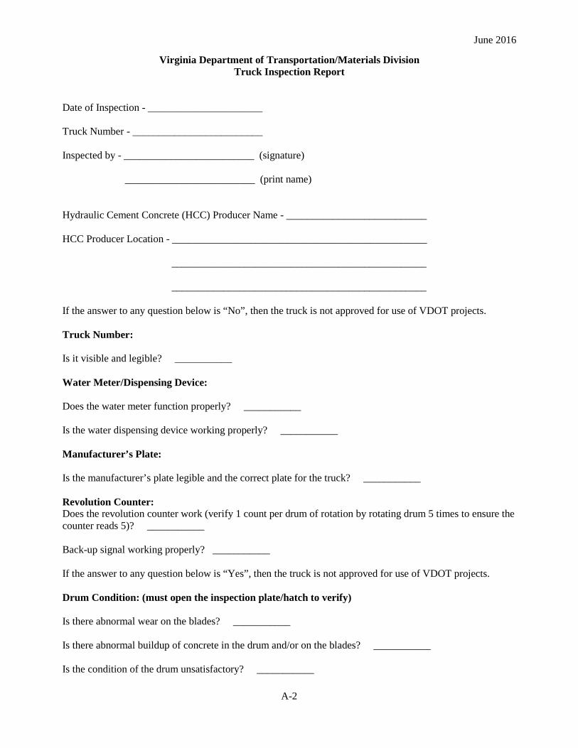
June 2016
Virginia Department of Transportation/Materials Division Truck Inspection Report
Date of Inspection - ______________________ Truck Number - _________________________ Inspected by - _________________________ (signature) _________________________ (print name) Hydraulic Cement Concrete (HCC) Producer Name - ___________________________ HCC Producer Location - _________________________________________________ _________________________________________________ _________________________________________________ If the answer to any question below is “No”, then the truck is not approved for use of VDOT projects. Truck Number: Is it visible and legible? ___________ Water Meter/Dispensing Device: Does the water meter function properly? ___________ Is the water dispensing device working properly? ___________ Manufacturer’s Plate: Is the manufacturer’s plate legible and the correct plate for the truck? ___________ Revolution Counter: Does the revolution counter work (verify 1 count per drum of rotation by rotating drum 5 times to ensure the counter reads 5)? ___________ Back-up signal working properly? ___________ If the answer to any question below is “Yes”, then the truck is not approved for use of VDOT projects. Drum Condition: (must open the inspection plate/hatch to verify) Is there abnormal wear on the blades? ___________ Is there abnormal buildup of concrete in the drum and/or on the blades? ___________ Is the condition of the drum unsatisfactory? ___________
A-2

June 2016
Does the drum fail to rotate both clockwise and counterclockwise with variable speed? ___________ Are the chutes aluminum? ____________ Do the chutes contain an unsatisfactory amount of hardened concrete? ___________ Note: This document addresses the production of quality HCC and does not absolve the HCC producer from complying with the VDOT Work Area Protection Manual and other Federal and State regulations that govern the operation of HCC transit mix trucks. Comments: (Please comment on any features that are near borderline or may potentially be out-of-compliance for the next inspection that could lead to the production of objectionable concrete.) ________________________________________________________________________________ ________________________________________________________________________________ ________________________________________________________________________________ ________________________________________________________________________________ ________________________________________________________________________________ ________________________________________________________________________________ ________________________________________________________________________________ ________________________________________________________________________________ ________________________________________________________________________________ ________________________________________________________________________________ ________________________________________________________________________________ ________________________________________________________________________________
A-3
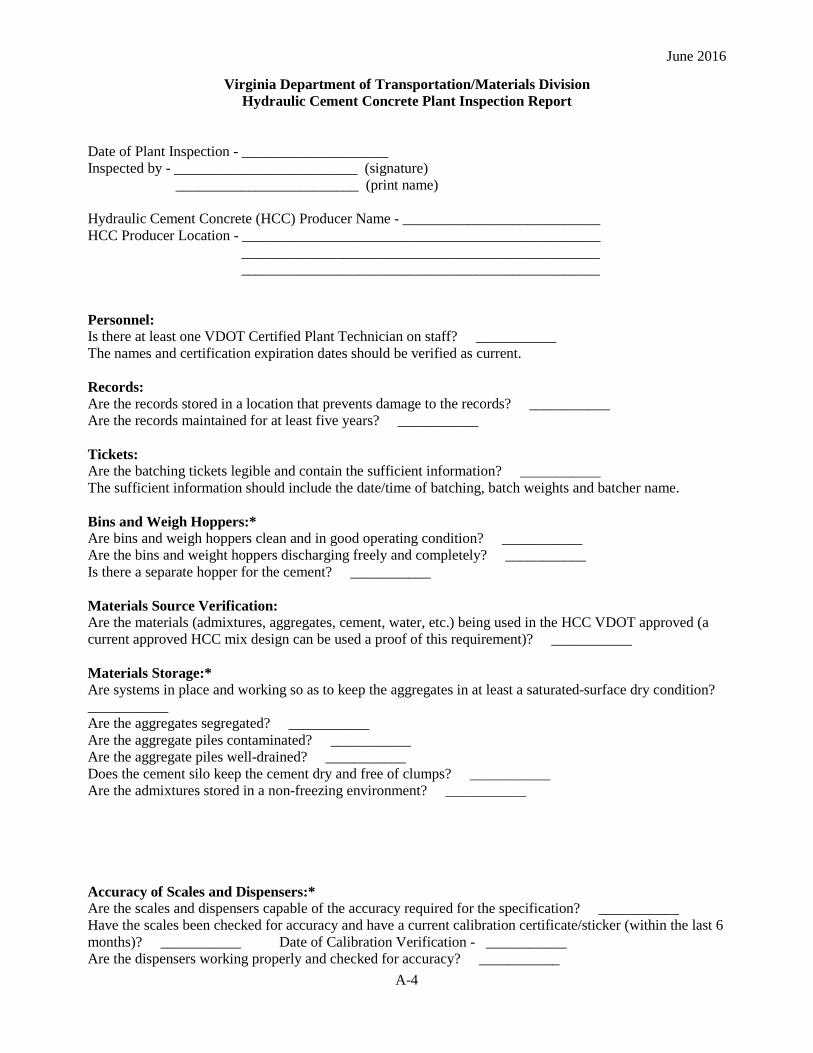
June 2016
Virginia Department of Transportation/Materials Division Hydraulic Cement Concrete Plant Inspection Report
Date of Plant Inspection - ____________________ Inspected by - _________________________ (signature) _________________________ (print name) Hydraulic Cement Concrete (HCC) Producer Name - ___________________________ HCC Producer Location - _________________________________________________ _________________________________________________ _________________________________________________ Personnel: Is there at least one VDOT Certified Plant Technician on staff? ___________ The names and certification expiration dates should be verified as current. Records: Are the records stored in a location that prevents damage to the records? ___________ Are the records maintained for at least five years? ___________ Tickets: Are the batching tickets legible and contain the sufficient information? ___________ The sufficient information should include the date/time of batching, batch weights and batcher name. Bins and Weigh Hoppers:* Are bins and weigh hoppers clean and in good operating condition? ___________ Are the bins and weight hoppers discharging freely and completely? ___________ Is there a separate hopper for the cement? ___________ Materials Source Verification: Are the materials (admixtures, aggregates, cement, water, etc.) being used in the HCC VDOT approved (a current approved HCC mix design can be used a proof of this requirement)? ___________ Materials Storage:* Are systems in place and working so as to keep the aggregates in at least a saturated-surface dry condition? ___________ Are the aggregates segregated? ___________ Are the aggregate piles contaminated? ___________ Are the aggregate piles well-drained? ___________ Does the cement silo keep the cement dry and free of clumps? ___________ Are the admixtures stored in a non-freezing environment? ___________
Accuracy of Scales and Dispensers:* Are the scales and dispensers capable of the accuracy required for the specification? ___________ Have the scales been checked for accuracy and have a current calibration certificate/sticker (within the last 6 months)? ___________ Date of Calibration Verification - ___________ Are the dispensers working properly and checked for accuracy? ___________
A-4
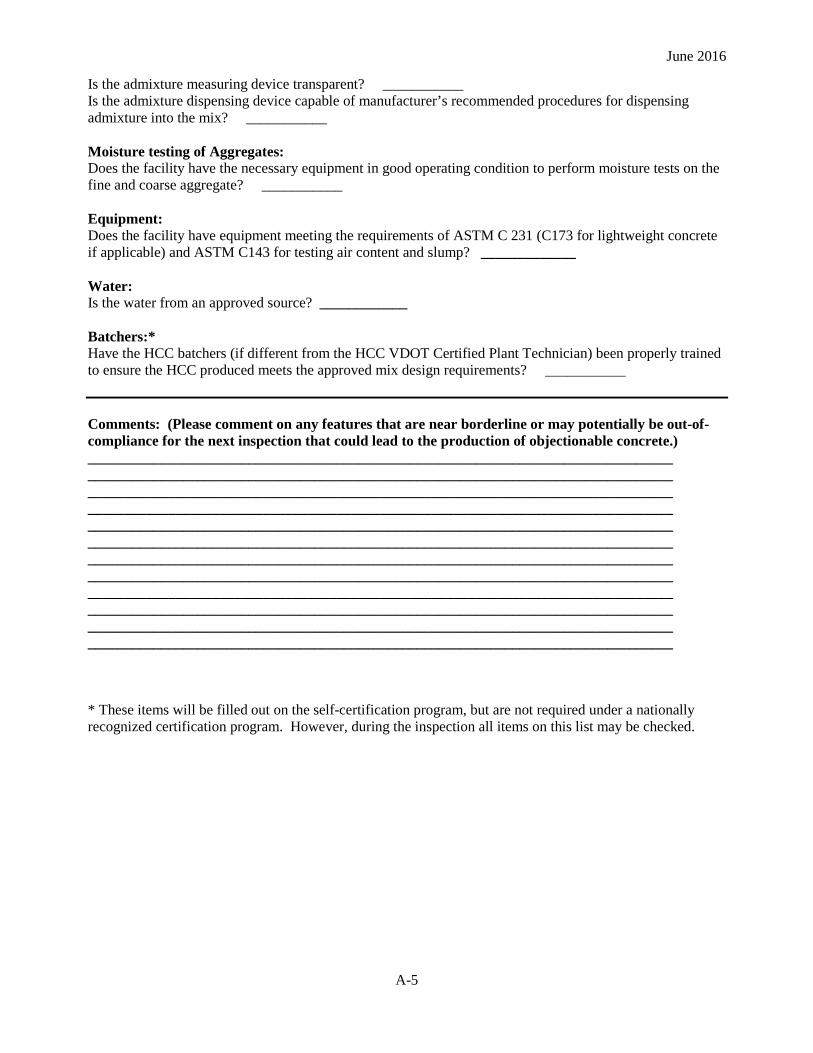
June 2016
Is the admixture measuring device transparent? ___________ Is the admixture dispensing device capable of manufacturer’s recommended procedures for dispensing admixture into the mix? ___________ Moisture testing of Aggregates: Does the facility have the necessary equipment in good operating condition to perform moisture tests on the fine and coarse aggregate? ___________ Equipment: Does the facility have equipment meeting the requirements of ASTM C 231 (C173 for lightweight concrete if applicable) and ASTM C143 for testing air content and slump? _____________ Water: Is the water from an approved source? ____________ Batchers:* Have the HCC batchers (if different from the HCC VDOT Certified Plant Technician) been properly trained to ensure the HCC produced meets the approved mix design requirements? ___________ Comments: (Please comment on any features that are near borderline or may potentially be out-of-compliance for the next inspection that could lead to the production of objectionable concrete.) ________________________________________________________________________________ ________________________________________________________________________________ ________________________________________________________________________________ ________________________________________________________________________________ ________________________________________________________________________________ ________________________________________________________________________________ ________________________________________________________________________________ ________________________________________________________________________________ ________________________________________________________________________________ ________________________________________________________________________________ ________________________________________________________________________________ ________________________________________________________________________________ * These items will be filled out on the self-certification program, but are not required under a nationally recognized certification program. However, during the inspection all items on this list may be checked.
A-5

June 2016
Appendix B: Latex Volumetric Mixer Calibration Procedure and Form
Volumetric Latex Truck Calibration For latex modified concrete overlays the use of a calibrated mobile mixer is required. Each mixer must be individually calibrated. In addition, they must be recalibrated every 6 months thereafter, and after any change in materials including a change in source. A mixer that is calibrated and accepted in one district may be accepted in another at the discretion of the District Materials Engineer, provided the same materials are being used.
The calibration process is based on an approved mix design submitted by the contractor for the locally selected aggregates in Saturated Surface Dry (SSD) condition. The dry weight ratio of cement/fine aggregate/coarse aggregate in the SSD condition is approximately 1/2.5/2 with a latex modifier content of 3.5 gallons (13.25 L) per bag. The calibration counts are based on the discharge time for one 94 lbs. (42.64 kg) bag of cement. Check that all scales and instruments used for weighing are approved and have current calibrations. Payment will be based upon the total number of calibrated counts. A recording meter, visible at all times and equipped with a ticket printout, should indicate the calibrated measurement.
The following data and calculations should be recorded on the Concrete Mobile Calibration Data Sheet referred to as the “worksheet” hereafter and found at the end of this section.
(a) Cement A “Plate Count” is recorded on the worksheet in the box provided. The “Plate Count” is the value recorded on the manufacturer’s plate and has been determined by the manufacturer to be the cement feeder meter count to discharge one 94 lbs. (100 kg) unit or bag of cement.
Step 1:
The first step in the calibration procedure is to determine the amount of time and counts it takes to discharge one bag (94 lbs. or 42.64 kg) of cement. Select a container that can suitably hold the 94 lbs. (42.64 kg) of cement and determine the weight of the container when empty. Record the empty container weight. Place the container under the chute of the mobile mixer and discharge an estimated 94 lbs. (42.64 kg) of cement while noting the meter count and the time in seconds. Weigh the full container. The weight of cement equals the weight of the container and cement minus the weight of the container. If the cement weight is within tolerance of 0 to + 4% (94 to 98 lbs.) (42.64 to 44.45 kg), then record the noted time and count data on the calibration worksheet. If the weight of cement is not within tolerance, then the gate valve must be readjusted until the tolerance is met. This procedure must be repeated until five sequentially acceptable results (the weight of cement is within the 94 to 98 lbs. or 42.64 to 44.45 kg tolerance) are recorded (weight in lbs., counts and time in seconds).
Step 2:
Total the Weights, Counts and Times columns individually. Transfer the Total Weights (A), Total Counts (B) and Total Times (C) to the calculating boxes.
Step 3:
The average number of counts per bag (94 lbs. or 42.64 kg) of cement is calculated by:
D = B / A
Where,
B-1
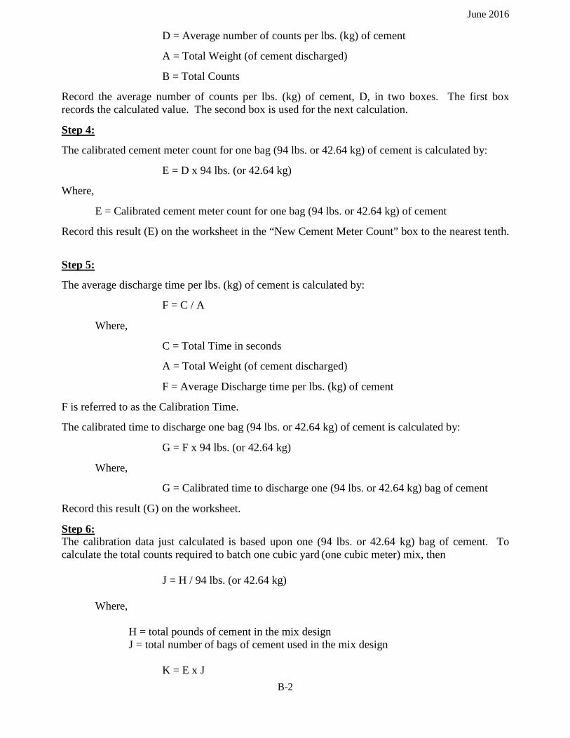
June 2016
D = Average number of counts per lbs. (kg) of cement
A = Total Weight (of cement discharged)
B = Total Counts
Record the average number of counts per lbs. (kg) of cement, D, in two boxes. The first box records the calculated value. The second box is used for the next calculation.
Step 4:
The calibrated cement meter count for one bag (94 lbs. or 42.64 kg) of cement is calculated by:
E = D x 94 lbs. (or 42.64 kg)
Where,
E = Calibrated cement meter count for one bag (94 lbs. or 42.64 kg) of cement
Record this result (E) on the worksheet in the “New Cement Meter Count” box to the nearest tenth.
Step 5:
The average discharge time per lbs. (kg) of cement is calculated by:
F = C / A
Where,
C = Total Time in seconds
A = Total Weight (of cement discharged)
F = Average Discharge time per lbs. (kg) of cement
F is referred to as the Calibration Time.
The calibrated time to discharge one bag (94 lbs. or 42.64 kg) of cement is calculated by:
G = F x 94 lbs. (or 42.64 kg)
Where,
G = Calibrated time to discharge one (94 lbs. or 42.64 kg) bag of cement
Record this result (G) on the worksheet.
Step 6: The calibration data just calculated is based upon one (94 lbs. or 42.64 kg) bag of cement. To calculate the total counts required to batch one cubic yard
(one cubic meter) mix, then
J = H / 94 lbs. (or 42.64 kg) Where, H = total pounds of cement in the mix design
J = total number of bags of cement used in the mix design K = E x J
B-2
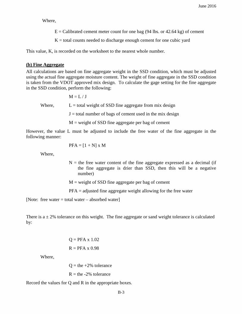
June 2016
Where,
E = Calibrated cement meter count for one bag (94 lbs. or 42.64 kg) of cement
K = total counts needed to discharge enough cement for one cubic yard This value, K, is recorded on the worksheet to the nearest whole number.
(b) Fine Aggregate All calculations are based on fine aggregate weight in the SSD condition, which must be adjusted using the actual fine aggregate moisture content. The weight of fine aggregate in the SSD condition is taken from the VDOT approved mix design. To calculate the gage setting for the fine aggregate in the SSD condition, perform the following:
M = L / J
Where, L = total weight of SSD fine aggregate from mix design
J = total number of bags of cement used in the mix design
M = weight of SSD fine aggregate per bag of cement
However, the value L must be adjusted to include the free water of the fine aggregate in the following manner:
PFA = [1 + N] x M
Where,
N = the free water content of the fine aggregate expressed as a decimal (if the fine aggregate is drier than SSD, then this will be a negative number)
M = weight of SSD fine aggregate per bag of cement
PFA = adjusted fine aggregate weight allowing for the free water
[Note: free water = total water – absorbed water]
There is a ± 2% tolerance on this weight. The fine aggregate or sand weight tolerance is calculated by:
Q = PFA x 1.02
R = PFA x 0.98
Where,
Q = the +2% tolerance
R = the -2% tolerance
Record the values for Q and R in the appropriate boxes.
B-3
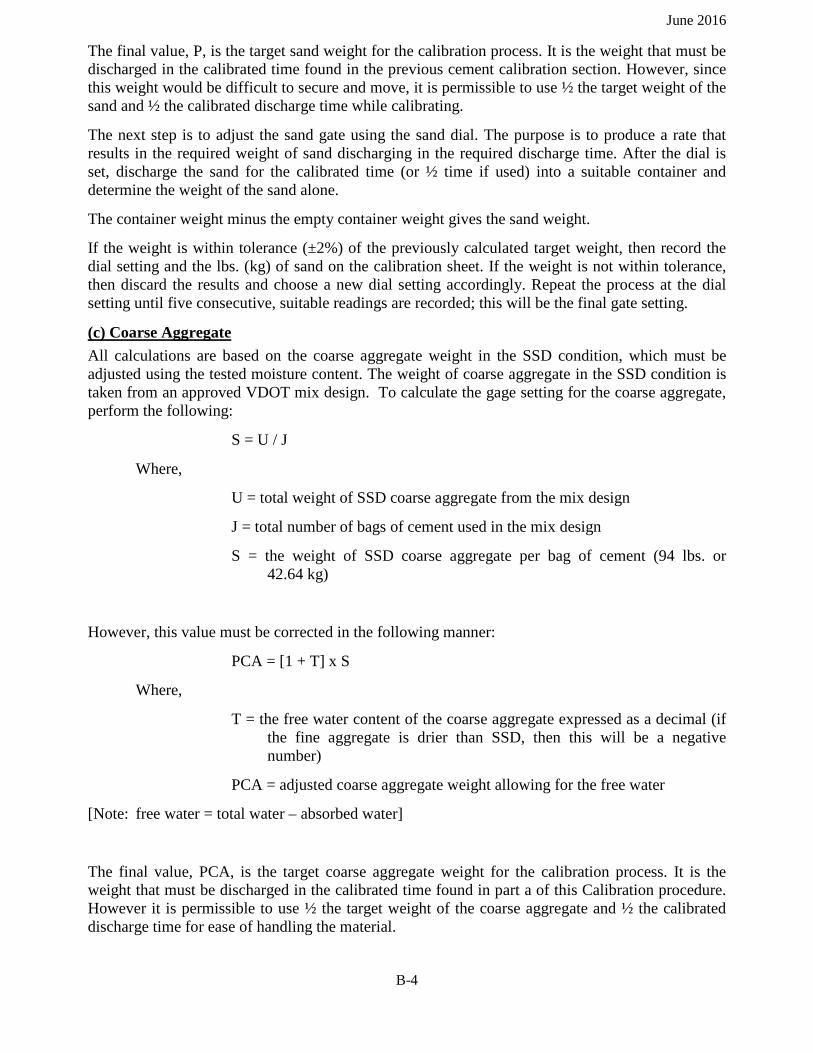
June 2016
The final value, P, is the target sand weight for the calibration process. It is the weight that must be discharged in the calibrated time found in the previous cement calibration section. However, since this weight would be difficult to secure and move, it is permissible to use ½ the target weight of the sand and ½ the calibrated discharge time while calibrating.
The next step is to adjust the sand gate using the sand dial. The purpose is to produce a rate that results in the required weight of sand discharging in the required discharge time. After the dial is set, discharge the sand for the calibrated time (or ½ time if used) into a suitable container and determine the weight of the sand alone.
The container weight minus the empty container weight gives the sand weight.
If the weight is within tolerance (±2%) of the previously calculated target weight, then record the dial setting and the lbs. (kg) of sand on the calibration sheet. If the weight is not within tolerance, then discard the results and choose a new dial setting accordingly. Repeat the process at the dial setting until five consecutive, suitable readings are recorded; this will be the final gate setting.
(c) Coarse Aggregate All calculations are based on the coarse aggregate weight in the SSD condition, which must be adjusted using the tested moisture content. The weight of coarse aggregate in the SSD condition is taken from an approved VDOT mix design. To calculate the gage setting for the coarse aggregate, perform the following:
S = U / J
Where,
U = total weight of SSD coarse aggregate from the mix design
J = total number of bags of cement used in the mix design
S = the weight of SSD coarse aggregate per bag of cement (94 lbs. or 42.64 kg)
However, this value must be corrected in the following manner:
PCA = [1 + T] x S
Where,
T = the free water content of the coarse aggregate expressed as a decimal (if the fine aggregate is drier than SSD, then this will be a negative number)
PCA = adjusted coarse aggregate weight allowing for the free water
[Note: free water = total water – absorbed water]
The final value, PCA, is the target coarse aggregate weight for the calibration process. It is the weight that must be discharged in the calibrated time found in part a of this Calibration procedure. However it is permissible to use ½ the target weight of the coarse aggregate and ½ the calibrated discharge time for ease of handling the material.
B-4
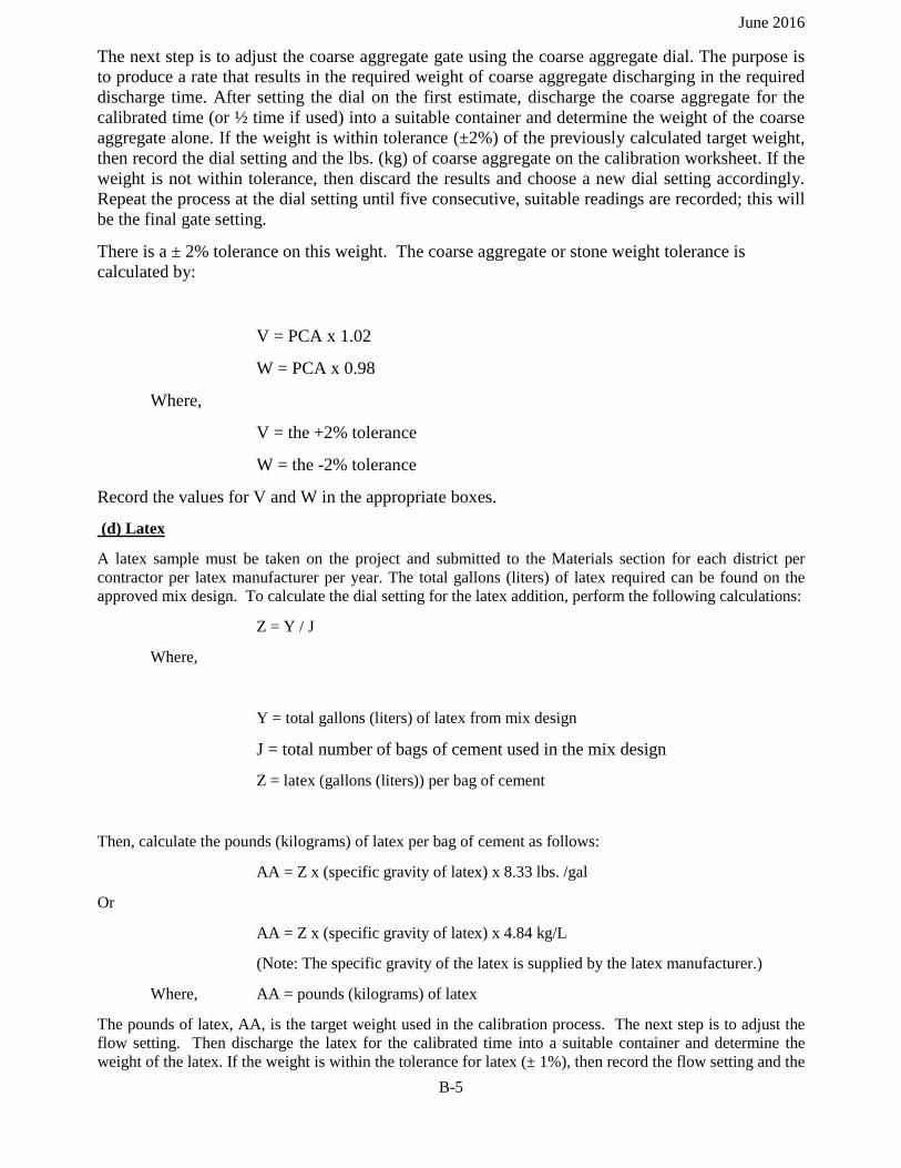
June 2016
The next step is to adjust the coarse aggregate gate using the coarse aggregate dial. The purpose is to produce a rate that results in the required weight of coarse aggregate discharging in the required discharge time. After setting the dial on the first estimate, discharge the coarse aggregate for the calibrated time (or ½ time if used) into a suitable container and determine the weight of the coarse aggregate alone. If the weight is within tolerance (±2%) of the previously calculated target weight, then record the dial setting and the lbs. (kg) of coarse aggregate on the calibration worksheet. If the weight is not within tolerance, then discard the results and choose a new dial setting accordingly. Repeat the process at the dial setting until five consecutive, suitable readings are recorded; this will be the final gate setting.
There is a ± 2% tolerance on this weight. The coarse aggregate or stone weight tolerance is calculated by:
V = PCA x 1.02
W = PCA x 0.98
Where,
V = the +2% tolerance
W = the -2% tolerance
Record the values for V and W in the appropriate boxes.
(d) Latex
A latex sample must be taken on the project and submitted to the Materials section for each district per contractor per latex manufacturer per year. The total gallons (liters) of latex required can be found on the approved mix design. To calculate the dial setting for the latex addition, perform the following calculations:
Z = Y / J
Where,
Y = total gallons (liters) of latex from mix design
J = total number of bags of cement used in the mix design
Z = latex (gallons (liters)) per bag of cement
Then, calculate the pounds (kilograms) of latex per bag of cement as follows:
AA = Z x (specific gravity of latex) x 8.33 lbs. /gal
Or
AA = Z x (specific gravity of latex) x 4.84 kg/L
(Note: The specific gravity of the latex is supplied by the latex manufacturer.)
Where, AA = pounds (kilograms) of latex
The pounds of latex, AA, is the target weight used in the calibration process. The next step is to adjust the flow setting. Then discharge the latex for the calibrated time into a suitable container and determine the weight of the latex. If the weight is within the tolerance for latex (± 1%), then record the flow setting and the
B-5

June 2016
weight of the latex. If it is not within tolerance, discard the results and adjust the dial setting accordingly. Repeat the process at the dial setting until five consecutive, suitable readings are recorded; this will be the final dial setting.
Calculate the ± 1% tolerance on the weight of the latex as follows:
BB = AA x 1.01
CC = AA x 0.99
Where,
BB = the +1% tolerance
CC = the -1% tolerance
Record the values for BB and CC in the appropriate boxes.
(e) Water
From the approved mix design, obtain the total number of gallons (L) of water required. Then perform the following calculations:
EE = DD / J
Where, DD = total gallons of water from the approved mix design
J = total number of bags of cement used in the mix design
EE = the water in gallons (liters) per bag of cement
This value, EE, must be adjusted based on the free water in the aggregates as follows:
FF = EE - ((M x N)/8.33) – ((S x T)/8.33) (in lbs. /gal)
or
FF = EE - ((M x N)/4.84) – ((S x T)/4.84) (in kg/L)
Where,
FF = the water in gallons (liters) per bag of cement adjusted for the aggregate free water
This value must be adjusted for the water in the latex as follows:
GG = FF – (Z x (1 – (percent solids in latex supplied by manufacturer expressed as a decimal)))
Where,
GG = the water in gallons per bag of cement used in the calibration adjusted for the aggregate free water and the water in the latex
To calculate the gallons into lbs. (kg) per bag of cement (that has already been adjusted for the aggregate free water and the water contributed by the latex,
HH = GG / 8.33 lbs. /gal or HH = GG / 4.84 kg/L
Where,
B-6
June 2016
GG = the water in gallons per bag of cement used in the calibration adjusted for the aggregate free water and the water in the latex
HH = the pounds of water per bag of cement to be used in the calibration process.
The next step is to adjust the water flow setting. After setting the flow rate, discharge the water for the calibrated time, G, and determine the weight of the water. If the weight is within the ± 1% tolerance, then record the flow setting and the weight of the water. If it is not within tolerance, discard the results, adjust the dial setting and repeat this step. Once an acceptable weight is determined, this process is repeated at the dial setting until five sequentially acceptable readings are recorded.
Calculate the ± 1% tolerance on water weight as follows:
II = HH x 1.01
JJ = HH x 0.99
Where,
HH = the pounds of water per bag of cement to be used in the calibration process.
II = the +1% tolerance
JJ = the -1% tolerance
Record the values for II and JJ in the appropriate boxes.
(f) Yield Test The Contractor shall perform a yield test:
• per truck per day of batching
• prior to deck placement for each mixing unit
• when a unit is moved from the job site for recharging
• when the source of stockpiled materials is changed and
• when there is reason to believe the calibration may be erroneous.
The box must be built to a volume of ¼ yd3 (0.20 m
3) A common set of box dimensions is 3′ x 3′ x 9″ (1.0 m
x 1.0 m x 0.20 m). The first step in the process is to batch a load of concrete using the previously determined calibration settings and total counts.
Note that for anything other than a one yd3 (one m
3) batch, the total counts must be adjusted accordingly. For
example, a ¼ yd3 (0.25 m
3) batch would require ¼ the total counts. Calculate the adjusted total counts for the
yield box being used and record the result on the bottom of the worksheet.
The box should then be completely filled with concrete while noting the total number of counts used. This value must be within ± 1% of the calibrated counts that was determined earlier. If it is within tolerance, then it becomes the new calibrated total count. If the yield does not fall within the required range, the calibration process must be redone.
B-7
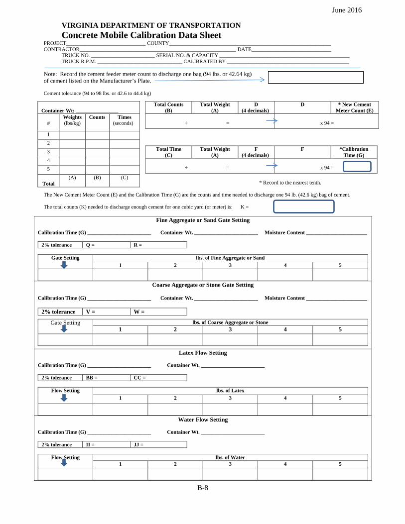
June 2016
VIRGINIA DEPARTMENT OF TRANSPORTATION Concrete Mobile Calibration Data Sheet
PROJECT______________________________ COUNTY_____________________________________________________________ CONTRACTOR___________________________________________________________ DATE______________________________
TRUCK NO. ________________________ SERIAL NO. & CAPACITY _________________________________________________ TRUCK R.P.M. ________________________________ CALIBRATED BY ______________________________________________
Note: Record the cement feeder meter count to discharge one bag (94 lbs. or 42.64 kg) of cement listed on the Manufacturer’s Plate. Cement tolerance (94 to 98 lbs. or 42.6 to 44.4 kg)
* Record to the nearest tenth.
The New Cement Meter Count (E) and the Calibration Time (G) are the counts and time needed to discharge one 94 lb. (42.6 kg) bag of cement. The total counts (K) needed to discharge enough cement for one cubic yard (or meter) is: K =
Fine Aggregate or Sand Gate Setting
Calibration Time (G) ________________________ Container Wt. ________________________ Moisture Content _______________________
2% tolerance Q = R =
Gate Setting lbs. of Fine Aggregate or Sand 1 2 3 4 5
Coarse Aggregate or Stone Gate Setting
Calibration Time (G) ________________________ Container Wt. ________________________ Moisture Content _______________________
2% tolerance V = W =
Gate Setting lbs. of Coarse Aggregate or Stone 1 2 3 4 5
Latex Flow Setting
Calibration Time (G) ________________________ Container Wt. ________________________
2% tolerance BB = CC =
Flow Setting lbs. of Latex 1 2 3 4 5
Water Flow Setting
Calibration Time (G) ________________________ Container Wt. ________________________
2% tolerance II = JJ =
Flow Setting lbs. of Water 1 2 3 4 5
Container Wt: ________________
#
Weights (lbs/kg)
Counts Times (seconds)
1 2 3 4 5
Total (A) (B) (C)
Total Counts (B)
Total Weight (A)
D (4 decimals)
D * New Cement Meter Count (E)
÷ =
x 94 =
Total Time (C)
Total Weight (A)
F (4 decimals)
F *Calibration Time (G)
÷ =
x 94 =
B-8
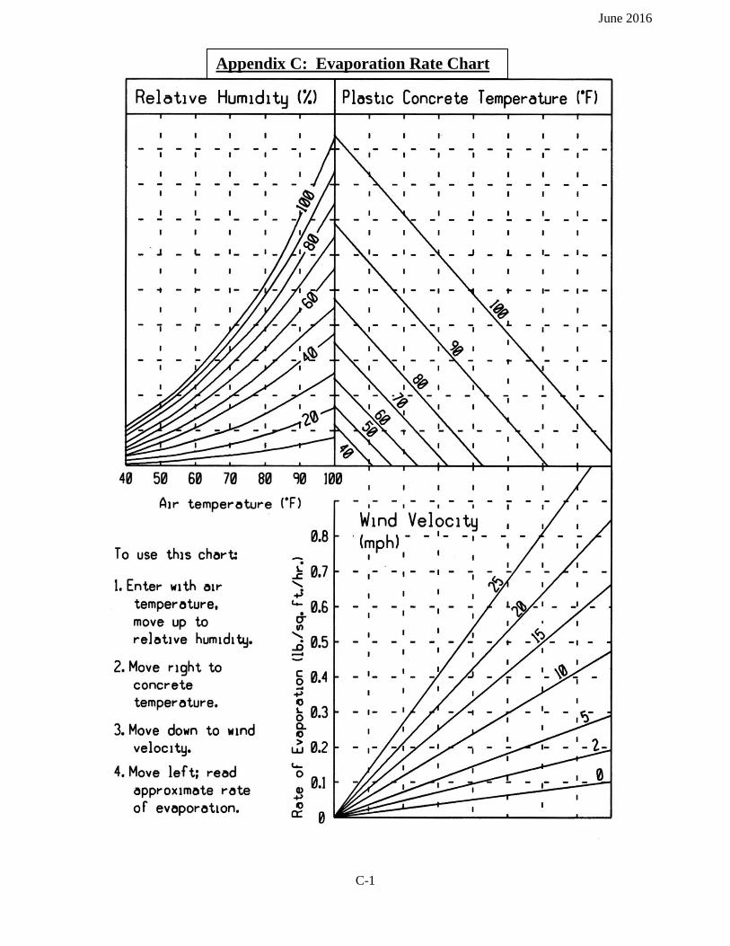
June 2016
Appendix C: Evaporation Rate Chart
C-1

June 2016
Appendix D: Definitions of Terms and Abbreviations
Abrasion Resistance of an Aggregate – The ability of an aggregate to resist polishing. Absolute Volume - The volume of a material without voids. Absorbed Water – The water within the pores and capillaries of an aggregate. Accelerator – A chemical used to “speed up” the setting time of concrete. Acceptance Testing (AT) - to determine if the quality of produced material meets specification. Acidic Water – Water containing concentrations of hydrochloric (muriatic), sulfuric or other common acid that results in a pH of less than 7.0. Aggregate – An inert filler material such as crushed stone, gravel or sand that is mixed with cement, water and admixtures to make concrete. Air-dry – A condition where an aggregate particle is dry to the surface, but contains some water within its pores. Air-entraining agent – A chemical admixture that is added to a concrete mix to incorporate microscopic air voids in the hardened concrete. Air-entrained concrete – Concrete that has had an air-entraining admixture added to incorporate minute air bubbles distributed uniformly throughout the cement mortar. Alkali - Alkali-Silica Reaction (ASR) - ASR is a reaction between the alkalies in concrete and reactive silica in aggregates causing expansion and usually indicated by cracks in concrete. Cement is the principal source of the alkalies in concrete. There are several ways of controlling ASR: use low alkali cement, use non-reactive aggregates, keep the hardened concrete dry, and/or mitigate the reaction with mineral admixtures. Mitigation of the reaction using mineral admixtures is the most practical approach for control given the materials available for use in Virginia.
The method of measurement of potential expansion of the cementitious materials is by ASTM C-227, which uses borosilicate glass as the reactive aggregate. The 56 day results are used, since the results of the test are inconclusive at 14 and 28 days. The VCTIR has determined that the expansion of the samples should be limited to a maximum of 0.15%.
Certain combinations of cement/mineral admixture have been found to be effective based on the alkali content of the cement. These minimum quantities are tabulated in the VRBS, Section 217.02(a). Approval of other mineral admixture blends or new mineral admixtures not listed in this table may be obtained from the Department by furnishing test results that demonstrate effectiveness. The effectiveness testing should be performed with a minimum of three control cements having alkali contents, spread across the range from 0.5 to 1.0%, and test mixtures containing the proportion of mineral admixture requested. These test values should be normalized in accordance with Equation 5 in VTRC 95-R21 - Use of Fly Ash, Slag, or Silica Fume to Inhibit Alkali-Silica Reactivity by D. Stephen Lane and H. Celik Ozyildirim.
Alkaline Water – Water that contains concentrations of sodium hydroxide, potassium hydroxide or other substance having marked basic properties that results in a pH of greater than 7.0. Bleed Water – A condition where excess mixing water migrates to the surface plastic concrete due to the settlement and consolidation. Cement – A powder of alumina, silica, line, iron oxide and magnesia burned together in a kiln and finely pulverized and used as a binder in making concrete. Often calcium sulfate (gypsum) is added to adjust the time of set.
D-1
June 2016
Cement Fineness - The particle size to which cement is ground. The fineness of cement affects the hydration. As the cement fineness increases (cement particles become smaller), the rate of cement hydration increases and causes an acceleration in strength development. Chemical Admixture – a chemical added to HCC to affect at least one or more properties such as the air content, the time of set, the consistency, etc. Coarse Aggregate – Aggregate larger than ¼ inch in diameter retained on a No. 4 sieve, often referred to as gravel or stone. Consistency – A condition of plastic concrete which relates to its cohesion, wetness or flowability. The consistency is typically measured by the slump test. CPM – VDOT Materials Division’s Concrete Program Manager. Curing Compound - A liquid material that may be spray-applied or applied with a brush or roller to the surface of fresh HCC to minimize water loss during the early stages of setting and hardening. White, pigmented (usually titanium dioxide) curing compound is used in hot weather to reduce the surface temperature of the HCC. Non-pigmented curing compound typically has a fugitive dye added. The fugitive dye dissipates soon after application when exposed to sunlight. Deleterious Materials or Deleterious Substances in Aggregates – Undesirable substances that may be found in aggregates. These harmful substances include organic impurities, silty clay, coal, lignite and certain lightweight and soft particles. Dry-Rodded Unit Weight – The density (such as pounds per cubic foot, pcf) of dry aggregate compacted in a container of known volume by rodding in three layers. Durability – The ability of hardened concrete to resist deterioration caused by weathering (freezing, thawing, heating, cooling, wetting, drying, etc.), chemicals and abrasion. Dyed HCC – HCC with a surface dye added after the concrete is placed and finished (not very durable) or the dye is integrally mixed during the mixing operation. A special provision is usually added to the contract when dyed HCC is specified/desired. The color of dyed HCC typically fades with prolonged exposure to sunlight. Exposed Aggregate Surface – HCC surface that is prepared by placing and finishing followed by an application of set retarder to the surface. After approximately 8 to 24 hours (depending upon the strength gain of the HCC mix) the uncured surface paste is washed away with a low-pressure water stream. Aggregates are exposed on the surface. Usually, brown or tan No. 8 river gravel is used as the coarse aggregate. The quantity of coarse aggregate is usually increased from the ACI mix design method with quantity of the cement paste being decreased. Exposed aggregate surfaces are typically used for aesthetic purposes. Before the invention of truncated dome surfaces, exposed aggregate surfaces were used on curb cut ramps to assist the visually impaired. A special provision is usually inserted in a contract when an exposed aggregate surface is required/desired. False Set – A significant loss of plasticity shortly after the concrete is mixed. Fine Aggregate – A natural silica or manufactured aggregate passing a ¼ inch sieve opening (No. 4 sieve), normally referred to as sand. Fineness of Cement – (see Cement Fineness) Fineness Modulus – An index to the coarseness or fineness of an aggregate. The Fineness Modulus (F.M.) is calculated using the gradation analysis by adding the cumulative percentages retained on standard sieves and dividing by 100. The standard sieves are 6” (142.64 mm), 3” (75 mm), 1 ½” (37.5 mm), ¾” (19.0 mm), 3/8” (9.5 mm), No. 4 (4.75 mm), No. 8 (2.36 mm), No. 16 (1.18 mm), No. 30 (600 µm), No. 42.64 (300 µm) and No. 100 (142.64 µm). For VDOT work the maximum sieve size used for the FM of fine aggregate is No. 8. Material retained on or passing the No. 200 sieve is not used in calculating the F.M. The F. M. is reported to the nearest 0.01. The F.M. should not be less than 2.3 and not more than 3.1 or vary by more than 0.20 from batch to
D-2
June 2016
batch of concrete. The F. M. along with the fine aggregate specific gravity is used to obtain the percentage of coarse aggregate used in the American Concrete Institute (ACI) mix design process. Free Water – The moisture on the surface of an aggregate. The amount of free water is calculated by subtracting the absorbed water from the total water. Freeze-Thaw Resistance of an Aggregate – The ability of an aggregate to retain its structural stability when subjected to the freezing and thawing conditions with water. An aggregate’s ability to resist deterioration due to freezing and thawing is related to an aggregate’s porosity, absorption and pore structure. Gradation of an Aggregate - The distribution of various particle size fractions in an aggregate. The gradation is determined by passing an aggregate through a series of nested sieves. The amount of aggregate retained on each sieve is weighed and compared mathematically to the total weight of the aggregate being tested. Gypsum – (CaSO4 ·2H2O) calcium sulfate dihydrate or hydrous calcium sulfate. Gypsum is added to cement during production to control the setting time of cement. Harsh Mix – A coarse mix which is difficult to place and finish. A harsh mix typically does not contain enough fine aggregate to provide a dense, workable mix. A harsh mix segregates easily because it is not cohesive. HCC – hydraulic cement concrete. Heat of Hydration – The heat generated when cement and water react chemically. IAS – Independent Assurance Sampling or IA Sampling. Refer to the VDOT MOI, Chapter II, Section 202.04. Independent Assurance (IA) - to evaluate the accuracy of acceptance sampling and testing, operations and equipment by an independent party not responsible for QC or acceptance testing. Mineral Admixture - a finely divided siliceous or siliceous/aluminum material that reacts chemically with cement and water to reduce HCC permeability. Mineral admixtures include Fly Ash, ground-granulated blast furnace slag, silica fume and metakaolin. Miscellaneous HCC - Miscellaneous HCC includes all concrete except pavement, prestressed and structural HCC. MOI – VDOT Materials Division’s Manual of Instructions. Plastic Concrete – The condition of HCC is workable before it reaches initial set. Plastic Shrinkage Cracking – random cracking (like the drying mud cracks at the edge of a river or pond) in HCC that occurs when the evaporation rate exceeds the bleed rate. Pozzolan – A finely divided siliceous or siliceous/aluminum material (currently referred to as a mineral admixture) that reacts chemically with cement and water to reduce HCC permeability. QA - Quality Assurance. QC - Quality Control. Set Retarder – A material composed of (1) calcium, sodium, potassium or ammonium salt of lignosulfonic acid, (2) hydroxlyated carboxylic acid or its salt, or (3) carbohydrates, except sucrose. The purpose of a set retarder is to delay the setting time of concrete. Retarders provide a lubricating effect and may also function as a water reducing agent. Setting Time – The time it takes a cement paste to begin hardening. Sieve Analysis – A process in which an aggregate is separated into its various sizes by passing the aggregate through a series of screens of various size openings for the purpose of determine the distribution of the quantities separated. Slump Test – a test performed in accordance with ASTM C143 used to determine the consistency (relative fluidity or mobility) of the HCC mixture. The slump test (often referred to as simply “slump” does not measure the water content or workability of HCC.
D-3
June 2016
Soundness of a Hardened Cement Paste – The ability of a hardened cement paste to retain its volume after setting. Specific Gravity – The ration of the weight of a given volume of material to the weight of an equal volume of water (both being at the same temperature). Structural HCC - Structural HCC is considered to be bridges, box culverts, retaining walls and foundations for overhead signs, signal poles, lighting poles, and other specialty items that require working drawings. Total Water – The sum of the moisture on the surface and the moisture absorbed into the pores and capillaries of an aggregate. Verification Sampling and Testing (VST) – to validate the quality of the product by comparing results to specification. VTRC – The Virginia Transportation Research Counsel is the research branch of VDOT in association with the University of Virginia in cooperation with the Virginia Institute of Technology. VRBS – The Virginia Department of Transportation’s Road and Bridge Specifications. If a date is not stipulated, the most current date is specified by default. VST – Verification Sampling and Testing, see above. Water – An ingredient in a concrete mix that reacts chemically with cement. This reaction is called hydration. Water also provides the necessary workability for the concrete. Water-Cement Ratio (w/c ratio) – The ratio of the amount of water to the amount of cement in a concrete mix. This ratio is typically expressed as a decimal by weight. Given all other conditions are constant, increasing the w/c ratio decreases HCC strength. Generally, for each gallon of water added to a cubic yard of concrete, the HCC strength will be reduced from 2.5 to 3%. Water-Reducing Admixture – A chemical used for the purpose of reducing the quantity of mix water in concrete. This additive will cause an increase in slump and workability when added to a concrete mix of a given consistency. Well-Graded Aggregate – An aggregate which contains a uniform percentage retained on each standard sieve. The gradation change is uniform from coarse to fine particles. Workability – The property of freshly mixed concrete which is the ease or difficulty in placing and finishing concrete. “Good Workability” means that the concrete may be placed and finished with little difficulty and the mix contains a uniform gradation of aggregates. Yield - the volume of concrete produced, in cubic yards (cubic meters), as determined by dividing the total weight of all materials included in the batch, by the weight of the HCC as determined by unit weight test. To calculate the yield, refer to ASTM C138.
D-4
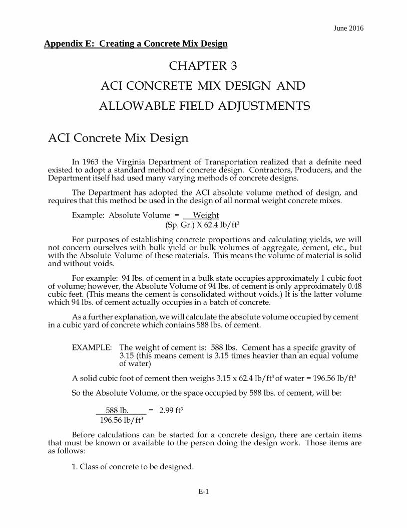
June 2016
Appendix E: Creating a Concrete Mix Design
CHAPTER 3
ACI CONCRETE MIX DESIGN AND
ALLOWABLE FIELD ADJUSTMENTS
ACI Concrete Mix Design
In 1963 the Virginia Department of Transportation realized that a defi nite need existed to adopt a standard method of concrete design. Contractors, Producers, and the Department itself had used many varying methods of concrete designs.
The Department has adopted the ACI absolute volume method of design, and
requires that this method be used in the design of all normal weight concrete mixes.
Example: Absolute Volume = Weight (Sp. Gr.) X 62.4 lb/ft3
For purposes of establishing concrete proportions and calculating yields, we will
not concern ourselves with bulk yield or bulk volumes of aggregate, cement, etc., but with the Absolute Volume of these materials. This means the volume of material is solid and without voids.
For example: 94 lbs. of cement in a bulk state occupies approximately 1 cubic foot
of volume; however, the Absolute Volume of 94 lbs. of cement is only approximately 0.48 cubic feet. (This means the cement is consolidated without voids.) It is the latter volume which 94 lbs. of cement actually occupies in a batch of concrete.
As a further explanation, we will calculate the absolute volume occupied by cement
in a cubic yard of concrete which contains 588 lbs. of cement. EXAMPLE: The weight of cement is: 588 lbs. Cement has a specifi c gravity of
3.15 (this means cement is 3.15 times heavier than an equal volume of water)
A solid cubic foot of cement then weighs 3.15 x 62.4 lb/ft3 of water = 196.56 lb/ft3
So the Absolute Volume, or the space occupied by 588 lbs. of cement, will be:
588 lb. = 2.99 ft3
196.56 lb/ft3
Before calculations can be started for a concrete design, there are certain items that must be known or available to the person doing the design work. Those items are as follows:
1. Class of concrete to be designed.
E-1

June 2016
2. Fine aggregate: a. Specifi c gravity b. Fineness modulus
3. Coarse aggregate: a. Maximum size aggregate b. Specific Gravity c. Unit Weight (dry rodded unit weight)
4. From VDOT Specifications: a. Cement factor (minimum cement content)
b. W.C. ratio (maximum W/C ratio) c. Air content (mean air content) d. Nominal Maximum size aggregate
Other information ACI Table A1.5.3.6 (volume of coarse aggregate per unit
of volume of concrete) (Page 3-6) b.Type of cement and alkali content c. TL-27 (Concrete Mix Design Form)(Page 3-7) d. ACI Mix design work sheet may be used (Page 3-3) e. Source of all materials going into the mix
(For example purposes, the Fineness Modulus and Specific Gravity for all design problems in this study guide are taken from the Aggregate Data Sheets on Pages 3-32 and 3-33. For an updated list, please see the Aggregate Quality List, which is published annually in the Materials Division Manual of Instruction.)
HELPFUL CONVERSION FACTORS
One cubic foot of water = 7.5 gallons = 62.4 lbs. One bag of cement = 94 lbs. (42.6 kg) Specific gravity of cement is 3.15 Specific gravity x 62.4 = Absolute Volume 1.308 cubic yards = One cubic meter 1 gallon of water = 8.33 lbs. = 3.78 liters 1 gallon per yard = 5 liters per meter One cubic yard = 27 cubic feet One bag of cement = one cubic foot (loose volume) One bag of cement = 0.48 cubic feet (absolute volume)
E-2

June 2016
TABLE A1.5.3.6 VOLUME OF COARSE AGGREGATE PER UNIT OF VOLUME OF CONCRETE (SI)
Nominal Maximum Volume of dry-rodded coarse aggregate *
size of per unit volume of concrete for different Aggregate fineness moduli** of fine aggregate
Metric English
9.5 mm 3/8
12.5 mm
19.0 mm %
25.0 mm 1
37.5 mm 1
50 mm 2
75 mm 3
150 mm 6
2.40 2.50 2.60 2.70 2.80 2.90 3.00
0.50 0.49 0.48 0.47 0.46 0.45 0.44
0.59 0.58 0.57 0.56 0.55 0.54 0.53
0.66 0.65 0.64 0.63 0.62 0.61 0.60
0.71 0.70 0.69 0.68 0.67 0.66 0.65
0.75 0.74 0.73 0.72 0.71 0.70 0.69
0.78 0.77 0.76 0.75 0.74 0.73 0.72
0.82 0.81 0.80 0.79 0.78 0.77 0.76
0.87 0.86 0.85 0.84 0.83 0.82 0.81 * Volumes are based on aggregates in dry-rodded condition as described in ASTM C 29
** See ASTM Method 136 for calculation of fineness modulus
E-3
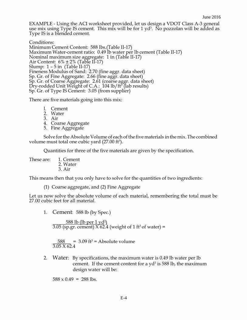
June 2016 EXAMPLE - Using the ACI worksheet provided, let us design a VDOT Class A-3 general use mix using Type IS cement. This mix will be for 1 yd3. No pozzolan will be added as Type IS is a blended cement.
Conditions: Minimum Cement Content: 588 lbs.(Table II-17) Maximum Water-cement ratio: 0.49 lb water per lb cement (Table II-17) Nominal maximum size aggregate: 1 in (Table II-17) Air Content: 6% ± 2% (Table II-17) Slump: 1 - 5 in (Table II-17) Fineness Modulus of Sand: 2.70 (fine aggr. data sheet) Sp. Gr. of Fine Aggregate: 2.66 (fine aggr. data sheet) Sp. Gr. of Coarse Aggregate: 2.61 (coarse aggr. data sheet) Dry-rodded Unit Weight of C.A.: 104 lb/ft3 (lab results) Sp. Gr. of Type IS Cement: 3.05 (from supplier)
There are five materials going into this mix:
l. Cement 2. Water 3. Air 4. Coarse Aggregate 5. Fine Aggregate
Solve for the Absolute Volume of each of the five materials in the mix. The combined
volume must total one cubic yard (27.00 ft3).
Quantities for three of the five materials are given by the specification.
These are: 1. Cement 2. Water 3. Air
This means then that you only have to solve for the quantities of two ingredients:
(1) Coarse aggregate, and (2) Fine Aggregate
Let us now solve the absolute volume of each material, remembering the total must be 27.00 cubic feet for all material.
1. Cement: 588 lb (by Spec.)
588 lb (lb per 1 yd3) 3.05 (sp.gr. cement) X 62.4 (weight of 1 ft3 of water) =
588 = 3.09 ft3 = Absolute volume 3.05 X 62.4
2. Water: By specifications, the maximum water is 0.49 lb water per lb
cement. If the cement content for a yd3 is 588 lb, the maximum design water will be:
588 x 0.49 = 288 lbs.
E-4
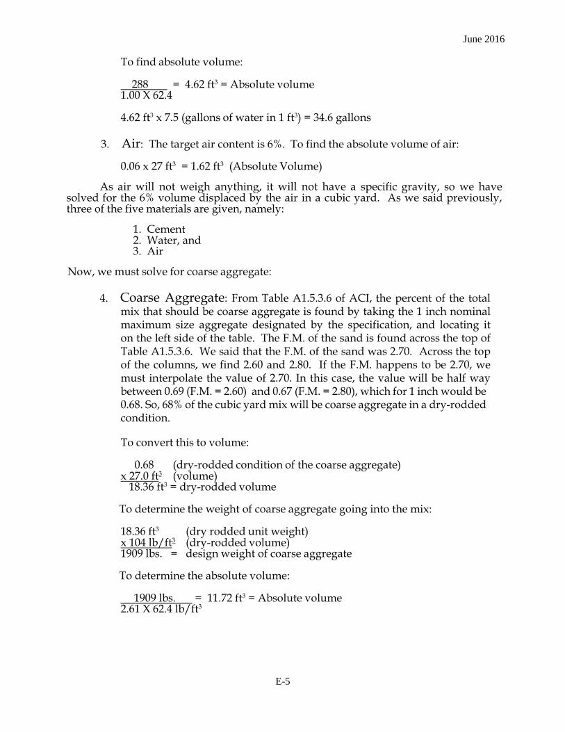
June 2016
To find absolute volume:
288 = 4.62 ft3 = Absolute volume 1.00 X 62.4
4.62 ft3 x 7.5 (gallons of water in 1 ft3) = 34.6 gallons
3. Air: The target air content is 6%. To find the absolute volume of air:
0.06 x 27 ft3 = 1.62 ft3 (Absolute Volume)
As air will not weigh anything, it will not have a specific gravity, so we have
solved for the 6% volume displaced by the air in a cubic yard. As we said previously, three of the five materials are given, namely:
1. Cement 2. Water, and 3. Air
Now, we must solve for coarse aggregate:
4. Coarse Aggregate: From Table A1.5.3.6 of ACI, the percent of the total mix that should be coarse aggregate is found by taking the 1 inch nominal maximum size aggregate designated by the specification, and locating it on the left side of the table. The F.M. of the sand is found across the top of Table A1.5.3.6. We said that the F.M. of the sand was 2.70. Across the top of the columns, we find 2.60 and 2.80. If the F.M. happens to be 2.70, we must interpolate the value of 2.70. In this case, the value will be half way between 0.69 (F.M. = 2.60) and 0.67 (F.M. = 2.80), which for 1 inch would be 0.68. So, 68% of the cubic yard mix will be coarse aggregate in a dry-rodded condition.
To convert this to volume:
0.68 (dry-rodded condition of the coarse aggregate)
x 27.0 ft3 (volume) 18.36 ft3 = dry-rodded volume
To determine the weight of coarse aggregate going into the mix:
18.36 ft3 (dry rodded unit weight) x 104 lb/ft3 (dry-rodded volume) 1909 lbs. = design weight of coarse aggregate
To determine the absolute volume:
1909 lbs. = 11.72 ft3 = Absolute volume 2.61 X 62.4 lb/ft3
E-5
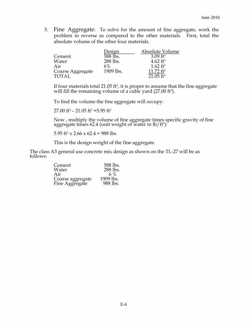
June 2016
5. Fine Aggregate: To solve for the amount of fine aggregate, work the problem in reverse as compared to the other materials. First, total the absolute volume of the other four materials.
Design Absolute Volume Cement 588 lbs. 3.09 ft3 Water 288 lbs. 4.62 ft3 Air 6% 1.62 ft3 Coarse Aggregate 1909 lbs. 11.72 ft3 TOTAL 21.05 ft3
If four materials total 21.05 ft3, it is proper to assume that the fine aggregate will fill the remaining volume of a cubic yard (27.00 ft3).
To find the volume the fine aggregate will occupy:
27.00 ft3 - 21.05 ft3 =5.95 ft3
Now , multiply the volume of fine aggregate times specific gravity of fine aggregate times 62.4 (unit weight of water in lb/ft3):
5.95 ft3 x 2.66 x 62.4 = 988 lbs.
This is the design weight of the fine aggregate. The class A3 general use concrete mix design as shown on the TL-27 will be as follows:
Cement 588 lbs. Water 288 lbs. Air 6 % Coarse aggregate 1909 lbs. Fine Aggregate 988 lbs.
E-6
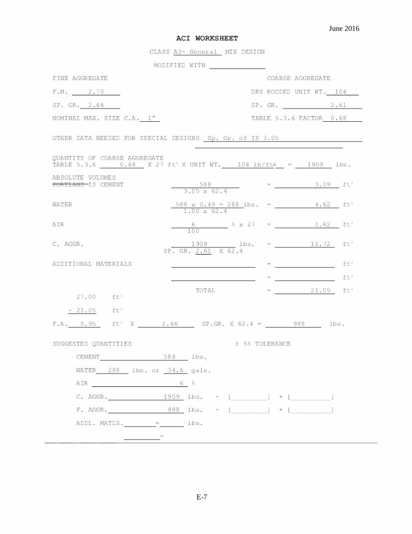
June 2016
E-7
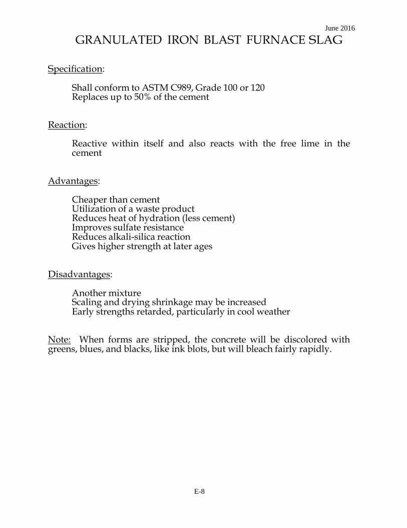
June 2016
GRANULATED IRON BLAST FURNACE SLAG Specification:
Shall conform to ASTM C989, Grade 100 or 120 Replaces up to 50% of the cement
Reaction:
Reactive within itself and also reacts with the free lime in the cement
Advantages:
Cheaper than cement Utilization of a waste product Reduces heat of hydration (less cement) Improves sulfate resistance Reduces alkali-silica reaction Gives higher strength at later ages
Disadvantages:
Another mixture Scaling and drying shrinkage may be increased Early strengths retarded, particularly in cool weather
Note: When forms are stripped, the concrete will be discolored with greens, blues, and blacks, like ink blots, but will bleach fairly rapidly.
E-8
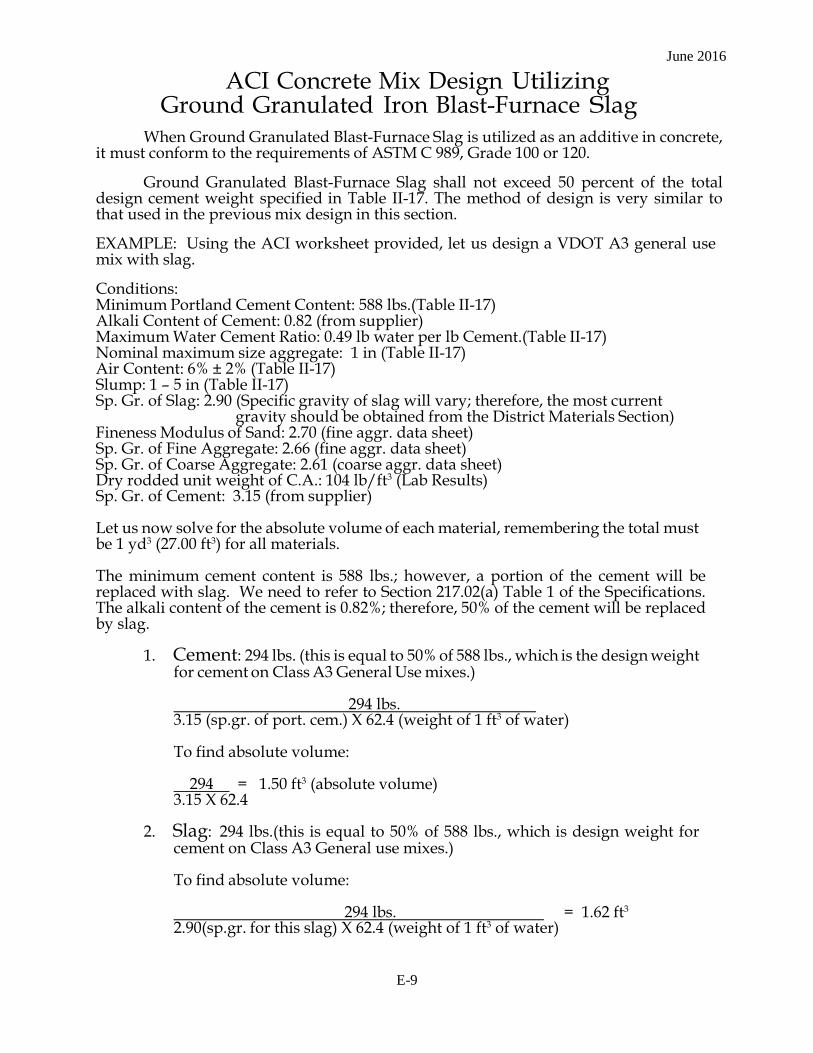
June 2016
ACI Concrete Mix Design Utilizing Ground Granulated Iron Blast-Furnace Slag
When Ground Granulated Blast-Furnace Slag is utilized as an additive in concrete,
it must conform to the requirements of ASTM C 989, Grade 100 or 120.
Ground Granulated Blast-Furnace Slag shall not exceed 50 percent of the total design cement weight specified in Table II-17. The method of design is very similar to that used in the previous mix design in this section.
EXAMPLE: Using the ACI worksheet provided, let us design a VDOT A3 general use mix with slag.
Conditions: Minimum Portland Cement Content: 588 lbs.(Table II-17) Alkali Content of Cement: 0.82 (from supplier) Maximum Water Cement Ratio: 0.49 lb water per lb Cement.(Table II-17) Nominal maximum size aggregate: 1 in (Table II-17) Air Content: 6% ± 2% (Table II-17) Slump: 1 - 5 in (Table II-17) Sp. Gr. of Slag: 2.90 (Specific gravity of slag will vary; therefore, the most current
gravity should be obtained from the District Materials Section) Fineness Modulus of Sand: 2.70 (fine aggr. data sheet) Sp. Gr. of Fine Aggregate: 2.66 (fine aggr. data sheet) Sp. Gr. of Coarse Aggregate: 2.61 (coarse aggr. data sheet) Dry rodded unit weight of C.A.: 104 lb/ft3 (Lab Results) Sp. Gr. of Cement: 3.15 (from supplier)
Let us now solve for the absolute volume of each material, remembering the total must be 1 yd3 (27.00 ft3) for all materials.
The minimum cement content is 588 lbs.; however, a portion of the cement will be replaced with slag. We need to refer to Section 217.02(a) Table 1 of the Specifications. The alkali content of the cement is 0.82%; therefore, 50% of the cement will be replaced by slag.
1. Cement: 294 lbs. (this is equal to 50% of 588 lbs., which is the design weight
for cement on Class A3 General Use mixes.)
294 lbs. 3.15 (sp.gr. of port. cem.) X 62.4 (weight of 1 ft3 of water)
To find absolute volume:
294 = 1.50 ft3 (absolute volume) 3.15 X 62.4
2. Slag: 294 lbs.(this is equal to 50% of 588 lbs., which is design weight for
cement on Class A3 General use mixes.)
To find absolute volume:
294 lbs. = 1.62 ft3
2.90(sp.gr. for this slag) X 62.4 (weight of 1 ft3 of water)
E-9

June 2016
3. Water: By specifications, the maximum water is 0.49 lb water per lb.
cementitious material. For this mix, you would consider the cementitious weight to be: 294 lbs. Cement + 294 lbs. Slag = 588 lbs.
588 x 0.49 = 288 lbs.
To find absolute volume:
288 = 4.62 ft3 = Absolute Volume 1.00 x 62.4
4.62 ft3 x 7.5 (gallons of water in 1 ft3) = 34.6 gallons
4. Air: The target air content is 6%. To find the absolute volume of air:
0.06 x 27 ft3 = 1.62 ft3 = Absolute Volume
As air will not weigh anything, it will not have a specific gravity, so we have solved for the 6% volume displaced by the air in a cubic yard.
5. Coarse Aggregate: A factor of 0.68 is obtained from Table A1.5.3.6 of ACI
by using the Fineness Modulus of the sand and the nominal maximum size of the coarse aggregate in the method described on Page 3-10. To convert this to volume, we say 0.68 x 27 ft3 = 18.36 ft3 (this volume is dry rodded). With the dry rodded unit weight given as 104 lb/ft3, determine the weight of coarse aggregate going into the mix by the following:
18.36 ft3 x 104 lb/ft3 = 1909 lbs. (design wt. of C.A.)
The specific gravity of the coarse aggregate was 2.61. The absolute volume is determined by the following:
1909 lbs. = 11.72 ft3 = Absolute Volume 2.61 X 62.4 (wt. of ft3 of water)
6. Fine Aggregate: To solve for the amount of fine aggregate, work the
problem in reverse as compared to the other materials. First, total the absolute volume of the other five materials:
Design Absolute Volume
Cement 294 lbs. 1.50 ft3 Slag 294 lbs. 1.62 ft3 Water 288 lbs. 4.62 ft3 Air 6 % 1.62 ft3 Coarse Aggr. 1909 lbs. 11.72 ft3 TOTAL 21.08 ft3
E-10
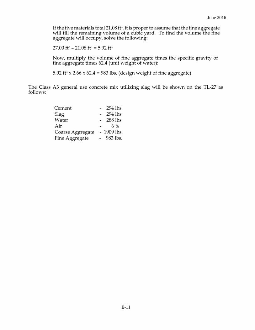
June 2016
If the five materials total 21.08 ft3, it is proper to assume that the fine aggregate will fill the remaining volume of a cubic yard. To find the volume the fine aggregate will occupy, solve the following:
27.00 ft3 - 21.08 ft3 = 5.92 ft3
Now, multiply the volume of fine aggregate times the specific gravity of fine aggregate times 62.4 (unit weight of water):
5.92 ft3 x 2.66 x 62.4 = 983 lbs. (design weight of fine aggregate)
The Class A3 general use concrete mix utilizing slag will be shown on the TL-27 as follows:
Cement - 294 lbs. Slag - 294 lbs. Water - 288 lbs. Air - 6 % Coarse Aggregate - 1909 lbs. Fine Aggregate - 983 lbs.
E-11
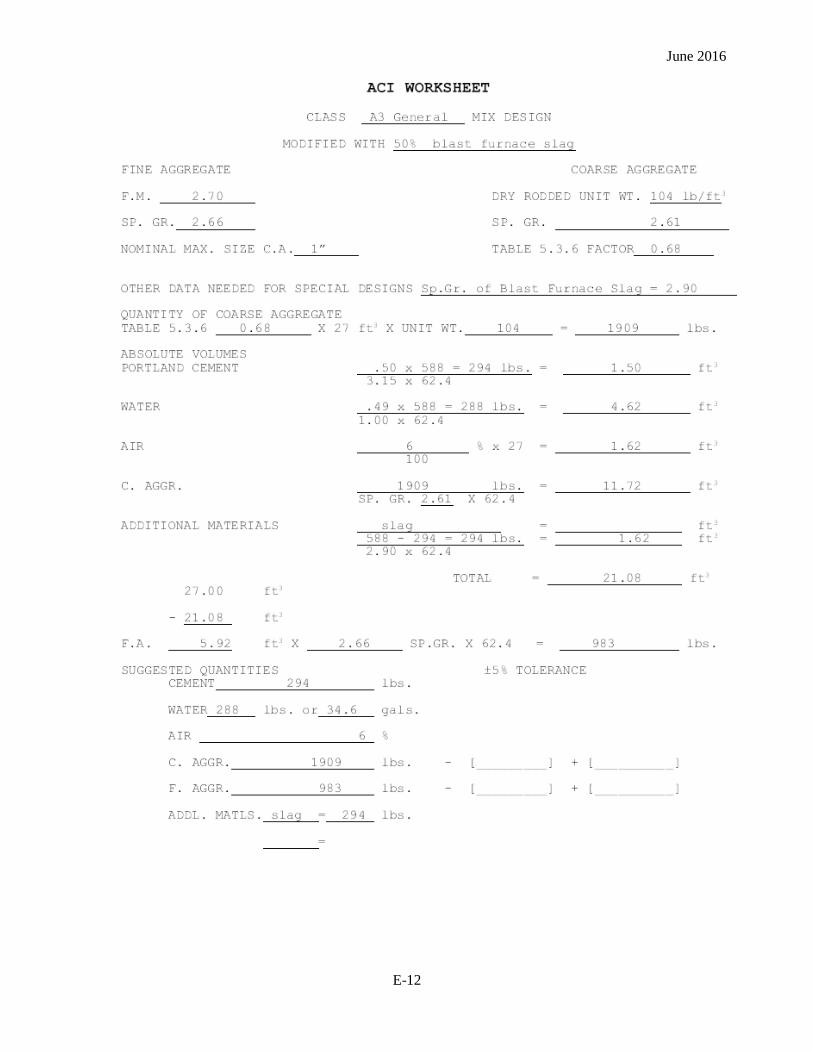
June 2016
E-12
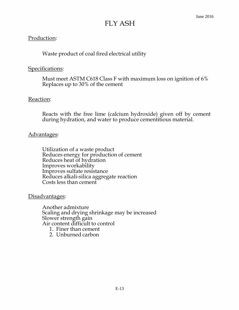
June 2016
FLY ASH Production:
Waste product of coal fired electrical utility Specifications:
Must meet ASTM C618 Class F with maximum loss on ignition of 6% Replaces up to 30% of the cement
Reaction:
Reacts with the free lime (calcium hydroxide) given off by cement during hydration, and water to produce cementitious material.
Advantages:
Utilization of a waste product Reduces energy for production of cement Reduces heat of hydration Improves workability Improves sulfate resistance Reduces alkali-silica aggregate reaction Costs less than cement
Disadvantages:
Another admixture Scaling and drying shrinkage may be increased Slower strength gain Air content difficult to control
1. Finer than cement 2. Unburned carbon
E-13

June 2016
ACI Concrete Mix Design Utilizing Fly Ash
When fly ash is utilized as an additive in concrete, it must conform to the requirements of ASTM C618 Class F or Class C, except that the Loss on Ignition shall be limited to a maximum of 6%. Class F, fly ash shall replace 20 to 30% by weight of the design cement depending on the alkali content of the cement used. The minimum total cementitious materials are specified in Table II-17. The method of design is very similar to that used in the previous mix designs in this chapter.
EXAMPLE: Using the ACI worksheet provided, let us design a VDOT Class A3 General mix using fly ash.
Conditions: Minimum Cement Content: 588 lbs. (Table II-17) Alkali Content of Cement: 0.65% (from supplier) Maximum Water-Cement ratio: 0.49 lbs. water per lb. cement (Table II-17) Nominal Maximum Size Aggregate: 1 in (Table II-17) Air Content : 6% ± 2% (Table II-17) Slump: 1 - 5" (Table II-17) Sp. Gr. of fly ash: 2.25 (Specific gravity of fly ash will vary. The most current gravity
from the manufacturer/supplier should be used). Fineness Modulus of Sand: 2.70 (fine aggr. data sheet) Sp. Gr. of Fine Aggregate: 2.66 (fine aggr. data sheet) Sp. Gr. of Coarse Aggregate: 2.61 (coarse aggr. data sheet) Dry-rodded Unit Weight of C.A.: 104 lb/ft3 (lab results) Sp.Gr. of Cement: 3.15 (from supplier)
Let us now solve the absolute volume of each material, remembering the total must be 27.00 ft3 for all materials.
The minimum cement content is 588 lbs.; however, a portion of the cement will be replaced with fly ash. We need to refer to Section 217.02(a) Table 1 of the Specifications. The alkali content of the cement is 0.65%; therefore, 20% of the cement will be replaced by fly ash.
1. Cement: 470 lbs. (this is equal to 80% of 588 lbs., which is the design wt.
of cement of a Class A3 General Mix).
470 lbs. (this is design weight for 1 yd3) 3.15 (sp.gr. of cement) X 62.4(weight of 1 ft3 of water)
470 lbs. = 2.39 ft3 Absolute volume 3.15 X 62.4
2. Fly ash: 118 lbs. (this is equal to 20% of 588 lbs., which is design wt. for
cement of a Class A3 General use mix).
To find absolute volume:
118 lbs. = 0.84 ft3
2.25(sp.gr.for this fly ash)X 62.4(weight of 1 ft3 of water)
E-14
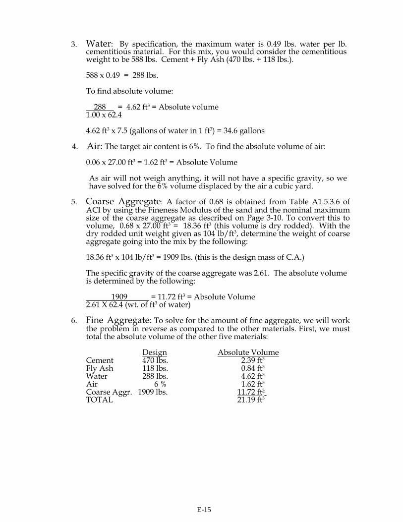
Water: By specification, the maximum water is 0.49 lbs. water per lb. 3. cementitious material. For this mix, you would consider the cementitious weight to be 588 lbs. Cement + Fly Ash (470 lbs. + 118 lbs.).
588 x 0.49 = 288 lbs.
To find absolute volume:
288 = 4.62 ft3 = Absolute volume 1.00 x 62.4
4.62 ft3 x 7.5 (gallons of water in 1 ft3) = 34.6 gallons
4. Air: The target air content is 6%. To find the absolute volume of air:
0.06 x 27.00 ft3 = 1.62 ft3 = Absolute Volume
As air will not weigh anything, it will not have a specific gravity, so we have solved for the 6% volume displaced by the air a cubic yard.
5. Coarse Aggregate: A factor of 0.68 is obtained from Table A1.5.3.6 of
ACI by using the Fineness Modulus of the sand and the nominal maximum size of the coarse aggregate as described on Page 3-10. To convert this to volume, 0.68 x 27.00 ft3 = 18.36 ft3 (this volume is dry rodded). With the dry rodded unit weight given as 104 lb/ft3, determine the weight of coarse aggregate going into the mix by the following:
18.36 ft3 x 104 lb/ft3 = 1909 lbs. (this is the design mass of C.A.)
The specific gravity of the coarse aggregate was 2.61. The absolute volume is determined by the following:
1909 = 11.72 ft3 = Absolute Volume 2.61 X 62.4 (wt. of ft3 of water)
6. Fine Aggregate: To solve for the amount of fine aggregate, we will work
the problem in reverse as compared to the other materials. First, we must total the absolute volume of the other five materials:
Design Absolute Volume
Cement 470 lbs. 2.39 ft3 Fly Ash 118 lbs. 0.84 ft3 Water 288 lbs. 4.62 ft3 Air 6 % 1.62 ft3 Coarse Aggr. 1909 lbs. 11.72 ft3 TOTAL 21.19 ft3
E-15
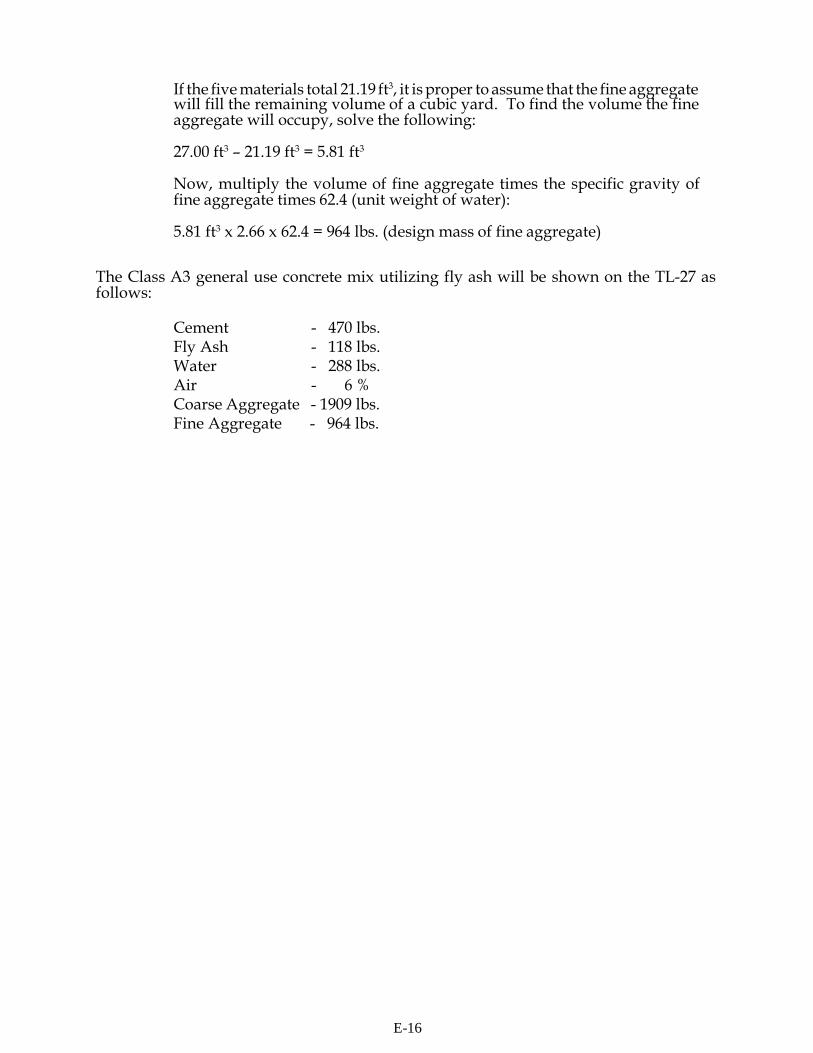
If the five materials total 21.19 ft3, it is proper to assume that the fine aggregate will fill the remaining volume of a cubic yard. To find the volume the fine aggregate will occupy, solve the following:
27.00 ft3 - 21.19 ft3 = 5.81 ft3
Now, multiply the volume of fine aggregate times the specific gravity of fine aggregate times 62.4 (unit weight of water):
5.81 ft3 x 2.66 x 62.4 = 964 lbs. (design mass of fine aggregate)
The Class A3 general use concrete mix utilizing fly ash will be shown on the TL-27 as follows:
Cement - 470 lbs. Fly Ash - 118 lbs. Water - 288 lbs. Air - 6 % Coarse Aggregate - 1909 lbs. Fine Aggregate - 964 lbs.
E-16
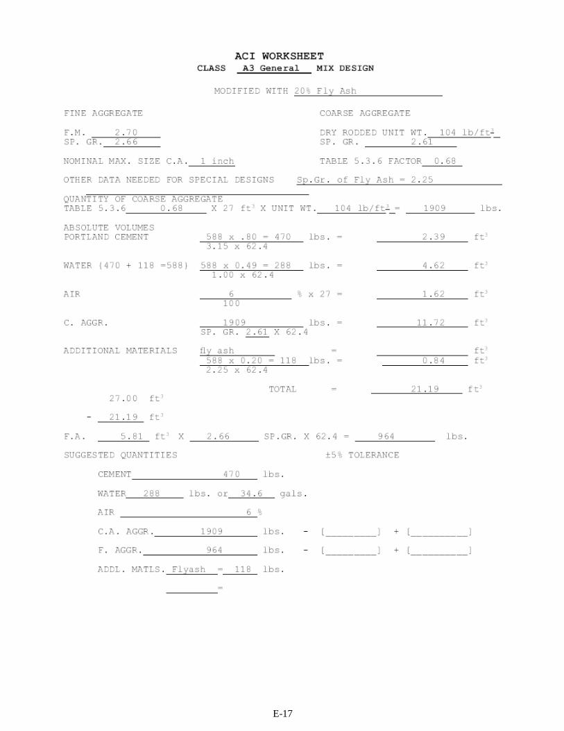
JJune
E-17
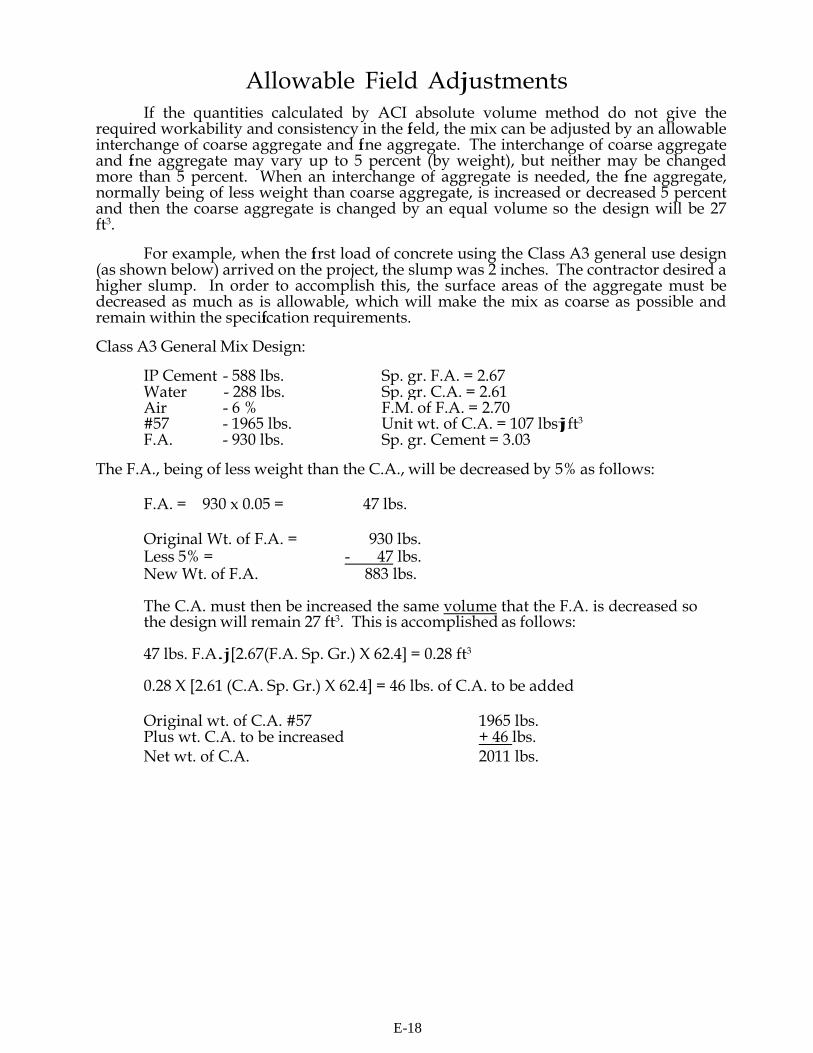
JJune
Allowable Field Adjustments
If the quantities calculated by ACI absolute volume method do not give the required workability and consistency in the fi eld, the mix can be adjusted by an allowable interchange of coarse aggregate and fi ne aggregate. The interchange of coarse aggregate and fi ne aggregate may vary up to 5 percent (by weight), but neither may be changed more than 5 percent. When an interchange of aggregate is needed, the fi ne aggregate, normally being of less weight than coarse aggregate, is increased or decreased 5 percent and then the coarse aggregate is changed by an equal volume so the design will be 27 ft3.
For example, when the fi rst load of concrete using the Class A3 general use design (as shown below) arrived on the project, the slump was 2 inches. The contractor desired a higher slump. In order to accomplish this, the surface areas of the aggregate must be decreased as much as is allowable, which will make the mix as coarse as possible and remain within the specifi cation requirements.
Class A3 General Mix Design:
IP Cement - 588 lbs. Sp. gr. F.A. = 2.67 Water - 288 lbs. Sp. gr. C.A. = 2.61 Air - 6 % F.M. of F.A. = 2.70 #57 - 1965 lbs. Unit wt. of C.A. = 107 lbsjft3 F.A. - 930 lbs. Sp. gr. Cement = 3.03
The F.A., being of less weight than the C.A., will be decreased by 5% as follows:
F.A. = 930 x 0.05 = 47 lbs.
Original Wt. of F.A. = 930 lbs. Less 5% = - 47 lbs. New Wt. of F.A. 883 lbs.
The C.A. must then be increased the same volume that the F.A. is decreased so the design will remain 27 ft3. This is accomplished as follows:
47 lbs. F.A.j[2.67(F.A. Sp. Gr.) X 62.4] = 0.28 ft3
0.28 X [2.61 (C.A. Sp. Gr.) X 62.4] = 46 lbs. of C.A. to be added
Original wt. of C.A. #57 1965 lbs. Plus wt. C.A. to be increased + 46 lbs. Net wt. of C.A. 2011 lbs.
E-18

The adjusted design quantities are:
Cement 588 lbs. Air 6 % Water 288 lbs. #57 2011 lbs. F.A. 883 lbs.
After these adjustments are made, the design should be checked to make sure it yields 27.00 ft3
Absolute Volume (ft3)
IP Cement - 588 lbs. 588 = 3.11
3.03 X 62.4
Air - 6% 0.06 X 27 = 1.62
Water - 288 lbs. 288 = 4.62
1.00 X 62.4
C. A. - #57 = 2011 lbs. 2011 = 12.35 2.61 X 62.4
F. A. - 883 lbs. 883 = 5.30
2.67 X 62.4
TOTAL 27.00
E-19
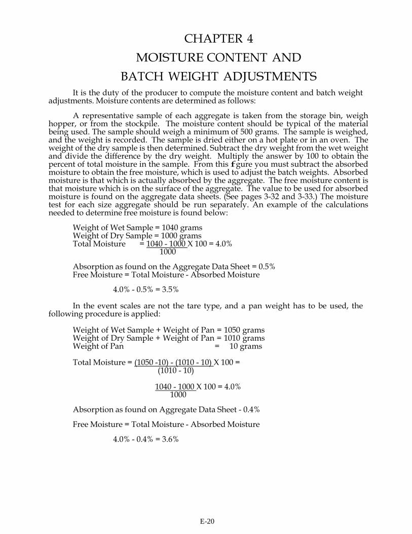
CHAPTER 4
MOISTURE CONTENT AND BATCH WEIGHT ADJUSTMENTS
It is the duty of the producer to compute the moisture content and batch weight adjustments. Moisture contents are determined as follows:
A representative sample of each aggregate is taken from the storage bin, weigh
hopper, or from the stockpile. The moisture content should be typical of the material being used. The sample should weigh a minimum of 500 grams. The sample is weighed, and the weight is recorded. The sample is dried either on a hot plate or in an oven. The weight of the dry sample is then determined. Subtract the dry weight from the wet weight and divide the difference by the dry weight. Multiply the answer by 100 to obtain the percent of total moisture in the sample. From this f gure you must subtract the absorbed moisture to obtain the free moisture, which is used to adjust the batch weights. Absorbed moisture is that which is actually absorbed by the aggregate. The free moisture content is that moisture which is on the surface of the aggregate. The value to be used for absorbed moisture is found on the aggregate data sheets. (See pages 3-32 and 3-33.) The moisture test for each size aggregate should be run separately. An example of the calculations needed to determine free moisture is found below:
Weight of Wet Sample = 1040 grams Weight of Dry Sample = 1000 grams Total Moisture = 1040 - 1000 X 100 = 4.0%
1000
Absorption as found on the Aggregate Data Sheet = 0.5% Free Moisture = Total Moisture - Absorbed Moisture
4.0% - 0.5% = 3.5%
In the event scales are not the tare type, and a pan weight has to be used, the
following procedure is applied:
Weight of Wet Sample + Weight of Pan = 1050 grams Weight of Dry Sample + Weight of Pan = 1010 grams Weight of Pan = 10 grams
Total Moisture = (1050 -10) - (1010 - 10) X 100 =
(1010 - 10)
1040 - 1000 X 100 = 4.0% 1000
Absorption as found on Aggregate Data Sheet - 0.4%
Free Moisture = Total Moisture - Absorbed Moisture
4.0% - 0.4% = 3.6%
E-20
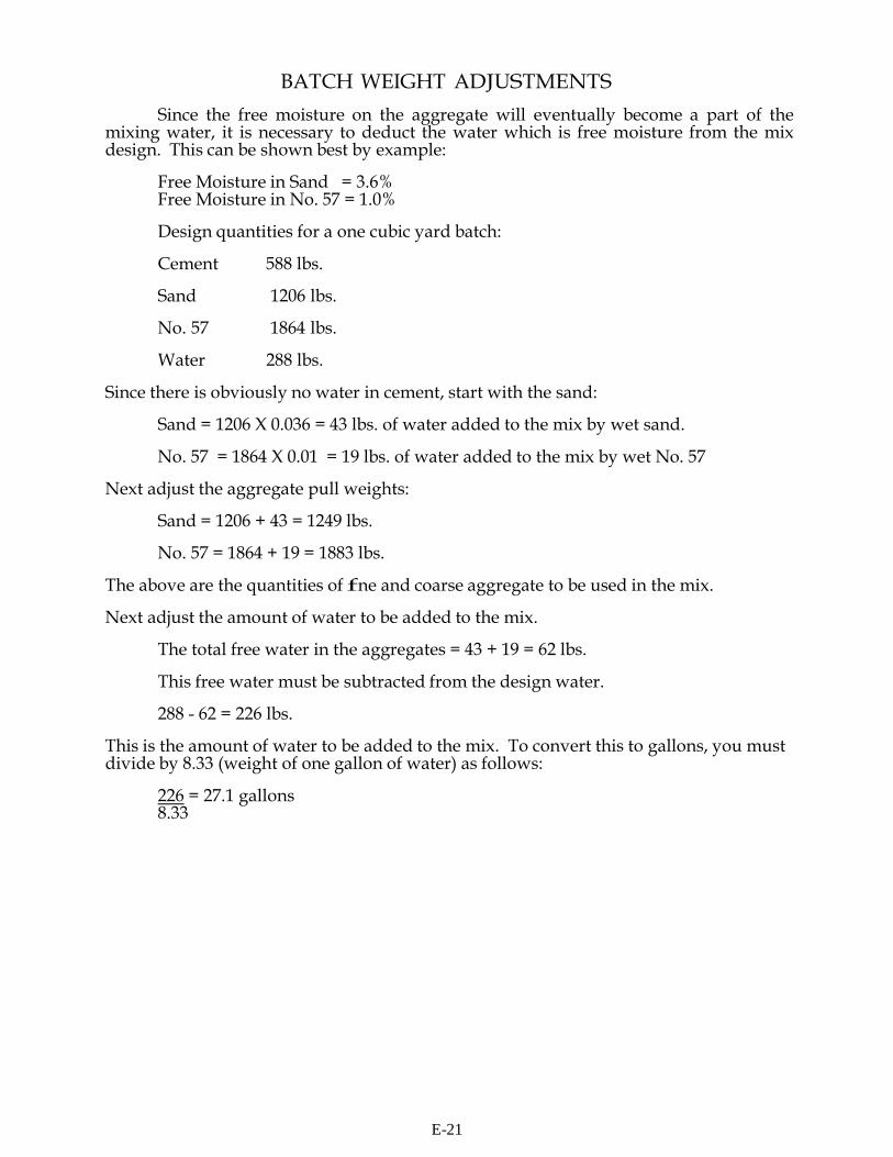
BATCH WEIGHT ADJUSTMENTS
Since the free moisture on the aggregate will eventually become a part of the mixing water, it is necessary to deduct the water which is free moisture from the mix design. This can be shown best by example:
Free Moisture in Sand = 3.6% Free Moisture in No. 57 = 1.0%
Design quantities for a one cubic yard batch:
Cement 588 lbs.
Sand 1206 lbs.
No. 57 1864 lbs.
Water 288 lbs.
Since there is obviously no water in cement, start with the sand:
Sand = 1206 X 0.036 = 43 lbs. of water added to the mix by wet sand.
No. 57 = 1864 X 0.01 = 19 lbs. of water added to the mix by wet No. 57
Next adjust the aggregate pull weights:
Sand = 1206 + 43 = 1249 lbs.
No. 57 = 1864 + 19 = 1883 lbs.
The above are the quantities of fne and coarse aggregate to be used in the mix.
Next adjust the amount of water to be added to the mix.
The total free water in the aggregates = 43 + 19 = 62 lbs.
This free water must be subtracted from the design water.
288 - 62 = 226 lbs. This is the amount of water to be added to the mix. To convert this to gallons, you must divide by 8.33 (weight of one gallon of water) as follows:
226 = 27.1 gallons 8.33
E-21
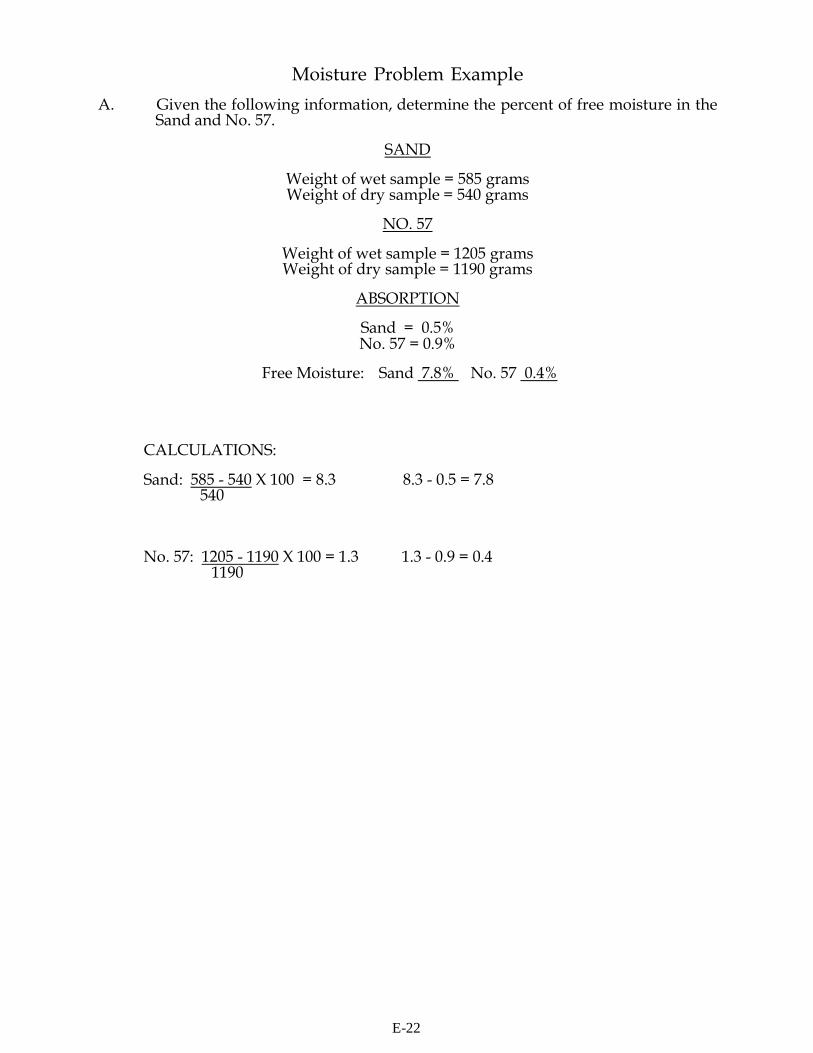
Moisture Problem Example
A. Given the following information, determine the percent of free moisture in the Sand and No. 57.
SAND
Weight of wet sample = 585 grams Weight of dry sample = 540 grams
NO. 57
Weight of wet sample = 1205 grams Weight of dry sample = 1190 grams
ABSORPTION
Sand = 0.5% No. 57 = 0.9%
Free Moisture: Sand 7.8% No. 57 0.4%
CALCULATIONS:
Sand: 585 - 540 X 100 = 8.3 8.3 - 0.5 = 7.8 540
No. 57: 1205 - 1190 X 100 = 1.3 1.3 - 0.9 = 0.4 1190
E-22
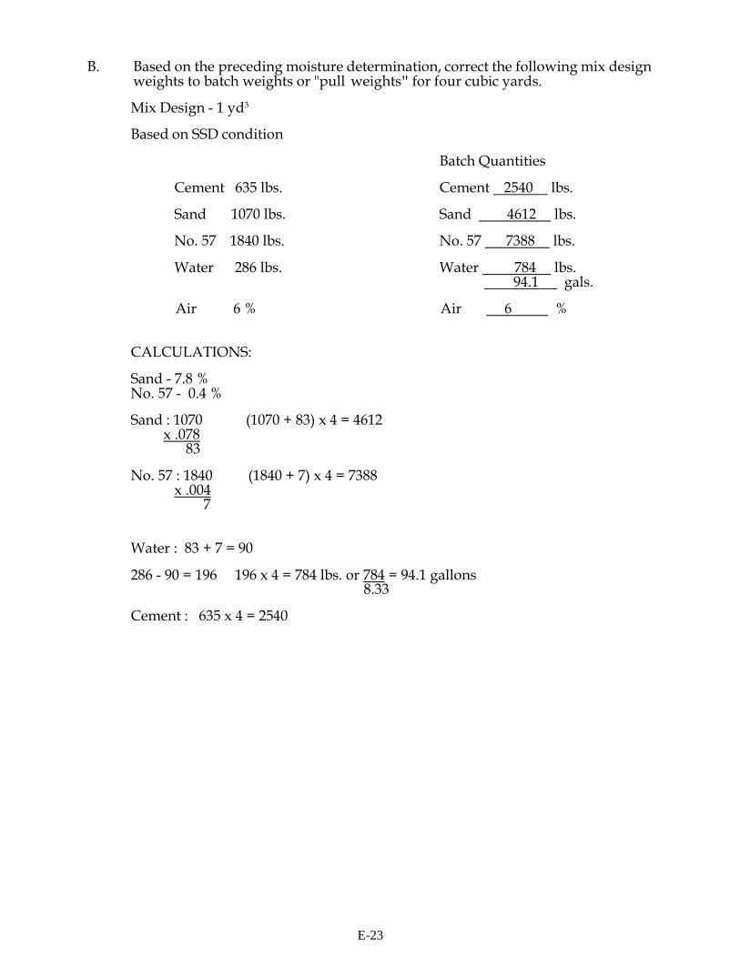
B. Based on the preceding moisture determination, correct the following mix design weights to batch weights or "pull weights" for four cubic yards.
Mix Design - 1 yd3
Based on SSD condition
Batch Quantities
Cement 635 lbs. Cement 2540 lbs.
Sand 1070 lbs. Sand 4612 lbs.
No. 57 1840 lbs. No. 57 7388 lbs.
Water 286 lbs. Water 784 lbs. 94.1 gals.
Air 6 % Air 6 %
CALCULATIONS:
Sand - 7.8 % No. 57 - 0.4 %
Sand : 1070 (1070 + 83) x 4 = 4612
x .078 83
No. 57 : 1840 (1840 + 7) x 4 = 7388
x .004 7
Water : 83 + 7 = 90
286 - 90 = 196 196 x 4 = 784 lbs. or 784 = 94.1 gallons 8.33
Cement : 635 x 4 = 2540
E-23
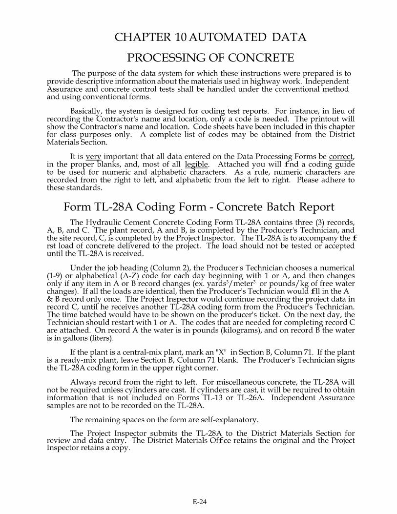
CHAPTER 10 AUTOMATED DATA
PROCESSING OF CONCRETE The purpose of the data system for which these instructions were prepared is to
provide descriptive information about the materials used in highway work. Independent Assurance and concrete control tests shall be handled under the conventional method and using conventional forms.
Basically, the system is designed for coding test reports. For instance, in lieu of
recording the Contractor's name and location, only a code is needed. The printout will show the Contractor's name and location. Code sheets have been included in this chapter for class purposes only. A complete list of codes may be obtained from the District Materials Section.
It is very important that all data entered on the Data Processing Forms be correct,
in the proper blanks, and, most of all legible. Attached you will f nd a coding guide to be used for numeric and alphabetic characters. As a rule, numeric characters are recorded from the right to left, and alphabetic from the left to right. Please adhere to these standards.
Form TL-28A Coding Form - Concrete Batch Report
The Hydraulic Cement Concrete Coding Form TL-28A contains three (3) records, A, B, and C. The plant record, A and B, is completed by the Producer's Technician, and the site record, C, is completed by the Project Inspector. The TL-28A is to accompany the f rst load of concrete delivered to the project. The load should not be tested or accepted until the TL-28A is received.
Under the job heading (Column 2), the Producer's Technician chooses a numerical
(1-9) or alphabetical (A-Z) code for each day beginning with 1 or A, and then changes only if any item in A or B record changes (ex. yards3/meter3 or pounds/kg of free water changes). If all the loads are identical, then the Producer's Technician would f ll in the A & B record only once. The Project Inspector would continue recording the project data in record C, until he receives another TL-28A coding form from the Producer's Technician. The time batched would have to be shown on the producer's ticket. On the next day, the Technician should restart with 1 or A. The codes that are needed for completing record C are attached. On record A the water is in pounds (kilograms), and on record B the water is in gallons (liters).
If the plant is a central-mix plant, mark an "X" in Section B, Column 71. If the plant
is a ready-mix plant, leave Section B, Column 71 blank. The Producer's Technician signs the TL-28A coding form in the upper right corner.
Always record from the right to left. For miscellaneous concrete, the TL-28A will
not be required unless cylinders are cast. If cylinders are cast, it will be required to obtain information that is not included on Forms TL-13 or TL-26A. Independent Assurance samples are not to be recorded on the TL-28A.
The remaining spaces on the form are self-explanatory.
The Project Inspector submits the TL-28A to the District Materials Section for
review and data entry. The District Materials Off ce retains the original and the Project Inspector retains a copy.
E-24

CODE LIST FOR CURING METHODS
CODE NO. METHOD 1 Liquid Membrane Seal 2 Polyethylene Sheeting 3 Burlap 4 Burlene 5 Wet Sand 6 Water Ponding 7 Steam 8 Heater Blanket
CODE LIST FOR TYPE OF STRUCTURE
CODE NO. TYPE STRUCTURE
1 Box Culvert and/or Appurtenances 2 Bridge (except deck) 3 Bridge Deck 4 Parapet Wall 5 Approach Slab 6 Retaining Wall 7 Curb and Gutter 8 Slope Paving 9 Ditch Paving 10 Sidewalk 11 Precast Piling 12 Precast Beams 13 Precast Miscellaneous 14 Sidewalk or Driveway 15 Miscellaneous 16 Pier Stem 17 Paving 18 Tunnel
E-25
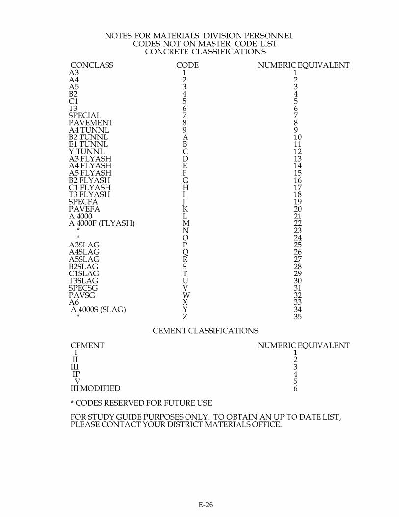
NOTES FOR MATERIALS DIVISION PERSONNEL CODES NOT ON MASTER CODE LIST
CONCRETE CLASSIFICATIONS
CONCLASS CODE NUMERIC EQUIVALENT A3 1 1 A4 2 2 A5 3 3 B2 4 4 C1 5 5 T3 6 6 SPECIAL 7 7 PAVEMENT 8 8 A4 TUNNL 9 9 B2 TUNNL A 10 E1 TUNNL B 11 Y TUNNL C 12 A3 FLYASH D 13 A4 FLYASH E 14 A5 FLYASH F 15 B2 FLYASH G 16 C1 FLYASH H 17 T3 FLYASH I 18 SPECFA J 19 PAVEFA K 20 A 4000 L 21 A 4000F (FLYASH) M 22
* N 23 * O 24
A3SLAG P 25 A4SLAG Q 26 A5SLAG R 27 B2SLAG S 28 C1SLAG T 29 T3SLAG U 30 SPECSG V 31 PAVSG W 32 A6 X 33 A 4000S (SLAG) Y 34
* Z 35
CEMENT CLASSIFICATIONS
CEMENT NUMERIC EQUIVALENT I 1 II 2 III 3 IP 4 V 5
III MODIFIED 6
* CODES RESERVED FOR FUTURE USE
FOR STUDY GUIDE PURPOSES ONLY. TO OBTAIN AN UP TO DATE LIST, PLEASE CONTACT YOUR DISTRICT MATERIALS OFFICE.
E-26
Concrete Plant Example Problem
It is the producer technician's responsibility to complete Lines A and B of the TL-28A coding form at the plant and send the form out to the state construction project site with the driver of the frst load of concrete going to the project.
Using the information below and using Mix Design No. 4-7501-07 (see next page), fll in Lines A and B (upper portion) of the TL-28A coding form.
The contractor on project 0295-127-101,C501 orders 2 cubic yards of A-3 general concrete from B. M. Jones Ready Mix Plant in Richmond (Plant Code No. 4006) on January 12, 2007.
The cement is coming from Roanoke Cement Company in Cloverdale, VA. The producer code for Bedrock S&G is 4009 and for Smith Quarries is 4015. The code for MBAE Air Entraining Agent is 02.
The free moisture on the sand is 5% and on the Coarse Aggregate (No. 57) is 0.6%.
There were 70 mixing revolutions put on the mixer at the plant and 1 gallon of water per cubic yard was withheld.
E-27
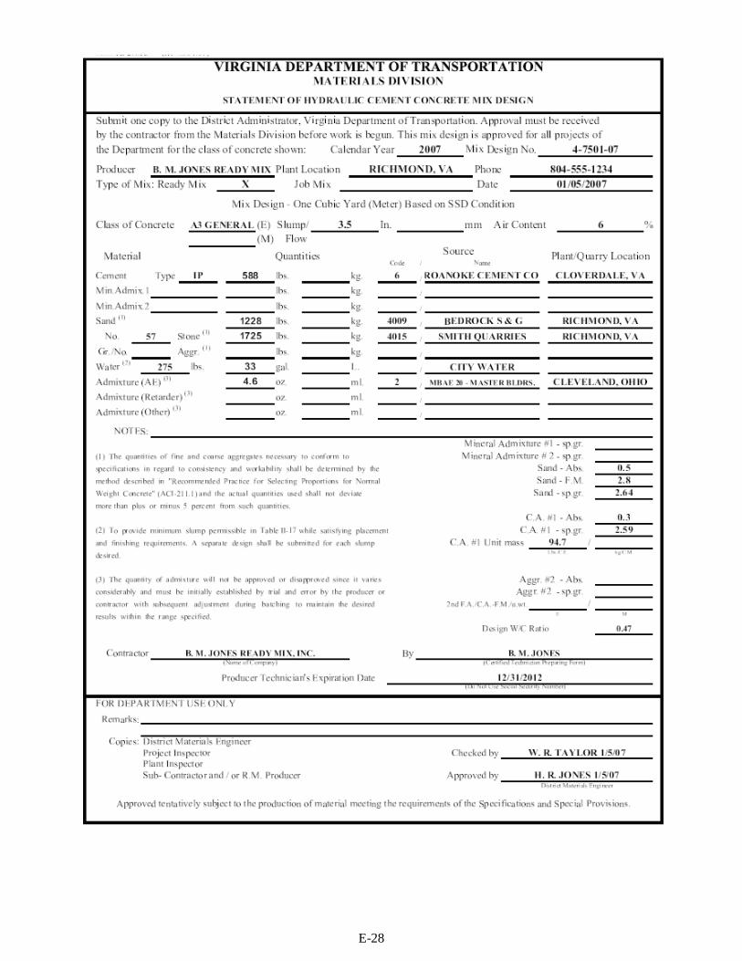
E-28
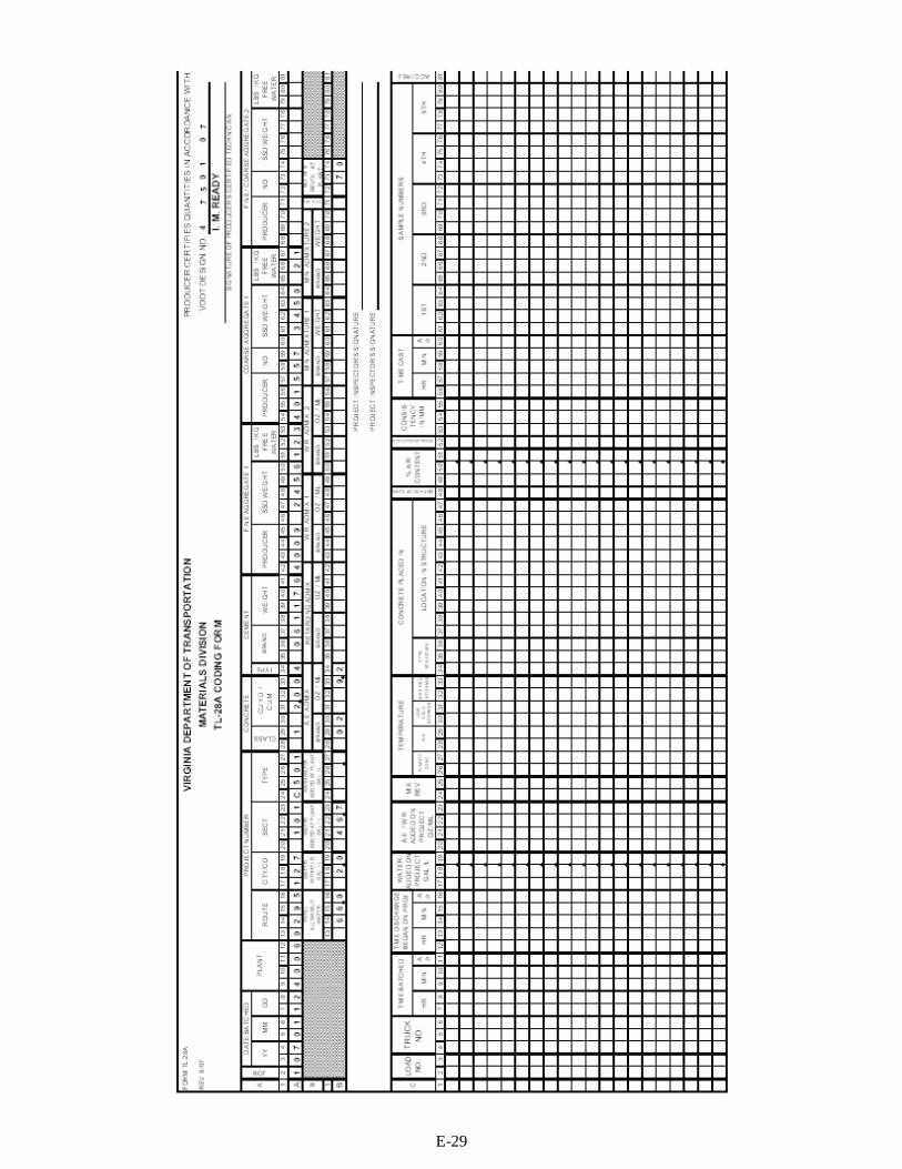
E-29

Calculations for Plant Example Problem Cement Weight Calculation - Line A 38-41 588 lbs. (From TL-27) x 2 cubic yards = 1176 lbs. of cement for 2 cubic yards
Sand, SSD Weight Calculation - Line A 46-50 1228 lbs. (From TL-27) x 2 cubic yards = 2456 lbs. of sand for 2 cubic yards
Sand, Free Water Calculation - Line A 51-53 2456 lbs. of sand (Line A 46-50) x .05 (% Free Moisture in Sand expressed as a decimal) = 122.8 (Rounded to nearest whole pound) = 123 lbs.
Coarse Aggregate (No.57), SSD Weight Calculation - Line A 60-64 1725 lbs. (From TL-27) x 2 cubic yards = 3450 lbs. of Coarse Aggregate for 2 cubic yards
Coarse Aggregate (No. 57), Free Water Calculation - Line A 65-67 3450 lbs. of C.A. (Line A 60-64) x .006 (% Free Moisture in C.A. expressed as a decimal) = 20.7 (Rounded to nearest whole pound) = 21 lbs.
Total Allowable Water - Line B 13-16 33 gals. (From TL-27) x 2 cubic yards = 66.0 gallons
Water Added at Plant - Line B 20-23 123 lbs. of free water in sand + 21 lbs. of free water in C.A. = 144 lbs. 144 lbs. of free water in sand and C.A. -; 8.33 weight of one gallon of water in lbs. = 17.3 gals. 1 gallon of water per cubic yard withheld at plant x 2 cubic yards = 2 gals. of water withheld 66.0 gallons (Line B 13-16) - 19.3 gallons of free and withheld water = 46.7 gallons of water added at plant
A. E. Admixture - Line B 31-34 4.6 oz. (TL-27) x 2 cubic yards = 9.2 oz. of Air Entrained Admixture for 2 cubic yards
E-30
Concrete Field Example Problem
Using the information below, fll in Line C (lower portion) of the TL-28A Coding Form and the Notice of Shipment of Concrete Cylinders Form TL-13.
The contractor on Project 0295-127-101,C501 has ordered 8 cubic yards of A-3 General concrete from B. M. Jones Ready Mix (Plant Code No. 4006) to be placed in a paved ditch. This is Load No. 1 batched at 2:00 p.m. on Truck No. 306.
When this load of concrete arrived on the project, the project inspector took the TL-28A from the mixer driver in order to fll out Line C on the form.
The mix was dry so the contractor told the mixer driver to add 4 gallons of water to the load and put 25 additional mixing revolutions on the drum.
The inspector took the temperature of the concrete and determined it to be 72°F. The inspector checked the slump by the slump cone method and found the slump to be 3.50 inches. The entrained air content was checked using a Type A Air Meter (Protex Air Meter) and was found to be 6.5%. This load met VDOT specifcations and was accepted. The contractor began discharge at 2:45 p.m.
The average air temperature during pouring was 75°F.
Design Quality Control Cylinders were cast by the inspector at 2:55 p.m. and were numbered 1, 1A and 1B. The cylinders were placed in a curing box for 24 hours. The low feld storage temperature was 65°F and the high feld storage temperature was 75°F.
The paved ditch was cured using polyethylene sheeting.
E-31
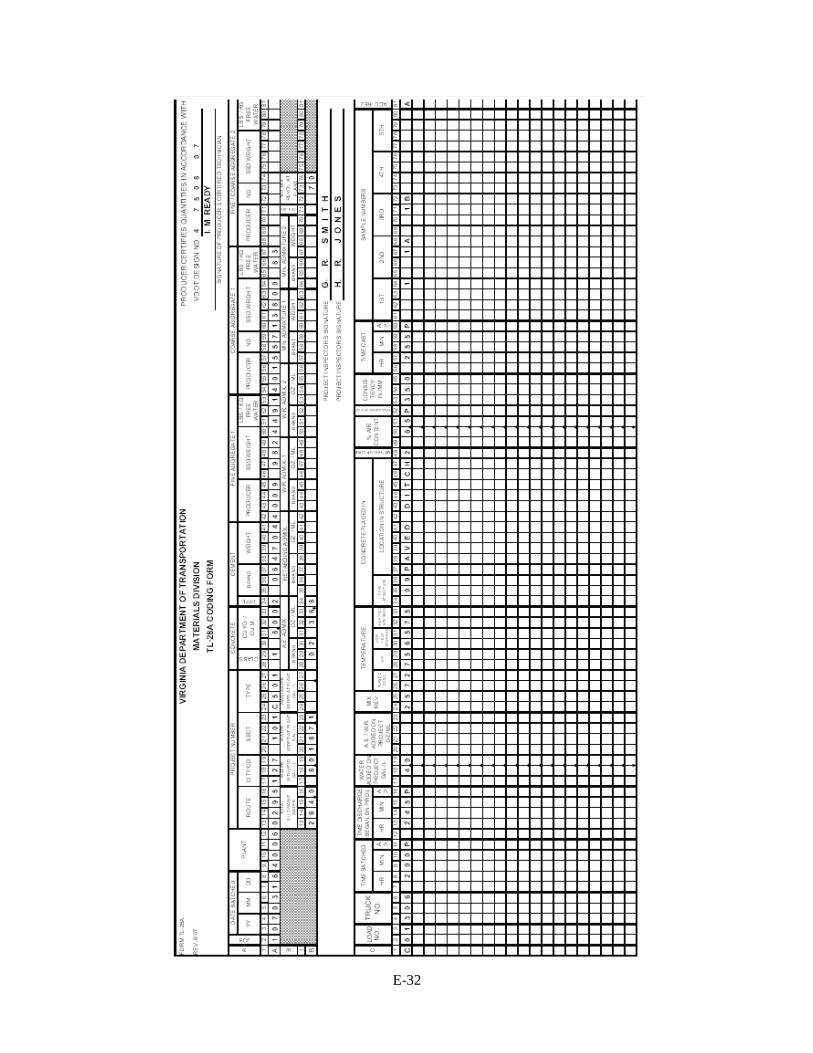
E-32

E-33
Appendix F: Prestressed HCC Quality Assurance Inspection Items
(a) Preliminary (1) Check reviewed shop drawings thoroughly to ensure that they agree with bridge
plans and special provisions. (2) Check storage of reinforcing steel, strand, and other components of prestressed
structural components, such as form void tubes, to ensure that storage is adequate to provide protection from contamination and weather.
(3) The Producer shall run levels on the prestressing bed or pallet initially and each time the pallet is removed and replaced. Also, straight edge the pallet at location which will form the bearing areas of proposed beams before each stressing operation. The QA Inspector will observe these operations periodically.
(4) See that all materials to be used in the fabrication of prestressed structural components are previously tested or certified, including gauges.
(5) Obtain Copies of mill test reports for bearing plates and other inserts. (6) See that all proposed modifications of the prestressed structural components have
been approved in writing. (b) Stressing Operation
(1) Check Producer's elongation calculation. (If calculations do not agree within 1/8 inch (3 mm), the Producer and the QA Inspector should recalculate).
(2) See that strand number and placement is correct, as well as condition (cleanliness, rust, etc.), before application of initial tension.
(3) Check the application of initial tension to ensure that the load is uniform on all strands.
(4) Check for twisted strands or strand which appears to be slack. Retension the strands which are twisted or on which the tension is doubtful.
(5) Observe the stressing operations to ensure that the elongation is applied correctly, and check the load as indicated by the gauges against elongation.
(6) Check for broken wires on strand. Allow no more than one (1) broken wire per strand. (Provided this is not more than 2% of the total number of wires).
(7) When stressing, especially draped strand, make sure that there is nothing binding the strand thereby resulting in a non-uniform stressing condition throughout the length of the bed.
(c) Forming Operation (1) Check bulkheads for proper location to obtain desired length of member and for
proper plumb, batter, skew, etc., of the ends. (2) Check placement of reinforcing steel, inserts, etc., to ensure that they are placed in
strict accordance with the bridge plans or standard. (3) Check side form and pallet for smoothness, proper fit at joints, and alignment. (4) Ensure bearing insert plates are properly positioned. (5) If form voids are used, make certain they are securely tied in place before casting
operation begins. (d) Casting Operation
(1) Observe HCC batches to ensure that uniform HCC is being obtained throughout the pour.
F-1
(2) Observe for displacement of reinforcing steel, inserts, etc., during placement and vibration of the HCC.
(3) When form voids are used, ensure they are secured to prevent floating upward or moving laterally/longitudinally during HCC placement.
(4) Observe all testing including the air content and slump tests. (e) Steaming Operation
(1) Observe preset time, the period between the completion of the pour and the introduction of the steam to the bed. Penetration Resistance test of 500 psi (3.5 MPa) may be used in lieu of preset delay period.
(2) Observe the calibration of recording thermometers periodically. (3) Make periodic checks to ensure that the temperature is uniform along the length of
the bed and to either side of the bed (4) Review curing temperature charts for rate of temperature rise, curing temperature,
and curing time to ensure that it meets the VRBS, Section 405. (f) Detensioning Operation
(1) Observe HCC cylinder compressive strength test for detensioning on a random basis.
(2) Observe detensioning procedures periodically to ensure that these meet the VRBS, Section 405.
(g) Storage and Handling (1) Observe the operation of lifting and transporting the prestressed structural
components from the beds to the storage area, and to barge or truck. (2) Visit the storage area periodically to observe the condition of the prestressed
structural components and their supports. (h) Shipping
(1) Check and record length, camber, and horizontal alignment of the beams prior to shipping.
(2) Ensure that the required design compressive strengths have been met. (3) Check the support point for prestressed structural components on the barge or truck. (4) Record identification number of member and stamp the member with the QA
Inspection seal.
F-2