chapter 5civilwares.free.fr/geotechnical engineering - principles and... · chapter 5 effective...
TRANSCRIPT

CHAPTER 5EFFECTIVE STRESS AND PORE WATERPRESSURE
5.1 INTRODUCTIONThe pressure transmitted through grain to grain at the contact points through a soil mass istermed as intergranular or effective pressure. It is known as effective pressure since this pressureis responsible for the decrease in the void ratio or increase in the frictional resistance of a soilmass.
If the pores of a soil mass are filled with water and if a pressure induced into the pore water,tries to separate the grains, this pressure is termed as pore water pressure or neutral stress. Theeffect of this pressure is to increase the volume or decrease the frictional resistance of the soil mass.
The effects of the intergranular and pore water pressures on a soil mass can be illustrated bymeans of simple practical examples.
Consider a rigid cylindrical mold, Fig. 5.1(a), in which dry sand is placed. Assume that thereis no side friction. Load Q is applied at the surface of the soil through a piston. The load applied atthe surface is transferred to the soil grains in the mold through their points of contact. If the load isquite considerable, it would result in the compression of the soil mass in the mold. The compressionmight be partly due to the elastic compression of the grains at their points of contact and partly dueto relative sliding between particles. If the sectional area of the cylinder is A, the average stress atany level XY may be written as
-«=f (5.1)
The stress aa is the average stress and not the actual stress prevailing at the grain to graincontacts which is generally very high. Any plane such as XY will not pass through all the points ofcontact and many of the grains are cut by the plane as shown in Fig. 5.1(b). The actual points of
143

144 Chapter 5
contact exhibit a wavy form. However, for all practical purposes the average stress is considered.Since this stress is responsible for the deformation of the soil mass, it is termed the intergranular oreffective stress. We may therefore write,
a = (5.2)
where cr'is the effective stress.Consider now another experiment. Let the soil in the mold be fully saturated and made
completely watertight. If the same load Q is placed on the piston, this load will not be transmitted tothe soil grains as in the earlier case. If we assume that water is incompressible, the external load Qwill be transmitted to the water in the pores. This pressure that is developed in the water is called thepore water or neutral stress uw as shown schematically in Fig. 5.1(c). This pore water pressure uw
prevents the compression of the soil mass. The value of this pressure is
GA
(5.3)
If the valve V provided in the piston is opened, immediately there will be expulsion of waterthrough the hole in the piston. The flow of water continues for some time and then stops.
The expulsion of water from the pores decreases the pore water pressure and correspondinglyincreases the intergranular pressure. At any stage the total pressure Q/A is divided between waterand the points of contact of grains. A new equation may therefore be written as
Total pressure cr[ - — = Intergranular pressure + pore water pressureA
Piston
Rigid cylindricalmold
(a) Soil under load in a rigid container
(b) Intergranular pressure (c) Porewater pressure,
Figure 5.1 Effective and pore water pressures

Effective Stress and Pore Water Pressure 145
or at =<?'+uw (5.4)
Final equilibrium will be reached when there is no expulsion of water. At this stage the porewater pressure uw = 0. All the pressure will be carried by the soil grains. Therefore, we can write,
at = <r' (5.5)
The pore water pressure uw can be induced in the pores of a soil mass by a head of water overit. When there is no flow of water through the pores of the mass, the intergranular pressure remainsconstant at any level. But if there is flow, the intergranular pressure increases or decreasesaccording to the direction of flow. In partially saturated soils part of the void space is occupied bywater and part by air. The pore water pressure uw must always be less than the pore air pressure (ua).Bishop (1955) proposed an equation for computing the effective pressure in partially saturatedsoils. This equation contains a parameter which cannot be determined easily. Since this equation isonly of academic interest, no further discussion is necessary here.
5.2 STRESSES WHEN NO FLOW TAKES PLACE THROUGH THESATURATED SOIL MASSIn Fig. 5.2 the container A is filled with sand to a depth zl and water to a depth z2 above the sandsurface. A flexible tube connects the bottom of the container A to another container B. The waterlevels are kept constant in these two containers.
The water surfaces in both the containers in Fig. 5.2(a) are kept at the same level. Under thiscondition, no flow takes place from one container to another.
Consider two points M and N as shown in the figure on a horizontal plane. The water pressureat M should be equal to the pressure at N according to the laws of hydraulics. Therefore,
the water pressure at N=UZ = (Z +z2)Yw (5-6)
The pressure uz is termed as the pore water pressure acting on the grains at depth z from thesurface of the sample. However, the total pressure at point N is due to the water head plus the weightof the submerged soil above N. If yb is the submerged unit weight of the soil, the total pressure at N is
az = zyb+(z + z2)yw (5.7)
The intergranular or effective pressure at the point N is the difference between the total andthe pore water pressures. Therefore, the effective pressure CF,' is
<rz=<rz-uz=zrb+(z + z2)rw-(z + z2')rw=zrb (5.8a)
Equation (5.8a) clearly demonstrates that the effective pressure cr,' is independent of thedepth of water z2 above the submerged soil surface. The total pore water and effective pressures atthe bottom of the soil sample are as follows
Total pressure crt = ac = (z, + Z2)YW + z\Yb (5.8b)
Pore water pressure uc = (zi +Z2)yw (5.8c)
Effective pressure a'c - (oc ~uc} = z\Yb (5.8d)
The stress diagrams are shown in Fig. 5.2(b).

146 Chapter 5
Total
M
fz
L N<•!
Stress diagrams
Pore water
o
Effective
o o'
(a) (b)
Figure 5.2 Stresses when no flow takes place
5.3 STRESSES WHEN FLOW TAKES PLACE THROUGH THE SOILFROM TOP TO BOTTOMIn Fig. 5.3(a) the water surface in container B is kept at h units below the surface in A. Thisdifference in head permits water to flow from container A to B.
Since container B with the flexible tube can be considered as a piezometer tube freelycommunicating with the bottom of container A, the piezometric head or the pore water pressurehead at the bottom of container A is (z, + z2 - h). Therefore, the pore water pressure uc at the bottomlevel is
u = (5.9)
As per Fig. 5.3(a), the pore water pressure at the bottom of container A when no flow takesplace through the soil sample is
« = (5.10)
It is clear from Eq. (5.9) and (5.10) that there is a decrease in pore water pressure to the extentof hy when water flows through the soil sample from top to bottom. It may be understood that thisdecrease in pore water pressure is not due to velocity of the flowing water. The value of the velocityhead V2/2g is a negligible quantity even if we take the highest velocity of flow that is encounteredin natural soil deposits. As in Fig. 5.2(a), the total pressure oc at the bottom of the container in thiscase also remains the same. Therefore,
The effective pressure <JC' at the bottom of the container is
- u
(5.11)
(5.12)
Equation (5.12) indicates that in this case there is an increase in the effective pressure byhy at the bottom of the container A as compared to the earlier case. The effective pressure at thetop surface of the sample is zero as before. Therefore, the effective pressure cr./ at any depth z canbe written as

Effective Stress and Pore Water Pressure 147
r\
\
•ITotal
Stress diagrams
Pore water Effectivea'
(a) (b)
Figure 5.3 Stresses when flow takes place from top to bottom
Z\(5.13)
Equation (5.13) indicates that hzYjz{ is the increase in the effective pressure as the waterflows from the surface to a depth z. This increase in effective pressure due to the flow of waterthrough the pores of the soil is known as seepage pressure. It may be noted that h is the total lossof head as the water flows from the top surface of the sample to a depth zr
The corresponding loss of head at depth z is (z/z^h. Since (/z/Zj) = /, the hydraulic gradient,the loss of head at depth z can be expressed as iz. Therefore the seepage pressure at any depth maybe expressed as izyw- The effective pressure at depth z can be written as
<r'z=zrb+izrw (5.14)'
The distribution of pore water and effective pressures are shown in Fig. 5.3(b). In normal soildeposits when flow takes place in the direction of gravity there will be an increase in the effectivepressure.
5.4 STRESSES WHEN FLOW TAKES PLACE THROUGH THE SOILFROM BOTTOM TO TOPIn Fig. 5.4(a), the water surface in container B is kept above that of A by h units. This arrangementpermits water to flow upwards through the sample in container A. The total piezometric or the porewater head at the bottom of the sample is given by
(z 1 +z 2 +/z )
Therefore, the pore water pressure uc at the bottom of the sample is
(5.15)
As before the total pressure head o~c at the bottom of the sample is
(5.16)

148 Chapter 5
Stress diagrams
\ I Total Effective
z/b ~ *zy»
(a) (b)
Figure 5.4 Stresses when flow takes place from bottom to top
The effective pressure o~c' at the bottom of sample is, therefore,
= °c ~uc = hy
As in Eq. (5.14) the effective pressure at any depth z can be written as
(5.17)
(5.18)
Equation (5.18) indicates that there is a decrease in the effective pressure due to upwardflow of water. At any depth z, zyb is the pressure of the submerged soil acting downward and izyb
is the seepage pressure acting upward. The effective pressure o~' reduces to zero when these twopressures balance. This happens when
' = zyb - izy = 0 or / = / = • (5.19)
Equation (5.19) indicates that the effective pressure reduces to zero when the hydraulicgradient attains a maximum value which is equal to the ratio of the submerged unit weight of soiland the unit weight of water. This gradient is known as the critical hydraulic gradient ic. In suchcases, cohesionless soils lose all of their shear strength and bearing capacity and a visible agitationof soil grains is observed. This phenomenon is known as boiling or a quick sand condition. Bysubstituting in Eq. (5.19) for yb
yI -i)'
l + ewe have
G -1(5.20)
The critical gradient of natural granular soil deposits can be calculated if the void ratios of thedeposits are known. For all practical purposes the specific gravity of granular materials can beassumed as equal to 2.65. Table 5.1 gives the critical gradients of granular soils at different voidratios ranging from 0.5 to 1.0.

Effective Stress and Pore Water Pressure 149
Table 5.1 Critical hydraulic gradients of granular soils
Soil No. Void ratio ic
1 0.5 1.10
2 0.6 1.03
3 0.7 0.97
4 0.8 0.92
5 1.0 0.83
It can be seen from Table 5.1 that the critical gradient decreases from 1.10 by about 25percent only as the void ratio increases by 100 percent from an initial value of 0.5 to 1.0. The voidratio of granular deposits generally lies within the range of 0.6 to 0.7 and as such a critical gradientof unity can justifiably be assumed for all practical purposes. It should be remembered that a quickcondition does not occur in clay deposits since the cohesive forces between the grains prevent thesoil from boiling.
Quick conditions are common in excavations below the ground water table. This can beprevented by lowering the ground water elevation by pumping before excavation. Quick conditionsoccur most often in fine sands or silts and cannot occur in coarse soils. The larger the particle size, thegreater is the porosity. To maintain a critical gradient of unity, the velocity at which water must besupplied at the point of inflow varies as the permeability. Therefore a quick condition cannot occur ina coarse soil unless a large quantity of water can be supplied.
5.5 EFFECTIVE PRESSURE DUE TO CAPILLARY WATER RISE IN SOIL
The term water level, water table and phreatic surface designate the locus of the levels to whichwater rises in observation wells in free communication with the voids of the soil at a site. The watertable can also be defined as the surface at which the neutral stress uw in the soil is equal to zero.
If the water contained in the soil were subjected to no force other than gravity, the soil abovethe water table would be perfectly dry. In reality, every soil in the field is completely saturatedabove this level up to a certain height. The water that occupies the voids of the soil located abovethe water table constitutes soil moisture.
If the lower part of the mass of dry soil comes into contact with water, the water rises inthe voids to a certain height above the free water surface. The upward flow into the voids of thesoil is attributed to the surface tension of the water. The height to which water rises above thewater table against the force of gravity is called capillary rise. The height of capillary rise isgreatest for very fine grained soil materials. The water that rises above the water table attainsthe maximum height hc only in the smaller voids. A few large voids may effectively stopcapillary rise in certain parts of the soil mass. As a consequence, only a portion of the capillaryzone above the free water surface remains fully saturated and the remainder is partiallysaturated.
The seat of the surface tension is located at the boundary between air and water. Within theboundary zone the water is in a state of tension comparable to that in a stretched rubber membraneattached to the walls of the voids of a soil. However, in contrast to the tension in a stretchedmembrane, the surface tension in the boundary film of water is entirely unaffected by either thecontraction or stretching of the film. The water held in the pores of soil above the free water surfaceis retained in a state of reduced pressure. This reduced pressure is called capillary pressure or soilmoisture suction pressure.
The existence of surface tension can be demonstrated as follows:

150 Chapter 5
2 TeL cos a
Figure 5.5 Needle smeared with grease floating on water
A greased sewing needle, Fig. 5.5, can be made to float on water because water has noaffinity to grease, and, therefore, the water surface curves down under the needle until the upwardcomponent of the surface tension is large enough to support the weight of the needle. In Fig. 5.5,7^ is the surface tension per unit length of the needle and Wn the weight of the needle. The upwardvertical force due to surface tension is 2TL cos a, where L is the length of the needle. The needlefloats when this vertical force is greater than the weight of the needle Wn acting downwards.
Rise of Water in Capillary TubesThe phenomenon of capillary rise can be demonstrated by immersing the lower end of a very smalldiameter glass tube into water. Such a tube is known as capillary tube. As soon as the lower end ofthe tube comes into contact with water, the attraction between the glass and the water moleculescombined with the surface tension of the water pulls the water up into the tube to a height hc above thewater level as shown in Fig. 5.6(a). The height hc is known as the height of capillary rise. The uppersurface of water assumes the shape of a cup, called the 'meniscus' that joins the walls of the tube at anangle a known as the contact angle.
On the other hand, if the tube is dipped into mercury a depression of the surface develops inthe tube below the surface of the mercury, with the formation of a convex meniscus as shown inFig. 5.6(b). The reason for the difference between the behavior of water and mercury resides in thedifferent affinity between the molecules of the solid and water or mercury. If there is a strongaffinity between the molecules of the solid and the liquid, the surface of the liquid will climb up onthe wall of the solid until a definite contact angle a is established. The contact angle between aclean moist glass surface and water is zero, that is, the water surface touches the glass surfacetangentially. For the case of a dry glass surface and water, a is not a constant. It may be as high as45° at first then gradually reducing to much smaller values. Probably the inevitable contaminationof surfaces cleaned by ordinary methods, and the humidity of air are responsible for suchvariations. Fig. 5.6(c) shows the contact angles between water and the surfaces under differentconditions.
Surface Tension
Surface tension is a force that exists at the surface of the meniscus. Along the line of contact betweenthe meniscus in a tube and the walls of the tube itself, the surface tension, Ts, is expressed as the forceper unit length acting in the direction of the tangent as shown in Fig. 5.7(a). The components of thisforce along the wall and perpendicular to the wall are
Along the wall = T cos a per unit length of wall

Effective Stress and Pore Water Pressure 151
Water
(a)
MeniscusT,
Glass tube
Meniscus
Glass tube
Convex meniscus
\ Mercury
(b)
a = 0 0 < a < 45° a > 90°Moist glass Dry glass Greasy glass
surface surface surface
(c)
Figure 5.6 Capillary rise and meniscus
Normal to the wall = Ts sin a per unit length of wall.
The force normal to the wall tries to pull the walls of the tube together and the one along the wallproduces a compressive force in the tube below the line of contact.
The meniscus can be visualized as a suspension bridge in three dimensions which issupported on the walls of the tube. The column of water of height hc below the meniscus issuspended from this bridge by means of the molecular attraction of the water molecules. If themeniscus has stopped moving upward in the tube, then there must be equilibrium between theweight of the column of water suspended from the meniscus and the force with which the meniscusis clinging to the wall of the tube. We can write the following equation of equilibrium
TidT cos« = or h =4T cos a
(5.21)
The surface tension Ts for water at 20 °C can be taken as equal to 75 x 10~8 kN per cm. Thesurface tensions of some of the common liquids are given in Table 5.2.
Equation (5.21) can be simplified by assuming a = 0 for moist glass and by substituting for Ts.Therefore, for the case of water, the capillary height hc can be written as
h =47" 4x75xlO- 8 xl0 6 03
ddyw dx9.Sl
In Eq. (5.22) h and d are expressed in cm, and, v = 9.81 kN/m3.
(5.22)

152 Chapter 5
Table 5.2 Surface tension of some liquids at 20 °C
Liquids 7" kN/cm x 1CT8
Ethyl AlcoholBenzeneCarbon Tetra ChlorideMercuryPetroleumWater
22.0328.9026.80
573.0026.0075.00
Stress Distribution in Water Below the Meniscus
Figure 5.7(b) shows a capillary tube with its bottom end immersed in water. The pressure isatmospheric at points A and B. Since point C is at the same level as A, according to the laws ofhydraulics, the pressure at C is also atmospheric. Since the point D which is just below the meniscusis higher than point C by the head hc, the pressure at D must be less than atmospheric by the amounthcyw. Therefore, the pressure at any point in water between C and D is less than atmospheric. Thatmeans, the water above point C is in tension if we refer to atmospheric pressure as zero pressure.The tension in water at any height h above C is given by hyw. By contrast, the pressure in the waterbelow the free surface A is above atmospheric and therefore is in compression. The stressdistribution in water is given in Fig. 5.7(b).
Tr sin a -*-a
Water
-*- Ts sin aa
- Glass tube
(a) Forces due to surface tension
Tension
Stressdistribution
\
(b)
uc = 4 Tsld
Water \ Capillary tube wallunder compression
(c)
Figure 5.7 Capillary pressure

Effective Stress and Pore Water Pressure
Thus the tension uw in water immediately below the meniscus is given by
47 cos a
153
(5.23)
If rm is the radius of the meniscus, Fig. 5.7(a), we can write,
dr = or d = 2r cos am 2cosa
Substituting for d in Eq. (5.23), we have
u = —4Ts cos a
2r cos a
2Ts
r (5.24)
It may be noted here that at the level of the meniscus the magnitude of the capillary pressureu that compresses the wall of the tube is also equal to the capillary tension in the water just belowthe meniscus. The magnitude of the capillary pressure uc remains constant with depth as shown inFig. 5.7(c) whereas the capillary tension, uw, in water varies from a maximum of hcYw at themeniscus level to zero at the free water surface level as shown in Fig. 5.7(b).
Capillary Rise of Water in Soils
In contrast to capillary tubes the continuous voids in soils have a variable width. They communicatewith each other in all directions and constitute an intricate network of voids. When water rises intothe network from below, the lower part of the network becomes completely saturated. In the upperpart, however, the water occupies only the narrowest voids and the wider areas remain filled withair.
Fig. 5.8(a) shows a glass tube filled with fine sand. Sand would remain fully saturated only upto a height h' which is considerably smaller than hc. A few large voids may effectively stopcapillary rise in certain parts. The water would rise, therefore, to a height of hc only in the smallervoids. The zone between the depths (hc - h'J will remain partially saturated.
Soilsample s
V
~
**,"/:•• :-v
ft
•V°-j :!••'£
/1r
h
cm)ry zone ff 150T
CM
Tew
Partially -g 100hc - h'c saturated &
zone =3c , '§,
?? sn<+-
, , Saturated 2"c £i zone OBi 3
y
/)A/ ^"10 1.0 0.1 0.01 0.001
Grain size (mm) log scale
(a) Height of capillary rise (b) Rate of capillary rise in soil consisting ofuniform quartz powder
Figure 5.8 Capillary rise in soils

154 Chapters
Capillary rise of water
/~z£r\_ T,
////////SS/////S/S/////////////////////////S//7///////S/7////S//S/7/S//S
Figure 5.9 Capillary siphoning
The height of the capillary rise is greatest for very fine grained soils materials, but the rateof rise in such materials is slow because of their low permeability. Fig. 5.8(b) shows therelationship between the height of capillary rise in 24 hours and the grain size of a uniform quartzpowder. This clearly shows that the rise is a maximum for materials falling in the category of siltsand fine sands.
As the effective grain size decreases, the size of the voids also decreases, and the height ofcapillary rise increases. A rough estimation of the height of capillary rise can be determined fromthe equation,
Ch^^D~ (5'25)
eLJ\Q
in which e is the void ratio, DIQ is Hazen's effective diameter in centimeters, and C is an empiricalconstant which can have a value between 0.1 and 0.5 sq. cm.
Capillary SiphoningCapillary forces are able to raise water against the force of gravity not only into capillary tubes orthe voids in columns of dry soil, but also into narrow open channels or V-shaped grooves. If thehighest point of the groove is located below the level to which the surface tension can lift the water,the capillary forces will pull the water into the descending part of the groove and will slowly emptythe vessel. This process is known as capillary siphoning. The same process may also occur in thevoids of soil. For example, water may flow over the crest of an impermeable core in a dam in spiteof the fact that the elevation of the free water surface is below the crest of the core as shown inFig. 5.9.
Capillary Pressure in Soils
The tension uw in water just below the meniscus is given by Eq. (5.23) as
4T costf
Since this pressure is below atmospheric pressure, it draws the grains of soils closer to eachother at all points where the menisci touch the soil grains. Intergranular pressure of this type iscalled capillary pressure. The effective or intergranular pressure at any point in a soil mass can beexpressed by
of = a-u, (5.26)

Effective Stress and Pore Water Pressure
Capillary fringe
155
(b) (c) (d) (e)
Figure 5.10 Effect of capillary pressure uc on soil vertical stress diagram
where ot is the total pressure, tf is the effective or the intergranular pressure and uw is the porewater pressure. When the water is in compression uw is positive, and when it is in tension uw isnegative. Since uw is negative in the capillary zone, the intergranular pressure is increased by uw.The equation, therefore, can be written as
of = at-(-uw) = at + uw (5.27)
The increase in the intergranular pressure due to capillary pressure acting on the grainsleads to greater strength of the soil mass.
Stress Condition in Soil due to Surface Tension Forces
It is to be assumed here that the soil above the ground water table remains dry prior to the rise ofcapillary water. The stress condition in the dry soil mass changes due to the rise of capillary water.
Now consider the soil profile given in Fig. 5.10(a). When a dry soil mass above the GWTcomes in contact with water, water rises by capillary action. Let the height of rise be hc and assumethat the soil within this zone becomes saturated due to capillary water. Assume that the menisciformed at height hc coincide with the ground surface. The plane of the menisci is called thecapillary fringe.
The vertical stress distribution of the dry soil mass is shown in Fig 5.10(b). The vertical stressdistribution of the saturated mass of soil is given in Fig 5.10(d). The tension in the water ismaximum at the menisci level, say equal to uw and zero at the GWT level as shown in Fig. 5.10(e).
Prior to capillary rise the maximum pressure of the dry mass, rfd, at the GWT level is
where, yd = dry unit weight of soil.After the capillary rise, the maximum pressure of the saturated weight of soil at the GWT
level is
Since the pore water pressure at the GWT level is zero, it is obvious that the differencebetween the two pressures o/
sat and tf d represents the increase in pressure due to capillary risewhich is actually the capillary pressure, which may be expressed as
Mr ~~ i-Wsat ~~ I A) (.3.)

156 Chapter 5
By substituting for
^, andl + e
in Eq. (a), we have, after simplifying
l + e ct (5.28)
where, e = void ratio,n = porosity
It is clear from Eq. (5.28) that the capillary pressure for soil is directly proportional to theporosity of the soil and this pressure is very much less than h./ which is used only for a fine boreand uniform diameter capillary tube.
The distribution of capillary pressure uc (constant with depth) is given in Fig. 5.10(c). Thefollowing equation for the pressure at any depth z may be written as per Fig. 5.10
(5.29)
Example 5.1
The depth of water in a well is 3 m. Below the bottom of the well lies a layer of sand 5 meters thickoverlying a clay deposit. The specific gravity of the solids of sand and clay are respectively 2.64and 2.70. Their water contents are respectively 25 and 20 percent. Compute the total, intergranularand pore water pressures at points A and B shown in Fig. Ex. 5.1.
Solution
The formula for the submerged unit weight is
l + e
Since the soil is saturated,
3m
5 m2m
2 m
Sand
Clay
Figure Ex. 5.1

Effective Stress and Pore Water Pressure 157
_ . 9.81(2.64-1) 3For sand, y, = = 9.7 kN/mJ
* 1 + 0.25x2.64
For clay, y, = 9'81(2JO " ̂ = 10.83 kN/m3
* 1 + 0.20x2.70
Pressure at point A
(i) Total pressure = 3 x 9.7 (sand) + 6 x 9.81 = 29.1 + 58.9 = 88 kN/m2
(ii) Effective pressure = 3 x 9.7 = 29.1 kN/m2
(iii) Pore water pressure = 6 x 9.81 = 58.9 kN/m2
Pressure at point B
(i) Total pressure = 5 x 9.7 + 2 x 10.83 + 10 x 9.81 = 168.3 kN/m2
(ii) Intergranular pressure = 5 x 9.7 + 2 x 10.83 = 70.2 kN/m2
(iii) Pore water pressure =10x9.81=98.1 kN/m2
Example 5.2If water in the well in example 5.1 is pumped out up to the bottom of the well, estimate the changein the pressures at points A and B given in Fig. Ex. 5.1.
SolutionChange in pressure at points A and B
(i) Change in total pressure = decrease in water pressure due to pumping
= 3x9.81=29.43 kN/m2
(ii) Change in effective pressure = 0
(iii) Change in pore water pressure = decrease in water pressure due to pumping
= 3x9.81=29.43 kN/m2
Example 5.3A trench is excavated in fine sand for a building foundation, up to a depth of 13 ft. The excavationwas carried out by providing the necessary side supports for pumping water. The water levels at thesides and the bottom of the trench are as given Fig. Ex. 5.3. Examine whether the bottom of thetrench is subjected to a quick condition if Gs = 2.64 and e = 0.7. If so, what is the remedy?
SolutionAs per Fig. Ex. 5.3 the depth of the water table above the bottom of the trench = 10 ft. The sheetingis taken 6.5 ft below the bottom of the trench to increase the seepage path.
G -1The equation for the critical gradient is / =
l + e
If the trench is to be stable, the hydraulic gradient, /, prevailing at the bottom should be lessthan i . The hydraulic gradient i is

158 Chapter 5
//A\V/A\\3f t
//A\V/A\\
10ft
6.5ft
_LFigure Ex. 5.3
There will be no quick condition if,
L l + e
From the given data
2.64-1 = 1.641 + 0.7 1.7
* = - * = , .54L 6.5
It is obvious that h/L > ic. There will be quick condition.
Remedy:(i) Increase L to at least a 13 ft depth below the bottom of trench so that h/L = 0.77 which
gives a margin of factor of safety.or (ii) Keep the water table outside the trench at a low level by pumping out water. This reduces
the head h.or (iii) Do not pump water up to the bottom level of the trench. Arrange the work in such a way
that the work may be carried out with some water in the trench.Any suggestion given above should be considered by keeping in view the site conditionsand other practical considerations.
Example 5.4A clay layer 3.66 m thick rests beneath a deposit of submerged sand 7.92 m thick. The top of thesand is located 3.05 m below the surface of a lake. The saturated unit weight of the sand is 19.62kN/m3 and of the clay is 18.36 kN/m3.
Compute (a) the total vertical pressure, (b) the pore water pressure, and (c) the effectivevertical pressure at mid height of the clay layer (Refer to Fig. Ex. 5.4).
Solution(a) Total pressure
The total pressure cr, over the midpoint of the clay is due to the saturated weights of clay andsand layers plus the weight of water over the bed of sand, that is
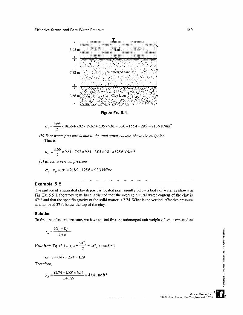
Effective Stress and Pore Water Pressure 159
T '3.05m Lake
/psxXK^v&tfSS^^
7.92m. ' • ' • • ' • ' • .' '••':••':''•. Submerged sand :: ' . . . ' • • ' [ • ' • ' . ' / •
3.66m'I !'6--''v'f' '/•'••?. J'''--/*'.'"'•}.•••'•'.•• '•£•'•: .v:'-;:'*'.'''*Vj'l' :C *•••
_I_ '• '•'•:-'-'- '* ••"''••''-."•..* ••' ';'•":•. "v •."-'•.•'•."•..' ••' ':'•":•. •* •; '•..'•
cr, =3.66
Figure Ex. 5.4
x 18.36 +7.92 x 19.62 + 3.05 x 9.81 = 33.6 + 155.4 + 29.9 = 218.9 kN/m2
(b) Pore water pressure is due to the total water column above the midpoint.That is
3.66u.. = x 9.81 + 7.92 x 9.81 + 3.05 x 9.81 = 125.6 kN/m2
(c) Effective vertical pressure
a-u = &' = 218.9-125.6 = 93.3 kN/m2
Example 5.5The surface of a saturated clay deposit is located permanently below a body of water as shown inFig. Ex. 5.5. Laboratory tests have indicated that the average natural water content of the clay is41% and that the specific gravity of the solid matter is 2.74. What is the vertical effective pressureat a depth of 37 ft below the top of the clay.
Solution
To find the effective pressure, we have to find first the submerged unit weight of soil expressed as
Yh =l + e
wG,Now from Eq. (3.14a), e = *- = wGs since 5 = 1
or e = 0.47 x 2.74 = 1.29
Therefore,
(2.74-1.00)x62.4=47411b/ft3
* 1 + 1.29

160 Chapter 5
Lake
/A\VA\VA\VA\\//>, \VA\VA\VA\\
Clay deposit
37ft
D
/A\VA\\
A\VA\VA\VW\\
Figure Ex. 5.5
Effective pressure, a' = 37 x 47.41 = 1754 lb/ft:
Example 5.6If the water level in Ex. 5.5 remains unchanged and an excavation is made by dredging, what depthof clay must be removed to reduce the effective pressure at point A at a depth of 37 ft by 1000 lb/ft2?(Fig. Ex. 5.5)
Solution
As in Ex. 5.5, yb = 47.41 lb/ft3, let the depth of excavation be D. The effective depth over the pointA is (37 - D) ft. The depth of D must be such which gives an effective pressure of(1754 - 1000) lb/ft3 = 754 lb/ft2
or (37 -D)x 47.41 =754
^ 37x47.41-754 _ 1 i ror D = = 21.1 ft47.41
Example 5.7The water table is lowered from a depth of 10 ft to a depth of 20 ft in a deposit of silt. All the silt issaturated even after the water table is lowered. Its water content is 26%. Estimate the increase in theeffective pressure at a depth of 34 ft on account of lowering the water table. Assume Gs = 2.7.
Solution
Effective pressure before lowering the water table.The water table is at a depth of 10 ft and the soil above this depth remains saturated but not
submerged. The soil from 10 ft to 20 ft remains submerged. Therefore, the effective pressure at34 ft depth is
(34-10)^

Effective Stress and Pore Water Pressure 161
,
v"^
34
-
20
ft
11
10ftft
i .<
10ft[ ISilt deposit
Oric
>
Figure Ex. 5.7
Now Y = ——' Ysat l + e ' '° l + e
Therefore, e = 0.26 x 2.7 = 0.70
62.4(2.7.0.7)sat 1 + 0.7
62.4(2.7-1)
-, yw = 62.4 lb/ft3, e = wGs for S = 1
1 + 0.7
(j{ = 10 x 124.8 + 24 x 62.4 = 2745.6 lb/ft2
Effective pressure after lowering of water tableAfter lowering the water table to a depth of 20 ft, the soil above this level remains saturated
but effective and below this submerged. Therefore, the altered effective pressure is
a'i = 20^sat + (34 ~ 2°)^fc = 20 x 124-8 +14 x 62-4 = 3369-6 lb/ft2
The increase in the effective pressure is
cr'2 - CT{ = ACT' = 3369.6 - 2745.6 = 624.0 lb/ft2
Example 5.8Compute the critical hydraulic gradients for the following materials: (a) Coarse gravel,k = 10 cm/sec, Gs = 2.67, e = 0.65 (b) sandy silt, k = IQr* cm/sec, G5 = 2.67, e = 0.80
Solution
As per Eq. (5.20), the critical gradient ic may be expressed as
G -1
l + e

162
(a) Coarse gravel
Chapter 5
c 1 + 0.65
(b) Sandy silt
1 + 0.80
Example 5.9A large excavation is made in a stiff clay whose saturated unit weight is 109.8 lb/ft3. When thedepth of excavation reaches 24.6 ft, cracks appear and water begins to flow upward to bring sand tothe surface. Subsequent borings indicate that the clay is underlain by sand at a depth of 36.1 ftbelow the original ground surface.
What is the depth of the water table outside the excavation below the original ground level?
SolutionMaking an excavation in the clay creates a hydraulic gradient between the top of the sand layer andthe bottom of the excavation. As a consequence, water starts seeping in an upward direction fromthe sand layer towards the excavated floor. Because the clay has a very low permeability, flowequilibrium can only be reached after a long period of time. The solution must be considered overa short time interval.
The floor of the excavation at depth d is stable only if the water pressure <Jw at the top of thesand layer at a depth of 36.1 ft is counterbalanced by the saturated weight <7, per unit area of theclay above it disregarding the shear strength of the clay.
Let H = total thickness of clay layer = 36.1 ft, d = depth of excavation in clay = 24.6 ft,h = depth of water table from ground surface, y = saturated unit weight of the clay.
Stiff clay stratum
H
H-d
i,.. } , < ! , . I
.'•' '.. Sandy stratum
Figure Ex. 5.9

Effective Stress and Pore Water Pressure 163
(H -d) = 36.1 - 24.6 = 11.5 ft, the thickness of clay strata below the bottom of the trench.
°c = rsat (#-<*) = 109.8x11.5 = 1263 lb/ft2
(Tw = yw(H-h) = 62.4 x(36.1 -h) lb/ft2
cracks may develop when a = <J
or 1263 = 62.4(36.1 -h\ or A = 36.1-1263
= 15.86 ft
Example 5.10The water table is located at a depth of 3.0 m below the ground surface in a deposit of sand 11.0 mthick (Fig. Ex. 5.10). The sand is saturated above the water table. The total unit weight of the sandis 20 kN/m3. Calculate the (a) the total pressure, (b) the pore water pressure and (c) the effectivepressure at depths 0, 3.0, 7.0, and 11.0 m from the ground surface, and draw the pressuredistribution diagram.
Solution
ysat = 20 kN/m3, yb = 20 - 9.81 = 10.19 kN/m3
Depth (m) Total pressure Pore water pressure Effective pressure
crf(kN/m2) w^kN/m2) <7'(kN/m2)
0
3
7
11
0
3 x 20 = 60
7 x 20 = 140.00
11 x 20 = 220.00
0
0
4x9.81 =39.24
8x9.81=78.48
0
60
100.76
141.52
60 kN/m2
100.76 kN/m2
ot = 220 kN/nr „„= 78.48 kN/m2
Figure Ex. 5.10
a' = 141.52 kN/m2

164 Chapters
The pressure distribution diagrams of at, uw and cr'are given in Fig. Ex. 5.10.
Example 5.11A clay stratum 8.0 m thick is located at a depth of 6 m from the ground surface. The naturalmoisture content of the clay is 56% and G^ = 2.75. The soil stratum between the ground surface andthe clay consists of fine sand. The water table is located at a depth of 2 m below the ground surface.The submerged unit weight of fine sand is 10.5 kN/m3, and its moist unit weight above the watertable is 18.68 kN/m3. Calculate the effective stress at the center of the clay layer.
SolutionFine sand:Above water table: yt = 18.68 kN/m3
Below WT: yb = 10.5 kN/m3
ysat = 10.5 + 9.81 = 20.31 kN/m3
Clay stratum:For 5= 1.0,
e = wG = 0.56 x 2.75 = 1.54
yw(Gs+e) 9.81(2.75 + 1.54)= 16.57 kN/m3
l + e 1 + 1.54
yb = 16.57-9.81 = 6.76 kN/m3
At a depth 10.0 m from GL, that is, at the center of the clay layer,
at =2x18.68 + 4x20.31 + 4x16.57
= 37.36 + 81.24 + 66.28 = 184.88 kN/m2
,
6
_ c
//K&Q?^ . / . . ; . x̂ Sx̂ V . . . //>^y/
1'i '•' L':C^ ir- _•'• '"J'i '-' L':C^1:- -•'• '•'•m . • ; _ . ,• '•' .-" . ' • ' ' . ' . •; . , • ' • ' . - . . . \ : !
- • • ' . ; _ - . . ' • •' '. Sand-''- V -.'.' • •' V!: ; ;: 4
/vVV^vXvvS /vVVOvVVvs /vVv^OVVvs, /VVNV\
* j
l<\\2m
m
m
1..
Figure Ex. 5.11

Effective Stress and Pore Water Pressure 165
uw = 4 x 9.81 + 4 x 9.81 = 39.24 + 39.24 = 78.48 kN/m2
Effective stress, cr' = at-uw = 184.88 - 78.48 = 106.40 kN/m2
Example 5.12A 39.4 ft thick layer of relatively impervious saturated clay lies over a gravel aquifer. Piezometertubes introduced to the gravel layer show an artesian pressure condition with the water levelstanding in the tubes 9.8 ft above the top surface of the clay stratum. The properties of the clay aree=l.2,G = 2.7 and v = 110.62 lb/ft3.
5 ' Sal
Determine (a) the effective stress at the top of the gravel stratum layer, and (b) the depth ofexcavation that can be made in the clay stratum without bottom heave.
Solution
(a) At the top of the gravel stratum
crc = 39.4 x 110.62 = 4358.43 lb/ft2
The pore water pressure at the top of the gravel is
uw = 62.4 x 49.2 = 3070 lb/ft2
The effective stress at the top of the gravel is
a' = <jc - uw = 4358.43 - 3070 = 1288.43 lb/ft2
(b) If an excavation is made into the clay stratum as shown in Fig. Ex. 5.12, the depth must be suchthat
Clay
39.4 ft
49.2 ft
Gravel
Figure Ex. 5.12

166 Chapters
a <uc w
Let the bottom of the excavation be h ft above the top of gravel layer. Now the downwardpressure acting at the top of the gravel layer is
uw = 3070 lb/ft2
3070Now, 110.62/z = 3070 or /z = ——— = 27.75 ft
Depth of excavation, d = 39.4 - 27.75 = 1 1.65 ft
This is just the depth of excavation with a factor of safety FS = 1 .0. If we assume a minimumFs= 1.10
A =3070XU110.62
Depth of excavation = 39.4 - 30.52 = 8.88 ft
Example 5.13The diameter of a clean capillary tube is 0.08 mm. Determine the expected rise of water in the tube.
Solution
Per Eq. (5.22), the expected rise, hc, in the capillary tube is
7-7 <= 37.5 cm„c d 0.008
where, d is in centimeters
Example 5.14The water table is at a depth of 10 m in a silty soil mass. The sieve analysis indicates the effectivediameter D10 of the soil mass is 0.05 mm. Determine the capillary rise of water above the watertable and the maximum capillary pressure (a) by using Eq. (5.23) and (b) by using Eq. (5.28).Assume the void ratio e = 0.51.
Solution
Using Eq. (5.25) and assuming C = 0.5, the capillary rise of water is
C 0.5= 196cm< D 0.51x0.005
(a) Per Eq. (5.23)
the capillary pressure is uw = -hcYw = -1.96 x 9.81 = -19.2 kN/m2
(b) Per Eq. (5.28)

Effective Stress and Pore Water Pressure 167
Porosity, n =0.51
= 0.338l + e 1 + 0.51
uw = uc = -n hjw = -0.338 x 19.2 = 6.49 kN/m2
Example 5.15A layer of silty soil of thickness 5 m lies below the ground surface at a particular site and below thesilt layer lies a clay stratum. The ground water table is at a depth of 4 m below the ground surface.The following data are available for both the silt and clay layers of soil.
Silt layer: £>10 = 0.018 mm, e = 0.7, and Gs = 2.7Clay layer: e = 0.8 and Gs = 2.75Required: (a) Height of capillary rise, (b) capillary pressure, (c) the effective pressure at the
ground surface, at GWT level, at the bottom of the silt layer and at a depth of H = 6 m below groundlevel, and (d) at a depth 2 m below ground level.
Solution
For the silty soil:
m
l + e 1.7
/ sa t= /m
l + e 1.7
-Y =19.62-9.81 = 9.81 kN/m3
GL Capillary fringe GL h-H
«c= 16.16 kN/m?
wOLUUL WAJUUVAAJV
/ic-f m
1
,
h^lm
H-
Y
: 1 m
'
;
Capillarysaturated zone
5
6 m Silty layer
GWT
1 1i '
m
A\\A- o' = 47.36 kN/m2
> s\\
\a; = 88.37 kN/m2 \
Clayj- a\ =98 kN/m2 *\
Effective pressure distribution diagram
Figure Ex. 5.15

168 Chapters
In the clay stratum:
(2.75 + 0.8)9.81rs*= - [i - = 19-35 kN/m3
Yb =19.35-9.81 = 9.54 kN/m 3
(a) Height of capillary rise
/ z c = — -perEq. (9.5)eDw
Assume C = 0.5 sq. cm.
We have hc = - '• - = 397 cm or say 4.0 m
It is clear from hc that the plane of menisci formed by the capillary water coincides with theground surface as the water table is also at a depth of 4 m from ground level.(b) Capillary pressure uc
0.7or uc =— -x4x9.81 = 16.16kN/m2
(c) The effective pressure at GLSince the plane of menisci coincides with the ground surface, the effective pressure at GL is
equal to the capillary pressure uc
Total effective pressure at GWT level, ofsat
Per Fig. Ex. 5.15
0' =15.6x4 + 16.16 = 78.56 kN/m 2Sal
Total effective pressure at the bottom of the silt layerThe bottom of the silt layer is at a depth of 1 m below GWT level. The effective pressure due
to this depth is
cf = ybhw = 9.81 x 1 = 9.81 kN/m2
Total effective pressure, ofl = c/sat + rf = 78.56 + 9.81 = 88.37 kN/m2
Total effective pressure at a depth of 6m below GLThis point lies in the clay stratum at a depth of 1 m below the bottom of the silty layer.The increase in effective pressure at this depth is
of = ybhw = 9.54 x 1 = 9.54 kN/m2
The total effective pressure </, = 88.37 + 9.54 = 97.91 kN/m2 « 98 kN/m2
(d) <J\ at 2 m below GL
0'z = uc+zYd = 16.16 + 2 x 15.6 = 47.36 kN/m2

Effective Stress and Pore Water Pressure 169
The pressure distribution diagram is given in Fig. Ex. 5.15.
Example 5.16At a particular site lies a layer of fine sand 8 m thick below the ground surface and having a void ratioof 0.7. The GWT is at a depth of 4 m below the ground surface. The average degree of saturation of thesand above the capillary fringe is 50%. The soil is saturated due to capillary action to a height of 2.0 mabove the GWT level. Assuming G5 = 2.65, calculate the total effective pressures at depths of 6 m and3 m below the ground surface.
Solution
Yd=-r2.65 x 9.8! =m9kN/m3
l + e 1.7
(e + Gs)y (0.7 +2.65) x 9.81= 19.33 kN/m 3
l + e 1.7
Yb = Psat ~YW= 19.33-9.81 = 9.52 kN/m3
The moist unit weight of soil above the capillary fringe is
l + e
Capillary pressure,
uc = nhcYw =
1.7
0.7=77 x 2x9.81 = 8.08 kN/m 2
Effective stresses at different levels
8m
GL
= 2 m Moist soil
Capillary fringe
(a) Soil profile
Submerged
Fine sand
3m
a'0 = 34.62 kN/m2
wc= 8.08 kN/m2
o'd = 30.58 kN/m2
o'w = 19.04 kN/m2
a; = 92.32 kN/m2
(b) Effective vertical stress diagram
Figure Ex. 5.16

170 Chapter 5
(a) At ground level cf = 0
(b) Overburden pressure at fringe level = ofo = hcym = 2 x 17.31 = 34.62 kN/m2
(c) Effective pressure at fringe level = ofc = of
o + uc = 34.62 + 8.08 = 42.70 kN/m2
(d) Effective pressure at GWT level = o^ =rfc+o'd = 42.70 + 2 x 15.29
= 42.70 + 30.58 = 73.28 kN/m2
(e) Effective pressure at 6 m below GL<j = of + h y. = 73.28 + 2 x 9.52 = 73.28+ 19.04 = 92.32 kN/m2
I Sdt W' D
Effective stress at a depth 3 m below GLRefer Fig. Ex. 5.16.
cf = cf0 + uc + (z - hc)yd = 34.62 + 8.08 + (3 - 2) x 15.29 « 58 kN/m2
5.6 PROBLEMS
5.1 The depth of water in a lake is 3 m. The soil properties as obtained from soil explorationbelow the bed of the lake are as given below.
Depth from bed
of lake (m)
0-44-99-15
Type ofsoil
ClaySand
Clay
Void ratioe
0.90.750.60
Sp. gr.
G,
2.702.64
2.70
Calculate the following pressures at a depth of 12 m below the bed level of the lake,
(i) The total pressure, (ii) the pore pressure and (iii) the intergranular pressure.
5.2 The water table in a certain deposit of soil is at a depth of 6.5 ft below the ground surface.The soil consists of clay up to a depth of 13 ft from the ground and below which lies sand.The clay stratum is saturated above the water table.Given: Clay stratum: w = 30 percent, Gs = 2.72; Sandy stratum: w = 26 percent, Gs = 2.64.
Required:
(i) The total pressure, pore pressure and effective pressure at a depth of 26 ft below theground surface.
(ii) The change in the effective pressure if the water table is brought down to a level of 13 ftbelow the ground surface by pumping.
5.3 Water flows from container B to A as shown in Fig. 5.4. The piezometric head at the bottomof container A is 2.5 m and the depth of water above the sand deposit is 0.25 m. Assumingthe depth of the sand deposit is 1.40 m, compute the effective pressure at the middle of thesand deposit. Assume e = 0.65 and Gs = 2.64 for the sand.
5.4 In order to excavate a trench for the foundation of a structure, the water table level waslowered from a depth of 4 ft to a depth of 15 ft in a silty sand deposit. Assuming that the soilabove the water table remained saturated at a moisture content of 28 percent, estimate theincrease in effective stress at a depth of 16 ft. Given Gs = 2.68

Effective Stress and Pore Water Pressure 171
El.B
5 m «—SoilEl.A
(a) Saturated (b) Submerged
Figure Prob. 5.5
( //\\\5ft''5 f t
!ft
1
• . - • ' • ' ' • • • • • ' . : • • '•'•• '• • '•'.* -• •' .' V- •'•'•' •>-'• • '
•̂. * • • .• '• -• '•-'. ' .':•-*-
•' .' '»" • *-"°k*°.;':->'°%'"flf*V. '"•'{•; '•.'*.*«»"•' •''•'!'
^ti^fa*'i'-"£-:?:?'y^'^--• '.-. V.'"'.*, .' '•.;;'.', "*'.'
'.'• ' •' V. . *.' :<-'" .'. •'.'•' V •'
//A\\
ysat =
— San
— Cla
Xsat =
at=1201b/ft3
//\\\ ^
Figure Prob. 5.6
5.5 Soil is placed in the containers shown in Fig. Prob. 5.5. The saturated unit weight of soil is20 kN/m3. Calculate the pore pressure, and the effective stress at elevation A, when (a) thewater table is at elevation A, and (b) when the water table rises to El.B.
5.6 Figure Prob. 5.6 gives a soil profile. Calculate the total and effective stresses at point A.Assume that the soil above the water table remains saturated.
5.7 For the soil profile given in Fig. Prob. 5.6, determine the effective stress at point A for thefollowing conditions: (a) water table at ground level, (b) water table at El.A. (assume thesoil above this level remains saturated), and (c) water table 6.5 ft above ground level.
5.8 A glass tube, opened at both ends, has an internal diameter of 0.002 mm. The tube is heldvertically and water is added from the top end. What is the maximum height h of thecolumn of water that will be supported?
5.9 Calculate (a) the theoretical capillary height and pressure hc, and (b) the capillary pressure,«c, in a silty soil with D10 = 0.04 mm. Assume the void ratio is equal to 0.50.
5.10 Calculate the height to which water will rise in a soil deposit consisting of uniform fine silt.The depth of water below the ground surface is 20 m. Assume the surface tension is75 x 10~8 kN/cm and the contact angle is zero. The average size of the pores is 0.004 mm.
