chapter 17harismkhalid.com/wp-content/uploads/2017/06/eel-3003-chapter-17.pdf · chapter 17...
TRANSCRIPT
827
C H A P T E R
17
Introduction to Electric Machines
he objective of this chapter is to introduce the basic operation of rotat-ing electric machines. The operation of the three major classes of electricmachines—DC, synchronous, and induction—will first be described asintuitively as possible, building on the material presented in Chapter 16.
The second part of the chapter will be devoted to a discussion of the applicationsand selection criteria for the different classes of machines.
The emphasis of this chapter will be on explaining the properties of eachtype of machine, with its advantages and disadvantages with regard to other types;and on classifying these machines in terms of their performance characteristicsand preferred field of application. Chapter 18 will be devoted to a survey ofspecial-purpose electric machines—many of which find common application inindustry—such as stepper motors, brushless DC motors, switched reluctance mo-tors, and single-phase induction motors. Selected examples and application noteswill discuss some current issues of interest.
By the end of this chapter, you should be able to:
• Describe the principles of operation of DC and AC motors and generators.• Interpret the nameplate data of an electric machine.• Interpret the torque-speed characteristic of an electric machine.• Specify the requirements of a machine given an application.

828 Chapter 17 Introduction to Electric Machines
17.1 ROTATING ELECTRIC MACHINES
The range of sizes and power ratings and the different physical features of rotatingmachines are such that the task of explaining the operation of rotating machines in asingle chapter may appear formidable at first. Some features of rotating machines,however, are common to all such devices. This introductory section is aimed atexplaining the common properties of all rotating electric machines. We begin ourdiscussion with reference to Figure 17.1, in which a hypothetical rotating machineis depicted in a cross-sectional view. In the figure, a box with a cross inscribed init indicates current flowing into the page, while a dot represents current out of theplane of the page.
Stator field
Rotorfield
BS
BR
Rotorwinding
Statorwinding
γ
S
N
S
N
Figure 17.1 A rotatingelectric machine
In Figure 17.1, we identify a stator, of cylindrical shape, and a rotor, which,as the name indicates, rotates inside the stator, separated from the latter by meansof an air gap. The rotor and stator each consist of a magnetic core, some electricalinsulation, and the windings necessary to establish a magnetic flux (unless this iscreated by a permanent magnet). The rotor is mounted on a bearing-supportedshaft, which can be connected to mechanical loads (if the machine is a motor)or to a prime mover (if the machine is a generator) by means of belts, pulleys,chains, or other mechanical couplings. The windings carry the electric currentsthat generate the magnetic fields and flow to the electrical loads, and also providethe closed loops in which voltages will be induced (by virtue of Faraday’s law, asdiscussed in the previous chapter).
Basic Classification of Electric Machines
An immediate distinction can be made between different types of windings charac-terized by the nature of the current they carry. If the current serves the sole purposeof providing a magnetic field and is independent of the load, it is called a mag-netizing, or excitation, current, and the winding is termed a field winding. Fieldcurrents are nearly always DC and are of relatively low power, since their only pur-pose is to magnetize the core (recall the important role of high-permeability coresin generating large magnetic fluxes from relatively small currents). On the otherhand, if the winding carries only the load current, it is called an armature. In DCand AC synchronous machines, separate windings exist to carry field and armaturecurrents. In the induction motor, the magnetizing and load currents flow in the samewinding, called the input winding, or primary; the output winding is then called thesecondary. As we shall see, this terminology, which is reminiscent of transformers,is particularly appropriate for induction motors, which bear a significant analogyto the operation of the transformers studied in Chapters 7 and 16. Table 17.1 char-acterizes the principal machines in terms of their field and armature configuration.
It is also useful to classify electric machines in terms of their energy-conversion characteristics. A machine acts as a generator if it converts mechani-cal energy from a prime mover—e.g., an internal combustion engine—to electricalform. Examples of generators are the large machines used in power-generatingplants, or the common automotive alternator. A machine is classified as a motorif it converts electrical energy to mechanical form. The latter class of machinesis probably of more direct interest to you, because of its widespread applicationin engineering practice. Electric motors are used to provide forces and torquesto generate motion in countless industrial applications. Machine tools, robots,punches, presses, mills, and propulsion systems for electric vehicles are but a fewexamples of the application of electric machines in engineering.

Part III Electromechanics 829
Table 17.1 Configurations of the three types of electric machines
Machine type Winding Winding type Location Current
DC Input and output Armature Rotor AC (winding)
DC (at brushes)
Magnetizing Field Stator DC
Synchronous Input and output Armature Stator AC
Magnetizing Field Rotor DC
Induction Input Primary Stator AC
Output Secondary Rotor AC
Note that in Figure 17.1 we have explicitly shown the direction of two mag-netic fields: that of the rotor, BR , and that of the stator, BS . Although these fieldsare generated by different means in different machines (e.g., permanent magnets,AC currents, DC currents), the presence of these fields is what causes a rotatingmachine to turn and enables the generation of electric power. In particular, we seethat in Figure 17.1 the north pole of the rotor field will seek to align itself with thesouth pole of the stator field. It is this magnetic attraction force that permits thegeneration of torque in an electric motor; conversely, a generator exploits the lawsof electromagnetic induction to convert a changing magnetic field to an electriccurrent.
To simplify the discussion in later sections, we shall presently introducesome basic concepts that apply to all rotating electric machines. Referring toFigure 17.2, we note that for all machines the force on a wire is given by theexpression
f = iwl × B (17.1)
where iw is the current in the wire, l is a vector along the direction of the wire, and× denotes the cross product of two vectors. Then the torque for a multiturn coil
i
v
Brushes
Commutator+
SNB
–
l
f
f
Laminations
Figure 17.2 Stator and rotor fields and the force acting on arotating machine

830 Chapter 17 Introduction to Electric Machines
becomes
T = KBiw sinα (17.2)
where
B = magnetic flux density caused by the stator field
K = constant depending on coil geometry
α = angle between B and the normal to the plane of the coil
In the hypothetical machine of Figure 17.2, there are two magnetic fields: onegenerated within the stator, the other within the rotor windings. Either (but notboth) of these fields could be generated either by a current or by a permanentmagnet. Thus, we could replace the permanent-magnet stator of Figure 17.2 witha suitably arranged winding to generate a stator field in the same direction. If thestator were made of a toroidal coil of radius R (see Chapter 16), then the magneticfield of the stator would generate a flux density B, where
B = µH = µNi
2πR(17.3)
and where N is the number of turns and i is the coil current. The direction of thetorque is always the direction determined by the rotor and stator fields as they seekto align to each other (i.e., counterclockwise in the diagram of Figure 17.1).
It is important to note that Figure 17.2 is merely a general indication of themajor features and characteristics of rotating machines. A variety of configurationsexist, depending on whether each of the fields is generated by a current in a coilor by a permanent magnet, and on whether the load and magnetizing currents aredirect or alternating. The type of excitation (AC or DC) provided to the windingspermits a first classification of electric machines (see Table 17.1). According tothis classification, one can define the following types of machines:
• Direct-current machines: DC current in both stator and rotor• Synchronous machines: AC current in one winding, DC in the other• Induction machines: AC current in both
In most industrial applications, the induction machine is the preferred choice,because of the simplicity of its construction. However, the analysis of the perfor-mance of an induction machine is rather complex. On the other hand, DC machinesare quite complex in their construction but can be analyzed relatively simply withthe analytical tools we have already acquired. Therefore, the progression of thischapter will be as follows. We start with a section that discusses the physicalconstruction of DC machines, both motors and generators. Then we continuewith a discussion of synchronous machines, in which one of the currents is nowalternating, since these can easily be understood as an extension of DC machines.Finally, we consider the case where both rotor and stator currents are alternating,and analyze the induction machine.
Performance Characteristics of Electric Machines
As already stated earlier in this chapter, electric machines are energy-conversiondevices, and we are therefore interested in their energy-conversion efficiency.Typical applications of electric machines as motors or generators must take into
Part III Electromechanics 831
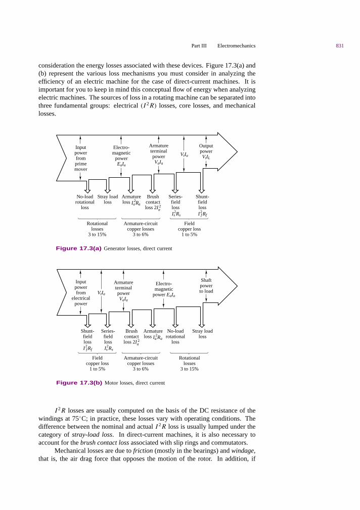
consideration the energy losses associated with these devices. Figure 17.3(a) and(b) represent the various loss mechanisms you must consider in analyzing theefficiency of an electric machine for the case of direct-current machines. It isimportant for you to keep in mind this conceptual flow of energy when analyzingelectric machines. The sources of loss in a rotating machine can be separated intothree fundamental groups: electrical (I 2R) losses, core losses, and mechanicallosses.
OutputpowerVtIL
No-loadrotational
loss
Armatureloss Ia
2Ra
Brushcontactloss 2Ia
2
Series-fieldloss Is
2Rs
Shunt-field lossI2
f Rf
Fieldcopper loss
1 to 5%
Inputpowerfromprimemover
ArmatureterminalpowerVaIa
Electro-magnetic
powerEaIa
VtIa
Stray loadloss
Armature-circuitcopper losses
3 to 6%
Rotationallosses
3 to 15%
Figure 17.3(a) Generator losses, direct current
Shaftpowerto load
No-loadrotational
loss
Armatureloss Ia
2Ra
Brushcontactloss 2Ia
2
Series-fieldloss Is
2Rs
Shunt-field lossI2
f Rf
Fieldcopper loss
1 to 5%
Inputpowerfrom
electricalpower
ArmatureterminalpowerVaIa
Electro-magnetic
power EaIaVtIa
Stray loadloss
Armature-circuitcopper losses
3 to 6%
Rotationallosses
3 to 15%
Figure 17.3(b) Motor losses, direct current
I 2R losses are usually computed on the basis of the DC resistance of thewindings at 75C; in practice, these losses vary with operating conditions. Thedifference between the nominal and actual I 2R loss is usually lumped under thecategory of stray-load loss. In direct-current machines, it is also necessary toaccount for the brush contact loss associated with slip rings and commutators.
Mechanical losses are due to friction (mostly in the bearings) and windage,that is, the air drag force that opposes the motion of the rotor. In addition, if

832 Chapter 17 Introduction to Electric Machines
external devices (e.g., blowers) are required to circulate air through the machinefor cooling purposes, the energy expended by these devices is also included in themechanical losses.
Open-circuit core losses consist of hysteresis and eddy current losses, withonly the excitation winding energized (see Chapter 16 for a discussion of hysteresisand eddy currents). Often these losses are summed with friction and windage lossesto give rise to the no-load rotational loss. The latter quantity is useful if one simplywishes to compute efficiency. Since open-circuit core losses do not account forthe changes in flux density caused by the presence of load currents, an additionalmagnetic loss is incurred that is not accounted for in this term. Stray-load losses areused to lump the effects of nonideal current distribution in the windings and of theadditional core losses just mentioned. Stray-load losses are difficult to determineexactly and are often assumed to be equal to 1.0 percent of the output power forDC machines; these losses can be determined by experiment in synchronous andinduction machines.
The performance of an electric machine can be quantified in a number ofways. In the case of an electric motor, it is usually portrayed in the form of agraphical torque-speed characteristic and efficiency map. The torque-speedcharacteristic of a motor describes how the torque supplied by the machine variesas a function of the speed of rotation of the motor for steady speeds. As we shall seein later sections, the torque-speed curves vary in shape with the type of motor (DC,induction, synchronous) and are very useful in determining the performance of themotor when connected to a mechanical load. Figure 17.4(a) depicts the torque-speed curve of a hypothetical motor. Figure 17.4(b) depicts a typical efficiencymap for a DC machine. It is quite likely that in most engineering applications, theengineer is required to make a decision regarding the performance characteristicsof the motor best suited to a specified task. In this context, the torque-speed curveof a machine is a very useful piece of information.
Torque output(% of rated)
Operatingpoint
Torque-speedcurve of load
To
250
200
150
100
50
0 5001,000
1,5002,000
2,500 nRev/min
0
Electric drive efficiency for OSU FutureCar EM
Torque-speed curve
2000 4000Rev/min
(b) Efficiency map(a) Torque-speed curve
Torq
ue (
Nm
)
6000 8000
0.650.85
0.950.9
0.750.8
0.7
0
20
40
60
80
100
120
140
Figure 17.4 Torque-speed and efficiency curves for an electric motor
The first feature we note of the torque-speed characteristic is that it bears astrong resemblance to the i-v characteristics used in earlier chapters to represent thebehavior of electrical sources. It should be clear that, according to this torque-speed
Part III Electromechanics 833
curve, the motor is not an ideal source of torque (if it were, the curve would appearas a horizontal line across the speed range). One can readily see, for example, thatthe hypothetical motor represented by the curves of Figure 17.4(a) would producemaximum torque in the range of speeds between approximately 800 and 1,400rev/min. What determines the actual speed of the motor (and therefore its outputtorque and power) is the torque-speed characteristic of the load connected to it,much as a resistive load determines the current drawn from a voltage source. Inthe figure, we display the torque-speed curve of a load, represented by the dashedline; the operating point of the motor-load pair is determined by the intersectionof the two curves.
Another important observation pertains to the fact that the motor ofFigure 17.4(a) produces a nonzero torque at zero speed. This fact implies thatas soon as electric power is connected to the motor, the latter is capable of sup-plying a certain amount of torque; this zero-speed torque is called the startingtorque. If the load the motor is connected to requires less than the starting torquethe motor can provide, then the motor can accelerate the load, until the motor speedand torque settle to a stable value, at the operating point. The motor-load pair ofFigure 17.4(a) would behave in the manner just described. However, there maywell be circumstances in which a motor might not be able to provide a sufficientstarting torque to overcome the static load torque that opposes its motion. Thus, wesee that a torque-speed characteristic can offer valuable insight into the operationof a motor. As we proceed to discuss each type of machine in greater detail, weshall devote some time to the discussion of its torque-speed curve.
The efficiency of an electric machine is also an important design and per-formance characteristic. The 1995 Department of Energy Energy Policy Act,also known as EPACT, has required electric motor manufacturers to guarantee aminimum efficiency. The efficiency of an electric motor is usually described usinga contour plot of the efficiency value (a number between 0 and 1) in the torque-speed plane. This representation permits a determination of the motor efficiencyas a function of its performance and operating conditions. Figure 17.4(b) depictsthe efficiency map of an electric drive used in a hybrid-electric vehicle—a 20-kWpermanent magnet AC (or brushless DC) machine. We shall discuss this type ofmachine in Chapter 18. Note that the peak efficiency can be as high as 0.95 (95percent), but that the efficiency decreases significantly away from the optimumpoint (around 3500 rev/min and 45 N-m), to values as low as 0.65.
The most common means of conveying information regarding electric ma-chines is the nameplate. Typical information conveyed by the nameplate is:
1. Type of device (e.g., DC motor, alternator)
2. Manufacturer
3. Rated voltage and frequency
4. Rated current and volt-amperes
5. Rated speed and horsepower
The rated voltage is the terminal voltage for which the machine was designed, andwhich will provide the desired magnetic flux. Operation at higher voltages willincrease magnetic core losses, because of excessive core saturation. The ratedcurrent and rated volt-amperes are an indication of the typical current and powerlevels at the terminal that will not cause undue overheating due to copper losses(I 2R losses) in the windings. These ratings are not absolutely precise, but they give
834 Chapter 17 Introduction to Electric Machines
an indication of the range of excitations for which the motor will perform withoutoverheating. Peak power operation in a motor may exceed rated torque, power,or currents by a substantial factor (up to as much as 6 or 7 times the rated value);however, continuous operation of the motor above the rated performance will causethe machine to overheat, and eventually to sustain damage. Thus, it is importantto consider both peak and continuous power requirements when selecting a motorfor a specific application. An analogous discussion is valid for the speed rating:While an electric machine may operate above rated speed for limited periods oftime, the large centrifugal forces generated at high rotational speeds will eventuallycause undesirable mechanical stresses, especially in the rotor windings, leadingeventually even to self-destruction.
Another important feature of electric machines is the regulation of the ma-chine speed or voltage, depending on whether it is used as a motor or as a generator,respectively. Regulation is the ability to maintain speed or voltage constant in theface of load variations. The ability to closely regulate speed in a motor or voltagein a generator is an important feature of electric machines; regulation is often im-proved by means of feedback control mechanisms, some of which will be brieflyintroduced in this chapter. We shall take the following definitions as being adequatefor the intended purpose of this chapter:
Speed regulation = Speed at no load − Speed at rated load
Speed at rated load(17.4)
Voltage regulation = Voltage at no load − Voltage at rated load
Voltage at rated load(17.5)
Please note that the rated value is usually taken to be the nameplate value, andthat the meaning of load changes depending on whether the machine is a motor,in which case the load is mechanical, or a generator, in which case the load iselectrical.
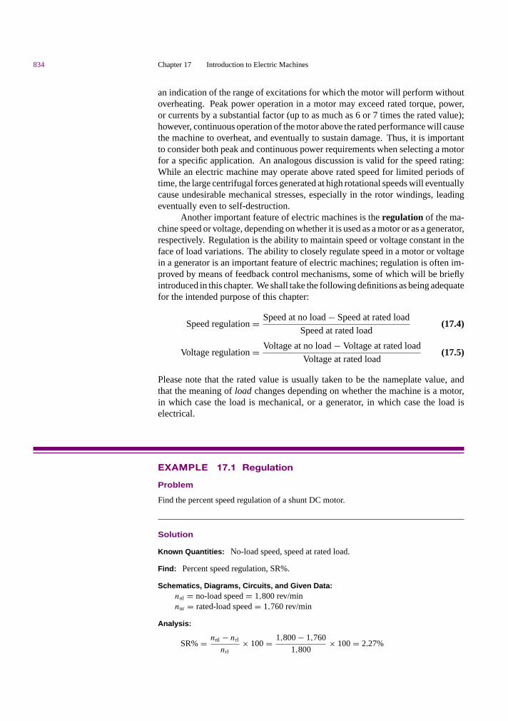
EXAMPLE 17.1 Regulation
Problem
Find the percent speed regulation of a shunt DC motor.
Solution
Known Quantities: No-load speed, speed at rated load.
Find: Percent speed regulation, SR%.
Schematics, Diagrams, Circuits, and Given Data:nnl = no-load speed = 1,800 rev/minnnr = rated-load speed = 1,760 rev/min
Analysis:
SR% = nnl − nrl
nrl× 100 = 1,800 − 1,760
1,800× 100 = 2.27%

Part III Electromechanics 835
Comments: Speed regulation is an intrinsic property of a motor; however, external speedcontrols can be used to regulate the speed of a motor to any (physically achievable)desired value. Some motor control concepts are discussed later in this chapter.
EXAMPLE 17.2 Nameplate Data
Problem
Discuss the nameplate data, shown below, of a typical induction motor.
Solution
Known Quantities: Nameplate data.
Find: Motor characteristics.
Schematics, Diagrams, Circuits, and Given Data: The nameplate appears below.
MODEL 19308 J-X
TYPE CJ4B FRAME 324TS
VOLTS 230/460 C AMB. 40
INS. CL. B
FRT. BRG 210SF EXT. BRG 312SF
SERV 1.0 OPER C-517FACT INSTR
PHASE | 3 Hz | 60 CODE | G WDGS | 1
H.P. 40
R.P.M. 3,565
AMPS 106/53
NEMA NOM. EFF
NOM. P.F.
DUTY CONT. NEMA BDESIGN
Analysis: The nameplate of a typical induction motor is shown in the table above. Themodel number (sometimes abbreviated as MOD) uniquely identifies the motor to themanufacturer. It may be a style number, a model number, an identification number, or aninstruction sheet reference number.
The term frame (sometimes abbreviated as FR) refers principally to the physical sizeof the machine, as well as to certain construction features.
Ambient temperature (abbreviated as AMB, or MAX. AMB) refers to the maximumambient temperature in which the motor is capable of operating. Operation of the motor ina higher ambient temperature may result in shortened motor life and reduced torque.
836 Chapter 17 Introduction to Electric Machines
Insulation class (abbreviated as INS. CL.) refers to the type of insulation used in themotor. Most often used are class A (105C) and class B (130C).
The duty (DUTY), or time rating, denotes the length of time the motor is expected tobe able to carry the rated load under usual service conditions. “CONT.” means that themachine can be operated continuously.
The “CODE” letter sets the limits of starting kVA per horsepower for the machine.There are 19 levels, denoted by the letters A through V, excluding I, O, and Q.
Service factor (abbreviated as SERV FACT) is a term defined by NEMA (theNational Electrical Manufacturers Association) as follows: “The service factor of ageneral-purpose alternating-current motor is a multiplier which, when applied to the ratedhorsepower, indicates a permissible horsepower loading which may be carried under theconditions specified for the service factor.”
The voltage figure given on the nameplate refers to the voltage of the supply circuitto which the motor should be connected. Sometimes two voltages are given, for example,230/460. In this case, the machine is intended for use on either a 230-V or a 460-V circuit.Special instructions will be provided for connecting the motor for each of the voltages.
The term “BRG” indicates the nature of the bearings supporting the motor shaft.
EXAMPLE 17.3 Torque-Speed Curves
Problem
Discuss the significance of the torque-speed curve of an electric motor.
Solution
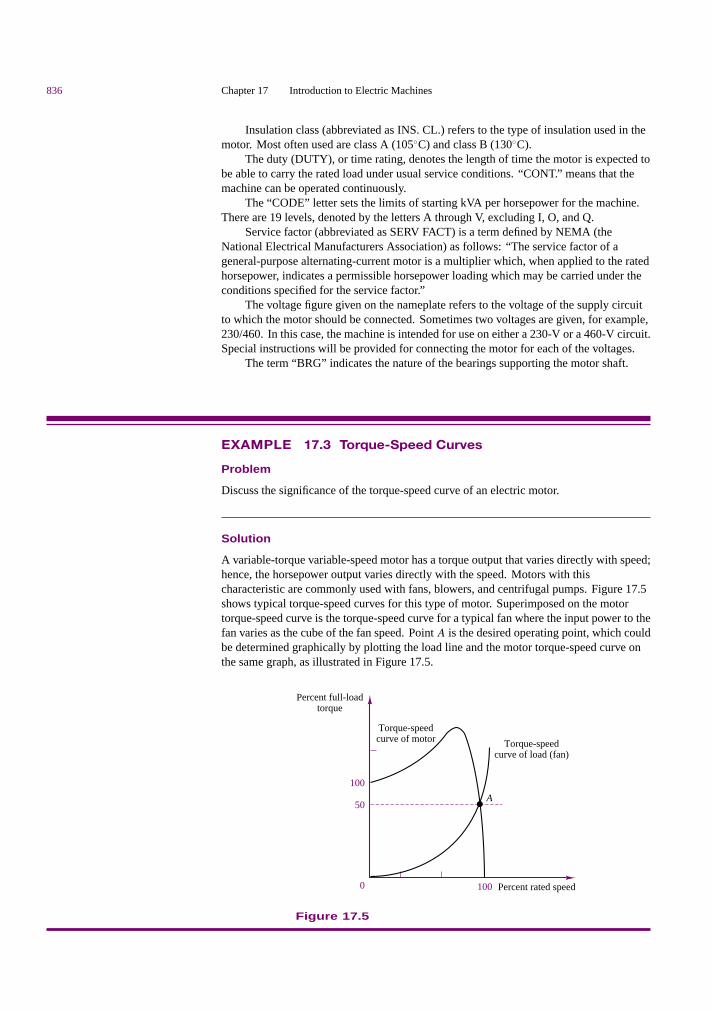
A variable-torque variable-speed motor has a torque output that varies directly with speed;hence, the horsepower output varies directly with the speed. Motors with thischaracteristic are commonly used with fans, blowers, and centrifugal pumps. Figure 17.5shows typical torque-speed curves for this type of motor. Superimposed on the motortorque-speed curve is the torque-speed curve for a typical fan where the input power to thefan varies as the cube of the fan speed. Point A is the desired operating point, which couldbe determined graphically by plotting the load line and the motor torque-speed curve onthe same graph, as illustrated in Figure 17.5.
Percent rated speed
Torque-speedcurve of motor Torque-speed
curve of load (fan)
Percent full-loadtorque
100
50
0
A
100
Figure 17.5

Part III Electromechanics 837
Basic Operation of All Rotating Machines
We have already seen in Chapter 16 how the magnetic field in electromechanicaldevices provides a form of coupling between electrical and mechanical systems.Intuitively, one can identify two aspects of this coupling, both of which play a rolein the operation of electric machines:
1. Magnetic attraction and repulsion forces generate mechanical torque.
2. The magnetic field can induce a voltage in the machine windings (coils) byvirtue of Faraday’s law.
Thus, we may think of the operation of an electric machine in terms of eithera motor or a generator, depending on whether the input power is electrical andmechanical power is produced (motor action), or the input power is mechanicaland the output power is electrical (generator action). Figure 17.6 illustrates thetwo cases graphically.
Electricalpowerinput
Electricalpoweroutput
Mechanicaloutput
Mechanicalinput
(a) Motor action (b) Generator action
TL
T ωm ωmT
TL
Figure 17.6 Generator and motor action in an electric machine
The coupling magnetic field performs a dual role, which may be explainedas follows. When a current i flows through conductors placed in a magneticfield, a force is produced on each conductor, according to equation 17.1. If theseconductors are attached to a cylindrical structure, a torque is generated, and if thestructure is free to rotate, then it will rotate at an angular velocity ωm. As theconductors rotate, however, they move through a magnetic field and cut throughflux lines, thus generating an electromotive force in opposition to the excitation.This emf is also called “counter” emf, as it opposes the source of the current i. If,on the other hand, the rotating element of the machine is driven by a prime mover(for example, an internal combustion engine), then an emf is generated across thecoil that is rotating in the magnetic field (the armature). If a load is connected tothe armature, a current i will flow to the load, and this current flow will in turncause a reaction torque on the armature that opposes the torque imposed by theprime mover.
You see, then, that for energy conversion to take place, two elements arerequired:
1. A coupling field, B, usually generated in the field winding.
2. An armature winding that supports the load current, i, and the emf, e.
Magnetic Poles in Electric Machines
Before discussing the actual construction of a rotating machine, we should spenda few paragraphs to illustrate the significance of magnetic poles in an electric

838 Chapter 17 Introduction to Electric Machines
machine. In an electric machine, torque is developed as a consequence of magneticforces of attraction and repulsion between magnetic poles on the stator and on therotor; these poles produce a torque that accelerates the rotor and a reaction torqueon the stator. Naturally, we would like a construction such that the torque generatedas a consequence of the magnetic forces is continuous and in a constant direction.This can be accomplished if the number of rotor poles is equal to the number ofstator poles. It is also important to observe that the number of poles must be even,since there have to be equal numbers of north and south poles.
The motion and associated electromagnetic torque of an electric machine arethe result of two magnetic fields that are trying to align with each other so that thesouth pole of one field attracts the north pole of the other. Figure 17.7 illustratesthis action by analogy with two permanent magnets, one of which is allowed torotate about its center of mass.
T
γ
Fixed magnet(stator)
Pivoted magnet(rotor)S
N
S
N
Rotortorque
T
N SN
S
Figure 17.7 Alignment action of poles
Figure 17.8 depicts a two-pole machine in which the stator poles are con-structed in such a way as to project closer to the rotor than to the stator structure.This type of construction is rather common, and poles constructed in this fashionare called salient poles. Note that the rotor could also be constructed to havesalient poles.
To understand magnetic polarity, we need to consider the direction of themagnetic field in a coil carrying current. Figure 17.9 shows how the right-handrule can be employed to determine the direction of the magnetic flux. If one wereto grasp the coil with the right hand, with the fingers curling in the direction ofcurrent flow, then the thumb would be pointing in the direction of the magneticflux. Magnetic flux is by convention viewed as entering the south pole and exitingfrom the north pole. Thus, to determine whether a magnetic pole is north or south,we must consider the direction of the flux. Figure 17.10 shows a cross sectionof a coil wound around a pair of salient rotor poles. In this case, one can readilyidentify the direction of the magnetic flux and therefore the magnetic polarity ofthe poles by applying the right-hand rule, as illustrated in the figure.
Often, however, the coil windings are not arranged as simply as in the caseof salient poles. In many machines, the windings are embedded in slots cut intothe stator or rotor, so that the situation is similar to that of the stator depicted in

Part III Electromechanics 839
Excitationcurrent If
Armatureconductors
Reactiontorque
Rotortorque
Field winding
Yoke
Cross section of DC machine
N
S
Pole
++++++
++
++++
•• • • •
••
••
••
•
T
γ
BS
BR
T'
ωm
Figure 17.8 A two-pole machine with salient stator poles
Figure 17.11. This figure is a cross section in which the wire connections between“crosses” and “dots” have been cut away. In Figure 17.11, the dashed line indicatesthe axis of the stator flux according to the right-hand rule, indicating that the slottedstator in effect behaves like a pole pair. The north and south poles indicated inthe figure are a consequence of the fact that the flux exits the bottom part of thestructure (thus, the north pole indicated in the figure) and enters the top half ofthe structure (thus, the south pole). In particular, if you consider that the windingsare arranged so that the current entering the right-hand side of the stator (to theright of the dashed line) flows through the back end of the stator and then flowsoutward from the left-hand side of the stator slots (left of the dashed line), you canvisualize the windings in the slots as behaving in a manner similar to the coils ofFigure 17.10, where the flux axis of Figure 17.11 corresponds to the flux axis ofeach of the coils of Figure 17.10. The actual circuit that permits current flow iscompleted by the front and back ends of the stator, where the wires are connectedaccording to the pattern a-a′, b-b′, c-c′, as depicted in the figure.
i
i
Flux, φ
Direction ofmagnetic flux
Currentpath
Figure 17.9 Right-hand rule
a
c
b'
a'
c'
b
BR
+
+
+
N
S
Figure 17.10 Magneticfield in a salient rotor winding
N
S
× ×
×
×
×
×
×
×
B
Figure 17.11 Magneticfield of stator
Another important consideration that facilitates understanding the operationof electric machines pertains to the use of AC currents. It should be apparent bynow that if the current flowing into the slotted stator is alternating, the direction ofthe flux will also alternate, so that in effect the two poles will reverse polarity everytime the current reverses direction, that is, every half-cycle of the sinusoidal current.Further—since the magnetic flux is approximately proportional to the current inthe coil—as the amplitude of the current oscillates in a sinusoidal fashion, so willthe flux density in the structure. Thus, the magnetic field developed in the statorchanges both spatially and in time.
This property is typical of AC machines, where a rotating magnetic field isestablished by energizing the coil with an alternating current. As we shall see inthe next section, the principles underlying the operation of DC and AC machinesare quite different: in a direct-current machine, there is no rotating field, but amechanical switching arrangement (the commutator) makes it possible for therotor and stator magnetic fields to always align at right angles to each other.

840 Chapter 17 Introduction to Electric Machines
The accompanying CD-ROM includes 2-D “movies” of the most commontypes of electric machines. You might wish to explore these animations to betterunderstand the basic concepts described in this section.
Check Your Understanding17.1 The percent speed regulation of a motor is 10 percent. If the full-load speed is50π rad/s, find (a) the no-load speed in rad/s, and (b) the no-load speed in rev/min.
17.2 The percent voltage regulation for a 250-V generator is 10 percent. Find theno-load voltage of the generator.
17.3 The nameplate of a three-phase induction motor indicates the following values:
H.P. = 10 Volt = 220 V
R.P.M. = 1,750 Service factor = 1.15
Temperature rise = 60C Amp = 30A
Find the rated torque, rated volt-amperes, and maximum continuous output power.
17.4 A motor having the characteristics shown in Figure 17.4 is to drive a load; the loadhas a linear torque-speed curve and requires 150 percent of rated torque at 1,500 rev/min.Find the operating point for this motor-load pair.
17.2 DIRECT-CURRENT MACHINES
As explained in the introductory section, direct-current (DC) machines are easierto analyze than their AC counterparts, although their actual construction is maderather complex by the need to have a commutator, which reverses the directionof currents and fluxes to produce a net torque. The objective of this section isto describe the major construction features and the operation of direct-currentmachines, as well as to develop simple circuit models that are useful in analyzingthe performance of this class of machines.
Physical Structure of DC Machines
A representative DC machine was depicted in Figure 17.8, with the magnetic polesclearly identified, for both the stator and the rotor. Figure 17.12 is a photographof the same type of machine. Note the salient pole construction of the stator andthe slotted rotor. As previously stated, the torque developed by the machine is aconsequence of the magnetic forces between stator and rotor poles. This torqueis maximum when the angle γ between the rotor and stator poles is 90. Also, asyou can see from the figure, in a DC machine the armature is usually on the rotor,and the field winding is on the stator.
To keep this torque angle constant as the rotor spins on its shaft, a mechanicalswitch, called a commutator, is configured so the current distribution in the rotorwinding remains constant and therefore the rotor poles are consistently at 90 withrespect to the fixed stator poles. In a DC machine, the magnetizing current isDC, so that there is no spatial alternation of the stator poles due to time-varyingcurrents. To understand the operation of the commutator, consider the simplifieddiagram of Figure 17.13. In the figure, the brushes are fixed, and the rotor revolvesat an angular velocity ωm; the instantaneous position of the rotor is given by theexpression θ = ωmt − γ .

Part III Electromechanics 841
Polyester impregnated armature for electrical and mechanical integrity
Class H insulation. Custom windings available
Shaft modifications, shaft seals and precisionbalancing available
Large sealed bearingsare standard
NEMA or custommounting faces. Available metric,pump and foot mounts
Permanent magnet fields are more efficient, smaller, lighter and offer wider speed rangethan comparable wound field motors
(a) (c)
Many environmental protectionoptions include customenclosures and finishes,corrosion and fungus proofing
Long life, constant forcebrush springs with fieldreplaceable brushes.Extended life brushsystems available
Rugged, fusedcommutator
TEFC, TENV and open dripproof configurations
Large conduit box – roomywiring compartment for easytermination
Patent anti-cog magnets for smooth low speed operation. High overcurrent capacityand dynamic braking without demag
(b)
Figure 17.12 (a) DC machine; (b) rotor; (c) permanent magnet stator
L3
Brush
θ
ωm
L1
L2
L5
L4 L6
iL iL
Figure 17.13 Rotor winding and commutator
The commutator is fixed to the rotor and is made up in this example of sixsegments that are made of electrically conducting material but are insulated fromeach other. Further, the rotor windings are configured so that they form six coils,connected to the commutator segments as shown in Figure 17.13.
As the commutator rotates counterclockwise, the rotor magnetic field rotateswith it up to θ = 30. At that point, the direction of the current changes in coilsL3 and L6 as the brushes make contact with the next segment. Now the directionof the magnetic field is −30. As the commutator continues to rotate, the directionof the rotor field will again change from −30 to +30, and it will switch again
842 Chapter 17 Introduction to Electric Machines
when the brushes switch to the next pair of segments. In this machine, then, thetorque angle, γ , is not always 90, but can vary by as much as ±30; the actualtorque produced by the machine would fluctuate by as much as ±14 percent, sincethe torque is proportional to sin γ . As the number of segments increases, thetorque fluctuation produced by the commutation is greatly reduced. In a practicalmachine, for example, one might have as many as 60 segments, and the variationof γ from 90 would be only ±3, with a torque fluctuation of less than 1 percent.Thus, the DC machine can produce a nearly constant torque (as a motor) or voltage(as a generator).
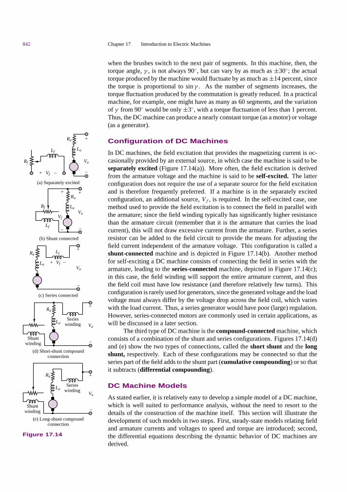
Configuration of DC Machines
In DC machines, the field excitation that provides the magnetizing current is oc-casionally provided by an external source, in which case the machine is said to beseparately excited (Figure 17.14(a)). More often, the field excitation is derivedfrom the armature voltage and the machine is said to be self-excited. The latterconfiguration does not require the use of a separate source for the field excitationand is therefore frequently preferred. If a machine is in the separately excitedconfiguration, an additional source, Vf , is required. In the self-excited case, onemethod used to provide the field excitation is to connect the field in parallel withthe armature; since the field winding typically has significantly higher resistancethan the armature circuit (remember that it is the armature that carries the loadcurrent), this will not draw excessive current from the armature. Further, a seriesresistor can be added to the field circuit to provide the means for adjusting thefield current independent of the armature voltage. This configuration is called ashunt-connected machine and is depicted in Figure 17.14(b). Another methodfor self-exciting a DC machine consists of connecting the field in series with thearmature, leading to the series-connected machine, depicted in Figure 17.14(c);in this case, the field winding will support the entire armature current, and thusthe field coil must have low resistance (and therefore relatively few turns). Thisconfiguration is rarely used for generators, since the generated voltage and the loadvoltage must always differ by the voltage drop across the field coil, which varieswith the load current. Thus, a series generator would have poor (large) regulation.However, series-connected motors are commonly used in certain applications, aswill be discussed in a later section.
+
(a) Separately excited
(b) Shunt connected
(c) Series connected
Ra
La
Vf
Va
–
(d) Short-shunt compoundconnection
(e) Long-shunt compoundconnection
Shuntwinding
Serieswinding
Shuntwinding
+
–
Rf
Lf
Vf
Va
–
+
Va
–
+
+
–
Vf+ –
Lf
Serieswinding Va
–
+
Va
–
+
Ra
La
Ra
La
Ra
La
Lf
Rf
Ra
La
Figure 17.14
The third type of DC machine is the compound-connected machine, whichconsists of a combination of the shunt and series configurations. Figures 17.14(d)and (e) show the two types of connections, called the short shunt and the longshunt, respectively. Each of these configurations may be connected so that theseries part of the field adds to the shunt part (cumulative compounding) or so thatit subtracts (differential compounding).
DC Machine Models
As stated earlier, it is relatively easy to develop a simple model of a DC machine,which is well suited to performance analysis, without the need to resort to thedetails of the construction of the machine itself. This section will illustrate thedevelopment of such models in two steps. First, steady-state models relating fieldand armature currents and voltages to speed and torque are introduced; second,the differential equations describing the dynamic behavior of DC machines arederived.
Part III Electromechanics 843
When a field excitation is established, a magnetic flux, φ, is generated bythe field current, If . From equation 17.2, we know that the torque acting on therotor is proportional to the product of the magnetic field and the current in theload-carrying wire; the latter current is the armature current, Ia (iw, in equation16.2). Assuming that, by virtue of the commutator, the torque angle, γ , is keptvery close to 90, and therefore sin γ = 1, we obtain the following expression forthe torque (in units of N-m) in a DC machine:
T = kT φIa for γ = 90 (17.6)
You may recall that this is simply a consequence of theBli law of Chapter 16. Themechanical power generated (or absorbed) is equal to the product of the machinetorque and the mechanical speed of rotation, ωm (in rad/s), and is therefore givenby
Pm = ωmT = ωmkT φIa (17.7)
Recall now that the rotation of the armature conductors in the field generated bythe field excitation causes a back emf, Eb, in a direction that opposes the rotationof the armature. According to the Blu law (see Chapter 16), then, this back emfis given by the expression
Eb = kaφωm (17.8)
where ka is called the armature constant and is related to the geometry andmagnetic properties of the structure. The voltage Eb represents a countervoltage(opposing the DC excitation) in the case of a motor, and the generated voltage inthe case of a generator. Thus, the electric power dissipated (or generated) by themachine is given by the product of the back emf and the armature current:
Pe = EbIa (17.9)
The constants kT and ka in equations 17.6 and 17.8 are related to geometry factors,such as the dimension of the rotor and the number of turns in the armature winding;and to properties of materials, such as the permeability of the magnetic materials.Note that in the ideal energy-conversion case,Pm = Pe, and therefore ka = kT . Weshall in general assume such ideal conversion of electrical to mechanical energy (orvice versa) and will therefore treat the two constants as being identical: ka = kT .The constant ka is given by
ka = pN
2πM(17.10)
where
p = number of magnetic poles
N = number of conductors per coil
M = number of parallel paths in armature winding
An important observation concerning the units of angular speed must bemade at this point. The equality (under the no-loss assumption) between theconstants ka and kT in equations 17.6 and 17.8 results from the choice of consistentunits, namely, volts and amperes for the electrical quantities, and newton-metersand radians per second for the mechanical quantities. You should be aware that it

844 Chapter 17 Introduction to Electric Machines
is fairly common practice to refer to the speed of rotation of an electric machinein units of revolutions per minute (rev/min).1 In this book, we shall uniformly usethe symbol n to denote angular speed in rev/min; the following relationship shouldbe committed to memory:
n (rev/min) = 60
2πωm (rad/s) (17.11)
If the speed is expressed in rev/min, the armature constant changes as follows:
Eb = k′aφn (17.12)
where
k′a = pN
60M(17.13)
Having introduced the basic equations relating torque, speed, voltages, andcurrents in electric machines, we may now consider the interaction of these quan-tities in a DC machine at steady state, that is, operating at constant speed and fieldexcitation. Figure 17.15 depicts the electrical circuit model of a separately excitedDC machine, illustrating both motor and generator action. It is very important tonote the reference direction of armature current flow, and of the developed torque,in order to make a distinction between the two modes of operation. The fieldexcitation is shown as a voltage, Vf , generating the field current, If , that flowsthrough a variable resistor,Rf , and through the field coil,Lf . The variable resistorpermits adjustment of the field excitation. The armature circuit, on the other hand,consists of a voltage source representing the back emf,Eb, the armature resistance,Ra , and the armature voltage, Va . This model is appropriate both for motor andfor generator action. When Va < Eb, the machine acts as a generator (Ia flowsout of the machine). When Va > Eb, the machine acts as a motor (Ia flows intothe machine). Thus, according to the circuit model of Figure 17.15, the operationof a DC machine at steady state (i.e., with the inductors in the circuit replaced byshort circuits) is described by the following equations:
−If + Vf
Rf
= 0 and Va − RaIa − Eb = 0 (motor action)
−If + Vf
Rf
= 0 and Va + RaIa − Eb = 0 (generator action)
(17.14)
Equation pair 17.14 together with equations 17.6 and 17.8 may be used to determinethe steady-state operating condition of a DC machine.
Ia
Ra
Rf
T
TL
Va
Vf
ωm
LfFieldcircuit
Mechanicalcoupling
Armaturecircuit
(a) Motor reference direction
Eb
_
++ _
Ia
Ra
Rf
T
TL
VaVf
ωm
LfFieldcircuit
Mechanicalcoupling
Armaturecircuit
(b) Generator reference direction
Eb
_
++ _
La
If
If
La
+
–
+
–
Figure 17.15 Electricalcircuit model of a separatelyexcited DC machine
The circuit model of Figure 17.15 permits the derivation of a simple set ofdifferential equations that describe the dynamic analysis of a DC machine. Thedynamic equations describing the behavior of a separately excited DC machineare as follows:
Va(t) − Ia(t)Ra − La
dIa(t)
dt− Eb(t) = 0 (armature circuit) (17.15a)
Vf (t) − If (t)Rf − Lf
dIf (t)
dt= 0 (field circuit) (17.15b)
1Note that the abbreviation RPM, although certainly familiar to the reader, is not a standard unit, andits use should be discouraged.

Part III Electromechanics 845
These equations can be related to the operation of the machine in the presence ofa load. If we assume that the motor is rigidly connected to an inertial load withmoment of inertia J and that the friction losses in the load are represented by aviscous friction coefficient, b, then the torque developed by the machine (in themotor mode of operation) can be written as follows:
T (t) = TL + bωm(t) + Jdωm(t)
dt(17.16)
where TL is the load torque. TL is typically either constant or some function ofspeed, ωm, in a motor. In the case of a generator, the load torque is replaced bythe torque supplied by a prime mover, and the machine torque, T (t), opposes themotion of the prime mover, as shown in Figure 17.15. Since the machine torqueis related to the armature and field currents by equation 17.6, equations 17.16 and17.17 are coupled to each other; this coupling may be expressed as follows:
T (t) = kaφIa(t) (17.17)
or
kaφIa(t) = TL + bωm(t) + Jdωm(t)
dt(17.18)
The dynamic equations described in this section apply to any DC machine. In thecase of a separately excited machine, a further simplification is possible, since theflux is established by virtue of a separate field excitation, and therefore
φ = Nf
R If = kf If (17.19)
whereNf is the number of turns in the field coil, R is the reluctance of the structure,and If is the field current.
17.3 DIRECT-CURRENT GENERATORS
To analyze the performance of a DC generator, it would be useful to obtain an open-circuit characteristic capable of predicting the voltage generated when the machineis driven at a constant speed ωm by a prime mover. The common arrangement is todrive the machine at rated speed by means of a prime mover (or an electric motor).Then, with no load connected to the armature terminals, the armature voltageis recorded as the field current is increased from zero to some value sufficientto produce an armature voltage greater than the rated voltage. Since the loadterminals are open-circuited, Ia = 0 and Eb = Va; and since kaφ = Eb/ωm, themagnetization curve makes it possible to determine the value of kaφ correspondingto a given field current, If , for the rated speed.
Figure 17.16 depicts a typical magnetization curve. Note that the armaturevoltage is nonzero even when no field current is present. This phenomenon is dueto the residual magnetization of the iron core. The dashed lines in Figure 17.16are called field resistance curves and are a plot of the voltage that appears acrossthe field winding plus rheostat (variable resistor; see Figure 17.15) versus the fieldcurrent, for various values of field winding plus rheostat resistance. Thus, theslope of the line is equal to the total field circuit resistance, Rf .
The operation of a DC generator may be readily understood with referenceto the magnetization curve of Figure 17.16. As soon as the armature is connected

846 Chapter 17 Introduction to Electric Machines
Eb (V)
120
100
80
60
0.2 0.4 0.6 0.8 If (A)1.0 1.2 1.4
40
20
0
Figure 17.16 DC machine magnetizationcurve
across the shunt circuit consisting of the field winding and the rheostat, a currentwill flow through the winding, and this will in turn act to increase the emf acrossthe armature. This buildup process continues until the two curves meet, that is,until the current flowing through the field winding is exactly that required to inducethe emf. By changing the rheostat setting, the operating point at the intersection ofthe two curves can be displaced, as shown in Figure 17.16, and the generator cantherefore be made to supply different voltages. The following examples illustratethe operation of the separately excited DC generator.
EXAMPLE 17.4 Separately Excited DC Generator
Problem
A separately excited DC generator is characterized by the magnetization curve ofFigure 17.16.
1. If the prime mover is driving the generator at 800 rev/min, what is the no-loadterminal voltage, Va?
2. If a 1-. load is connected to the generator, what is the generated voltage?
Solution
Known Quantities: Generator magnetization curve and ratings.
Find: Terminal voltage with no load and 1-. load.
Schematics, Diagrams, Circuits, and Given Data:Generator ratings: 100 V, 100 A, 1,000 rev/min.Circuit parameters: Ra = 0.14 .; Vf = 100 V; Rf = 100 ..
Analysis:
1. The field current in the machine is
If = Vf
Rf
= 100 V
100 .= 1 A
From the magnetization curve, it can be seen that this field current will produce

Part III Electromechanics 847
100 V at a speed of 1,000 rev/min. Since this generator is actually running at 800rev/min, the induced emf may be found by assuming a linear relationship betweenspeed and emf. This approximation is reasonable, provided that the departure fromthe nominal operating condition is small. Let n0 and Eb0 be the nominal speed andemf, respectively (i.e., 1,000 rev/min and 100 V); then,
Eb
Eb0= n
n0
and therefore
Eb = n
n0Eb0 = 800 rev/min
1,000 rev/min× 100 V = 80 V
The open-circuit (output) terminal voltage of the generator is equal to the emf fromthe circuit model of Figure 17.15; therefore:
Va = Eb = 80 V
2. When a load resistance is connected to the circuit (the practical situation), theterminal (or load) voltage is no longer equal to Eb, since there will be a voltage dropacross the armature winding resistance. The armature (or load) current may bedetermined from the expression
Ia = IL = Eb
Ra + RL
= 80 V
(0.14 + 1).= 70.2 A
where RL = 1 . is the load resistance. The terminal (load) voltage is therefore givenby
VL = ILRL = 70.2 × 1 = 70.2 V
EXAMPLE 17.5 Separately Excited DC Generator
Problem
Determine the following quantities for a separately excited DC:
1. Induced voltage
2. Machine constant
3. Torque developed at rated conditions
Solution
Known Quantities: Generator ratings and machine parameters.
Find: Eb, ka , T .
Schematics, Diagrams, Circuits, and Given Data:Generator ratings: 1,000 kW; 2,000 V; 3,600 rev/minCircuit parameters: Ra = 0.1 .; flux per pole = φ = 0.5 Wb
Analysis:
1. The armature current may be found by observing that the rated power is equal to theproduct of the terminal (load) voltage and the armature (load) current; thus,
Ia = Prated
VL
= 1,000 × 103
2,000= 500 A

848 Chapter 17 Introduction to Electric Machines
The generated voltage is equal to the sum of the terminal voltage and the voltage dropacross the armature resistance (see Figure 16.14):
Eb = Va + IaRa = 2,000 + 500 × 0.1 = 2,050 V
2. The speed of rotation of the machine in units of rad/s is
ωm = 2πn
60= 2π × 3,600 rev/min
60 s/min= 377 rad/s
Thus, the machine constant is found to be
ka = Eb
φωm
= 2,050 V
0.5 Wb × 377 rad/s= 10.876
V-s
Wb-rad
3. The torque developed is found from equation 16.6:
T = kaφIa = 10.875 V-s/Wb-rad × 0.5 Wb × 500 A = 2,718.9 N-m
Comments: In many practical cases, it is not actually necessary to know the armatureconstant and the flux separately, but it is sufficient to know the value of the product kaφ.For example, suppose that the armature resistance of a DC machine is known and that,given a known field excitation, the armature current, load voltage, and speed of themachine can be measured. Then, the product kaφ may be determined from equation16.20, as follows:
kaφ = Eb
ωm
= VL + Ia(Ra + RS)
ωm
where VL, Ia , and ωm are measured quantities for given operating conditions.
Since the compound-connected generator contains both a shunt and a seriesfield winding, it is the most general configuration, and the most useful for devel-oping a circuit model that is as general as possible. In the following discussion,we shall consider the so-called short-shunt, compound-connected generator, inwhich the flux produced by the series winding adds to that of the shunt winding.Figure 17.17 depicts the equivalent circuit for the compound generator; circuitmodels for the shunt generator and for the rarely used series generator can beobtained by removing the shunt or series field winding element, respectively. Inthe circuit of Figure 17.17, the generator armature has been replaced by a voltagesource corresponding to the induced emf and a series resistance, Ra , correspond-ing to the resistance of the armature windings. The equations describing the DCgenerator at steady state (i.e., with the inductors acting as short circuits) are:
DC Generator Steady-State Equations
Eb = kaφωm V (17.20)
T = P
ωm
= EbIa
ωm
= kaφIa N-m (17.21)
VL = Eb − IaRa − ISRS (17.22)
Ia = IS + If (17.23)

Part III Electromechanics 849
+
–
Rf
Lf
Rx
Ra
Eb
Ia
Va
LS
RS
ILIf
–
+
–
+
VL
ωmPrime mover
La
Ele
ctri
cal
load
Figure 17.17 Compound generator circuitmodel
Note that in the circuit of Figure 17.17, the load and armature voltages are not equal,in general, because of the presence of a series field winding, represented by theresistorRS and by the inductorLS where the subscript “S” stands for “series.” Theexpression for the armature emf is dependent on the air-gap flux, φ, to which theseries and shunt windings in the compound generator both contribute, accordingto the expression
φ = φsh ± φS = φsh ± kSIa (17.24)
Check Your Understanding17.5 A 24-coil, 2-pole DC generator has 16 turns per coil in its armature winding. Thefield excitation is 0.05 Wb per pole, and the armature angular velocity is 180 rad/s. Findthe machine constant and the total induced voltage.
17.6 A 1,000-kW, 1,000-V, 2,400-rev/min separately excited DC generator has an ar-mature circuit resistance of 0.04 .. The flux per pole is 0.4 Wb. Find: (a) the inducedvoltage; (b) the machine constant; and (c) the torque developed at the rated conditions.
17.7 A 100-kW, 250-V shunt generator has a field circuit resistance of 50 . and anarmature circuit resistance of 0.05 .. Find: (a) the full-load line current flowing to theload; (b) the field current; (c) the armature current; and (d) the full-load generator voltage.
17.4 DIRECT-CURRENT MOTORS
DC motors are widely used in applications requiring accurate speed control—forexample, in servo systems. Having developed a circuit model and analysis methodsfor the DC generator, we can extend these results to DC motors, since these arein effect DC generators with the roles of input and output reversed. Once again,we shall analyze the motor by means of both its magnetization curve and a circuitmodel. It will be useful to begin our discussion by referring to the schematicdiagram of a cumulatively compounded motor, as shown in Figure 17.18. Thechoice of the compound-connected motor is the most convenient, since its modelcan be used to represent either a series or a shunt motor with minor modifications.

850 Chapter 17 Introduction to Electric Machines
+
–
Rf
Lf
Rx
Eb
Ia
va
LS
RS
IsIf
–
+
–
+
Vs
ωm
Mechanicalload
Ra
La Supplyvoltage
Figure 17.18 Equivalent circuit of a cumulativelycompounded motor
The equations that govern the behavior of the DC motor follow and aresimilar to those used for the generator. Note that the only differences betweenthese equations and those that describe the DC generator appear in the last twoequations in the group, where the source voltage is equal to the sum of the emfand the voltage drop across the series field resistance and armature resistance, andwhere the source current now equals the sum of the field shunt and armature seriescurrents.
DC Motor Steady-State Equations
Eb = kaφωm (17.25)
T = kaφIa (17.26)
Vs = Eb + IaRa + IsRS (17.27)
Is = If + Ia (17.28)
Note that in these equations we have replaced the symbols VL and IL, used in thegenerator circuit model to represent the generator load current and voltage, withthe symbols Vs and Is , indicating the presence of an external source.
Speed-Torque and Dynamic Characteristics of DCMotors
The Shunt Motor
In a shunt motor (similar to the configuration of Figure 17.18, but with the seriesfield short-circuited), the armature current is found by dividing the net voltageacross the armature circuit (source voltage minus back emf) by the armature re-sistance:
Ia = Vs − kaφωm
Ra
(17.29)
Part III Electromechanics 851
An expression for the armature current may also be obtained from equation 16.26,as follows:
Ia = T
kaφ(17.30)
It is then possible to relate the torque requirements to the speed of the motor bysubstituting equation 17.29 in equation 17.30:
T
kaφ= Vs − kaφωm
Ra
(17.31)
Equation 17.31 describes the steady-state torque-speed characteristic of the shuntmotor. To understand this performance equation, we observe that if Vs, ka, φ, andRa are fixed in equation 17.31 (the flux is essentially constant in the shunt motor fora fixed Vs), then the speed of the motor is directly related to the armature current.Now consider the case where the load applied to the motor is suddenly increased,causing the speed of the motor to drop. As the speed decreases, the armaturecurrent increases, according to equation 17.29. The excess armature current causesthe motor to develop additional torque, according to equation 17.30, until a newequilibrium is reached between the higher armature current and developed torqueand the lower speed of rotation. The equilibrium point is dictated by the balanceof mechanical and electrical power, in accordance with the relation
EbIa = T ωm (17.32)
Thus, the shunt DC motor will adjust to variations in load by changing its speedto preserve this power balance. The torque-speed curves for the shunt motor maybe obtained by rewriting the equation relating the speed to the armature current:
ωm = Vs − IaRa
kaφ= Vs
kaφ− RaT
(kaφ)2(17.33)
To interpret equation 17.33, one can start by considering the motor operatingat rated speed and torque. As the load torque is reduced, the armature current willalso decrease, causing the speed to increase in accordance with equation 17.33. Theincrease in speed depends on the extent of the voltage drop across the armatureresistance, IaRa . The change in speed will be on the same order of magnitudeas this drop; it typically takes values around 10 percent. This corresponds to arelatively good speed regulation, which is an attractive feature of the shunt DCmotor (recall the discussion of regulation in Section 17.1). Normalized torque andspeed vs. power curves for the shunt motor are shown in Figure 17.19. Note that,over a reasonably broad range of powers, up to rated value, the curve is relativelyflat, indicating that the DC shunt motor acts as a reasonably constant-speed motor.
The dynamic behavior of the shunt motor is described by equations 17.15through 17.18, with the additional relation
Ia(t) = Is(t) − If (t) (17.34)
Compound Motors
It is interesting to compare the performance of the shunt motor with that of thecompound-connected motor; the comparison is easily made if we recall that aseries field resistance appears in series with the armature resistance and that the

852 Chapter 17 Introduction to Electric Machines
Shunt
Differential compound
Cumulative compound
Series
PowerRated load power
Torque
PowerRated load power
Speed
(a) (b)
Figure 17.19 DC motor operating characteristics
flux is due to the contributions of both series and shunt fields. Thus, the speedequation becomes
ωm = Vs − Ia(Ra + RS)
ka(φsh ± φS)(17.35)
where
+ in the denominator is for a cumulatively compounded motor.
− in the denominator is for a differentially compounded motor.
φsh is the flux set up by the shunt field winding, assuming that it is constant.
φS is the flux set up by the series field winding, φS = kSIa .
For the cumulatively compound motor, two effects are apparent: the flux is in-creased by the presence of a series component, φS ; and the voltage drop due toIa in the numerator term is increased by an amount proportional to the resistanceof the series field winding, RS . As a consequence, when the load to the motor isreduced, the numerator increases more dramatically than in the case of the shuntmotor, because of the corresponding decrease in armature current, while at thesame time the series flux decreases. Each of these effects causes the speed toincrease; therefore, it stands to reason that the speed regulation of the compound-connected motor is poorer than that of the shunt motor. Normalized torque andspeed vs. power curves for the compound motor (both differential and cumulativeconnections) are shown in Figure 17.19.
The differential equation describing the behavior of a compound motor dif-fers from that for the shunt motor in having additional terms due to the series fieldcomponent:
Vs = Eb(t) + Ia(t)Ra + La
dIa(t)
dt+ Is(t)RS + LS
dIs(t)
dt
= Va(t) + Is(t)RS + LS
dIs(t)
dt
(17.36)
The differential equation for the field circuit can be written as
Va = If (t)(Rf + Rx) + Lf
dIf (t)
dt(17.37)
Part III Electromechanics 853
We also have the following basic relations:
Ia(t) = Is(t) − If (t) (17.38)
and
Eb(t) = kaIa(t)ωm(t) and T (t) = kaφIa(t) (17.39)
Series Motors
The series motor [see Figure 17.14(c)] behaves somewhat differently from theshunt and compound motors because the flux is established solely by virtue of theseries current flowing through the armature. It is relatively simple to derive anexpression for the emf and torque equations for the series motor if we approximatethe relationship between flux and armature current by assuming that the motoroperates in the linear region of its magnetization curve. Then we can write
φ = kSIa (17.40)
and the emf and torque equations become
Eb = kaωmφ = kaωmkSIa (17.41)
T = kaφIa = kakSI2a (17.42)
The circuit equation for the series motor becomes
Vs = Eb + Ia(Ra + RS) = (kaωmkS + RT )Ia (17.43)
where Ra is the armature resistance, RS is the series field winding resistance,and RT is the total series resistance. From equation 17.43, we can solve for Iaand substitute in the torque expression (equation 17.42) to obtain the followingtorque-speed relationship:
T = kakSV 2s
(kaωmkS + RT )2(17.44)
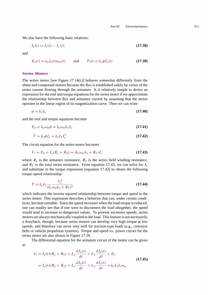
which indicates the inverse squared relationship between torque and speed in theseries motor. This expression describes a behavior that can, under certain condi-tions, become unstable. Since the speed increases when the load torque is reduced,one can readily see that if one were to disconnect the load altogether, the speedwould tend to increase to dangerous values. To prevent excessive speeds, seriesmotors are always mechanically coupled to the load. This feature is not necessarilya drawback, though, because series motors can develop very high torque at lowspeeds, and therefore can serve very well for traction-type loads (e.g., conveyorbelts or vehicle propulsion systems). Torque and speed vs. power curves for theseries motor are also shown in Figure 17.19.
The differential equation for the armature circuit of the motor can be givenas
Vs = Ia(t)(Ra + RS) + La
dIa(t)
dt+ LS
dIa(t)
dt+ Eb
= Ia(t)(Ra + RS) + La
dIa(t)
dt+ LS
dIa(t)
dt+ kakSIaωm
(17.45)
854 Chapter 17 Introduction to Electric Machines
Permanent-Magnet DC Motors
Permanent-magnet (PM) DC motors have become increasingly common in appli-cations requiring relatively low torques and efficient use of space. The constructionof PM direct-current motors differs from that of the motors considered thus far inthat the magnetic field of the stator is produced by suitably located poles madeof magnetic materials. Thus, the basic principle of operation, including the ideaof commutation, is unchanged with respect to the wound-stator DC motor. Whatchanges is that there is no need to provide a field excitation, whether separatelyor by means of the self-excitation techniques discussed in the preceding sections.Therefore, the PM motor is intrinsically simpler than its wound-stator counterpart.
The equations that describe the operation of the PM motor follow. Thetorque produced is related to the armature current by a torque constant, kPM, whichis determined by the geometry of the motor:
T = kT PMIa (17.46)
As in the conventional DC motor, the rotation of the rotor produces the usualcounter or back emf, Eb, which is linearly related to speed by a voltage constant,kaPM :
Eb = kaPMωm (17.47)
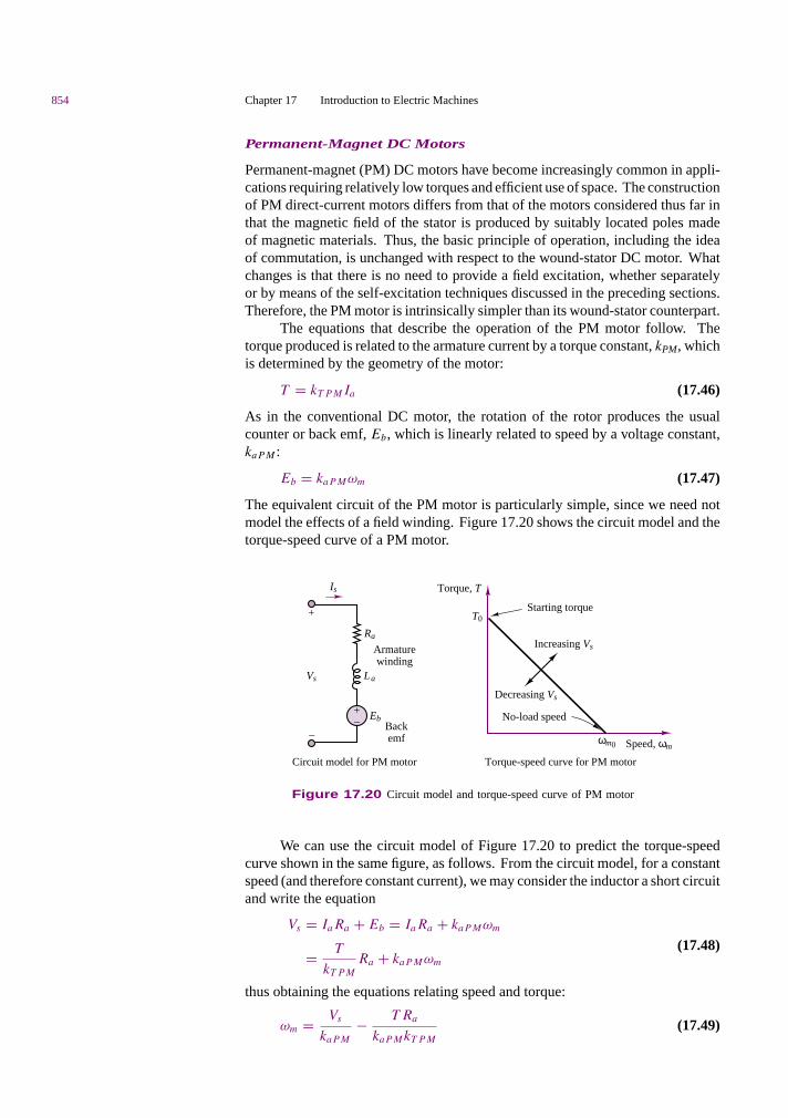
The equivalent circuit of the PM motor is particularly simple, since we need notmodel the effects of a field winding. Figure 17.20 shows the circuit model and thetorque-speed curve of a PM motor.
La
Ra
Torque, T
Starting torque
Increasing Vs
T0
Decreasing Vs
+
–
No-load speed
Speed, ωm ωm0
Vs
Eb
Circuit model for PM motor Torque-speed curve for PM motor
+_
Armaturewinding
Backemf
Is
Figure 17.20 Circuit model and torque-speed curve of PM motor
We can use the circuit model of Figure 17.20 to predict the torque-speedcurve shown in the same figure, as follows. From the circuit model, for a constantspeed (and therefore constant current), we may consider the inductor a short circuitand write the equation
Vs = IaRa + Eb = IaRa + kaPMωm
= T
kT PMRa + kaPMωm
(17.48)
thus obtaining the equations relating speed and torque:
ωm = Vs
kaPM− T Ra
kaPMkT PM(17.49)

Part III Electromechanics 855
and
T = Vs
Ra
kT PM − ωm
Ra
kaPMkT PM (17.50)
From these equations, one can extract the stall torque, T0, that is, the zero-speedtorque:
T0 = Vs
Ra
kT PM (17.51)
and the no-load speed, ωm0:
ωm0 = Vs
kaPM(17.52)
Under dynamic conditions, assuming an inertia plus viscous friction load, thetorque produced by the motor can be expressed as
T = kT PMIa(t) = Tload(t) + dωm(t) + Jdωm(t)
dt(17.53)
The differential equation for the armature circuit of the motor is therefore givenby:
Vs = Ia(t)Ra + La
dIa(t)
dt+ Eb
= Ia(t)Ra + La
dIa(t)
dt+ kaPMωm(t)
(17.54)
The fact that the air-gap flux is constant in a permanent-magnet DC motormakes its characteristics somewhat different from those of the wound DC motor.A direct comparison of PM and wound-field DC motors reveals the followingadvantages and disadvantages of each configuration.
Comparison of Wound-Field and PM DC Motors
1. PM motors are smaller and lighter than wound motors for a givenpower rating. Further, their efficiency is greater because there are nofield winding losses.
2. An additional advantage of PM motors is their essentially linearspeed-torque characteristic, which makes analysis (and control) mucheasier. Reversal of rotation is also accomplished easily, by reversingthe polarity of the source.
3. A major disadvantage of PM motors is that they can becomedemagnetized by exposure to excessive magnetic fields, application ofexcessive voltage, or operation at excessively high or low temperatures.
4. A less obvious drawback of PM motors is that their performance issubject to greater variability from motor to motor than is the case forwound motors, because of variations in the magnetic materials.
In summary, four basic types of DC motors are commonly used. Their prin-cipal operating characteristics are summarized as follows, and their general torqueand speed versus power characteristics are depicted in Figure 17.19, assumingmotors with identical voltage, power, and speed ratings.

856 Chapter 17 Introduction to Electric Machines
Shunt wound motor: Field connected in parallel with the armature. Withconstant armature voltage and field excitation, the motor has good speedregulation (flat speed-torque characteristic).
Compound wound motor: Field winding has both series and shuntcomponents. This motor offers better starting torque than the shunt motor,but worse speed regulation.
Series wound motor: The field winding is in series with the armature. Themotor has very high starting torque and poor speed regulation. It is usefulfor low-speed, high-torque applications.
Permanent-magnet motor: Field windings are replaced by permanentmagnets. The motor has adequate starting torque, with speed regulationsomewhat worse than that of the compound wound motor.
EXAMPLE 17.6 DC Shunt Motor Analysis
Problem
Find the speed and torque generated by a four-pole DC shunt motor.
Solution
Known Quantities: Motor ratings; circuit and magnetic parameters.
Find: ωm, T .
Schematics, Diagrams, Circuits, and Given Data:Motor ratings: 3 hp; 240 V; 120 rev/min.Circuit and magnetic parameters: IS = 30 A; If = 1.4 A; Ra = 0.6 .; φ = 20 mWb;N = 1,000; M = 4 (see equation 17.10).
Analysis: We convert the power to SI units:
PRATED = 3 hp × 746W
hp= 2.238 W
Next, we compute the armature current as the difference between source and field current(equation 17.34):
Ia = Is − If = 30 − 1.4 = 28.6 A
The no-load armature voltage, Eb, is given by:
Eb = Vs − IaRa = 240 − 28.6 × 0.6 = 222.84 V
and equation 17.10 can be used to determine the armature constant:
ka = pN
2πM= 4 × 1000
2π × 4= 159.15
V-s
Wb-rad
Knowing the motor constant, we can calculate the speed, after equation 17.25:
ωm = Ea
kaφ= 222.84 V
159.15V-s
Wb-rad× 0.002 Wb
= 70rad
s
Finally, the torque developed by the motor can be found as the ratio of the power to the

Part III Electromechanics 857
angular velocity:
T = P
ωm
= 2,238 W
70rad
s
= 32 N-m
EXAMPLE 17.7 DC Shunt Motor Analysis
Problem
Determine the following quantities for the DC shunt motor, connected as shown in thecircuit Figure 17.21:
1. Field current required for full-load operation
2. No-load speed
3. Plot the speed torque curve of the machine in the range from no-load torque to ratedtorque
4. Power output at rated torque.
Is Ia
Vs
If
Rf
Rx
Ra
Eb
+
–
Figure 17.21 Shunt motorconfiguration
Em
f (v
olts
)
Field current (amps)
8
0.1 0.2 0.3 0.4 0.5 0.6 0.7 0.8 0.9 1.0
7
6
5
4
3
2
1
0
Figure 17.22 Magnetization curve for asmall DC motor
Solution
Known Quantities: Magnetization curve, rated current, rated speed, circuit parameters.
Find: If ; nno-load; T -n curve, Prated.
Schematics, Diagrams, Circuits, and Given Data: Figure 17.22 (magnetization curve)Motor ratings: 8 A, 120 rev/minCircuit parameters: Ra = 0.2 .; Vs = 7.2 V; N = number of coil turns in winding = 200
Analysis:
1. To find the field current, we must find the generated emf since Rf is not known.Writing KVL around the armature circuit, we obtain
Vs = Eb + IaRa
Eb = Vs − IaRa = 7.2 − 8(0.2) = 5.6 V
858 Chapter 17 Introduction to Electric Machines
Having found the back emf, we can find the field current from the magnetizationcurve. At Eb = 5.6 V, we find that the field current and field resistance are
If = 0.6 A and Rf = 7.2
0.6= 12 .
2. To obtain the no-load speed, we use the equations
Eb = kaφ2πn
60T = kaφIa
leading to
Vs = IaRa + Eb = IaRa + kaφ2π
60n
or
n = Vs − IaRa
kaφ(2π/60)
At no load, and assuming no mechanical losses, the torque is zero, and we see that thecurrent Ia must also be zero in the torque equation (T = kaφIa). Thus, the motorspeed at no load is given by
nno-load = Vs
kaφ(2π/60)
We can obtain an expression for kaφ knowing that, at full load,
Eb = 5.6 V = kaφ2πn
60
so that, for constant field excitation,
kaφ = Eb
(60
2πn
)= 5.6
(60
2π(120)
)= 0.44563
V · s
rad
Finally, we may solve for the no-load speed, in rev/min:
nno-load = Vs
kaφ(2π/60)= 7.2
(0.44563)(2π/60)
= 154.3 rev/min
3. The torque at rated speed and load may be found as follows:
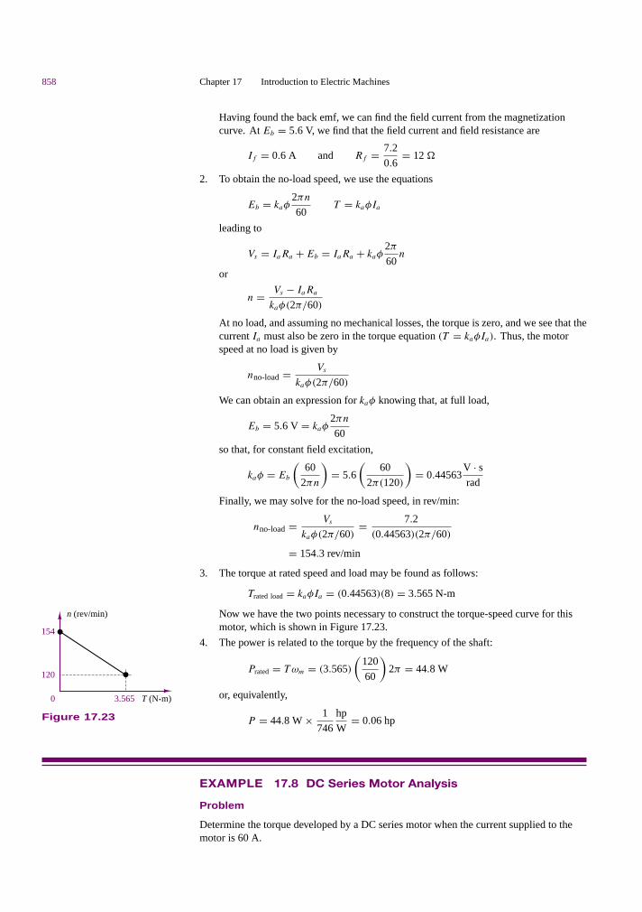
Trated load = kaφIa = (0.44563)(8) = 3.565 N-m
Now we have the two points necessary to construct the torque-speed curve for thismotor, which is shown in Figure 17.23.
4. The power is related to the torque by the frequency of the shaft:
Prated = T ωm = (3.565)
(120
60
)2π = 44.8 W
or, equivalently,
P = 44.8 W × 1
746
hp
W= 0.06 hp
154
120
0 3.565 T (N.m)
n (rev/min)
Figure 17.23
EXAMPLE 17.8 DC Series Motor Analysis
Problem
Determine the torque developed by a DC series motor when the current supplied to themotor is 60 A.
Part III Electromechanics 859
Solution
Known Quantities: Motor ratings; operating conditions.
Find: T60, torque delivered at 60-A series current.
Schematics, Diagrams, Circuits, and Given Data: Motor ratings: 10 hp; 115 V; fullload speed = 1,800 rev/minOperating conditions: motor draws 40 A
Assumptions: The motor operates in the linear region of the magnetization curve.
Analysis: Within the linear region of operation, the flux per pole is directly proportionalto the current in the field winding. That is,
φ = kSIa
The full-load speed is
n = 1,800 rev/min
or
ωm = 2πn
60= 60π rad/s
Rated output power is
Prated = 10 hp × 746 W/hp = 7,460 W
and full-load torque is
T40A = Prated
ωm
= 7,460
60π= 39.58 N-m
Thus, the machine constant may be computed from the torque equation for the seriesmotor:
T = kakSI2a = KI 2
a
At full load,
K = kakS = 39.58 N-m
402 A2 = 0.0247N-m
A2
and we can compute the torque developed for a 60-A supply current to be
T60A = KI 2a = 0.0247 × 602 = 88.92 N-m
EXAMPLE 17.9 Dynamic Response of PM DC Motor
Problem
Develop a set of differential equations and a transfer function describing the dynamicresponse of the motor angular velocity of a PM DC motor connected to a mechanical load.
Solution
Known Quantities: PM DC motor circuit model; mechanical load model.
Find: Differential equations and transfer functions of electromechanical system.

860 Chapter 17 Introduction to Electric Machines
Analysis: The dynamic response of the electromechanical system can be determined byapplying KVL to the electrical circuit (Figure 17.20), and Newton’s second law to themechanical system. These equations will be coupled to one another, as you shall see,because of the nature of the motor back emf and torque equations.
Applying KVL and equation 17.47 to the electrical circuit we obtain:
VL(t) − RaIa(t) − La
dIa(t)
dt− Eb(t) = 0
or
La
dIa(t)
dt+ RaIa(t) + KaPMωm(t) = VL(t)
Applying Newton’s second law and equation 17.46 to the load inertia, we obtain:
Jdω(t)
dt= T (t) − Tload(t) − bω
or
−KT PMIa(t) + Jdω(t)
dt+ bω(t) = Tload(t)
These two differential equations are coupled because the first depends on ωm and thesecond on Ia . Thus, they need to be solved simultaneously.
To derive the transfer function, we Laplace-transform the two equations to obtain:
(sLa + Ra)Ia(s) + KaPM.(s) = VL(s)
−KT PMIa(s) + (sJ + b).(s) = Tload(s)
We can write the above equations in matrix form and resort to Cramer’s rule to solve for.m(s) as a function of VL(s) and Tload(s).[
(sLa + Ra) KaPM
−KT PM (sL + b)
] [Ia(s)
.m(s)
]=
[VL(s)
Tload(s)
]
with solution
.m(s) =det
[(sLa + Ra) VL(s)
KT PM Tload(s)
]
det
[(sLa + Ra) Ka PM
−KT PM (sJ + b)
]
or
.m(s) = (sLa + Ra)
(sLa + Ra)(sJ + b) + Ka PMKT PMTload(s)
+ KT PM
(sLa + Ra)(sJ + b) + Ka PMKT PMVL(s)
Comments: Note that the dynamic response of the motor angular velocity depends onboth the input voltage and on the load torque. This problem is explored further in thehomework problems.
DC Drives and DC Motor Speed Control
The advances made in power semiconductors have made it possible to realize low-cost speed control systems for DC motors. The basic operation of controlledrectifier and chopper drives for DC motors was described in Chapter 11. In thepresent section we describe some of the considerations that are behind the choiceof a specific drive type, and of some of the loads that are likely to be encountered.

Part III Electromechanics 861
Constant-torque loads are quite common, and are characterized by a needfor constant torque over the entire speed range. This need is usually due to friction;the load will demand increasing horsepower at higher speeds, since power is theproduct of speed and torque. Thus, the power required will increase linearly withspeed. This type of loading is characteristic of conveyors, extruders, and surfacewinders.
Another type of load is one that requires constant horsepower over the speedrange of the motor. Since torque is inversely proportional to speed with constanthorsepower, this type of load will require higher torque at low speeds. Examplesof constant-horsepower loads are machine tool spindles (e.g., lathes). This typeof application requires very high starting torques.
Variable-torque loads are also common. In this case, the load torque isrelated to the speed in some fashion, either linearly or geometrically. For someloads, for example, torque is proportional to the speed (and thus horsepower isproportional to speed squared); examples of loads of this type are positive dis-placement pumps. More common than the linear relationship is the squared-speeddependence of inertial loads such as centrifugal pumps, some fans, and all loadsin which a flywheel is used for energy storage.
To select the appropriate motor and adjustable speed drive for a given appli-cation, we need to examine how each method for speed adjustment operates on aDC motor. Armature voltage control serves to smoothly adjust speed from 0 to 100percent of the nameplate rated value (i.e., base speed), provided that the field exci-tation is also equal to the rated value. Within this range, it is possible to fully controlmotor speed for a constant-torque load, thus providing a linear increase in horse-power, as shown in Figure 17.24. Field weakening allows for increases in speedof up to several times the base speed; however, field control changes the character-istics of the DC motor from constant torque to constant horsepower, and thereforethe torque output drops with speed, as shown in Figure 17.24. Operation abovebase speed requires special provision for field control, in addition to the circuitryrequired for armature voltage control, and is therefore more complex and costly.
Torque (% rated)
Speed(% rated)
Armaturecontrol
Base speed200100 300 400 500
100
Field control
Horsepower (% rated)
Speed(% rated)Base speed
200100 300 400 500
100
Field control
Armaturecontrol
Figure 17.24 Speed control in DC motors
Check Your Understanding17.8 A series motor draws a current of 25 A and develops a torque of 100 N-m Find:(a) the torque when the current rises to 30 A if the field is unsaturated; and (b) the torquewhen the current rises to 30 A and the increase in current produces a 10 percent increase influx.
17.9 A 200-V DC shunt motor draws 10 A at 1,800 rev/min. The armature circuitresistance is 0.15 . and the field winding resistance is 350 .. What is the torque developedby the motor?

862 Chapter 17 Introduction to Electric Machines
17.10 Describe the cause-and-effect behavior of the speed control method of changingarmature voltage for a shunt DC motor.
17.5 AC MACHINES
From the previous sections, it should be apparent that it is possible to obtain awide range of performance characteristics from DC machines, as both motorsand generators. A logical question at this point should be, Would it not be moreconvenient in some cases to take advantage of the single- or multiphase AC powerthat is available virtually everywhere than to expend energy and use additionalhardware to rectify and regulate the DC supplies required by direct-current motors?The answer to this very obvious question is certainly a resounding yes. In fact,the AC induction motor is the workhorse of many industrial applications, andsynchronous generators are used almost exclusively for the generation of electricpower worldwide. Thus, it is appropriate to devote a significant portion of thischapter to the study of AC machines, and of induction motors in particular. Theobjective of this section is to explain the basic operation of both synchronous andinduction machines, and to outline their performance characteristics. In doing so,we shall also point out the relative advantages and disadvantages of these machinesin comparison with direct-current machines. The motor “movies” included in theCD-ROM may help you visualize the operation of AC machines.
Rotating Magnetic Fields
As mentioned in Section 17.1, the fundamental principle of operation of AC ma-chines is the generation of a rotating magnetic field, which causes the rotor to turnat a speed that depends on the speed of rotation of the magnetic field. We shallnow explain how a rotating magnetic field can be generated in the stator and airgap of an AC machine by means of AC currents.
N
S
a
c b
a'
c'b'
ia
ib
ic
Statorwindings
×
×
×
a'
b'
c'
BSVf
a
b
c
+
–
n
Figure 17.25 Two-polethree-phase stator
Consider the stator shown in Figure 17.25, which supports windings a-a′,b-b′ and c-c′. The coils are geometrically spaced 120 apart, and a three-phasevoltage is applied to the coils. As you may recall from the discussion of AC powerin Chapter 7, the currents generated by a three-phase source are also spaced by120, as illustrated in Figure 17.26. The phase voltages referenced the neutral
–150
–100
–50
150
100
50
0
0.02 0.025 0.03 0.035
t1 t3t2 Time (s)0 0.005 0.01 0.015
Am
ps
ia ib ic
Figure 17.26 Three-phase stator winding currents

Part III Electromechanics 863
terminal, would then be given by the expressions
va = A cos(ωet)
vb = A cos
(ωet − 2π
3
)
vc = A cos
(ωet + 2π
3
)
where ωe is the frequency of the AC supply, or line frequency. The coils in eachwinding are arranged in such a way that the flux distribution generated by any onewinding is approximately sinusoidal. Such a flux distribution may be obtained byappropriately arranging groups of coils for each winding over the stator surface.Since the coils are spaced 120 apart, the flux distribution resulting from the sum ofthe contributions of the three windings is the sum of the fluxes due to the separatewindings, as shown in Figure 17.27. Thus, the flux in a three-phase machinerotates in space according to the vector diagram of Figure 17.28, and is constant inamplitude. A stationary observer on the machine’s stator would see a sinusoidallyvarying flux distribution as shown in Figure 17.27.
Wb
Degrees
1
2
0
–1
–2200100 400300 500 600 7000
Net fluxφbφa
φc
Figure 17.27 Flux distribution in a three-phase statorwinding as a function of angle of rotation
+
+
+
+
+
+ + +
+
φc
θ1
θ3
θ2
φ
t = t1 t = t2 t = t3
φa
φb
–
–
– φc
φ
φa
φb
–
–
–
φa
φb
φc
φ
–
–
–
Figure 17.28 Rotating flux in a three-phase machine
Since the resultant flux of Figure 17.27 is generated by the currents of Figure17.26, the speed of rotation of the flux must be related to the frequency of thesinusoidal phase currents. In the case of the stator of Figure 17.25, the numberof magnetic poles resulting from the winding configuration is two; however, it isalso possible to configure the windings so that they have more poles. For example,Figure 17.29 depicts a simplified view of a four-pole stator. ×
×
× ×
× ×
B
S
ωm
S
N
N
B
Figure 17.29 Four-polestator
In general, the speed of the rotating magnetic field is determined by thefrequency of the excitation current, f , and by the number of poles present in thestator, p, according to the equation
ns = 120f
prev/min
or (17.55)
ωs = 2πnS60
= 2π × 2f
p
where ns (or ωs) is usually called the synchronous speed.

864 Chapter 17 Introduction to Electric Machines
Now, the structure of the windings in the preceding discussion is the samewhether the AC machine is a motor or a generator; the distinction between the twodepends on the direction of power flow. In a generator, the electromagnetic torqueis a reaction torque that opposes rotation of the machine; this is the torque againstwhich the prime mover does work. In a motor, on the other hand, the rotational(motional) voltage generated in the armature opposes the applied voltage; thisvoltage is the counter (or back) emf. Thus, the description of the rotating magneticfield given thus far applies to both motor and generator action in AC machines.
As described a few paragraphs earlier, the stator magnetic field rotates in anAC machine, and therefore the rotor cannot “catch up” with the stator field and isin constant pursuit of it. The speed of rotation of the rotor will therefore depend onthe number of magnetic poles present in the stator and in the rotor. The magnitudeof the torque produced in the machine is a function of the angle γ between thestator and rotor magnetic fields; precise expressions for this torque depend on howthe magnetic fields are generated and will be given separately for the two cases ofsynchronous and induction machines. What is common to all rotating machinesis that the number of stator and rotor poles must be identical if any torque is to begenerated. Further, the number of poles must be even, since for each north polethere must be a corresponding south pole.
One important desired feature in an electric machine is an ability to generatea constant electromagnetic torque. With a constant-torque machine, one can avoidtorque pulsations that could lead to undesired mechanical vibration in the motoritself and in other mechanical components attached to the motor (e.g., mechanicalloads, such as spindles or belt drives). A constant torque may not always beachieved, although it will be shown that it is possible to accomplish this goal whenthe excitation currents are multiphase. A general rule of thumb, in this respect, isthat it is desirable, insofar as possible, to produce a constant flux per pole.
17.6 THE ALTERNATOR (SYNCHRONOUSGENERATOR)
One of the most common AC machines is the synchronous generator, or alterna-tor. In this machine, the field winding is on the rotor, and the connection is madeby means of brushes, in an arrangement similar to that of the DC machines studiedearlier. The rotor field is obtained by means of a DC current provided to the rotorwinding, or by permanent magnets. The rotor is then connected to a mechanicalsource of power and rotates at a speed that we will consider constant to simplifythe analysis.
Figure 17.30 depicts a two-pole three-phase synchronous machine. Figure17.31 depicts a four-pole three-phase alternator, in which the rotor poles are gen-erated by means of a wound salient pole configuration and the stator poles are theresult of windings embedded in the stator according to the simplified arrangementshown in the figure, where each of the pairs a/a′, b/b′, and so on, contributesto the generation of the magnetic poles, as follows. The group a/a′, b/b′, c/c′
produces a sinusoidally distributed flux (see Figure 17.27) corresponding to oneof the pole pairs, while the group −a/ − a′, −b/ − b′, −c/ − c′ contributes theother pole pair. The connections of the coils making up the windings are alsoshown in Figure 17.31. Note that the coils form a wye connection (see Chap-ter 7). The resulting flux distribution is such that the flux completes two sinusoidalcycles around the circumference of the air gap. Note also that each arm of the

Part III Electromechanics 865
Salient pole machine
S
N
a
b c
a'
b'c'
Cylindrical rotor machine
a
b c
a'
b'c'
S
N
Slip rings
Brushes
3 phase AC
+ –Ia
a
If
Ib
IcStator
Rotor
b c
+ –
If
a'
b'c'
Vfa
b
c
Vf
Figure 17.30 Two-pole synchronous machine
S
S
b
a c
a'
b'
c'
–a
–b
–c
–a'
–b'
–c'–b
–a
a
Statorb
cb
c
a'
–b'
–c
a
–a'
b'c'
–c'
Ib
Ic
Ia
I
N N
Figure 17.31 Four-pole three-phase alternator
three-phase wye connection has been divided into two coils, wound in differentlocations, according to the schematic stator diagram of Figure 17.31. One couldthen envision analogous configurations with greater numbers of poles, obtainedin the same fashion, that is, by dividing each arm of a wye connection into morewindings.
The arrangement shown in Figure 17.31 requires that a further distinction bemade between mechanical degrees, θm, and electrical degrees, θe. In the four-polealternator, the flux will see two complete cycles during one rotation of the rotor,and therefore the voltage that is generated in the coils will also oscillate at twicethe frequency of rotation. In general, the electrical degrees (or radians) are relatedto the mechanical degrees by the expression
θe = p
2θm (17.56)
where p is the number of poles. In effect, the voltage across a coil of the machinegoes through one cycle every time a pair of poles moves past the coil. Thus, the
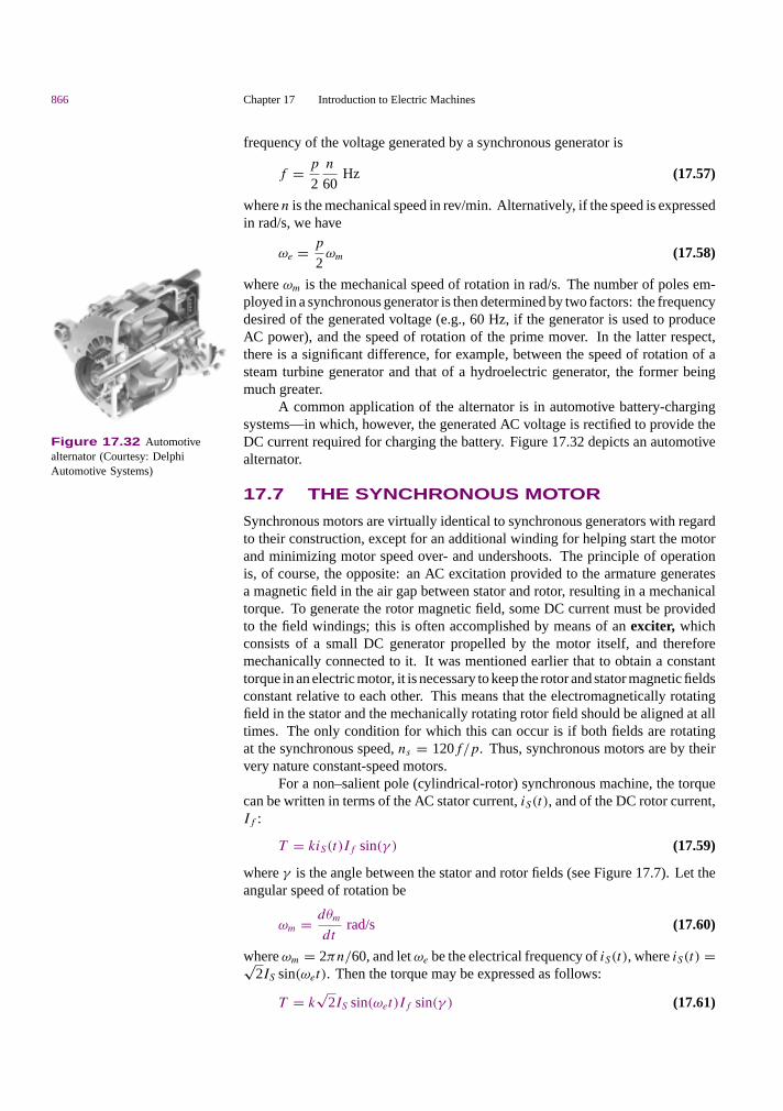
866 Chapter 17 Introduction to Electric Machines
frequency of the voltage generated by a synchronous generator is
f = p
2
n
60Hz (17.57)
where n is the mechanical speed in rev/min. Alternatively, if the speed is expressedin rad/s, we have
ωe = p
2ωm (17.58)
where ωm is the mechanical speed of rotation in rad/s. The number of poles em-ployed in a synchronous generator is then determined by two factors: the frequencydesired of the generated voltage (e.g., 60 Hz, if the generator is used to produceAC power), and the speed of rotation of the prime mover. In the latter respect,there is a significant difference, for example, between the speed of rotation of asteam turbine generator and that of a hydroelectric generator, the former beingmuch greater.
A common application of the alternator is in automotive battery-chargingsystems—in which, however, the generated AC voltage is rectified to provide theDC current required for charging the battery. Figure 17.32 depicts an automotivealternator.
Figure 17.32 Automotivealternator (Courtesy: DelphiAutomotive Systems)
17.7 THE SYNCHRONOUS MOTOR
Synchronous motors are virtually identical to synchronous generators with regardto their construction, except for an additional winding for helping start the motorand minimizing motor speed over- and undershoots. The principle of operationis, of course, the opposite: an AC excitation provided to the armature generatesa magnetic field in the air gap between stator and rotor, resulting in a mechanicaltorque. To generate the rotor magnetic field, some DC current must be providedto the field windings; this is often accomplished by means of an exciter, whichconsists of a small DC generator propelled by the motor itself, and thereforemechanically connected to it. It was mentioned earlier that to obtain a constanttorque in an electric motor, it is necessary to keep the rotor and stator magnetic fieldsconstant relative to each other. This means that the electromagnetically rotatingfield in the stator and the mechanically rotating rotor field should be aligned at alltimes. The only condition for which this can occur is if both fields are rotatingat the synchronous speed, ns = 120f/p. Thus, synchronous motors are by theirvery nature constant-speed motors.
For a non–salient pole (cylindrical-rotor) synchronous machine, the torquecan be written in terms of the AC stator current, iS(t), and of the DC rotor current,If :
T = kiS(t)If sin(γ ) (17.59)
where γ is the angle between the stator and rotor fields (see Figure 17.7). Let theangular speed of rotation be
ωm = dθm
dtrad/s (17.60)
whereωm = 2πn/60, and letωe be the electrical frequency of iS(t), where iS(t) =√2IS sin(ωet). Then the torque may be expressed as follows:
T = k√
2IS sin(ωet)If sin(γ ) (17.61)

Part III Electromechanics 867
where k is a machine constant, IS is the rms value of the stator current, and If isthe DC rotor current. Now, the rotor angle γ can be expressed as a function oftime by
γ = γ0 + ωmt (17.62)
where γ0 is the angular position of the rotor at t = 0; the torque expression thenbecomes
T = k√
2ISIf sin(ωet) sin(ωmt + γ0)
= k
√2
2ISIf cos[(ωm − ωe)t − γ0] − cos[(ωm + ωe)t + γ0]
(17.63)
It is a straightforward matter to show that the average value of this torque, 〈T 〉, isdifferent from zero only if ωm = ±ωe, that is, only if the motor is turning at thesynchronous speed. The resulting average torque is then given by
〈T 〉 = k√
2ISIf cos(γ0) (17.64)
Note that equation 17.63 corresponds to the sum of an average torque plus afluctuating component at twice the original electrical (or mechanical) frequency.The fluctuating component results because, in the foregoing derivation, a single-phase current was assumed. The use of multiphase currents reduces the torquefluctuation to zero and permits the generation of a constant torque.
A per-phase circuit model describing the synchronous motor is shown inFigure 17.33, where the rotor circuit is represented by a field winding equiva-lent resistance and inductance, Rf and Lf , respectively, and the stator circuit isrepresented by equivalent stator winding inductance and resistance, LS and RS ,respectively, and by the induced emf, Eb. From the exact equivalent circuit asgiven in Figure 17.33, we have
VS = Eb + IS(RS + jXS) (17.65)
where XS is known as the synchronous reactance and includes magnetizing reac-tance. ∼
If
Lf
Vf+ –
RS
Eb
LS
VS 0°–δ°
Rf
+
–∠ ∠
+
–
Is
Figure 17.33 Per-phasecircuit model
VS
dθjISXS
Eb
∼ Eb
XS
VS 0°γ°+
–∠ ∠
+
–
IS
θ
IS
δ
Figure 17.34
The motor power is
Pout = ωST = |VS ||IS | cos(θ) (17.66)
for each phase, where T is the developed torque and θ is the angle between VS andIS .
When the phase winding resistance RS is neglected, the circuit model of asynchronous machine can be redrawn as shown in Figure 17.34. The input power(per phase) is equal to the output power in this circuit, since no power is dissipatedin the circuit; that is:
Pφ = Pin = Pout = |VS ||IS | cos(θ) (17.67)
Also by inspection of Figure 17.34, we have
d = |Eb| sin(δ) = |IS |XS cos(θ) (17.68)
Then
|Eb||VS | sin(δ) = |VS ||IS |XS cos(θ) = XSPφ (17.69)
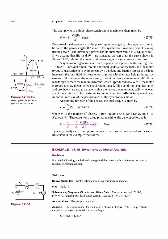
868 Chapter 17 Introduction to Electric Machines
The total power of a three-phase synchronous machine is then given by
P = (3)|VS ||Eb|
XS
sin(δ) (17.70)
Because of the dependence of the power upon the angle δ, this angle has come tobe called the power angle. If δ is zero, the synchronous machine cannot developuseful power. The developed power has its maximum value at δ equal to 90.If we assume that |Eb| and |VS | are constant, we can draw the curve shown inFigure 17.35, relating the power and power angle in a synchronous machine.
P
Pmax
δ < 0
δ > 0
–180°180°
–90°δ
Generator
Motor
–Pmax
Pmax = 3 Vs Eb
XS
90°
Figure 17.35 Powerversus power angle for asynchronous machine
A synchronous generator is usually operated at a power angle varying from15 to 25. For synchronous motors and small loads, δ is close to 0, and the motortorque is just sufficient to overcome its own windage and friction losses; as the loadincreases, the rotor field falls further out of phase with the stator field (although thetwo are still rotating at the same speed), until δ reaches a maximum at 90. If theload torque exceeds the maximum torque, which is produced for δ = 90, the motoris forced to slow down below synchronous speed. This condition is undesirable,and provisions are usually made to shut the motor down automatically wheneversynchronism is lost. The maximum torque is called the pull-out torque and is animportant measure of the performance of the synchronous motor.
Accounting for each of the phases, the total torque is given by
T = m
ωs
|VS ||IS | cos(θ) (17.71)
where m is the number of phases. From Figure 17.34, we have Eb sin(δ) =XSIS cos(θ). Therefore, for a three-phase machine, the developed torque is
T = P
ωs
= 3
ωs
|VS ||Eb|XS
sin(δ) N-m (17.72)
Typically, analysis of multiphase motors is performed on a per-phase basis, asillustrated in the examples that follow.
EXAMPLE 17.10 Synchronous Motor Analysis
Problem
Find the kVA rating, the induced voltage and the power angle of the rotor for a fullyloaded synchronous motor.
Is Rs
+
–
jXS
+
Eb ∠ –δ°∠ 0°
12 Ω1 Ω460
√3Vs =
Figure 17.36
Solution
Known Quantities: Motor ratings; motor synchronous impedance.
Find: S; Eb; δ.
Schematics, Diagrams, Circuits, and Given Data: Motor ratings: 460 V; 3 φ;pf = 0.707 lagging; full-load stator current: 12.5 A. ZS = 1 + j12 ..
Assumptions: Use per-phase analysis.
Analysis: The circuit model for the motor is shown in Figure 17.36. The per-phasecurrent in the wye-connected stator winding is
IS = |IS | = 12.5 A

Part III Electromechanics 869
The per-phase voltage is
VS = |VS | = 460 V√3
= 265.58 V
The kVA rating of the motor is expressed in terms of the apparent power, S (see Chapter 7):
S = 3VSIS = 3 × 265.58 V × 12.5 A = 9,959 W
From the equivalent circuit, we have
Eb = VS − IS(RS + jXS)
= 265.58 − (12.5∠ − 45 A) × (1 + j12 .) = 179.31∠ − 32.83 V
The induced line voltage is defined to be
Vline =√
3Eb =√
3 × 179.31 V = 310.57 V
From the expression for Eb, we can find the power angle:
δ = −32.83
Comments: The minus sign indicates that the machine is in the motor mode.
EXAMPLE 17.11 Synchronous Motor Analysis
Problem
Find the stator current, the line current and the induced voltage for a synchronous motor.
Solution
Known Quantities: Motor ratings; motor synchronous impedance.
Find: IS ; Iline; Eb.
Schematics, Diagrams, Circuits, and Given Data: Motor ratings: 208 V; 3 φ; 45 kVA;60 Hz; pf = 0.8 leading; ZS = 0 + j2.5 .. Friction and windage losses: 1.5 kW; corelosses: 1.0 kW. Load power: 15 hp.
Assumptions: Use per-phase analysis.
Analysis: The output power of the motor is 15 hp; that is:
Pout = 15 hp × 0.746 kW/hp = 11.19 kW
The electric power supplied to the machine is
Pin = Pout + Pmech + Pcore-loss + Pelec-loss
= 11.19 kW + 1.5 kW + 1.0 kW + 0 kW = 13.69kW
As discussed in Chapter 7, the resulting line current is
Iline = Pin√3V cos θ
= 13,690 W√3 × 208 V × 0.8
= 47.5 A
Because of the 5 connection, the armature current is
IS = 1√3
Iline = 27.4∠36.87 A

870 Chapter 17 Introduction to Electric Machines
The emf may be found from the equivalent circuit and KVL:
Eb = VS − jXSIS
= 208∠0 − j2.5 .(27.4∠36.87 A) = 255∠ − 12.4 V
The power angle is
δ = −12.4
Synchronous motors are not very commonly used in practice, for variousreasons, among which are that they are essentially required to operate at constantspeed (unless a variable-frequency AC supply is available) and that they are notself-starting. Further, separate AC and DC supplies are required. It will be seenshortly that the induction motor overcomes most of these drawbacks.
Check Your Understanding17.11 A synchronous generator has a multipolar construction that permits changingits synchronous speed. If only two poles are energized, at 50 Hz, the speed is 3,000 rev/min.If the number of poles is progressively increased to 4, 6, 8, 10, and 12, find the synchronousspeed for each configuration.
17.12 Draw the complete equivalent circuit of a synchronous generator and its phasordiagram.
17.13 Find an expression for the maximum pull-out torque of the synchronous motor.
17.8 THE INDUCTION MOTOR
The induction motor is the most widely used electric machine, because of itsrelative simplicity of construction. The stator winding of an induction machineis similar to that of a synchronous machine; thus, the description of the three-phase winding of Figure 17.25 also applies to induction machines. The primaryadvantage of the induction machine, which is almost exclusively used as a motor(its performance as a generator is not very good), is that no separate excitation isrequired for the rotor. The rotor typically consists of one of two arrangements:a squirrel cage, or a wound rotor. The former contains conducting bars short-circuited at the end and embedded within it; the latter consists of a multiphasewinding similar to that used for the stator, but electrically short-circuited.
In either case, the induction motor operates by virtue of currents inducedfrom the stator field in the rotor. In this respect, its operation is similar to that ofa transformer, in that currents in the stator (which acts as a primary coil) inducecurrents in the rotor (acting as a secondary coil). In most induction motors, noexternal electrical connection is required for the rotor, thus permitting a simple,rugged construction, without the need for slip rings or brushes. Unlike the syn-chronous motor, the induction motor does not operate at synchronous speed, but ata somewhat lower speed, which is dependent on the load. Figure 17.37 illustratesthe appearance of a squirrel-cage induction motor. The following discussion willfocus mainly on this very common configuration.

Part III Electromechanics 871
N SBS
S
→
BR→
Shortedconductors
Shortedconductors
Shorting rings on end
(a) (b) (c)
(d)
∆vm,
N
Figure 17.37 (a) Squirrel-cage induction motor; (b) conductors in rotor; (c) photo of squirrel-cage induction motor;(d) views of Smokin’ Buckey motor: rotor, stator, and cross section of stator (Courtesy: David H. Koether Photography.)
You are by now acquainted with the notion of a rotating stator magneticfield. Imagine now that a squirrel-cage rotor is inserted in a stator in which sucha rotating magnetic field is present. The stator field will induce voltages in thecage conductors, and if the stator field is generated by a three-phase source, theresulting rotor currents—which circulate in the bars of the squirrel cage, with theconducting path completed by the shorting rings at the end of the cage—are alsothree-phase, and are determined by the magnitude of the induced voltages and bythe impedance of the rotor. Since the rotor currents are induced by the stator field,the number of poles and the speed of rotation of the induced magnetic field are thesame as those of the stator field, if the rotor is at rest. Thus, when a stator field isinitially applied, the rotor field is synchronous with it, and the fields are stationarywith respect to each other. Thus, according to the earlier discussion, a startingtorque is generated.
If the starting torque is sufficient to cause the rotor to start spinning, therotor will accelerate up to its operating speed. However, an induction motor cannever reach synchronous speed; if it did, the rotor would appear to be stationarywith respect to the rotating stator field, since it would be rotating at the samespeed. But in the absence of relative motion between the stator and rotor fields,no voltage would be induced in the rotor. Thus, an induction motor is limited tospeeds somewhere below the synchronous speed, ns . Let the speed of rotation of
872 Chapter 17 Introduction to Electric Machines
the rotor be n; then, the rotor is losing ground with respect to the rotation of thestator field at a speed (ns − n). In effect, this is equivalent to backward motion ofthe rotor at the slip speed, defined by (ns − n). The slip, s, is usually defined asa fraction of ns :
s = ns − n
ns(17.73)
which leads to the following expression for the rotor speed:
n = ns(1 − s) (17.74)
The slip, s, is a function of the load, and the amount of slip in a given motoris dependent on its construction and rotor type (squirrel cage or wound rotor).Since there is a relative motion between the stator and rotor fields, voltages will beinduced in the rotor at a frequency called the slip frequency, related to the relativespeed of the two fields. This gives rise to an interesting phenomenon: the rotorfield travels relative to the rotor at the slip speed sns , but the rotor is mechanicallytraveling at the speed (1 − s)ns , so that the net effect is that the rotor field travelsat the speed
sns + (1 − s)ns = ns (17.75)
that is, at synchronous speed. The fact that the rotor field rotates at synchronousspeed—although the rotor itself does not—is extremely important, because itmeans that the stator and rotor fields will continue to be stationary with respect toeach other, and therefore a net torque can be produced.
As in the case of DC and synchronous motors, important characteristics ofinduction motors are the starting torque, the maximum torque, and the torque-speed curve. These will be discussed shortly, after some analysis of the inductionmotor is performed in the next few paragraphs.
EXAMPLE 17.12 Induction Motor Analysis
Problem
Find the full load rotor slip and frequency of the induced voltage at rated speed in afour-pole induction motor.
Solution
Known Quantities: Motor ratings.
Find: s; fR .
Schematics, Diagrams, Circuits, and Given Data: Motor ratings: 230 V; 60 Hz;full-load speed: 1,725 rev/min.
Analysis: The synchronous speed of the motor is
ns = 120f
p= 60f
p/2= 60 s/min × 60 rev/s
4/2= 1,800 rev/min
The slip is
s = ns − n
ns= 1,800 rev/min − 1,725 rev/min
1,800 rev/min= 0.0417

Part III Electromechanics 873
The rotor frequency, fR , is
fR = sf = 0.0417 × 60 Hz = 2.5 Hz
The induction motor can be described by means of an equivalent circuit,which is essentially that of a rotating transformer. (See Chapter 16 for a circuitmodel of the transformer.) Figure 17.38 depicts such a circuit model, where:
RS = stator resistance per phase, RR = rotor resistance per phase
XS = stator reactance per phase, XR = rotor reactance per phase
Xm = magnetizing (mutual) reactance
RC = equivalent core-loss resistance
ES = per-phase induced voltage in stator windings
ER = per-phase induced voltage in rotor windings
The primary internal stator voltage, ES , is coupled to the secondary rotor voltage,ER , by an ideal transformer with an effective turns ratio α. For the rotor circuit,the induced voltage at any slip will be
ER = sER0 (17.76)
where ER0 is the induced rotor voltage at the condition in which the rotor isstationary. Also, XR = ωRLR = 2πfRLR = 2πsfLR = sXR0, where XR0 =2πfLR is the reactance when the rotor is stationary. The rotor current is given bythe expression
IR = ER
RR + jXR
= sER0
RR + jsXR0= ER0
RR/s + jXR0(17.77)
The resulting rotor equivalent circuit is shown in Figure 17.39.
IS RS jXS jXRIR
VS RC jXm ES ER
+
–
Ideal transformer
RR
+
–
α
Figure 17.38 Circuit model for induction machine
+
–
IR
ER0
jXR0RRS
Figure 17.39 Rotor circuit
The voltages, currents, and impedances on the secondary (rotor) side can bereflected to the primary (stator) by means of the effective turns ratio. When thistransformation is effected, the transformed rotor voltage is given by
E2 = E′R = αER0 (17.78)
The transformed (reflected) rotor current is
I2 = IRα
(17.79)

874 Chapter 17 Introduction to Electric Machines
The transformed rotor resistance can be defined as
R2 = α2RR (17.80)
and the transformed rotor reactance can be defined by
X2 = α2XR0 (17.81)
The final per-phase equivalent circuit of the induction motor is shown in Figure17.40.
IS RS
VS RC jXm
+
–
jX2
R2
ES = E2
jXS
I2
S
Figure 17.40 Equivalent circuit of aninduction machine
The following examples illustrate the use of the circuit model in determiningthe performance of the induction motor.
EXAMPLE 17.13 Induction Motor Analysis
Problem
Determine the following quantities for an induction motor using the circuit model ofFigures 17.38 to 17.40.
1. Speed
2. Stator current
3. Power factor
4. Output torque
Solution
Known Quantities: Motor ratings; circuit parameters.
Find: n; ωm; IS ; pf; T .
Schematics, Diagrams, Circuits, and Given Data: Motor ratings: 460 V; 60 Hz; fourpoles; s = 0.022; P = 14 hpRS = 0.641 .; R2 = 0.332 .; XS = 1.106 .; XS = 0.464 .; Xm = 26.3 .
Assumptions: Use per-phase analysis. Neglect core losses (RC = 0).

Part III Electromechanics 875
Analysis:
1. The per-phase equivalent circuit is shown in Figure 17.40. The synchronous speed isfound to be
ns = 120f
p= 60 s/min × 60 rev/s
4/2= 1,800 rev/min
or
ωs = 1,800 rev/min × 2π rad
60 s/min= 188.5 rad/s
The rotor mechanical speed is
n = (1 − s)ns rev/min = 1,760 rev/min
or
ωm = (1 − s)ωs rad/s = 184.4 rad/s
2. The reflected rotor impedance is found from the parameters of the per-phase circuit tobe
Z2 = R2
s+ jX2 = 0.332
0.022+ j0.464 .
= 15.09 + j0.464 .
The combined magnetization plus rotor impedance is therefore equal to
Z = 1
1/jXm + 1/Z2= 1
−j0.038 + 0.0662∠ − 1.76 = 12.94∠31.1 .
and the total impedance is
Ztotal = ZS + Z = 0.641 + j1.106 + 11.08 + j6.68
= 11.72 + j7.79 = 14.07∠33.6 .
Finally, the stator current is given by
IS = VS
Ztotal= 460/
√3∠0 V
14.07∠33.6 .= 18.88∠ − 33.6 A
3. The power factor is
pf = cos 33.6 = 0.883 lagging
4. The output power, Pout, is
Pout = 14 hp × 746 W/hp = 10.444 kW
and the output torque is
T = Pout
ωm
= 10,444 W
184.4 rad/s= 56.64 N-m
EXAMPLE 17.14 Induction Motor Analysis
Problem
Determine the following quantities for a three-phase induction motor using the circuitmodel of Figures 17.39 to 17.41.
1. Stator current

876 Chapter 17 Introduction to Electric Machines
I1 RS XS X2 I2R2s
Im IR
Xm RCVS
–
+
Figure 17.41
2. Power factor
3. Full-load electromagnetic torque
Solution
Known Quantities: Motor ratings; circuit parameters.
Find: IS ; pf; T .
Schematics, Diagrams, Circuits, and Given Data: Motor ratings: 500 V; 3 φ; 50 Hz;p = 8; s = 0.05; P = 14 hp.Circuit parameters: RS = 0.13 .; R′
R = 0.32 .; XS = 0.6 .; X′R = 1.48 .;
Ym = GC + jBm = magnetic branch admittance describing core loss and mutualinductance = 0.004 − j0.05 .−1; stator to rotor turns ratio = 1 : α = 1 : 1.57.
Assumptions: Use per-phase analysis. Neglect mechanical losses.
Analysis: The approximate equivalent circuit of the three-phase induction motor on aper-phase basis is shown in Figure 17.41. The parameters of the model are calculated asfollows:
R2 = R′R ×
(1
α
)2
= 0.32 ×(
1
1.57
)2
= 0.13 .
X2 = X′R ×
(1
α
)2
= 1.48 ×(
1
1.57
)2
= 0.6 .
Z = RS + R2
S+ j (XS + X2)
= 0.13 + 0.13
0.05+ j (0.6 + 0.6) = 2.73 + j1.2 .
Using the approximate circuit,
I2 = VS
Z= (500/
√3)∠0 V
2.73 + j1.2 .= 88.8 − j39 A
IR = VSGS = 288.7 V × 0.004 .−1 = 1.15 A
Im = −jVSBm = 288.7 V × (−j0.05). = −j14.4 A
I1 = I2 + IR + Im = 89.95 − j53.4 A
Input power factor = Re[I1]
|I1| = 89.95
104.6= 0.86 lagging
Torque = 3P
ωS
= 3I 22R2/s
4πf/p= 935 N-m
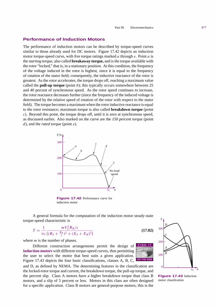
Part III Electromechanics 877
Performance of Induction Motors
The performance of induction motors can be described by torque-speed curvessimilar to those already used for DC motors. Figure 17.42 depicts an inductionmotor torque-speed curve, with five torque ratings marked a through e. Point a isthe starting torque, also called breakaway torque, and is the torque available withthe rotor “ locked,” that is, in a stationary position. At this condition, the frequencyof the voltage induced in the rotor is highest, since it is equal to the frequencyof rotation of the stator field; consequently, the inductive reactance of the rotor isgreatest. As the rotor accelerates, the torque drops off, reaching a maximum valuecalled the pull-up torque (point b); this typically occurs somewhere between 25and 40 percent of synchronous speed. As the rotor speed continues to increase,the rotor reactance decreases further (since the frequency of the induced voltage isdetermined by the relative speed of rotation of the rotor with respect to the statorfield). The torque becomes a maximum when the rotor inductive reactance is equalto the rotor resistance; maximum torque is also called breakdown torque (pointc). Beyond this point, the torque drops off, until it is zero at synchronous speed,as discussed earlier. Also marked on the curve are the 150 percent torque (pointd), and the rated torque (point e).
T,%
300
200
100
0
a
b
cd
e
No-loadspeed
ns n
Figure 17.42 Performance curve forinduction motor
A general formula for the computation of the induction motor steady-statetorque-speed characteristic is
T = 1
ωe
mV 2S RR/s
[(RS + RR
s)2 + (XS + XR)2]
(17.82)
where m is the number of phases.
T
D
C
A
B
300
200
100
0nns
Figure 17.43 Inductionmotor classification
Different construction arrangements permit the design ofinduction motors with different torque-speed curves, thus permittingthe user to select the motor that best suits a given application.Figure 17.43 depicts the four basic classifications, classes A, B, C,and D, as defined by NEMA. The determining features in the classification arethe locked-rotor torque and current, the breakdown torque, the pull-up torque, andthe percent slip. Class A motors have a higher breakdown torque than class Bmotors, and a slip of 5 percent or less. Motors in this class are often designedfor a specific application. Class B motors are general-purpose motors; this is the

878 Chapter 17 Introduction to Electric Machines
most commonly used type of induction motor, with typical values of slip of 3 to5 percent. Class C motors have a high starting torque for a given starting current,and a low slip. These motors are typically used in applications demanding highstarting torque but having relatively normal running loads, once running speed hasbeen reached. Class D motors are characterized by high starting torque, high slip,low starting current, and low full-load speed. A typical value of slip is around 13percent.
Factors that should be considered in the selection of an AC motor for a givenapplication are the speed range, both minimum and maximum, and the speedvariation. For example, it is important to determine whether constant speed isrequired; what variation might be allowed, either in speed or in torque; or whethervariable-speed operation is required, in which case a variable-speed drive willbe needed. The torque requirements are obviously important as well. The start-ing and running torque should be considered; they depend on the type of load.Starting torque can vary from a small percentage of full-load to several timesfull-load torque. Furthermore, the excess torque available at start-up determinesthe acceleration characteristics of the motor. Similarly, deceleration charac-teristics should be considered, to determine whether external braking might berequired.
Another factor to be considered is the duty cycle of the motor. The duty cycle,which depends on the nature of the application, is an important consideration whenthe motor is used in repetitive, noncontinuous operation, such as is encounteredin some types of machine tools. If the motor operates at zero or reduced load forperiods of time, the duty cycle—that is, the percentage of the time the motor isloaded—is an important selection criterion. Last, but by no means least, are theheating properties of a motor. Motor temperature is determined by internal lossesand by ventilation; motors operating at a reduced speed may not generate sufficientcooling, and forced ventilation may be required.
Thus far, we have not considered the dynamic characteristics of inductionmotors. Among the integral-horsepower induction motors (i.e., motors with horse-power rating greater than one), the most common dynamic problems are associatedwith starting and stopping and with the ability of the motor to continue operationduring supply system transient disturbances. Dynamic analysis methods for in-duction motors depend to a considerable extent on the nature and complexityof the problem and the associated precision requirements. When the electricaltransients in the motor are to be included as well as the motional transients, andespecially when the motor is an important element in a large network, the simpletransient equivalent circuit of Figure 17.44 provides a good starting approxima-tion. In the circuit model of Figure 17.44, X′
S is called the transient reactance.The voltage E′
S is called the voltage behind the transient reactance and is as-sumed to be equal to the initial value of the induced voltage, at the start of thetransient. RS is the stator resistance. The dynamic analysis problem consists ofselecting a sufficiently simple but reasonably realistic representation that will notunduly complicate the dynamic analysis, particularly through the introduction ofnonlinearities.
+
–
RSX'S
ES'VS
+
–
Figure 17.44 Simplifiedinduction motor dynamic model
It should be remarked that the basic equations of the induction machine,as derived from first principles, are quite nonlinear. Thus, an accurate dynamicanalysis of the induction motor, without any linearizing approximations, requiresthe use of computer simulation.
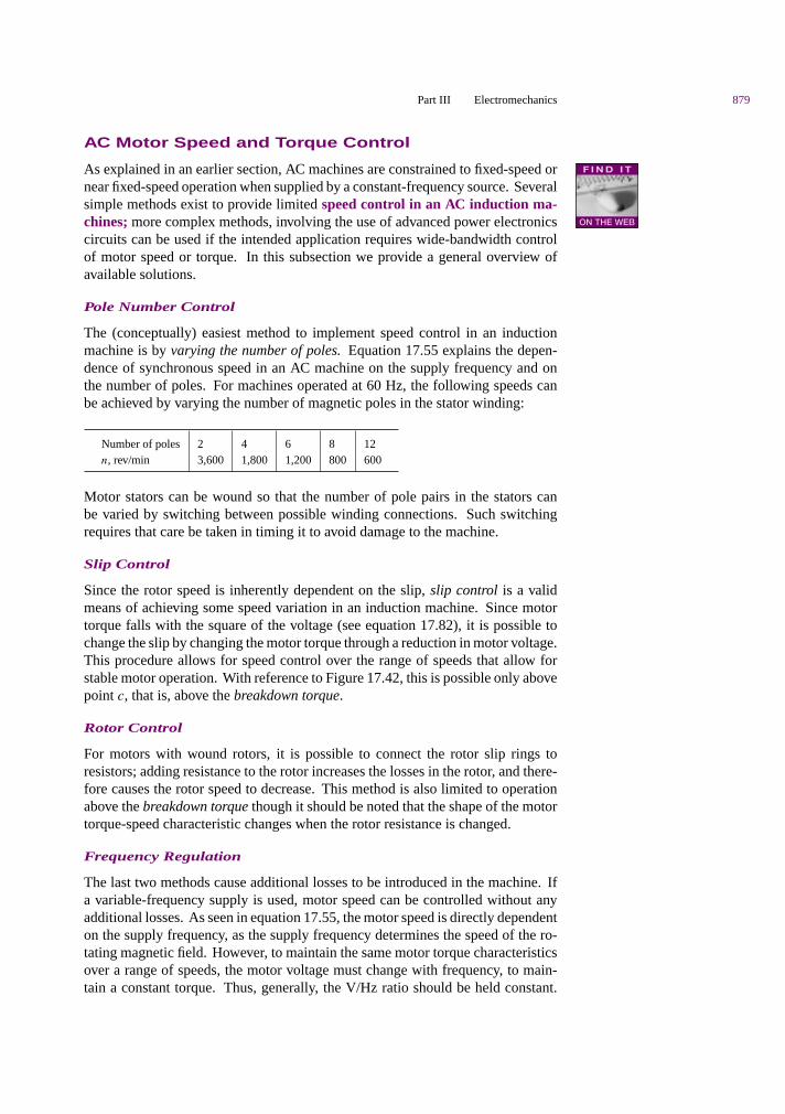
Part III Electromechanics 879
AC Motor Speed and Torque Control
As explained in an earlier section, AC machines are constrained to fixed-speed ornear fixed-speed operation when supplied by a constant-frequency source. Severalsimple methods exist to provide limited speed control in an AC induction ma-chines; more complex methods, involving the use of advanced power electronicscircuits can be used if the intended application requires wide-bandwidth controlof motor speed or torque. In this subsection we provide a general overview ofavailable solutions.
Pole Number Control
The (conceptually) easiest method to implement speed control in an inductionmachine is by varying the number of poles. Equation 17.55 explains the depen-dence of synchronous speed in an AC machine on the supply frequency and onthe number of poles. For machines operated at 60 Hz, the following speeds canbe achieved by varying the number of magnetic poles in the stator winding:
Number of poles 2 4 6 8 12n, rev/min 3,600 1,800 1,200 800 600
Motor stators can be wound so that the number of pole pairs in the stators canbe varied by switching between possible winding connections. Such switchingrequires that care be taken in timing it to avoid damage to the machine.
Slip Control
Since the rotor speed is inherently dependent on the slip, slip control is a validmeans of achieving some speed variation in an induction machine. Since motortorque falls with the square of the voltage (see equation 17.82), it is possible tochange the slip by changing the motor torque through a reduction in motor voltage.This procedure allows for speed control over the range of speeds that allow forstable motor operation. With reference to Figure 17.42, this is possible only abovepoint c, that is, above the breakdown torque.
Rotor Control
For motors with wound rotors, it is possible to connect the rotor slip rings toresistors; adding resistance to the rotor increases the losses in the rotor, and there-fore causes the rotor speed to decrease. This method is also limited to operationabove the breakdown torque though it should be noted that the shape of the motortorque-speed characteristic changes when the rotor resistance is changed.
Frequency Regulation
The last two methods cause additional losses to be introduced in the machine. Ifa variable-frequency supply is used, motor speed can be controlled without anyadditional losses. As seen in equation 17.55, the motor speed is directly dependenton the supply frequency, as the supply frequency determines the speed of the ro-tating magnetic field. However, to maintain the same motor torque characteristicsover a range of speeds, the motor voltage must change with frequency, to main-tain a constant torque. Thus, generally, the V/Hz ratio should be held constant.

880 Chapter 17 Introduction to Electric Machines
This condition is difficult to achieve at start-up and at very low frequencies, inwhich cases the voltage must be raised above the constant V/Hz ratio that will beappropriate at higher frequency.
Adjustable-Frequency Drives
The advances made in the last two decades in power electronics and microcon-trollers (see Chapters 11 and 14) have made AC machines employing adjustable-frequency drives well-suited to many common engineering applications that un-til recently required the use of the more easily speed-controlled DC drives. Anadjustable-frequency drive consists of four major subsystems, as shown in Figure17.45.
Intermediatecircuit
Control and regulation circuit
Rectifier~~~
Inverter Motor
Figure 17.45 General configuration of adjustable-frequency drive
The diagram of Figure 17.45 assumes that a three-phase AC supply is avail-able; the three-phase AC voltage is rectified using a controlled or uncontrolledrectifier (see Chapter 8 for a description of uncontrolled rectifiers and Chapter 11for a description of controlled rectifiers). An intermediate circuit is sometimesnecessary to further condition the rectified voltage and current. An inverter is thenused to convert the fixed DC voltage to a variable frequency and variable ampli-tude AC voltage. This is accomplished via pulse-amplitude modulation (PAM)or increasingly, via pulse-width modulation (PWM) techniques. Figure 17.46
(a) (c) (e)
VVI
Vol
tage
Cur
rent
s
CSI PWM
(b) (d) (f)
Figure 17.46 Typical adjustable-frequency controller voltageand current waveforms. (Courtesy: Rockwell Automation, RelianceElectric)

Part III Electromechanics 881
illustrates how approximately sinusoidal currents and voltages of variable fre-quency can be obtained by suitable shaping a train of pulses. It is important tounderstand that the technology used to generate such wave shapes is based onthe simple power switching concepts underlying the voltage-source inverter (VSI)drive described in Chapter 11. DC-AC inverters come in many different configu-rations; the interested reader will find additional information and resources in theaccompanying CD-ROM.
Check Your Understanding17.14 A three-phase induction motor has six poles. (a) If the line frequency is60 Hz, calculate the speed of the magnetic field in rev/min. (b) Repeat the calculationif the frequency is changed to 50 Hz.
17.15 A four-pole induction motor operating at a frequency of 60 Hz has a full-loadslip of 4 percent. Find the frequency of the voltage induced in the rotor (a) at the instant ofstarting and (b) at full load.
17.16 A four-pole, 1,746-rev/min, 220-V, 3-phase, 60-Hz, 10-hp, Y-connected induc-tion machine has the following parameters: RS = 0.4 ., R2 = 0.14 ., Xm = 16 .,XS = 0.35 ., X2 = 0.35 ., RC = 0. Using Figure 16.39, find: (a) the stator current;(b) the rotor current; (c) the motor power factor; and (d) the total stator power input.
CONCLUSION
The principles developed in Chapter 17 can be applied to rotating electric machines, toexplain how mechanical energy can be converted to electrical energy, and vice versa. Theformer function is performed by electric generators, while the latter is provided by electricmotors.
• Electric machines are described in terms of their mechanical characteristics, theirtorque-speed curves, and their electrical characteristics, including current andvoltage requirements. Losses and efficiency are an important part of the operationof electric machines, and it should be recognized that there will be electricallosses (due to the resistance of the windings), mechanical losses (friction andwindage), and magnetic core losses (eddy currents, hysteresis). The mainmechanical components of an electric machine are the stator, rotor, and air gap.Electrically, the important parameters are the armature (load current-carrying)circuit, and the field (magnetizing) circuit. Magnetic fields establish the couplingbetween the electrical and mechanical systems.
• Electric machines are broadly classified into DC and AC machines; the formeruse DC excitation for both the field and armature circuits, while the latter may befurther subdivided into two classes: synchronous machines, and induction motors.AC synchronous machines are characterized by DC field and AC armatureexcitation. Induction machines (of the squirrel-cage type), on the other hand, donot require a field excitation, since this is provided by electromagnetic induction.Typically, DC machines have the armature winding on the rotor, while ACmachines have it on the stator.
• The performance of electric machines can be approximately predicted with theuse of circuit models, or of performance curves. The selection of a particularmachine for a given application is driven by many factors, including theavailability of suitable electrical supplies (or prime movers), the type of load, andvarious other concerns, of which heat dissipation and thermal characteristics areprobably the most important.
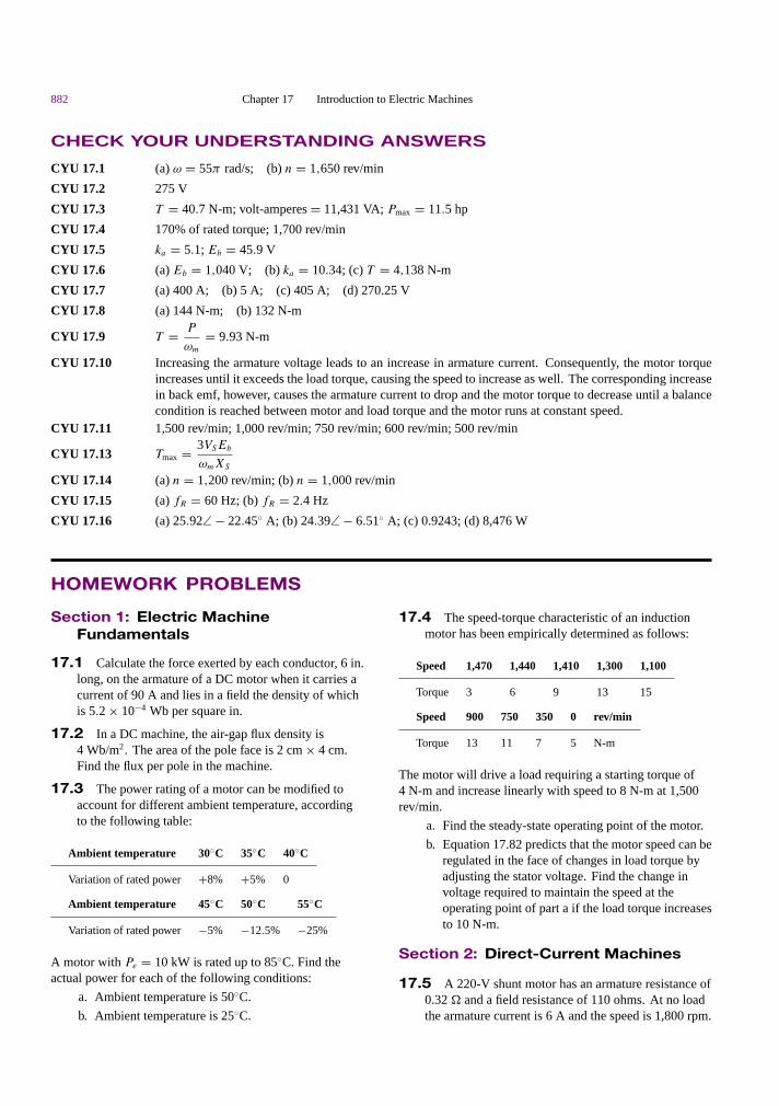
882 Chapter 17 Introduction to Electric Machines
CHECK YOUR UNDERSTANDING ANSWERS
CYU 17.1 (a) ω = 55π rad/s; (b) n = 1,650 rev/min
CYU 17.2 275 V
CYU 17.3 T = 40.7 N-m; volt-amperes = 11,431 VA; Pmax = 11.5 hp
CYU 17.4 170% of rated torque; 1,700 rev/min
CYU 17.5 ka = 5.1; Eb = 45.9 V
CYU 17.6 (a) Eb = 1,040 V; (b) ka = 10.34; (c) T = 4,138 N-m
CYU 17.7 (a) 400 A; (b) 5 A; (c) 405 A; (d) 270.25 V
CYU 17.8 (a) 144 N-m; (b) 132 N-m
CYU 17.9 T = P
ωm
= 9.93 N-m
CYU 17.10 Increasing the armature voltage leads to an increase in armature current. Consequently, the motor torqueincreases until it exceeds the load torque, causing the speed to increase as well. The corresponding increasein back emf, however, causes the armature current to drop and the motor torque to decrease until a balancecondition is reached between motor and load torque and the motor runs at constant speed.
CYU 17.11 1,500 rev/min; 1,000 rev/min; 750 rev/min; 600 rev/min; 500 rev/min
CYU 17.13 Tmax = 3VSEb
ωmXS
CYU 17.14 (a) n = 1,200 rev/min; (b) n = 1,000 rev/min
CYU 17.15 (a) fR = 60 Hz; (b) fR = 2.4 Hz
CYU 17.16 (a) 25.92∠ − 22.45 A; (b) 24.39∠ − 6.51 A; (c) 0.9243; (d) 8,476 W
HOMEWORK PROBLEMS
Section 1: Electric MachineFundamentals
17.1 Calculate the force exerted by each conductor, 6 in.long, on the armature of a DC motor when it carries acurrent of 90 A and lies in a field the density of whichis 5.2 × 10⁻⁴ Wb per square in.
17.2 In a DC machine, the air-gap flux density is4 Wb/m2. The area of the pole face is 2 cm × 4 cm.Find the flux per pole in the machine.
17.3 The power rating of a motor can be modified toaccount for different ambient temperature, accordingto the following table:
Ambient temperature 30C 35C 40C
Variation of rated power +8% +5% 0
Ambient temperature 45C 50C 55C
Variation of rated power −5% −12.5% −25%
A motor with Pe = 10 kW is rated up to 85C. Find theactual power for each of the following conditions:
a. Ambient temperature is 50C.
b. Ambient temperature is 25C.
17.4 The speed-torque characteristic of an inductionmotor has been empirically determined as follows:
Speed 1,470 1,440 1,410 1,300 1,100
Torque 3 6 9 13 15
Speed 900 750 350 0 rev/min
Torque 13 11 7 5 N-m
The motor will drive a load requiring a starting torque of4 N-m and increase linearly with speed to 8 N-m at 1,500rev/min.
a. Find the steady-state operating point of the motor.
b. Equation 17.82 predicts that the motor speed can beregulated in the face of changes in load torque byadjusting the stator voltage. Find the change involtage required to maintain the speed at theoperating point of part a if the load torque increasesto 10 N-m.
Section 2: Direct-Current Machines
17.5 A 220-V shunt motor has an armature resistance of0.32 . and a field resistance of 110 ohms. At no loadthe armature current is 6 A and the speed is 1,800 rpm.

Part III Electromechanics 883
Assume that the flux does not vary with load andcalculate:
a. The speed of the motor when the line current is62 A (assume a 2-volt brush drop).
b. The speed regulation of the motor.
17.6 A 120-V, 10-A shunt generator has an armatureresistance of 0.6 .. The shunt field current is 2 A.Determine the voltage regulation of the generator.
17.7 A 50-hp, 550-volt shunt motor has an armatureresistance, including brushes, of 0.36 ohm. Whenoperating at rated load and speed, the armature takes75 amp. What resistance should be inserted in thearmature circuit to obtain a 20 percent speed reductionwhen the motor is developing 70 percent of ratedtorque? Assume that there is no flux change.
17.8 A 20-kW, 230-V separately excited generator hasan armature resistance of 0.2 . and a load current of100 A. Find:
a. The generated voltage when the terminal voltage is230 V.
b. The output power.
17.9 A 10-kW, 120-VDC series generator has anarmature resistance of 0.1 . and a series fieldresistance of 0.05 .. Assuming that it is deliveringrated current at rated speed, find (a) the armaturecurrent and (b) the generated voltage.
17.10 The armature resistance of a 30-kW, 440-V shuntgenerator is 0.1 .. Its shunt field resistance is 200 ..Find
a. The power developed at rated load.
b. The load, field, and armature currents.
c. The electrical power loss.
17.11 A four-pole, 450-kW, 4.6-kV shunt generator hasarmature and field resistances of 2 and 333 .. Thegenerator is operating at the rated speed of3,600 rev/min. Find the no-load voltage of thegenerator and terminal voltage at half load.
17.12 A shunt DC motor has a shunt field resistance of400 . and an armature resistance of 0.2 .. The motornameplate rating values are 440 V, 1,200 rev/min,100 hp, and full-load efficiency of 90 percent. Find:
a. The motor line current.
b. The field and armature currents.
c. The counter emf at rated speed.
d. The output torque.
17.13 A 30-kW, 240-V generator is running at half loadat 1,800 rev/min with efficiency of 85 percent. Findthe total losses and input power.
17.14 A 240-volt series motor has an armatureresistance of 0.42 . and a series-field resistance of
0.18 .. If the speed is 500 rev/min when the current is36 A, what will be the motor speed when the loadreduces the line current to 21 A? (Assume a 3-voltbrush drop and that the flux is proportional to thecurrent.)
17.15 A 220-VDC shunt motor has an armatureresistance of 0.2 . and a rated armature current of50 A. Find
a. The voltage generated in the armature.
b. The power developed.
17.16 A 550-volt series motor takes 112 A and operatesat 820 rev/min when the load is 75 hp. If the effectivearmature-circuit resistance is 0.15 ., calculate thehorsepower output of the motor when the current dropsto 84 A, assuming that the flux is reduced by 15percent.
17.17 A 200-VDC shunt motor has the followingparameters:
Ra = 0.1 . Rf = 100 .
When running at 1,100 rev/min with no load connectedto the shaft, the motor draws 4 A from the line. Find E
and the rotational losses at 1,100 rev/min (assumingthat the stray-load losses can be neglected).
17.18 A 230-VDC shunt motor has the followingparameters:
Ra = 0.5 . Rf = 75 .
Prot = 500 W (at 1,120 rev/min)
When loaded, the motor draws 46 A from the line.Find
a. The speed, Pdev, and Tsh.
b. If Lf = 25 H, La = 0.008 H, and the terminalvoltage has a 115-V change, find ia(t) and ωm(t).
17.19 A 200-VDC shunt motor with an armatureresistance of 0.1 . and a field resistance of 100 .
draws a line current of 5 A when running with no loadat 955 rev/min. Determine the motor speed, the motorefficiency, the total losses (i.e., rotational and I 2R
losses), and the load torque (i.e., Tsh) that will resultwhen the motor draws 40 A from the line. Assumerotational power losses are proportional to the squareof shaft speed.
17.20 A self-excited DC shunt generator is delivering20 A to a 100-V line when it is driven at 200 rad/s. Themagnetization characteristic is shown inFigure P17.20. It is known that Ra = 1.0 . andRf = 100 .. When the generator is disconnectedfrom the line, the drive motor speeds up to 220 rad/s.What is the terminal voltage?

884 Chapter 17 Introduction to Electric Machines
180
120
60
0.5 1.0 1.5 2.0 If Amps
EbVolts
ω = 200 rad/sec
Figure P17.20
17.21 A 50-hp, 230-volt shunt motor has a fieldresistance of 17.7 . and operates at full load when theline current is 181 A at 1,350 rev/min. To increase thespeed of the motor to 1,600 rev/min, a resistance of5.3 . is “cut in” via the field rheostat; the line currentthen increases to 190 A. Calculate:
a. The power loss in the field and its percentage of thetotal power input for the 1,350 rev/min speed.
b. The power losses in the field and the field rheostatfor the 1,600 rev/min speed.
c. The percent losses in the field and in the fieldrheostat at 1,600 rev/min.
17.22 A 10-hp, 230-volt shunt-wound motor has ratedspeed of 1,000 rev/min and full-load efficiency of 86percent. Armature circuit resistance is 0.26 .;field-circuit resistance is 225 .. If this motor isoperating under rated load and the field flux is veryquickly reduced to 50 percent of its normal value, whatwill be the effect upon counter emf, armature currentand torque? What effect will this change have upon theoperation of the motor, and what will be its speedwhen stable operating conditions have been regained?
17.23 The machine of example 17.7 is being used in aseries connection. That is, the field coil is connected inseries with the armature, as shown in Figure P17.23.The machine is to be operated under the sameconditions as in the previous example, that is, n =120 rev/min, Ia = 8 A. In the operating region,φ = kIf , and k = 200. The armature resistance is 0.2., and the resistance of the field winding is negligible.
a. Find the number of field winding turns necessaryfor full-load operation.
b. Find the torque output for the following speeds:
1. n′ = 2n 3. n′ = n/2
2. n′ = 3n 4. n′ = n/4
c. Plot the speed-torque characteristic for theconditions of part b.
ia Rf Ra
VS Eb
+
–
Figure P17.23
17.24 With reference to Example 17.9, assume that theload torque applied to the PM DC motor is zero.Determine the response of the motor to a step changein input voltage. Derive expressions for the naturalfrequency and damping ratio of the second ordersystem. What determines whether the system is over-or underdamped?
17.25 A motor with polar moment of inertia J developstorque according to the relationship T = aω + b. Themotor drives a load defined by the torque-speedrelationship TL = cω2 + d. If the four coefficients areall positive constants, determine the equilibriumspeeds of the motor-load pair, and whether thesespeeds are stable.
17.26 Assume that a motor has known friction andwindage losses described by the equation TFW = bω.Sketch the T -ω characteristic of the motor if the loadtorque, TL, is constant, and the TL-ω characteristic ifthe motor torque is constant. Assume that TFW at fullspeed is equal to 30 percent of the load torque.
17.27 A PM DC motor is rated at 6 V, 3350 rev/min,and has the following parameters: ra = 7 ., La =120 mH, kT = 7 × 10⁻³ N-m/A, J = 1 × 10⁻⁶ kg-m2.The no-load armature current is 0.15 A.
a. In the steady-state no-load condition, the magnetictorque must be balanced by an internal dampingtorque; find the damping coefficient, b. Now sketcha model of the motor, write the dynamic equations,and determine the transfer function from armaturevoltage to motor speed. What is the approximate3-dB bandwidth of the motor?
b. Now let the motor be connected to a pump withinertia JL = 1 × 10⁻⁴ kg-m2, damping coefficientbL = 5 × 10⁻³ N-m-s, and load torqueTL = 3.5 × 1−−3 N-m. Sketch the modeldescribing the motor-load configuration, and writethe dynamic equations for this system; determinethe new transfer function from armature voltage tomotor speed. What is the approximate 3-dBbandwidth of the motor/pump system?
17.28 A PM DC motor with torque constant kPM is usedto power a hydraulic pump; the pump is a positivedisplacement type and generates a flow proportional tothe pump velocity: qp = kpω. The fluid travels
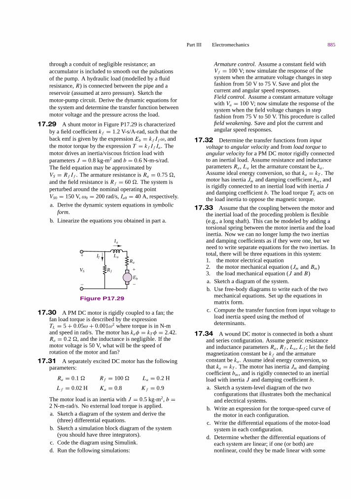
Part III Electromechanics 885
through a conduit of negligible resistance; anaccumulator is included to smooth out the pulsationsof the pump. A hydraulic load (modelled by a fluidresistance, R) is connected between the pipe and areservoir (assumed at zero pressure). Sketch themotor-pump circuit. Derive the dynamic equations forthe system and determine the transfer function betweenmotor voltage and the pressure across the load.
17.29 A shunt motor in Figure P17.29 is characterizedby a field coefficient kf = 1.2 V-s/A-rad, such that theback emf is given by the expression Eb = kf If ω, andthe motor torque by the expression T = kf If Ia . Themotor drives an inertia/viscous friction load withparameters J = 0.8 kg-m2 and b = 0.6 N-m-s/rad.The field equation may be approximated byVS = Rf If . The armature resistance is Ra = 0.75 .,and the field resistance is Rf = 60 .. The system isperturbed around the nominal operating pointVS0 = 150 V, ω0 = 200 rad/s, Ia0 = 40 A, respectively.
a. Derive the dynamic system equations in symbolicform.
b. Linearize the equations you obtained in part a.
VS R f
If La
Ia
Ra
Eb
+
–
+
–
Figure P17.29
17.30 A PM DC motor is rigidly coupled to a fan; thefan load torque is described by the expressionTL = 5 + 0.05ω + 0.001ω2 where torque is in N-mand speed in rad/s. The motor has kaφ = kT φ = 2.42.Ra = 0.2 ., and the inductance is negligible. If themotor voltage is 50 V, what will be the speed ofrotation of the motor and fan?
17.31 A separately excited DC motor has the followingparameters:
Ra = 0.1 . Rf = 100 . La = 0.2 H
Lf = 0.02 H Ka = 0.8 Kf = 0.9
The motor load is an inertia with J = 0.5 kg-m2, b =2 N-m-rad/s. No external load torque is applied.a. Sketch a diagram of the system and derive the
(three) differential equations.b. Sketch a simulation block diagram of the system
(you should have three integrators).c. Code the diagram using Simulink.d. Run the following simulations:
Armature control. Assume a constant field withVf = 100 V; now simulate the response of thesystem when the armature voltage changes in stepfashion from 50 V to 75 V. Save and plot thecurrent and angular speed responses.Field control. Assume a constant armature voltagewith Va = 100 V; now simulate the response of thesystem when the field voltage changes in stepfashion from 75 V to 50 V. This procedure is calledfield weakening. Save and plot the current andangular speed responses.
17.32 Determine the transfer functions from inputvoltage to angular velocity and from load torque toangular velocity for a PM DC motor rigidly connectedto an inertial load. Assume resistance and inductanceparameters Ra , La let the armature constant be ka .Assume ideal energy conversion, so that ka = kT . Themotor has inertia Jm and damping coefficient bm, andis rigidly connected to an inertial load with inertia Jand damping coefficient b. The load torque TL acts onthe load inertia to oppose the magnetic torque.
17.33 Assume that the coupling between the motor andthe inertial load of the proceding problem is flexible(e.g., a long shaft). This can be modeled by adding atorsional spring between the motor inertia and the loadinertia. Now we can no longer lump the two inertiasand damping coefficients as if they were one, but weneed to write separate equations for the two inertias. Intotal, there will be three equations in this system:1. the motor electrical equation2. the motor mechanical equation (Jm and Bm)3. the load mechanical equation (J and B)a. Sketch a diagram of the system.b. Use free-body diagrams to write each of the two
mechanical equations. Set up the equations inmatrix form.
c. Compute the transfer function from input voltage toload inertia speed using the method ofdeterminants.
17.34 A wound DC motor is connected in both a shuntand series configuration. Assume generic resistanceand inductance parameters Ra , Rf , La , Lf ; let the fieldmagnetization constant be kf and the armatureconstant be ka . Assume ideal energy conversion, sothat ka = kT . The motor has inertia Jm and dampingcoefficient bm, and is rigidly connected to an inertialload with inertia J and damping coefficient b.a. Sketch a system-level diagram of the two
configurations that illustrates both the mechanicaland electrical systems.
b. Write an expression for the torque-speed curve ofthe motor in each configuration.
c. Write the differential equations of the motor-loadsystem in each configuration.
d. Determine whether the differential equations ofeach system are linear; if one (or both) arenonlinear, could they be made linear with some
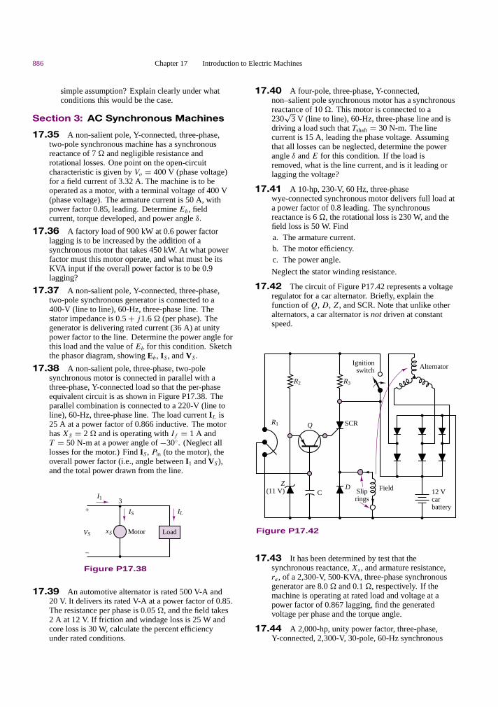
886 Chapter 17 Introduction to Electric Machines
simple assumption? Explain clearly under whatconditions this would be the case.
Section 3: AC Synchronous Machines
17.35 A non-salient pole, Y-connected, three-phase,two-pole synchronous machine has a synchronousreactance of 7 . and negligible resistance androtational losses. One point on the open-circuitcharacteristic is given by Vo = 400 V (phase voltage)for a field current of 3.32 A. The machine is to beoperated as a motor, with a terminal voltage of 400 V(phase voltage). The armature current is 50 A, withpower factor 0.85, leading. Determine Eb, fieldcurrent, torque developed, and power angle δ.
17.36 A factory load of 900 kW at 0.6 power factorlagging is to be increased by the addition of asynchronous motor that takes 450 kW. At what powerfactor must this motor operate, and what must be itsKVA input if the overall power factor is to be 0.9lagging?
17.37 A non-salient pole, Y-connected, three-phase,two-pole synchronous generator is connected to a400-V (line to line), 60-Hz, three-phase line. Thestator impedance is 0.5 + j1.6 . (per phase). Thegenerator is delivering rated current (36 A) at unitypower factor to the line. Determine the power angle forthis load and the value of Eb for this condition. Sketchthe phasor diagram, showing Eb, IS , and VS .
17.38 A non-salient pole, three-phase, two-polesynchronous motor is connected in parallel with athree-phase, Y-connected load so that the per-phaseequivalent circuit is as shown in Figure P17.38. Theparallel combination is connected to a 220-V (line toline), 60-Hz, three-phase line. The load current IL is25 A at a power factor of 0.866 inductive. The motorhas XS = 2 . and is operating with If = 1 A andT = 50 N-m at a power angle of −30. (Neglect alllosses for the motor.) Find IS , Pin (to the motor), theoverall power factor (i.e., angle between I1 and VS),and the total power drawn from the line.
I1
xS
IS IL
VS
+
–
Motor Load
3
Figure P17.38
17.39 An automotive alternator is rated 500 V-A and20 V. It delivers its rated V-A at a power factor of 0.85.The resistance per phase is 0.05 ., and the field takes2 A at 12 V. If friction and windage loss is 25 W andcore loss is 30 W, calculate the percent efficiencyunder rated conditions.
17.40 A four-pole, three-phase, Y-connected,non–salient pole synchronous motor has a synchronousreactance of 10 .. This motor is connected to a230
√3 V (line to line), 60-Hz, three-phase line and is
driving a load such that Tshaft = 30 N-m. The linecurrent is 15 A, leading the phase voltage. Assumingthat all losses can be neglected, determine the powerangle δ and E for this condition. If the load isremoved, what is the line current, and is it leading orlagging the voltage?
17.41 A 10-hp, 230-V, 60 Hz, three-phasewye-connected synchronous motor delivers full load ata power factor of 0.8 leading. The synchronousreactance is 6 ., the rotational loss is 230 W, and thefield loss is 50 W. Finda. The armature current.b. The motor efficiency.c. The power angle.
Neglect the stator winding resistance.
17.42 The circuit of Figure P17.42 represents a voltageregulator for a car alternator. Briefly, explain thefunction of Q, D, Z, and SCR. Note that unlike otheralternators, a car alternator is not driven at constantspeed.
D
R2 R3
Q
Z(11 V) C Slip
rings
Ignitionswitch Alternator
Field 12 Vcar battery
R1 SCR
Figure P17.42
17.43 It has been determined by test that thesynchronous reactance, Xs , and armature resistance,ra , of a 2,300-V, 500-KVA, three-phase synchronousgenerator are 8.0 . and 0.1 ., respectively. If themachine is operating at rated load and voltage at apower factor of 0.867 lagging, find the generatedvoltage per phase and the torque angle.
17.44 A 2,000-hp, unity power factor, three-phase,Y-connected, 2,300-V, 30-pole, 60-Hz synchronous
Part III Electromechanics 887
motor has a synchronous reactance of 1.95 . perphase. Neglect all losses. Find the maximum powerand torque.
17.45 A 1,200-V, three-phase, wye-connectedsynchronous motor takes 110 kW (exclusive of fieldwinding loss) when operated under a certain load at1,200 rev/min. The back emf of the motor is 2,000 V.The synchronous reactance is 10 . per phase, withnegligible winding resistance. Find the line currentand the torque developed by the motor.
17.46 The per-phase impedance of a 600-V,three-phase, Y-connected synchronous motor is5 + j50 .. The motor takes 24 kW at a leading powerfactor of 0.707. Determine the induced voltage and thepower angle of the motor.
Section 4: AC Induction Machines
17.47 A 74.6-kW, three-phase, 440-V (line to line),four-pole, 60-Hz induction motor has the following(per-phase) parameters referred to the stator circuit:
RS = 0.06 . XS = 0.3 . Xm = 5 .
RR = 0.08 . XR = 0.3 .
The no-load power input is 3,240 W at a current of 45A. Determine the line current, the input power, thedeveloped torque, the shaft torque, and the efficiency ats = 0.02.
17.48 A 60-Hz, four-pole, Y-connected induction motoris connected to a 400-V (line to line), three-phase,60-Hz line. The equivalent circuit parameters are:
RS = 0.2 . RR = 0.1 .
XS = 0.5 . XR = 0.2 .
Xm = 20 .
When the machine is running at 1,755 rev/min, the totalrotational and stray-load losses are 800 W. Determinethe slip, input current, total input power, mechanicalpower developed, shaft torque, and efficiency.
17.49 A three-phase, 60-Hz induction motor has eightpoles and operates with a slip of 0.05 for a certain load.Determinea. The speed of the rotor with respect to the stator.b. The speed of the rotor with respect to the stator
magnetic field.c. The speed of the rotor magnetic field with respect
to the rotor.d. The speed of the rotor magnetic field with respect
to the stator magnetic field.
17.50 A three-phase, two-pole, 400-V (per phase),60-Hz induction motor develops 37 kW (total) ofmechanical power (Pm) at a certain speed. Therotational loss at this speed is 800 W (total).(Stray-load loss is negligible.)
a. If the total power transferred to the rotor is 40 kW,determine the slip and the output torque.
b. If the total power into the motor (Pin) is 45 kW andRS is 0.5 . find IS and the power factor.
17.51 The nameplate speed of a 25-Hz induction motoris 720 rev/min. If the speed at no load is 745 rev/min,calculate:a. The slipb. The percent regulation
17.52 The name plate of a squirrel-cage four-poleinduction motor has the following information: 25 hp,220 volts, three-phase, 60 Hz, 830 rev/min, 64A linecurrent. If the motor draws 20,800 watts whenoperating at full load, calculate:a. Slipb. Percent regulation if the no-load speed is 895 rpmc. Power factord. Torquee. Efficiency
17.53 A 60-Hz, four-pole, Y-connected induction motoris connected to a 200-V (line to line), three-phase,60 Hz line. The equivalent circuit parameters are:
RS = 0.48 . Rotational loss torque = 3.5 N-m
XS = 0.8 . RR = 0.42 . (referred to the stator)
Xm = 30 . XR = 0.8 . (referred to the stator)
The motor is operating at slip s = 0.04. Determine theinput current, input power, mechanical power, andshaft torque (assuming that stray-load losses arenegligible).
17.54a. A three-phase, 220-V, 60-Hz induction motor runs
at 1,140 rev/min. Determine the number of poles(for minimum slip), the slip, and the frequency ofthe rotor currents.
b. To reduce the starting current, a three-phasesquirrel-cage induction motor is started by reducingthe line voltage to Vs/2. By what factor are thestarting torque and the starting current reduced?
17.55 A six-pole induction motor for vehicle tractionhas a 50-kW rating and is 85 percent efficient. If thesupply is 220 V at 60 Hz, compute the motor speedand torque at a slip of 0.04.
17.56 An AC induction machine has six poles and isdesigned for 60-Hz, 240-V (rms) operation. When themachine operates with 10 percent slip, it produces60 N-m of torque.a. The machine is now used in conjunction with a
friction load which opposes a torque of 50 N-m.Determine the speed and slip of the machine whenused with the above mentioned load.
b. If the machine has an efficiency of 92 percent, whatminimum rms current is required for operation withthe load of part a)?

888 Chapter 17 Introduction to Electric Machines
[Hint: you may assume that the speed torque curve isapproximately linear in the region of interest.]
17.57 A blocked-rotor test was performed on a 5-hp,220-V, four-pole, 60 Hz, three-phase induction motor.The following data were obtained: V = 48 V, I =18 A, P = 610 W. Calculate:a. The equivalent stator resistance per phase, RS
b. The equivalent rotor resistance per phase, RR
c. The equivalent blocked-rotor reactance per phase,XR
17.58 Calculate the starting torque of the motor ofProblem 17.58 when it is started at:a. 220 Vb. 110 V
The starting torque equation is:
T = m
ωe
· V 2S · RR
(RR + RS)2 + (XR + XS)2
17.59 Find the speed of the rotating field of a six-pole,three-phase motor connected to (a) a 60-Hz line and(b) a 50-Hz line, in rev/min and rad/s.
17.60 A six-pole, three-phase, 440-V, 60-Hz induction
motor has the following model impedances:
RS = 0.8 . XS = 0.7 .
RR = 0.3 . XR = 0.7 .
Xm = 35 .
Calculate the input current and power factor of themotor for a speed of 1,200 rev/min.
17.61 An eight-pole, three-phase, 220-V, 60-Hzinduction motor has the following model impedances:
RS = 0.78 . XS = 0.56 . Xm = 32 .
RR = 0.28 . XR = 0.84 .
Find the input current and power factor of this motorfor s = 0.02.
17.62 A nameplate is given in Example 17.2. Find therated torque, rated volt amperes, and maximumcontinuous output power for this motor.
17.63 A 3-phase induction motor, at rated voltage andfrequency, has a starting torque of 140 percent and amaximum torque of 210 percent of full-load torque.Neglect stator resistance and rotational losses andassume constant rotor resistance. Determine:a. The slip at full load.b. The slip at maximum torque.c. The rotor current at starting as a percent of full-load
rotor current.