chapter 9: assigning element level condition states … · manual of bridge inspection 2014 page...
TRANSCRIPT
Manual of Bridge Inspection 2014
Page 157
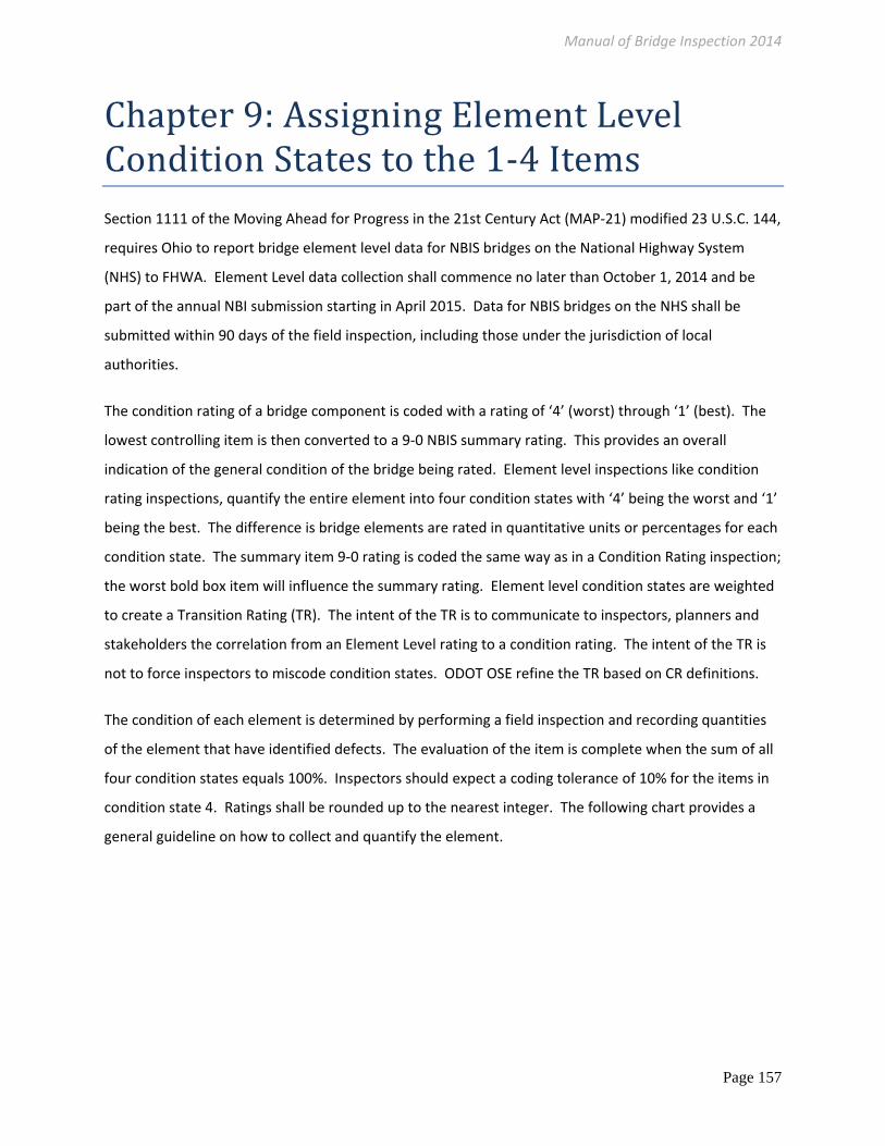
Chapter9:AssigningElementLevelConditionStatestothe1‐4ItemsSection 1111 of the Moving Ahead for Progress in the 21st Century Act (MAP‐21) modified 23 U.S.C. 144,
requires Ohio to report bridge element level data for NBIS bridges on the National Highway System
(NHS) to FHWA. Element Level data collection shall commence no later than October 1, 2014 and be
part of the annual NBI submission starting in April 2015. Data for NBIS bridges on the NHS shall be
submitted within 90 days of the field inspection, including those under the jurisdiction of local
authorities.
The condition rating of a bridge component is coded with a rating of ‘4’ (worst) through ‘1’ (best). The
lowest controlling item is then converted to a 9‐0 NBIS summary rating. This provides an overall
indication of the general condition of the bridge being rated. Element level inspections like condition
rating inspections, quantify the entire element into four condition states with ‘4’ being the worst and ‘1’
being the best. The difference is bridge elements are rated in quantitative units or percentages for each
condition state. The summary item 9‐0 rating is coded the same way as in a Condition Rating inspection;
the worst bold box item will influence the summary rating. Element level condition states are weighted
to create a Transition Rating (TR). The intent of the TR is to communicate to inspectors, planners and
stakeholders the correlation from an Element Level rating to a condition rating. The intent of the TR is
not to force inspectors to miscode condition states. ODOT OSE refine the TR based on CR definitions.
The condition of each element is determined by performing a field inspection and recording quantities
of the element that have identified defects. The evaluation of the item is complete when the sum of all
four condition states equals 100%. Inspectors should expect a coding tolerance of 10% for the items in
condition state 4. Ratings shall be rounded up to the nearest integer. The following chart provides a
general guideline on how to collect and quantify the element.

Manual of Bridge Inspection 2014
Page 158
Generic Item – Condition States (CS)
Defect GOOD
Condition State 1 FAIR
Condition State 2 POOR
Condition State 3 SEVERE
Condition State 4
Adjective Quantity that is
Good Quantity that is
Fair
Quantity that is Poor, does not
warrant a structural review
Warrants Structural Review OR the defect impacts the strength or serviceability of the
element
Maintenance Response ‐‐>
Monitor Protect Repair Rehab Replace
Monitor Protect Repair Rehab Replace
Monitor Protect Repair Rehab Replace
Monitor Protect Repair Rehab Replace
Table 64 ‐ Element Level Generic Rating
There are three major divisions of bridge elements:
National Bridge Elements (NBE) – Represent the primary structural components and are denoted in
the inspection report with bold black boxes, with the exception of bridge rail and bearings. The
NBE’s are a refinement of the Deck, Superstructure, Substructure and Culvert items from the FHWA
Recording and Coding Guide and are intended to be consistent nationwide.
Bridge Management Elements (BME) – Include components that are not bold boxes on the
inspection report and are typically managed in order to preserve and maintain bridges. Examples
include joints, wearing surfaces and protective coating systems.
Agency Developed Elements (ADE) – Include elements collected by ODOT that are important to the
current inspection program to maintain consistency and match legacy BR‐86 data. This information
does not get transferred to FHWA.
An inspector may find materials or guidelines that are not defined during the course of their inspection.
In these cases the inspector should use discretion and determine the appropriate condition. Surfaces or
element defects that are not visible for inspection shall be assessed based on the available visible
surface. Surfaces not visible shall be assessed
based on destructive and nondestructive testing
or indicators in the materials covering the
surfaces.
Severity: The worst portion of the 3‐Dimensional
elemental unit governs the entire quantity (ex.
Square footage is calculated using square areas,
Figure 72 – SF quantity

Manual of Bridge Inspection 2014
Page 159
linear footage of a beam includes a one foot section of both the web and flanges). Inspectors are given
the option to code either percentage (%) or Quantity.
Condition State 4 Warrants a structural review OR a Structural Review was performed and the defect
impacts strength or serviceability. This is reserved for critical conditions that are beyond the specific
defects defined in Condition States 1 through 3. Quantities in CS4 may often have implications that
affect public safety OR reduction in load capacity. If the inspector determines that there is an impact
on the load capacity or a direct impact on safety then the 4 is the appropriate rating. All Quantities in
CS4 must be accounted for with quantitative descriptions in the comments. Typical examples are given
in the charted guidelines but should
not limit the inspector.
Total Quantity
A good bridge database and a
functional bridge program are
entirely dependent on good bridge
inspection data. A bridge inspector
needs to be familiar with the
concept of breaking a bridge down
into its component elements and
assigning a condition state to each
element based mostly on visual
observations and plan information.
The quantities for the elements are
established and are categorized into
one of the three units: Area of
Square Feet (SF), Length or Linear
Feet (LF) or Count (EA).
The Bridge Inspection Field Report
has the Quantity cells highlighted.
Figure 74 ‐ Bridge Inspection Field Report Quantities

Manual of Bridge Inspection 2014
Page 160
APPROACH ITEMS Quantity Description
c1. Approach Wearing Surface (EA)
The quantity of this element is each Approach Wearing Surface immediately leading up to and off of the Approach Slab or, when no slab exists, up to and off of the bridge. Most structures will have 2 however divided highways with medians will have 4 when one bridge carries both directions.
c2. Slab (SF) The quantity of this element is the surface area of both approach slabs. Note the slabs often do not extend to the edge of pavement and inspectors must field verify or plan verify.
c3. Relief Joint (LF) The quantity of this element is the total length of the relief joints.
c4. Embankment (EA) ded
The quantity of this element is each embankment behind each wingwall, above the clear span of each inlet and outlet or each retaining wall supporting the approach slab and approach wearing surface.
c5. Guardrail (EA) The quantity of this element is each guardrail assembly on each corner (4) of the bridge.
Table 65 ‐ Approach Item Quantities
Figure 75 ‐ Approach Wearing Surface and Slab Quantities

Manual of Bridge Inspection 2014
Page 161
Figure 77 ‐ Quantity Example: Embankment 1 of 2
Figure 78 ‐ Culvert Embankment
Figure 76 ‐ Approach embankment 1 of 2
Approach Slab Approach Wearing Surface
2 Embankment
1 Embankment

Manual of Bridge Inspection 2014
Page 162
DECK ITEMS Quantity Description
c7.1 Floor/Slab (SF) The quantity of this element is the area of the deck/slab EXCLUDING deck edges including structures carrying divided highways. The area does account for any flares, gores or ramps present. Integral Floors (PSBB’s, T‐beams, Rigid Frames etc.) shall be rated and quantified in Square Feet in this item and in LINEAR FEET (LF) for Beams/Girders.
c7.2 Edge of Floor/Slab (LF) The quantity of this element is the two‐foot‐wide deck edges at each exposed fascia including divided highways. This element should not be rated for Prestressed Box Beams.
c8. Wearing Surface (SF) The quantity of this element is the area of the exposed surface of the wearing surface (from curb‐to‐curb, toe‐to‐toe or edge‐to‐edge) including paved shoulders and accounting for any flares, gores or ramps present.
c9. Curbs/Sidewalk (LF) The quantity of this element is the total length of all the curbs or all of the sidewalks on the bridge deck.
c10. Median (LF) The quantity of this element is the total length of the median on the bridge deck. For closed medians the quantity will be the overall structure length and for open medians the quantity will be twice the overall structure length to include both sides.
c11. Railing (LF) The quantity of this element is the total length of the railings on the bridge excluding median railings and additional pedestrian railing.
c12. Drainage (EA) ded The quantity of this element is the sum of each scupper/grating in the deck; for over‐the‐side or off‐the‐end drainage each side or end is equivalent to one (1).
c13. Expansion Joint (LF) ded Total linear feet of structural expansion joints.
Table 66 ‐ Deck Items Quantities
Figure 79 ‐ Quantity Example: Railing, Expansion Joint, Wearing Surface
Railing: LINEAR FEET (LF) 1 of 2
Railing: LINEAR FEET (LF) 2 of 2

Manual of Bridge Inspection 2014
Page 163
Figure 81 ‐ Quantity Example: Drainage
Drainage: EACH – (EA) – Four Scuppers shown
1
1
1
1
Figure 80 ‐ Quantity: Edge of Floor/Slab

Manual of Bridge Inspection 2014
Page 164
SUPERSTRUCTURE ITEMS Quantity Description
c14. Alignment (EA) ded The quantity of this element is the sum of all spans.
c15.1 Beams/Girders (LF) The quantity of this element is the sum of all longitudinal (excluding stringers) beam and girder lengths. Each linear foot includes the web and flanges.
C15.2 Slab (SF) The quantity of this element is for Slab‐Type Superstructures and is the area of the Slab EXCLUDING deck edges. The area does account for any flares, gores or ramps present.
c16. Diaphragm/X‐Frames (EA)
The quantity of this element is the sum of the number of diaphragms and cross frames.
c17. Stringers (LF) The quantity of this element is the sum of all of the lengths of each stringer. Each linear foot includes the web and flanges.
c18. Floorbeams (LF) The quantity of this element is the sum of all of the lengths of each floorbeam and includes cantilever sections. Each linear foot includes the web and flanges.
c19. Truss Verticals (EA) The quantity of this element is the sum of the number of truss vertical members. One member is from panel point to panel point
c20. Truss Diagonals (EA) The quantity of this element is the sum of the number of truss diagonal members. One member is from panel point to panel point.
c21. Truss Upper Chord (EA)
The quantity of this element is the sum of the number of truss upper chord members including end‐posts. One member is from panel point to panel point.
c22. Truss Lower Chord (EA)
EACH (EA) – The quantity of this element is the sum of the number of truss lower chord members. One member is from panel point to panel point.
c23. Truss Gusset Plate (EA) ded
The quantity of this element is the sum of each plate, two per panel point (interior/inboard and exterior/outboard); include gusset plates that intersect between chords or at midpoints.
c24. Lateral Bracing (EA) The quantity of this element is the sum of the number of upper lateral and lower lateral bracing members.
c25. Sway Bracing (EA) The quantity of this element is the sum of the number of sway and portal bracing struts. These general stabilize truss bridges and are attached between the left and right verticals and the left and right end‐posts.
c26. Bearing Devices (EA) ded
The quantity of this element is the sum of each movable and fixed bearing
c27. Arch (LF) The quantity of this element is the sum of all of the lengths of each arch panel measured longitudinal to the travel way and (not along the radius of the barrel or rib).
c28. Arch Column/Hanger (EA)
The quantity of this element is the sum of the number of arch columns or hangers. One member is from panel point to panel point.
c29. Arch Spandrel Walls (LF)
The quantity of this element is the sum of all of the lengths of each spandrel wall panel measured longitudinal to the travel way (not along the radius of the barrel or rib).

Manual of Bridge Inspection 2014
Page 165
SUPERSTRUCTURE ITEMS Quantity Description
c30. Prot. Coating System (LF) ded
Protective Coating System: LINEAR FEET (LF) – The quantity of this element is the total linear feet of all primary steel superstructure elements (ex. beams, girders, floorbeams, stringers). Steel truss lines and steel arch lines: the quantity is the sum of all truss panels measured along the roadway from bearing to bearing for each truss or arch‐line (often it is the length of the lowerchord) and any additional elements (ex. beams, girders, floorbeams, stringers).
c31. Pins/Hangers/Hinges (EA) ded
The quantity of this element is the sum of each hanger or hinge assembly.
c32. Fatigue (LF) ded The quantity of this element is the length of all primary steel members. See c30. Protective Coating System
Table 67 ‐ Superstructure Item Quantities
Figure 82 ‐ Quantity Example: Prestressed Box Beams
Beams/Girders: LINEAR FEET (LF)
Manual of Bridge Inspection 2014
Page 166
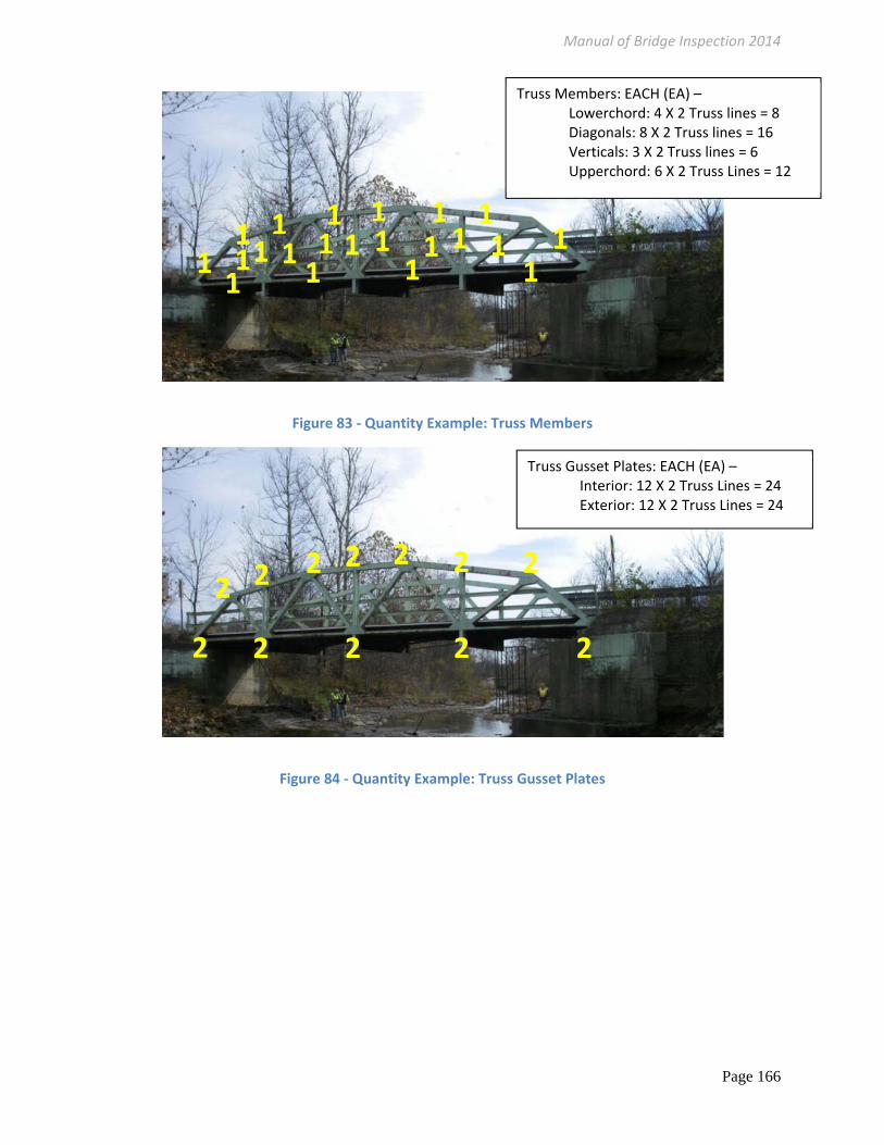
Figure 83 ‐ Quantity Example: Truss Members
Figure 84 ‐ Quantity Example: Truss Gusset Plates
Truss Members: EACH (EA) – Lowerchord: 4 X 2 Truss lines = 8 Diagonals: 8 X 2 Truss lines = 16 Verticals: 3 X 2 Truss lines = 6 Upperchord: 6 X 2 Truss Lines = 12
1 1 1 1 1 1 1
1 11 11
1 1
11 1
1 1 11
Truss Gusset Plates: EACH (EA) – Interior: 12 X 2 Truss Lines = 24 Exterior: 12 X 2 Truss Lines = 24
2
2
2 2 2 2
2 2 222 2

Manual of Bridge Inspection 2014
Page 167
Figure 85 ‐ Quantity Example: Crossframes, Steel Beams, PCS, Fatigue
Figure 86 ‐ Quantity Example: Pins/Hangers/Hinges
Diaphragm/Cross Frames: EACH (EA) – The quantity of this element is the sum of the number of diaphragms and cross frames. 35 shown
Pin/Hanger/Hinge – Each (EA): 1 hinge X 5 beam lines = 5

Manual of Bridge Inspection 2014
Page 168
Figure 87 ‐ Quantity Example: Arch and Spandrel Wall
Figure 88 ‐ Quantity Example: Floorbeams and Stringers
Arch and Arch Spandrel Walls: LINEAR FEET (LF) – The quantity of this element is the sum of all of the lengths of each spandrel wall panel measured longitudinal to the travel way (not along the radius of the barrel or rib). For filled arches there are two spandrel wall lengths (one on each side) and one arch length per span.
Floorbeams: LINEAR FEET (LF)

Manual of Bridge Inspection 2014
Page 169
Figure 89 ‐ Quantity Example: Stringers
Stringers: LINEAR FEET (LF)

Manual of Bridge Inspection 2014
Page 170
Protective Coating System: LINEAR FEET (LF) Truss Lines
1 Span = 168.9LF X 2 Truss Lines = 337.8 LF/Span 337.8 X 5 Spans = 1,689 LF Truss Lines
Stringers 10 Stringers/Bay X 14 LF = 140 LF 140LF X 9 Bays X 5 Spans = 6,300 LF Stringers
Floorbeams (including under sidewalk) 10 Floorbeams/Span X 40 LF/each = 400 LF 5 Spans X 400 LF/Span = 2,000 LF Floorbeam 1,689 LF Truss + 6,300 LF Stringer + 2,000 LF Floorbeam = 9,989 LF
Figure 90 ‐ Protective Coating System for Truss Bridges

Manual of Bridge Inspection 2014
Page 171
SUBSTRUCTURE ITEMS Quantity Description
c33. Abutment Walls (LF) The quantity of this element is the sum of the length (i.e. bridge width along the skew) of each Abutment Wall.
c34. Abutment Caps (LF) The quantity of this element is the sum of the length (i.e. bridge width along the skew) of each Abutment Cap.
c35. Abut. Colmns/Bents (EA)
The quantity of this element is the sum of all columns and bents at each Abutment.
c36. Pier Walls (LF) The quantity of this element is the sum of the length (i.e. bridge width along the skew) of each Pier Wall. For hammerhead piers the wall is the small bottom portion below the cap.
c37. Pier Caps (LF) The quantity of this element is the sum of the length (i.e. bridge width along the skew) of each Pier Cap.
c38. Pier Columns/Bents (EA)
The sum of the number of pier columns and bents.
c39. Backwalls (LF) The quantity of this element is the sum of the length (i.e. bridge width along the skew) of each Backwall.
c40. Wingwalls (EA) The quantity of this element is the sum of the length of each Wingwall
c42. Scour (EA) ded The quantity of this element is the sum of each substructure unit when a waterway exists underneath a structure.
c43. Slope Protection (EA) ded
This quantity is each protected slope underneath the superstructure
Table 68 ‐ Substructure Item Quantities
Figure 91 ‐ Quantity Example: Pier Caps, Pier Columns and Pier Walls
Pier Column – EACH (EA)
Pier Wall – Linear Feet (LF)
Pier Cap – Linear Feet (LF)

Manual of Bridge Inspection 2014
Page 172
Figure 92 ‐ Quantity Example: Pier Walls, Abutment Walls
Figure 93 ‐ Quantity Example: Pier Wall and Pier Cap
Pier Wall: LINEAR FEET (LF) Abutment Wall: LINEAR FEET (LF)
Pier Wall: LINEAR FEET (LF

Manual of Bridge Inspection 2014
Page 173
Figure 94 ‐ Quantity Example: Pier Bents, Scour
Figure 95 ‐ Quantity Example: Pier Columns
Pier Columns/Bents: EACH (EA) – 3 Span Continuous Slab 10 shown X 2 Piers = 20 Pier Bents Total
Scour: EACH (EA) – 3 Span Continuous Slab = 4
Pier Columns/Bents: EACH (EA) – 4 shown
1
11
1
1 1 1 1 1 1 1 1 11
Manual of Bridge Inspection 2014
Page 174
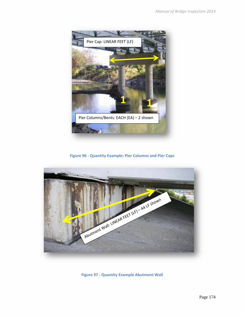
Figure 96 ‐ Quantity Example: Pier Columns and Pier Caps
Figure 97 ‐ Quantity Example Abutment Wall
1 1Pier Columns/Bents: EACH (EA) – 2 shown
Pier Cap: LINEAR FEET (LF)
Manual of Bridge Inspection 2014
Page 175
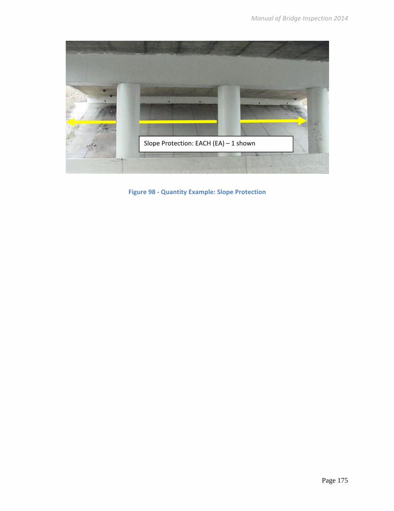
Figure 98 ‐ Quantity Example: Slope Protection
Slope Protection: EACH (EA) – 1 shown

Manual of Bridge Inspection 2014
Page 176
CULVERT ITEMS Quantity Description
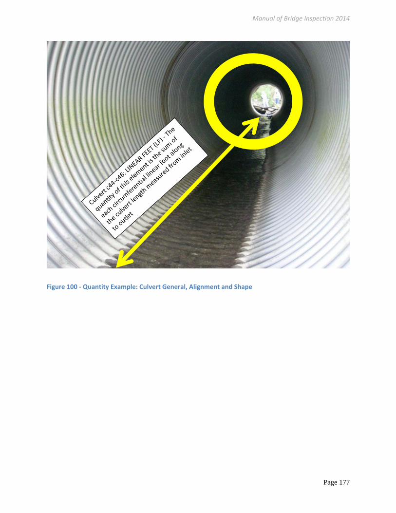
c44. General (LF) The quantity of this element is the sum of each circumferential linear foot along the culvert length measured from inlet to outlet
c45. Alignment (LF) ded See c.44 General
c46. Shape (LF) ded See c.44 General
c47. Seams (EA) ded The quantity of this element is each circumferential seam and each longitudinal (along the length of the conduit) seam. For multi‐plate corrugated metal pipes one longitudinal seam may be as long as the entire conduit.
c48. Headwall/Endwall (EA)
The quantity of this element is the sum of each headwall and endwall panel length measured longitudinal to the travel way
c49. Scour (EA) ded For closed‐cell conduits and four sided boxes the sum of each inlet and outlet opening. For conduits with open bottoms, three‐sided boxes and culverts with abutments the sum is each substructure unit, within each barrel or span.
c50. Abutment Walls (LF) LINEAR FEET (LF) – The quantity of this element is the sum of the width of each abutment wall.
Table 69 ‐ Culvert Item Quantities
Figure 99 ‐ Quantity Example: Scour
Scour: EACH (EA) – 4 shown
34
1 2
Manual of Bridge Inspection 2014
Page 177
Figure 100 ‐ Quantity Example: Culvert General, Alignment and Shape

Manual of Bridge Inspection 2014
Page 178
CHANNEL ITEMS Quantity Description
c51. Alignment (LF) ded The quantity of this element is the length from a point upstream to a point downstream based on what will affect the condition of the structure.
c52. Protection (LF) ded See c51.Alignment.
c53. Hydraulic Opening (EA) ded The quantity of this element is the sum of each Abutment and Pier or Conduit/Culvert when a waterway exists
c54. Navigation Lights (EA) ded The quantity of this element is the sum of each Navigation light
Table 70 ‐ Channel Item Quantities
Figure 101 ‐ Quantity Example: Hydraulic Opening
Hydraulic Opening (EA) ded EACH (EA) ‐ The quantity of this element is the sum of each Abutment and Pier or conduit when a waterway exists 3 Substructure Units Shown (2 Piers and 1 Abutment) 4 Total

Manual of Bridge Inspection 2014
Page 179
Figure 102 ‐ Quantity Example: Channel Alignment and Protection
Figure 103 ‐ Quantity Example: Channel Alignment and Protection
Channel Alignment and Protection: LINEAR FEET (LF) ‐ The quantity of this element is the upstream and downstream length of channel that influences the structure.
Channel Alignment and Protection: LINEAR FEET (LF) ‐ The quantity of this element is the upstream and downstream length of channel that influences the structure.

Manual of Bridge Inspection 2014
Page 180
SIGN/UTILITY ITEMS Quantity Description
c55. Signs (EA) ded The quantity of this element is the sum of each sign attached to the bridge or restriction or regulatory sign specific to the bridge (ex. advanced warning load posting, chevrons, vertical clearance).
c56. Sign Supports (EA) ded The quantity of this element is the sum of each attachment, on above or under the bridge, affixing the sign support to the bridge.
c57. Utilities (LF) ded The quantity of this element is the sum of each utility length attached to the bridge; including water, electrical, gas, sewer etc.
Table 71 ‐ Sign/Utilities Quantities
Figure 104 ‐ Quantity Example: Utilities
Utilities: LINEAR FEET (LF) ‐ The quantity of this element is the sum of each utility length attached to the bridge; including water, electrical, gas, sewer etc.

Manual of Bridge Inspection 2014
Page 181
Inspection Comments with Element Level
The rating an inspector assigns should be related to the actions required. All comments must be free of
hearsay and generalities outside of objective justification for the numerical ratings. All quantities in CS3
and CS4 must be communicated (comments, photos, sketches etc.) for the next inspector to find,
quantify, rate and determine obvious degradation. These comments must also account for and define
the predominant deficiency. Expect comments, photos, and documentation and inspection time to
increase as the structure degrades.
Field Report with Element Level
A completed Bridge Inspection Field
Report is a legal document. It may be
used by an inspector to complete either
an element level inspection or a
condition rating inspection. The
Quantities are populated from the
inventory items. Each bridge, at a
minimum, must be inspected in
accordance with the procedures in this
manual:
A qualified Team Leader is at the bridge at all times during each initial, routine, in‐depth,
fracture critical member and underwater inspection
Condition codes are correctly assigned
All notable bridge deficiencies are identified, and
Condition codes are supported by narrative, sketches or photos that appropriately justify and
document the rating assignment. Supportive documentation must be made available for the
next inspector.
The following Bridge Inspection Field Report has the Element Level Condition State Cells highlighted.
These cells shall be populated if the item exists on the structure, along with the NBIS items, when
completing an Element Level inspection. The Bridge Inspection Field Report is a document that may be
used to complete either an element level inspection or a condition rating inspection. The following
report has the Element Level Condition State boxes highlighted blue. All ratings in orange are required,
Figure 105 ‐ 1/8" Wide Crack in Concrete with 1/16" Offset

Manual of Bridge Inspection 2014
Page 182
when the item exists on the bridge, for both an element level and condition rating inspection. The
difference between Condition and Element Level is in coding the individual 1‐4 components.
Manual of Bridge Inspection 2014
Page 183
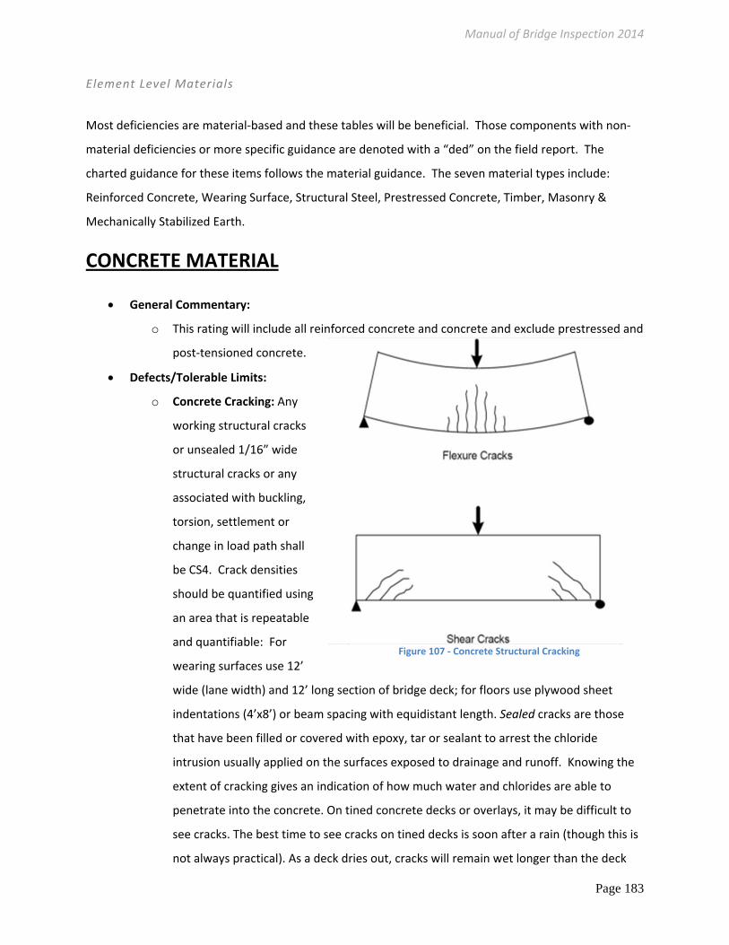
Figure 107 ‐ Concrete Structural Cracking
Element Level Materials
Most deficiencies are material‐based and these tables will be beneficial. Those components with non‐
material deficiencies or more specific guidance are denoted with a “ded” on the field report. The
charted guidance for these items follows the material guidance. The seven material types include:
Reinforced Concrete, Wearing Surface, Structural Steel, Prestressed Concrete, Timber, Masonry &
Mechanically Stabilized Earth.
CONCRETE MATERIAL
General Commentary:
o This rating will include all reinforced concrete and concrete and exclude prestressed and
post‐tensioned concrete.
Defects/Tolerable Limits:
o Concrete Cracking: Any
working structural cracks
or unsealed 1/16” wide
structural cracks or any
associated with buckling,
torsion, settlement or
change in load path shall
be CS4. Crack densities
should be quantified using
an area that is repeatable
and quantifiable: For
wearing surfaces use 12’
wide (lane width) and 12’ long section of bridge deck; for floors use plywood sheet
indentations (4’x8’) or beam spacing with equidistant length. Sealed cracks are those
that have been filled or covered with epoxy, tar or sealant to arrest the chloride
intrusion usually applied on the surfaces exposed to drainage and runoff. Knowing the
extent of cracking gives an indication of how much water and chlorides are able to
penetrate into the concrete. On tined concrete decks or overlays, it may be difficult to
see cracks. The best time to see cracks on tined decks is soon after a rain (though this is
not always practical). As a deck dries out, cracks will remain wet longer than the deck

Manual of Bridge Inspection 2014
Page 184
surface and thus appear as dark lines against
the lighter colored, dry deck. Consideration
may be used for raising a rating when a crack is
retrofitted or dormant. Structural cracks often
go through the entire member or tension zone
and are not superficial. Any one crack, no
matter how wide, may reduce the capacity of
the entire load path which would result in a
CS4 rating. It is up to the discretion of the
inspector to code concrete cracking correctly
based on location, orientation and activity (dormant or
‘working’). Types of cracks commonly encountered include
the following:
o Transverse flexural cracks (structural) due to bending will
most likely appear over the piers of continuous
superstructures (or positive bending or near mid‐span for
slabs).
o Shear Cracks (structural) will most likely be adjacent to supports.
o Longitudinal flexural cracks (structural). These are caused by negative bending of
the deck over the girders or beams or positive bending between girders or beams.
o Longitudinal reflective cracks (non‐structural) may appear along the joints of
adjacent prestressed box beams. This cracking is caused by differential beam
deflection.
o Radial cracks (non‐structural) at the acute corner of skewed bridge decks.
o Temperature and shrinkage cracks (non‐structural). These will be apparent on most
concrete.
o Transverse reflective cracks (non‐structural) may appear adjacent to an expansion
joint. These cracks suggest that the joint anchorage hardware is beginning to fail.
o Concrete Cracking References: According to the Unpublished Draft Guidelines for
NCHRP Project 12‐82,Developing Reliability‐Based Bridge Inspection Practices,
"engineering judgment [is] exercised in determining whether any present flexural
cracking is moderate to severe. Crack widths in reinforced concrete bridges exceeding
0.006 inches to 0.012 inches reflect the lower bound of moderate cracking. The
RC Crack Width
(in)
0.0125 1/8
0.090 3/32
0.080
0.070
0.060 1/16 Hairline
0.050
0.040
0.030 1/32
0.020
0.015 1/64

Manual of Bridge Inspection 2014
Page 185
American Concrete Institute Committee Report 224R‐01 presents guidance for what
could be considered reasonable or tolerable crack widths at the tensile face of
reinforced concrete structures for typical conditions. These range from 0.006 inches for
marine or seawater spray environments to 0.007 inches for structures exposed to de‐
icing chemicals, to 0.012 inches for structures in a humid, moist environment. The
location of crack is important. Deck cracking of 0.05” or greater may not be as
concerning as cracking of this magnitude in a reinforced concrete girder or beam.
Likewise a shrinkage crack 0.05” wide in a reinforced concrete girder that does not
move might be viewed differently than a 0.05” crack working under live load.
Concrete Spalls and Delaminations: Delamination or spalling of the concrete is not
necessarily an indication of poor concrete quality or of structural issues. It usually indicates
that chlorides and moisture have migrated through the concrete and attacked the
reinforcing steel. As the reinforcing steel corrodes, it increases in volume which tends to
push the concrete away from the steel. When the corrosion forces caused by this steel
expansion exceed the tensile strengths of the concrete, the concrete starts to delaminate or
separate from the surface. A hollow sounding surface when tapped with a hammer or steel
rod indicates a delamination which often results in a spall. The amount of time for this to
occur depends on the porosity or permeability of the concrete, the depth of resteel and the
prevalence of moisture and chlorides.
Settlement: Signs of continuing unrepaired settlement shall be coded CS3. Extreme
settlement or settlement that affects safety or load capacity shall be coded CS4. Any
quantity may be coded worse if the deficiency changed unexpectedly or rapidly.
Section Loss: Any 4 adjacent bars with 360 degree exposure OR any 4 adjacent bars with
more than 10% reduction in diameter will be CS4.
Scour: CS3 is Exposed vertical face of spread footing and CS4 is undermining. Deep
foundations CS3 is one or two exposed piling less than 1‐ft of the piling depth. CS4 is any
piling exposed more than 1‐ft. Any quantity may be coded worse if the deficiency changed
unexpectedly or rapidly.
Specific Elements:
Beam/Floor Separation: The area unseen above the top flange shall be downgraded when
evidence of movement and separation exists at the interface to CS2 and downgraded to CS3
when active movement under liveload is obvious.

Manual of Bridge Inspection 2014
Page 186
REINFORCED CONCRETE – Condition State Definitions (CS)Defect CS1 CS2 CS3 CS4
Delam/ Spall/ Patched Area
None
Delaminated. Spall 1 in. or less deep
OR 6 in. or less in
diameter. Patched area that is sound
Spall greater than 1 in. deep or greater than 6 in. diameter.
Patched area that is unsound or showing distress. Does not warrant structural review.
Safety: Requires immediate action to
ensure safety of public traffic
Serviceability: The condition is beyond the
limits established in condition state three (3), warrants a structural review to
determine the strength or serviceability
of the element or bridge, or
both
Exposed Rebar
None Present without measurable section
loss
Present with measurable section loss, but does not warrant a structural review
Cracking* Any sealed OR less than 0.012 in. wide or
spacing greater than 3.0 ft.
Unsealed Width 0.012‐0.05 in. or
spacing of 1.0‐3.0 ft.
Unsealed cracks greater than 0.05 in. wide or spacing of less
than 1 ft.
Efflorescence/ Rust Staining/ Saturated
None
Surface white without build‐up or leaching without rust staining. Arrested leaching or
saturation
Heavy build up. Rust staining
Abrasion/ Wear
None
Exposed coarse aggregate but the aggregate remains
secure in the concrete
Coarse aggregate is loose or has popped out of the concrete matrix due to abrasion or wear
Distortion None
Exists but does not require mitigation. Distortion that has been mitigated.
Distortion that requires mitigation that has not been addressed but does not
warrant a structural review.
Settlement None
Exists within tolerable limits or arrested with no observed structural
distress
Exceeds tolerable limits but does not warrant a structural
review.
Scour None
Exists within tolerable limits or has been
arrested with effective countermeasures
Exceeds tolerable limits but is less than the critical limits
determined by scour evaluation and does not warrant a
structural review.
Damage N/A Has impact but
repaired or minor Has impact but does not
warrant a structural review. Table 72 ‐ Element Level Material: Reinforced Concrete
*Cracking – the width and spacing dimensions represent 1) structural cracks OR 2) any crack that is in a corrosive environment. Inspector must use engineering judgment when nonstructural cracks are not exposed to corrosive chemicals, in other words inspectors should move the condition state ‘up’ or improve the rating. Working cracks or those likely reducing the capacity shall be CS4.

Manual of Bridge Inspection 2014
Page 187
WEARING SURFACE
General Commentary:
o This rating will include all wearing surfaces including asphalt and bituminous wearing
surfaces and relief joints.
o Inspector for sags, dips, impact and rideability.
Defects/Tolerable Limits:
o Crack density should be quantified using an area that is repeatable and quantifiable:
For wearing surfaces use 12’ wide (lane width) and 12’ long section of bridge deck.
o Effectiveness: CS4 When the WS is obviously not protecting the structural portions
underneath or the top surface is causing a rough ride, need to swerve or bounce for
vehicular traffic.
Specific Elements:
o Approach Wearing surface extends past the approach slab or, when no slab exists, past
the end of the bridge. The wearing course(s) on top of the approach slab shall be rated
within the approach slab element.
o Integral or Semi Integral: Pay careful attention to the transverse sections at the end of the
approach slab. Inspect for openings or distress from expansion.
Expansion Joint Header
Backwall
Expansion Joint Bridge Wearing Surface
Figure 108 ‐ Approach
Figure 109 – Wearing Surface CS4
Approach Slab
Manual of Bridge Inspection 2014
Page 188
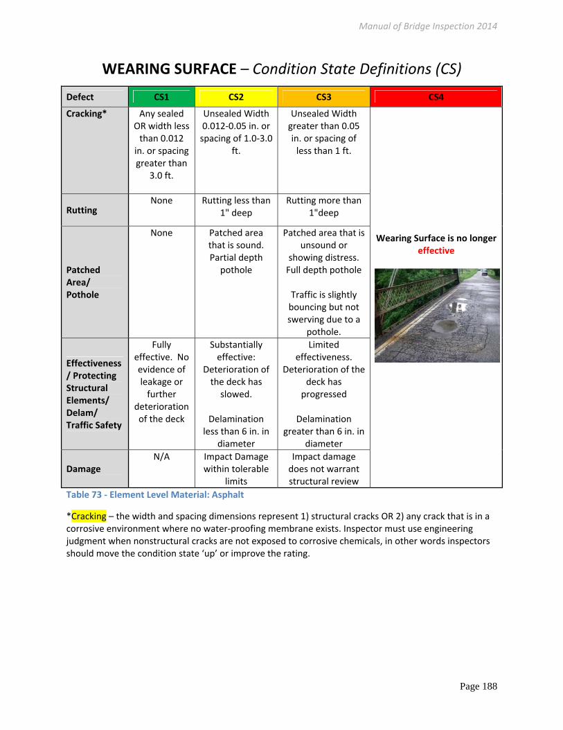
WEARING SURFACE – Condition State Definitions (CS)
Defect CS1 CS2 CS3 CS4
Cracking* Any sealed OR width less than 0.012 in. or spacing greater than
3.0 ft.
Unsealed Width 0.012‐0.05 in. or spacing of 1.0‐3.0
ft.
Unsealed Width greater than 0.05 in. or spacing of less than 1 ft.
Wearing Surface is no longer effective
Rutting None Rutting less than
1" deep Rutting more than
1"deep
Patched Area/ Pothole
None Patched area that is sound. Partial depth
pothole
Patched area that is unsound or
showing distress. Full depth pothole
Traffic is slightly bouncing but not swerving due to a
pothole.
Effectiveness / Protecting Structural Elements/ Delam/ Traffic Safety
Fully effective. No evidence of leakage or further
deterioration of the deck
Substantially effective:
Deterioration of the deck has slowed.
Delamination
less than 6 in. in diameter
Limited effectiveness.
Deterioration of the deck has progressed
Delamination
greater than 6 in. in diameter
Damage N/A Impact Damage
within tolerable limits
Impact damage does not warrant structural review
Table 73 ‐ Element Level Material: Asphalt
*Cracking – the width and spacing dimensions represent 1) structural cracks OR 2) any crack that is in a corrosive environment where no water‐proofing membrane exists. Inspector must use engineering judgment when nonstructural cracks are not exposed to corrosive chemicals, in other words inspectors should move the condition state ‘up’ or improve the rating.

Manual of Bridge Inspection 2014
Page 189
PRESTRESSED CONCRETE
o General Commentary:
o Defects/Tolerable Limits:
o Cracks in the concrete should be carefully measured and their location and length
documented. Any working structural cracks or unsealed 1/16” wide structural cracks or any
associated with buckling, torsion, settlement or change in load path.
Hairline ‐ 0.004"
Narrow ‐ 0.004"‐0.009"
Medium ‐ 0.010" ‐ 0.030"
Wide ‐ > 0.030”
o Strand Exposure– discount all strands visible AND those strands not visible located:
o Above a longitudinal cracks located in the bottom flange
o Above a delamination
o Above a spall with unsound or mottled concrete.
o Consideration should also be given to those strands neighboring and above a corroded
stirrup.
o Specific Elements:
Wide Longitudinal cracks in WS above combined with Strand exposure indicates independent beam
action which warrants a structural review.
Figure 111 ‐ PSBB Top Side Cracking Between Keys
Figure 112 ‐ PSBB underside, loss of strand capacity (same bridge)

Manual of Bridge Inspection 2014
Page 190
Prestressed Concrete – Condition State Definitions (CS)Defect CS1 CS2 CS3 CS4
Exposed* Prestressing
None One strand exposed*
Exposed strands* less than 25% of the beam width
Safety: Requires immediate action to ensure safety of public traffic
Serviceability: The condition is beyond the limits established in condition state
three (3), warrants a
structural review to determine the
strength or serviceability of the element or bridge, or both
Efflorescence/ Leaking Shear Keys (discount the QTY in both beams)
Dry or none
Light, evidence of leaking, no rust stains
Obvious active leaking, efflorescence buildup, or rust stains
Cracking
0‐0.004” Wide spaced more than 3 feet
0.004”‐0.009” wide or any spaced 1‐3 feet
no rust staining
Wider than 0.009”, or any spaced within 1‐foot, any
with rust staining
Movement None Minor misalignment but no movement under live load
Minor Independent Beam Movement under truck traffic only
Damage N/A Impact Damage within tolerable limits
Impact damage does not warrant structural review
Table 74 ‐ Element Level Material: Prestressed Concrete
*Exposed Prestressing– discount all strands visible AND those strands not visible located:
1) Above a longitudinal cracks located in the bottom flange
2) Above a delamination
3) Above a spall with unsound or saturated concrete.
4) Consideration should also be given to those strands neighboring and above a corroded stirrup.

Manual of Bridge Inspection 2014
Page 191
STEEL MATERIAL
This rating will include all elements that are metal.
o General Commentary:
o The worst portion of the 3‐dimensional element governs the quantity.
o Cracks in steel should be carefully measured and their location and length documented.
o Severity: Include the total linear feet of a component when a localized deficiency is severe
enough to affect the whole member at the discretion of the Team Leader.
o Defects/Tolerable Limits:
o Settlement: Dormant repaired settlement shall be CS2. Signs of continuing unrepaired
settlement shall be coded CS3. Extreme settlement that affects safety or load capacity shall
be coded CS4.
o Section Loss: CS4 is any corrosion hole or section loss more than 10% loss of the flange in
the tension zone or more than 10% loss in the web near the supports warrants a structural
review.
o Pack Rust: CS4 is Distortion is more than the plate thickness
o Cracking: CS4 is any crack in a FCM, any crack in the tension zone or
a crack generally longer than 2” in a compression zone.
o Settlement: Signs of continuing unrepaired settlement shall be
coded CS3. Extreme settlement or settlement that affects safety or
load capacity shall be coded CS4. Any quantity may be coded
worse if the deficiency changed unexpectedly or rapidly.
o Scour: CS4 is loss of bearing capacity
o Specific Elements:
o Bridge Railing: Include the total linear feet of bridge rail
supported by a post when the anchorage or support is
deficient, debonded or exposed.
o Crossframes/Diaphragms: for highly skewed or
horizontally curved bridges diaphragms and crossframes shall be considered primary bridge
elements.
o Pier Bents: Sheathed bents without a reinforcing cage shall follow the steel element level
chart. The bents with reinforcement shall be rated using the concrete element level chart.
Figure 113 ‐ corrosion holes
Figure 114 ‐ Steel CS4

Manual of Bridge Inspection 2014
Page 192
Steel – Condition States (CS) Defect CS1 CS2 CS3 CS4
Section loss None Minor, surface pitting, up to 1/16” at worst
Any pitting between 1/16” and 10% deep loss of section
Safety: Requires immediate action to ensure safety of public
traffic
Serviceability: The condition is beyond the limits established in
condition state three (3), warrants a structural
review to determine the strength or serviceability
of the element or bridge, or both Safety: Requires immediate
action to ensure safety of public traffic
Serviceability: The
condition is beyond the limits established in
condition state three (3), warrants a structural
review to determine the strength or serviceability
of the element or bridge, or both
Corrosion, Pack Rust/ Connection
None
Freckled rust. Corrosion has initiated. Pack rust without distortion.
Missing bolt, rivet, broken weld, fasteners or pack rust with distortion but does not warrant a structural review.
Cracking/ Fatigue
None Repaired or arrested* cracks
Any initiated or propagated crack in the compression zone that does not warrant structural review
Distortion None
Exists but does not require mitigation. Distortion that has been mitigated
Distortion that requires mitigation that has not been addressed but does not warrant a structural review
Settlement None
within tolerable limits or arrested with no observed structural distress
Exceeds tolerable limits does not warrant a structural review.
Scour None
Exists within tolerable limits or has been arrested with effective countermeasures
Exceeds tolerable limits but is less than the critical limits determined by scour evaluation and does not warrant a structural review.
Damage N/A Has impact but repaired or minor
Has impact but does not warrant a structural review.
Table 75 ‐ Element Level Material: Steel
*Arrested – self arrested, effective arrest holes or doubling plates o
Figure 115 ‐ CS 4 Axial Member Buckled

Manual of Bridge Inspection 2014
Page 193
TIMBER MATERIAL
This rating will include all elements that are timber.
General Commentary:
Defects/Tolerable Limits:
o Settlement: Signs of continuing unrepaired settlement shall be coded CS3. Extreme
settlement that affects safety or load capacity shall be coded CS4.
o Scour: CS4 is loss of bearing capacity
Specific Elements:
o Wearing Surfaces: Areas of traffic bouncing, loose boards and rutting shall be coded in
CS 3 at best.
o Timber quantities in CS4 include:
Figure 116 – Timber: Loss of Cap Capacity, CS4
Figure 117 – Timber: Splitting of Piles reduced capacity, CS4

Manual of Bridge Inspection 2014
Page 194
Timber – Condition State Definitions (CS) Defect CS1 CS2 CS3 CS4
Decay/ Section Loss
None Less than 10% of member thickness
Affects 10% or more of the member
Safety: Requires immediate action to ensure safety of
public traffic
Serviceability: The condition is beyond
the limits established in condition state
three (3), warrants a structural review to determine the
strength or serviceability of the element or bridge,
or both
Checks/ Shakes
Surface level and does not penetrate more than 5% of the member thickness regardless of location
Defect does not penetrate more than 50% of the thickness of the member and not in a tension zone
Defect penetrating more than 50% of the thickness of the member, or more than 5% of the member thickness in a tension zone.
Cracks None Arrested crack Identified crack that is not arrested
Splits/ Delaminations
None
Length of the split is less than the member depth or arrested with effective actions taken to mitigate
Length equal to or greater than the member depth
Abrasion None or no measurable
Surface level up to 10% of member thickness
Section loss not less than 10% of the thickness of the member
Distortion None
Exists but does not require mitigation. Distortion that has been mitigated.
Distortion that requires mitigation that has not been addressed
Settlement None
within tolerable limits or arrested with no observed structural distress
Exceeds tolerable limits
Scour None
Exists within tolerable limits or has been arrested with effective countermeasures
Exceeds tolerable limits but is less than the critical limits determined by scour evaluation
Damage N/A Has impact but repaired or minor
Has impact but does not warrant a structural review.
Table 76 ‐ Element Level Material: Timber

Manual of Bridge Inspection 2014
Page 195
MASONRY MATERIAL
General Commentary:
o This rating will include all elements that are stone, brick and masonry.
o Severity: Include the total linear feet of a component when a localized deficiency is
severe enough to affect the whole member at the discretion of the Team Leader (ex.
one support eliminates an entire length of arch ring).
Defects/Tolerable Limits:
o Settlement: Signs of continuing unrepaired settlement shall be coded CS3. Extreme
settlement that affects safety or load capacity shall be coded CS4.
o Scour: CS4 is loss of bearing capacity
o Warrants Structural Review: Missing Keystone, any hinged ring displacement, global
shift/distortion
Specific Elements:
Figure 118 – Masonry Deficiencies that have reduced capacity in CS4
Global Crack
Missing Stones
Abrasion of Stone Face at water level
Missing Stones

Manual of Bridge Inspection 2014
Page 196
Masonry – Condition States (CS)Defect CS1 CS2 CS3 CS4
Mortar Breakdown
None Cracking or isolated voids in less than 10% of joints
Cracking or voids in 10% or more of joints
Safety: Requires immediate action to ensure safety of public
traffic
Serviceability: The condition is beyond the limits established in condition state three
(3), warrants a structural review to
determine the strength or serviceability of the element or bridge, or
both
Patched Area None Sound patch Unsound patch
Split/ Spall Cracks are present but have not allowed the block or stone to shift
Block or stone has split or spalled with no shifting
Block or stone is split or spalled with shifting, block or stone are loose, but do not warrant structural review (SR)
Masonry Displacement
None Block or stone has shifted slightly out of alignment
Block or stone has shifted significantly out of alignment or is missing but does not warrant SR
Efflorescence None
Surface is white without buildup, leaching or rust staining, signs of leaking carrying fill
Heavy build up with rust staining, active leaking carrying fill
Distortion None
Exists but does not require mitigation. Distortion that has been mitigated.
Distortion that requires mitigation that has not been addressed
Settlement None
within tolerable limits or arrested with no observed structural distress
Exceeds tolerable limits but does not warrant a structural review
Scour None
Exists within tolerable limits or has been arrested with effective countermeasures
Exceeds tolerable limits but is less than the critical limits determined by scour evaluation
Damage N/A Has impact but repaired or minor
Has impact but does not warrant a SR
Table 77 ‐ Element Level Material: Masonry
Manual of Bridge Inspection 2014
Page 197
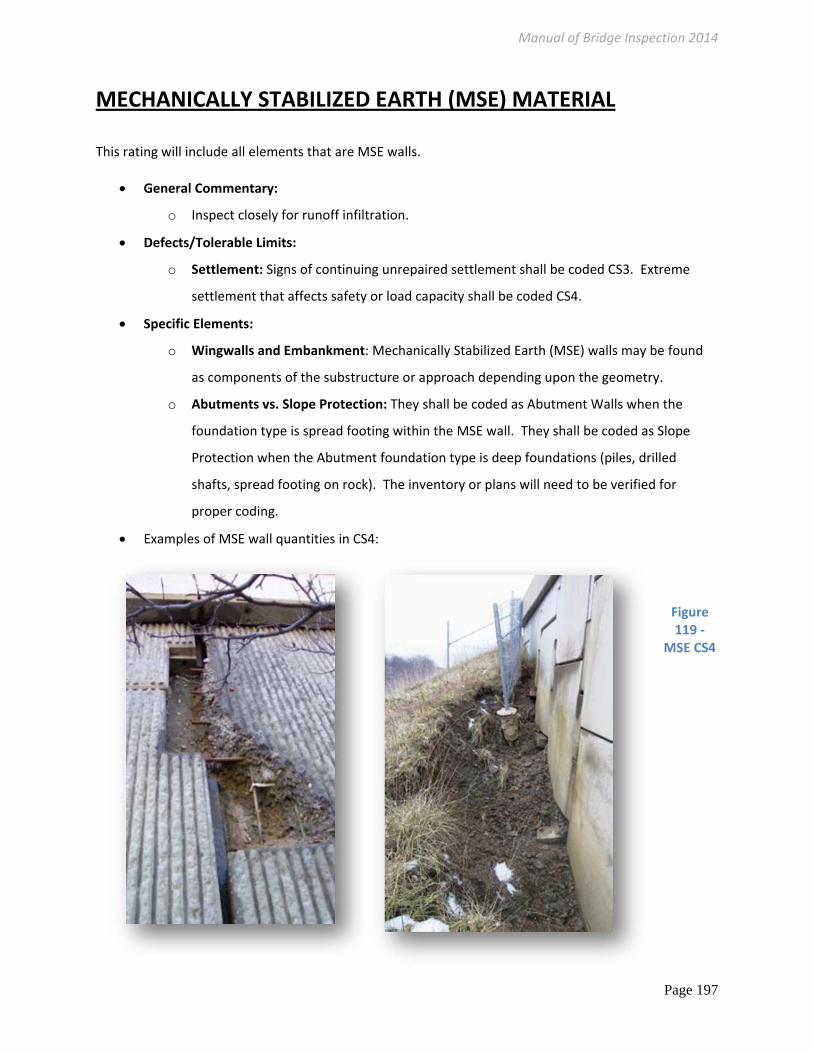
MECHANICALLY STABILIZED EARTH (MSE) MATERIAL
This rating will include all elements that are MSE walls.
General Commentary:
o Inspect closely for runoff infiltration.
Defects/Tolerable Limits:
o Settlement: Signs of continuing unrepaired settlement shall be coded CS3. Extreme
settlement that affects safety or load capacity shall be coded CS4.
Specific Elements:
o Wingwalls and Embankment: Mechanically Stabilized Earth (MSE) walls may be found
as components of the substructure or approach depending upon the geometry.
o Abutments vs. Slope Protection: They shall be coded as Abutment Walls when the
foundation type is spread footing within the MSE wall. They shall be coded as Slope
Protection when the Abutment foundation type is deep foundations (piles, drilled
shafts, spread footing on rock). The inventory or plans will need to be verified for
proper coding.
Examples of MSE wall quantities in CS4:
Figure 119 ‐
MSE CS4
Manual of Bridge Inspection 2014
Page 198
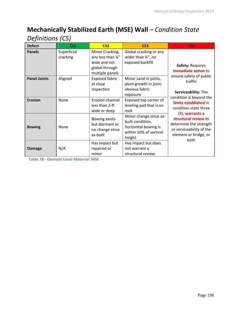
Mechanically Stabilized Earth (MSE) Wall – Condition StateDefinitions (CS) Defect CS1 CS2 CS3 CS4
Panels Superficial cracking
Minor Cracking, any less than ¼” wide and not global through multiple panels
Global cracking or any wider than ¼”, no exposed backfill
Safety: Requires immediate action to ensure safety of public
traffic
Serviceability: The condition is beyond the limits established in condition state three
(3), warrants a structural review to
determine the strength or serviceability of the element or bridge, or
both
Panel Joints Aligned Exposed fabric at close inspection
Minor sand in joints, plant growth in joint, obvious fabric exposure
Erosion None Erosion channel less than 2‐ft wide or deep
Exposed top corner of leveling pad that is on rock
Bowing None
Bowing exists but dormant or no change since as‐built
Minor change since as‐built condition, horizontal bowing is within 10% of vertical height
Damage N/A Has impact but repaired or minor
Has impact but does not warrant a structural review.
Table 78 ‐ Element Level Material: MSE

Manual of Bridge Inspection 2014
Page 199
Element Level Condition State Items with Dedicated Guidance
Approach Embankment – “ded” ELEMENT LEVEL
Item ‐ 4. Embankment
CS1 CS2 CS3 CS4
Moderate rutting from drainage. Minor bare soil exposed.
Erosion caused by drainage or channel; Erosion to embankment impacting guardrail performance or encroaching on shoulder. Evidence of minor or stable foundation settlement.
Major erosion caused by drainage or channel; Erosion to embankment impacting guardrail (up to 6” of guardrail post exposed) performance or encroaching on shoulder. Evidence of foundation settlement.
Tension cracks in asphalt due to embankment movement. Vertical face of guardrail is behind the vertical plane of the edge of pavement. Significant movement or tilt of the wingwall or headwall has occurred, the stability of the slope is compromised
Table 79 –Element Level Approach Embankment
Deck Drainage – “ded” ELEMENT LEVEL
Item ‐ 12. Drainage
Defect CS1 CS2 CS3 CS4
Grating Intact and functioning properly
Intact and functioning, minor problems
Broken or missing grating or
assembly but does NOT pose a
hazard to vehicular or
pedestrian traffic
Broken or missing grating or
assembly may pose a hazard to vehicular or
pedestrian traffic
Scuppers, Downspouts
Open, no ponding
Partially Clogged but no signs of ponding on deck or Downspout is inadequately terminated
Clogged, there are signs of ponding on deck but it does not extend into the striped or normal traffic lane
Clogged, there are signs of ponding in the striped or normal traffic lane.
Table 80 – Element Level Deck Drainage
o Drainage problems are most easily identified during or immediately after a rain event. Unless repaired, deficiencies discovered during a rain events should remain coded.

Manual of Bridge Inspection 2014
Page 200
Table 81 – Element Level Deck Expansion Joint
Deck Expansion Joint – “ded” ELEMENT LEVEL
Item 13‐ Expansion Joint
Defect CS 1 ‐ CS 2 CS 3 CS 4
Leakage None. Minimal. Minor dripping through the joint.
Moderate. More than a drip and less than free flow of water.
Free flow of water through the joint.
Seal Adhesion Fully Adhered. Adhered for more than 50% of the joint height.
Adhered 50% or less of joint height but still some adhesion.
Complete loss of adhesion.
Seal Cracking None. Surface crack. Crack that partially penetrates the seal.
Crack that fully penetrates the seal.
Seal Damage None. Seal abrasion without punctures.
Punctured or ripped or partially pulled out.
Punctured completely through, pulled out, or missing.
Debris Impaction No debris to a shallow cover of loose debris may be evident but does not affect the performance of the joint.
Partially filled with hard‐packed material, but still allowing free movement.
Completely filled and impacts joint movement.
Completely filled and prevents joint movement.
Adjacent Deck or Header
Sound. No spall, delamination or unsound patch.
Edge delamination or spall 1 in. or less deep or 6 in. or less in diameter. No exposed rebar. Patched Area that is sound.
Spall greater than 1 in. deep or greater than 6 in. diameter. Exposed rebar. Delamination or unsound patched Area that makes the joint loose.
Spall, delamination, unsound patched Area or loose joint anchor that prevents the joint from functioning as intended.
Metal Deterioration or Damage
None. Freckled rust, metal has no cracks, or impact damage. Connection may be loose but functioning as intended.
Section loss, missing or broken fasteners, cracking of the metal or impact damage but joint still functioning.
Metal cracking, section loss, damage or connection failure that prevents the joint from functioning as intended.
Damage Not applicable. The element has impact damage not impeding traffic
The element has impact damage. Subtle clanking under traffic
The element has impact damage, LOUD clanking under traffic

Manual of Bridge Inspection 2014
Page 201
Superstructure Truss Gusset Plates – “ded” ELEMENT LEVEL
Item ‐ 23. Truss Gusset Plates
Type ‐ Steel
Defect CS1 CS2 CS3 CS4
Corrosion, Section loss
None
Freckled rust, Minor, surface pitting, loss up to 10% depth
Large areas of corrosion, Between 10‐25% loss of depth
Safety Deficiency: Requires immediate action to ensure safety of public traffic (ex. Buckling, tearing, crack in tension zone, long crack in
compression zone)
Serviceability Deficiency: The condition is beyond the limits established in condition state three (3), warrants a structural
review to determine the strength or serviceability of
the element or bridge, or both (ex. Free edge bowing behind a compression member, Any
worsening of free edge bowing, plastic deformation)
Bowing
None Minor misalignment due to pack rust or inadequate fill plates up to the thickness of the plate
Misalignment due to pack rust or inadequate fill plates more than the thickness of the plate OR Minor Free edge bowing behind a tension member up to the thickness of the plate
Table 82 ‐ Superstructure Gusset Plates Element Level
Special attention shall be placed on gusset plates with corrosion holes or widespread loss of section 1/3 the plate thickness in the primary load path.
Special attention shall be placed on gusset plates with bowing at the free edge.
Special attention shall be placed on gusset plates with loose, cracked or missing connections.
The procedures for measuring bowing in gusset plates shall be clearly documented and quantitatively repeatable at future inspections by different inspectors in order to monitor bowing change within a tolerance of 1/16”.

Manual of Bridge Inspection 2014
Page 202
Table 83 – Element Level Superstructure Bearing Devices
Bearings ‐ “ded” ELEMENT LEVEL Condition State Definitions
Defect CS 1 CS 2 CS 3 CS 4
Corrosion
None. Freckled Rust. Corrosion of the steel has initiated.
Section loss is evident or pack rust is present but does not warrant structural review.
The condition warrants a structural review to determine the effect on strength or serviceability of the element or bridge; OR a structural review has been completed and the defects impact strength or serviceability of the element or bridge.
Connection
Connection is in place and functioning as intended.
Loose fasteners or pack rust without distortion is present but the connection is in place and functioning as intended.
Missing bolts, rivets, broken welds, fasteners or pack rust with distortion but does not warrant a structural review.
Movement
Free to move. Minor restriction. Restricted but not warranting structural review.
Alignment
Lateral and vertical alignment is as expected for the temperature conditions.
Tolerable lateral or vertical alignment that is inconsistent with the temperature conditions.
Approaching the limits of lateral or vertical alignment for the bearing but does not warrant a structural review.
Bulging, Splitting or Tearing
None. Bulging less than 15% of the thickness.
Bulging 15% or more of the thickness. Splitting or tearing. Bearing's surfaces are not parallel. Does not warrant structural review.
Loss of Bearing Area None. Less than 10%. 10% or more but does not warrant structural review.
Damage
Not applicable. The element has minor impact damage.
The element has impact damage but does not warrant a structural review
The element has severe impact damage.

Manual of Bridge Inspection 2014
Page 203
Superstructure Protective Coating System –“ded” ELEMENT LEVEL
Item ‐ 30. Protective Coating System (PCS)
Type – All
Defect CS1 CS2 CS3 CS4
Chalking None Surface dulling Loss of pigment
Peeling/ Curling
None
Initiated, cracking Top coat peeling
Exposure of bare metal
Weathering Steel
Light brown
Yellow orange, localized flaking
Dark brown coloring. Or flaking less than ¼” pieces
Black or flaking more than ¼” pieces
Corrosion None
Light and initiated, freckled rust
Light, large areas of corrosion Heavy, laminating
Effectiveness Fully Substantially Limited Failed, no protection of metal
Comments shall include the existence of obvious workmanship Issues
Table 84 – Element Level Superstructure Protective Coating System

Manual of Bridge Inspection 2014
Page 204
Table 85 – Element Level Superstructure Pins/Hangers/Hinges
Pins/Hangers/Hinges ‐ “ded” ELEMENT LEVEL ‐ Condition State Definitions Item ‐ 31. Pins/Hangers/Hinges
Defect CS 1 CS 2 CS 3 CS 4
Corrosion
None. Freckled Rust. Corrosion of the steel has initiated.
Section loss is evident or pack rust is present but does not warrant structural review.
The condition warrants a structural review to determine the effect on strength or serviceability of the element or bridge; OR a structural review has been completed and the defects impact strength or serviceability of the element or bridge.
Connection
Connection is in place and functioning as intended.
Loose fasteners or pack rust without distortion is present but the connection is in place and functioning as intended.
Missing bolts, rivets, fasteners or pack rust with distortion but does not warrant a structural review.
Movement
Free to move. Minor restriction. Restricted but not warranting structural review.
Alignment
Lateral and vertical alignment is as expected for the temperature conditions.
Tolerable lateral or vertical alignment that is inconsistent with the temperature conditions.
Approaching the limits of lateral or vertical alignment for the bearing but does not warrant a structural review.
Bulging, Splitting or Tearing
None. Bulging less than 15% of the thickness.
Bulging 15% or more of the thickness. Splitting or tearing. Bearing's surfaces are not parallel. Does not warrant structural review.
Loss of Bearing Area None. Less than 10%. 10% or more but does not warrant structural review.
Damage
Not applicable. The element has minor impact damage.
The element has impact damage but does not warrant a structural review
The element has severe impact damage.

Manual of Bridge Inspection 2014
Page 205
Superstructure Fatigue ‐ “ded” ELEMENT LEVEL Condition State Definitions Item ‐ 32. Fatigue
Defect CS1 CS2 CS3 CS4
Fatigue Crack
None Insignificant but should monitor, Repaired or arrested fatigue cracks
Any Initiated or propagated fatigue crack in the compression zone and the total crack length is less than 10% of member depth
Serviceability or Immediate Safety Deficiency: The condition is beyond the limits established in condition state three (3), warrants a structural review to determine the strength or serviceability of the element or bridge, or both. (ex. Any initiated or propagated fatigue crack in tension zone)
o Cracks should be carefully measured and their location and length documented. o Typically the first time a fatigue crack is identified it is CS 3 in the Compression zone and CS4 in the Tension
zone. Table 86 – Element Level Superstructure Fatigue

Manual of Bridge Inspection 2014
Page 206
Substructure Scour– “ded” ELEMENT LEVEL
Item ‐ 42. Scour
Defect CS1 CS2 CS3 CS4
Exposed Deep Foundation (Piling, Drilled Shaft or Spread footing on rock)
None No piles exposed
Piling or drilled shaft exposed less than 10% of the piling or shaft height (use 1.5’ when no plans exist)
Serviceability or Immediate Safety
Deficiency: The condition is beyond the limits
established in condition state three (3), warrants a
structural review to determine the strength or
serviceability of the element or bridge, or both.
Exposed Spread Footing (or Unknown foundations)
None Less than 12" high More than 12" high, no undermining
Undermining None None or arrested by countermeasures
Minor for deep foundations
Table 87 – Element Level Substructure Scour
Substructure Slope Protection – “ded” ELEMENT LEVEL
Item ‐ 43. Slope Protection (use material guidance when applicable)
CS1 CS2 CS3 CS4
Moderate rutting from drainage. Minor bare soil exposed.
Minor Erosion caused by drainage or channel Evidence of minor or stable foundation settlement.
Major erosion caused by drainage or channel; Evidence of foundation settlement.
Severe Erosion caused by drainage or channel Substructure is threatened
Table 88 – Element Level Substructure Slope Protection
Manual of Bridge Inspection 2014
Page 207
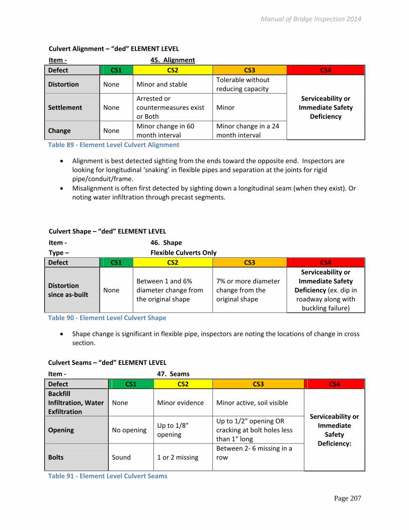
Culvert Alignment – “ded” ELEMENT LEVEL
Item ‐ 45. Alignment
Defect CS1 CS2 CS3 CS4
Distortion None Minor and stable Tolerable without reducing capacity
Serviceability or Immediate Safety
Deficiency Settlement None
Arrested or countermeasures exist or Both
Minor
Change None Minor change in 60 month interval
Minor change in a 24 month interval
Table 89 ‐ Element Level Culvert Alignment
Alignment is best detected sighting from the ends toward the opposite end. Inspectors are looking for longitudinal ‘snaking’ in flexible pipes and separation at the joints for rigid pipe/conduit/frame.
Misalignment is often first detected by sighting down a longitudinal seam (when they exist). Or noting water infiltration through precast segments.
Culvert Shape – “ded” ELEMENT LEVEL
Item ‐ 46. Shape
Type – Flexible Culverts Only
Defect CS1 CS2 CS3 CS4
Distortion since as‐built
None Between 1 and 6% diameter change from the original shape
7% or more diameter change from the original shape
Serviceability or Immediate Safety
Deficiency (ex. dip in roadway along with buckling failure)
Table 90 ‐ Element Level Culvert Shape
Shape change is significant in flexible pipe, inspectors are noting the locations of change in cross section.
Culvert Seams – “ded” ELEMENT LEVEL
Item ‐ 47. Seams
Defect CS1 CS2 CS3 CS4
Backfill Infiltration, Water Exfiltration
None Minor evidence Minor active, soil visible
Serviceability or Immediate Safety
Deficiency:
Opening No opening Up to 1/8" opening
Up to 1/2" opening OR cracking at bolt holes less than 1" long
Bolts Sound 1 or 2 missing Between 2‐ 6 missing in a row
Table 91 ‐ Element Level Culvert Seams

Manual of Bridge Inspection 2014
Page 208
Culvert Scour– “ded” ELEMENT LEVEL
Item ‐ 49. Scour
Defect CS1 CS2 CS3 CS4
Scour None
Exists within tolerable limits or has been arrested with effective countermeasures
Exceeds tolerable limits but is less than the critical limits determined by scour evaluation and does not warrant a structural review. Serviceability or
Immediate Safety Deficiency:.
Exposed Spread Footing (or Unknown foundations)
None Less than 12" high More than 12" high, no undermining
Undermining/ Piping
None None or arrested by countermeasures
Minor but stable
Table 92 ‐ Element Level Culvert Scour

Manual of Bridge Inspection 2014
Page 209
Channel Alignment – “ded” ELEMENT LEVEL
Item ‐ 51. Alignment
Type – All
Defect CS1 CS2 CS3 CS4
Direction As constructed
Minor problems, Misalignment, Angle has changed to now flow against substructure unit
Misaligned , Flow Along wall to expose footing or behind wingwall but structure is still stable
Serviceability or Immediate Safety Deficiency: The condition is beyond the limits established in condition state three (3), warrants a structural review to determine the strength or serviceability of the element or bridge, or both.
Table 93 ‐ Element Level Channel Alignment
Channel Protection – “ded” ELEMENT LEVEL
Item ‐ 52. Protection
Defect CS1 CS2 CS3 CS4
Erosion None Minor Advanced Serviceability or Immediate Safety Deficiency: The
condition is beyond the limits established in condition state three
(3), warrants a structural review to
determine the strength or serviceability of the element or bridge, or
both.
Counter measures
Present Minor damage Undermined, rip rap washed away, structure is still stable
Banks Stable Minor slumping Slumping
Table 94 ‐ Element Level Channel Protection
Materials CS charts may be utilized for further guidance when material deficiencies exist

Manual of Bridge Inspection 2014
Page 210
Channel Hydraulic Opening – “ded” ELEMENT LEVEL
Item ‐ 53. Hydraulic Opening
Type – All
Defect CS1 CS2 CS3 CS4
% of Debris Buildup Below the ordinary high water elevation
at each substructure unit OR
of the span length blocked by each substructure unit
None Minor debris, or Debris exists but it is not detrimental to substructure unit or channel
Debris is not detrimental to the substructure unit or channel but if left unchecked it may pose a problem before the next scheduled inspection. For Non‐Scour Critical Bridges: Any Debris that IS causing scour.
Scour Critical Bridges: Any Debris that MAY cause scour. For Non‐Scour Critical Bridges: Any Debris that IS causing undermining. Excessive, Debris is causing excessive: drag, turbulence near substructure units, flow accelerating existing scour
Table 95‐ Element Level Channel Hydraulic Opening
History of overtopping: Code 100% in CS 4 if there is a history of overtopping within three years. Code 100% in CS 3 if there is a history of overtopping within the past ten years. Code 100% in CS 2 if there is debris in crossframes with no historical overtopping knowledge.
Channel Navigation Lights – “ded” ELEMENT LEVEL
Item ‐ 54. Navigation Lights, 55. Signs, 56. Sign Supports, 57. Utilities
Defect CS1 CS2 CS3 CS4
Light or Sign Functioning Functioning
Functioning, Partially blocked or missing but no exposed wires, problems are not affecting bridge elements or public safety
Obstructed, not visible to intended traffic, missing or broken, exposed wires
Supports Properly anchored and sound
Minor problem, active corrosion, loose joints but no exposed wires or leaks
Loose or missing support element but the utility is adequately supported, problems are not affecting bridge elements or public safety
Broken or missing supports, affecting bridge element of public safety
Encasement Sound Sound with minor problem
Seal broken, cracked, problems are not affecting bridge elements or public safety
Collecting moisture, broken and leaking onto roadway, trail or bridge elements
Fatigue No indications
No indications
There may be some indications of fatigue
Fatigue cracks
Table 96‐ Element Level Navigation Lights, Signs, Sign Supports, Utilities