chapter 9 actuators - pbworks
TRANSCRIPT
1
Chapter 9Chapter 9
ActuatorsActuators
Workhorses of the SystemWorkhorses of the Systemf yf y
2
ObjectivesObjectives
Describe the construction and operation of basic hydraulic cylinders limited-rotationbasic hydraulic cylinders, limited rotation actuators, and motors. Compare the design and operation of various
types of hydraulic cylinders. Select appropriate cylinder design options
available for mounting hydraulic cylinders and
© Goodheart-Willcox Co., Inc. Permission granted to reproduce for educational use only.3
reducing hydraulic shock. Compare the design and operation of various
types of hydraulic motors.
ObjectivesObjectives
Contrast the operation of fixed- and variable-speed hydraulic motorsspeed hydraulic motors. Describe the construction and operation of a
basic hydrostatic transmission. Size hydraulic cylinders and motors to correctly
meet system force and speed requirements. Interpret manufacturer specifications for
© Goodheart-Willcox Co., Inc. Permission granted to reproduce for educational use only.4
Interpret manufacturer specifications for hydraulic cylinders.
3
Hydraulic CylindersHydraulic Cylinders
Actuators are the components used in a h d li t t id t i dhydraulic system to provide power to a required work location
Cylinders are the hydraulic system components that convert fluid pressure and flow into linear mechanical force and movement
© Goodheart-Willcox Co., Inc. Permission granted to reproduce for educational use only.5
mechanical force and movement
Hydraulic CylindersHydraulic Cylinders
A basic cylinder consists of:– Piston
– Piston rod
– Barrel
© Goodheart-Willcox Co., Inc. Permission granted to reproduce for educational use only.6
4
Hydraulic CylindersHydraulic Cylinders
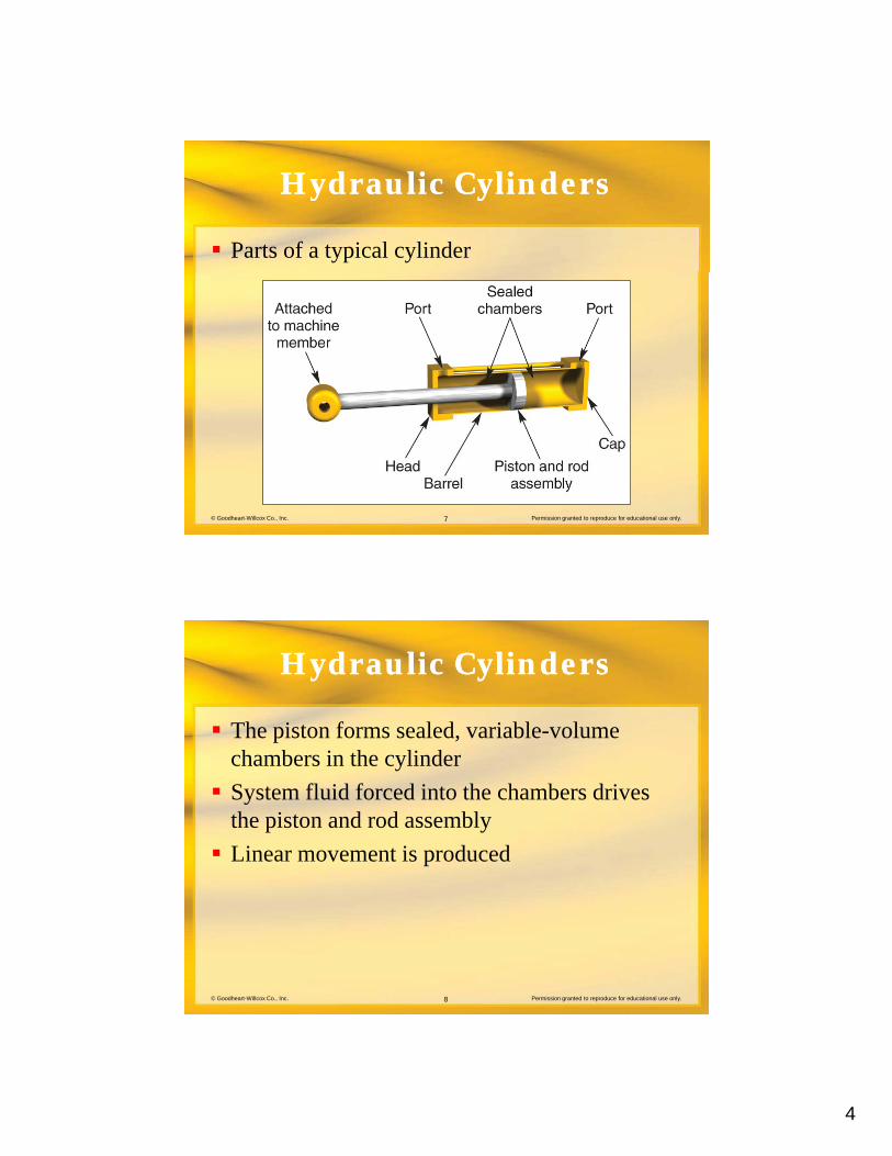
Parts of a typical cylinder
© Goodheart-Willcox Co., Inc. Permission granted to reproduce for educational use only.7
Hydraulic CylindersHydraulic Cylinders
The piston forms sealed, variable-volume h b i th li dchambers in the cylinder
System fluid forced into the chambers drives the piston and rod assembly
Linear movement is produced
© Goodheart-Willcox Co., Inc. Permission granted to reproduce for educational use only.8
5
Hydraulic CylindersHydraulic Cylinders
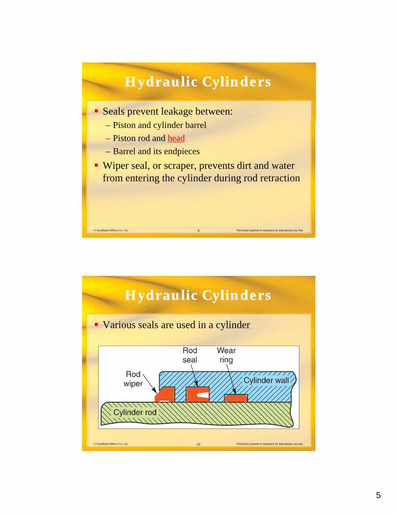
Seals prevent leakage between:– Piston and cylinder barrel
– Piston rod and head
– Barrel and its endpieces
Wiper seal, or scraper, prevents dirt and water from entering the cylinder during rod retraction
© Goodheart-Willcox Co., Inc. Permission granted to reproduce for educational use only.9
from entering the cylinder during rod retraction
Hydraulic CylindersHydraulic Cylinders
Various seals are used in a cylinder
© Goodheart-Willcox Co., Inc. Permission granted to reproduce for educational use only.10
6
Hydraulic CylindersHydraulic Cylinders
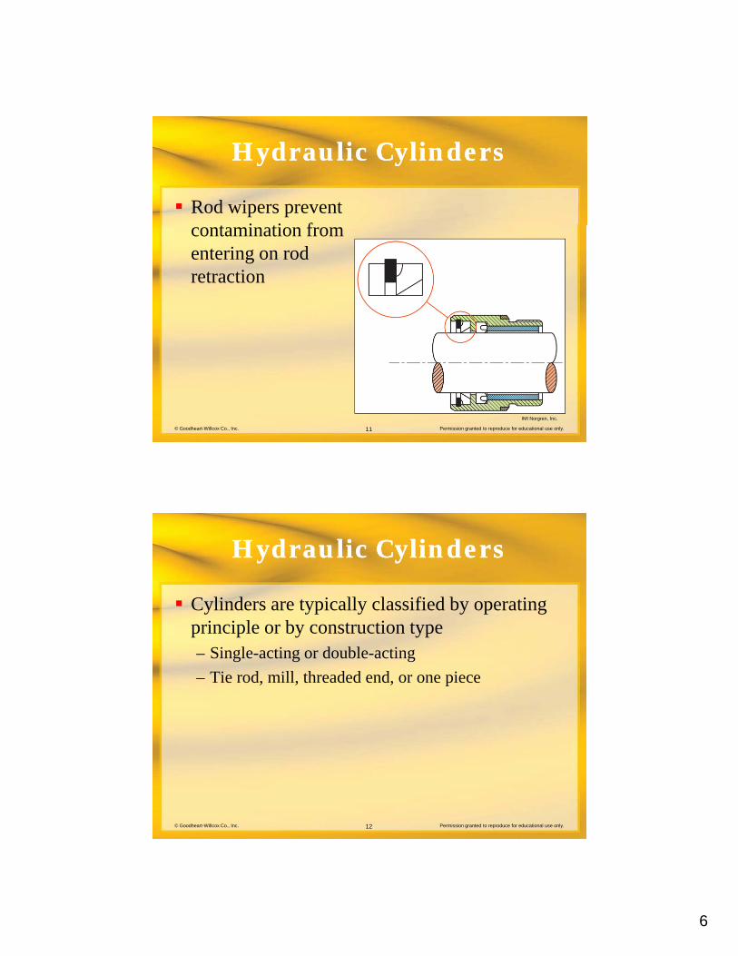
Rod wipers prevent t i ti fcontamination from
entering on rod retraction
© Goodheart-Willcox Co., Inc. Permission granted to reproduce for educational use only.11
IMI Norgren, Inc.
Hydraulic CylindersHydraulic Cylinders
Cylinders are typically classified by operating i i l b t ti tprinciple or by construction type
– Single-acting or double-acting
– Tie rod, mill, threaded end, or one piece
© Goodheart-Willcox Co., Inc. Permission granted to reproduce for educational use only.12
7
Hydraulic CylindersHydraulic Cylinders
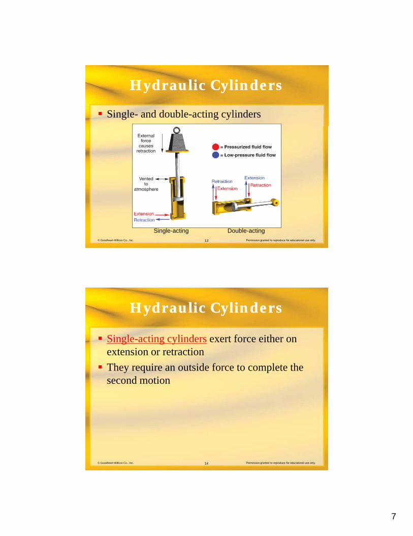
Single- and double-acting cylinders
© Goodheart-Willcox Co., Inc. Permission granted to reproduce for educational use only.13
Single-acting Double-acting
Hydraulic CylindersHydraulic Cylinders
Single-acting cylinders exert force either on t i t tiextension or retraction
They require an outside force to complete the second motion
© Goodheart-Willcox Co., Inc. Permission granted to reproduce for educational use only.14
8
Hydraulic CylindersHydraulic Cylinders
Double-acting cylinders generate force during b th t i d t tiboth extension and retraction– Directional control valve alternately directs fluid to
opposite sides of the piston
– Force output varies between extension and retraction
© Goodheart-Willcox Co., Inc. Permission granted to reproduce for educational use only.15
Hydraulic CylindersHydraulic Cylinders
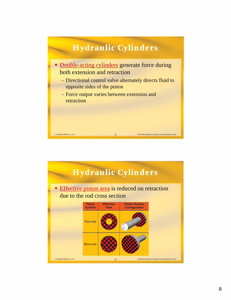
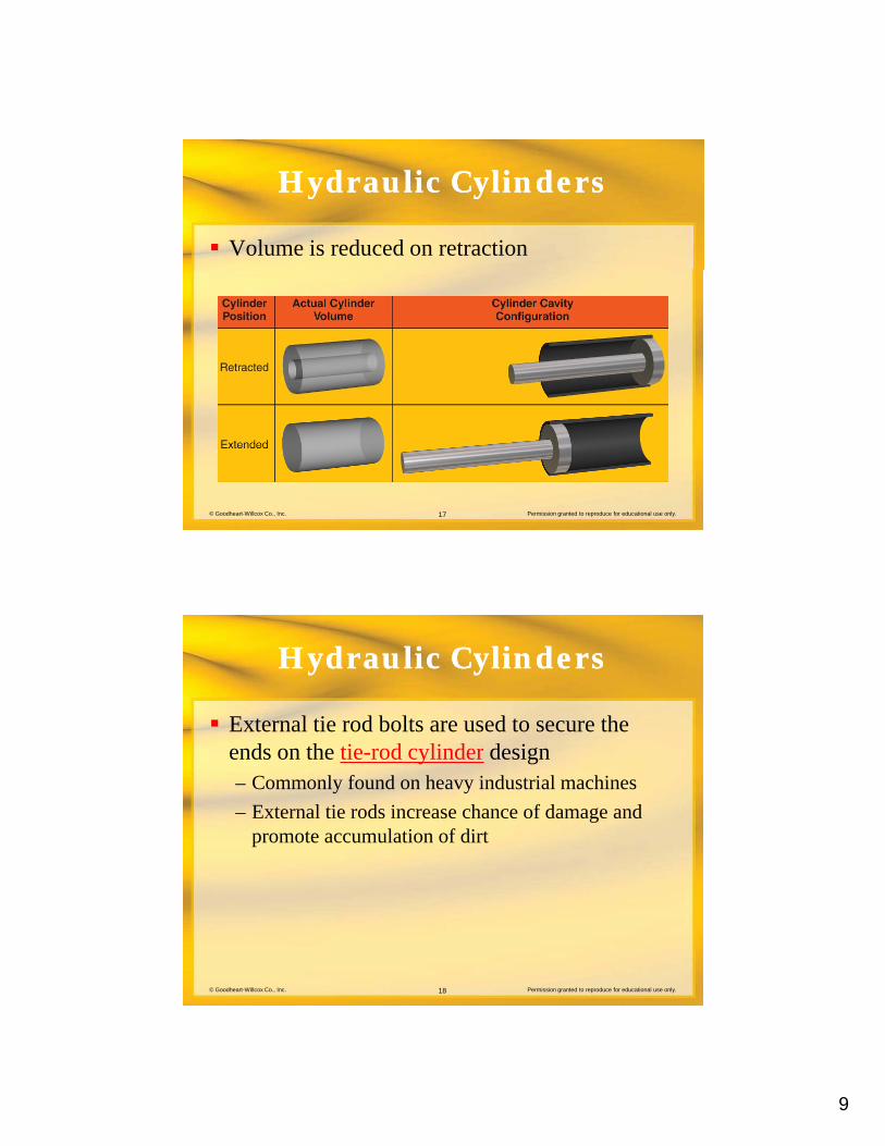
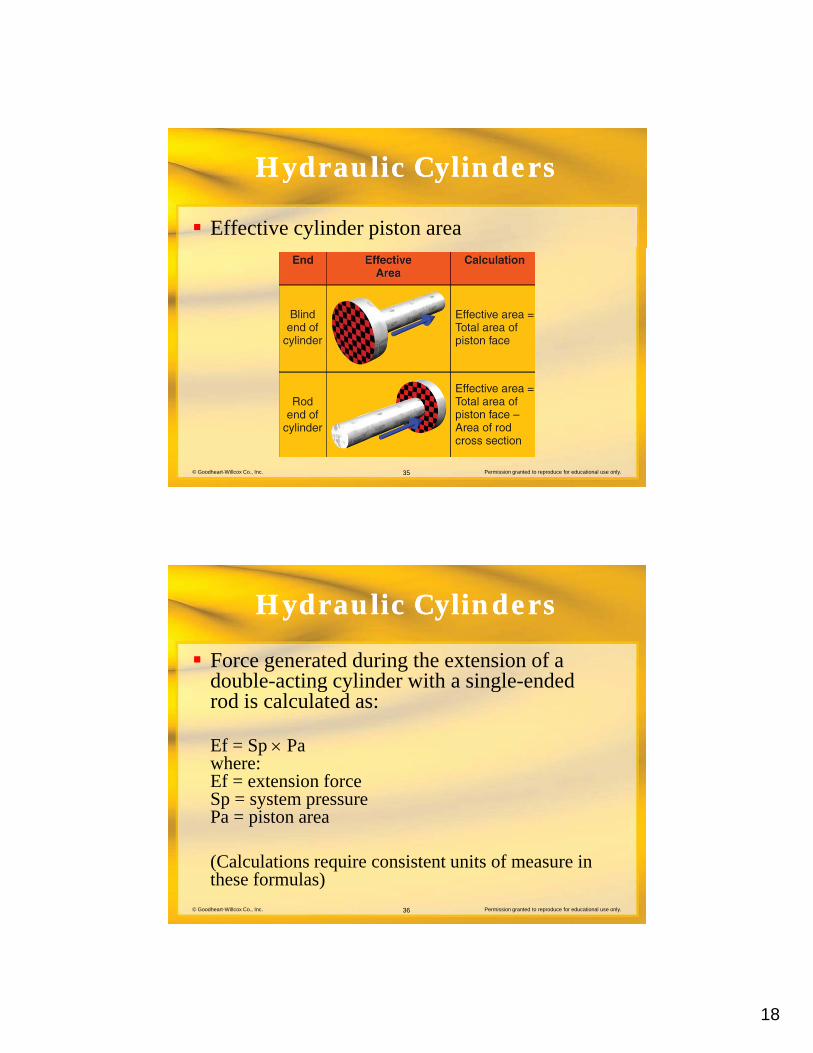
Effective piston area is reduced on retraction due to the rod cross sectiondue to the rod cross section
© Goodheart-Willcox Co., Inc. Permission granted to reproduce for educational use only.16
9
Hydraulic CylindersHydraulic Cylinders
Volume is reduced on retraction
© Goodheart-Willcox Co., Inc. Permission granted to reproduce for educational use only.17
Hydraulic CylindersHydraulic Cylinders
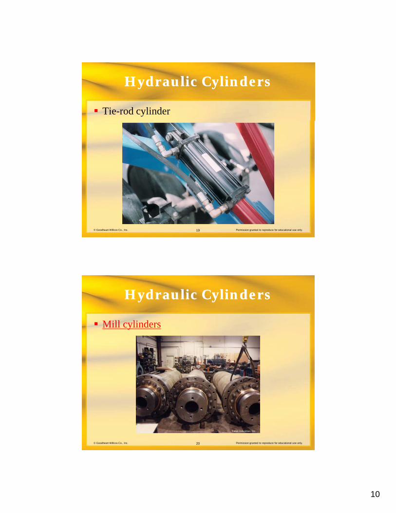
External tie rod bolts are used to secure the d th ti d li d d iends on the tie-rod cylinder design
– Commonly found on heavy industrial machines
– External tie rods increase chance of damage and promote accumulation of dirt
© Goodheart-Willcox Co., Inc. Permission granted to reproduce for educational use only.18
10
Hydraulic CylindersHydraulic Cylinders
Tie-rod cylinder
© Goodheart-Willcox Co., Inc. Permission granted to reproduce for educational use only.19
Hydraulic CylindersHydraulic Cylinders
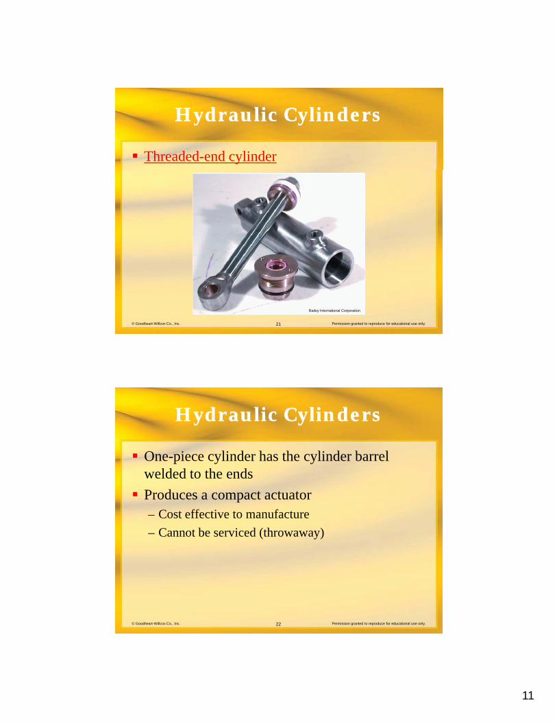
Mill cylinders
© Goodheart-Willcox Co., Inc. Permission granted to reproduce for educational use only.20
Yates Industries, Inc.
11
Hydraulic CylindersHydraulic Cylinders
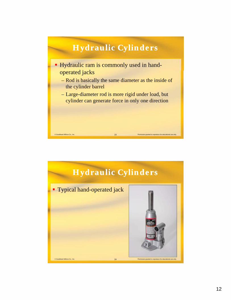
Threaded-end cylinder
© Goodheart-Willcox Co., Inc. Permission granted to reproduce for educational use only.21
Bailey International Corporation
Hydraulic CylindersHydraulic Cylinders
One-piece cylinder has the cylinder barrel ld d t th dwelded to the ends
Produces a compact actuator– Cost effective to manufacture
– Cannot be serviced (throwaway)
© Goodheart-Willcox Co., Inc. Permission granted to reproduce for educational use only.22
12
Hydraulic CylindersHydraulic Cylinders
Hydraulic ram is commonly used in hand-t d j koperated jacks
– Rod is basically the same diameter as the inside of the cylinder barrel
– Large-diameter rod is more rigid under load, but cylinder can generate force in only one direction
© Goodheart-Willcox Co., Inc. Permission granted to reproduce for educational use only.23
Hydraulic CylindersHydraulic Cylinders
Typical hand-operated jack
© Goodheart-Willcox Co., Inc. Permission granted to reproduce for educational use only.24
13
Hydraulic CylindersHydraulic Cylinders
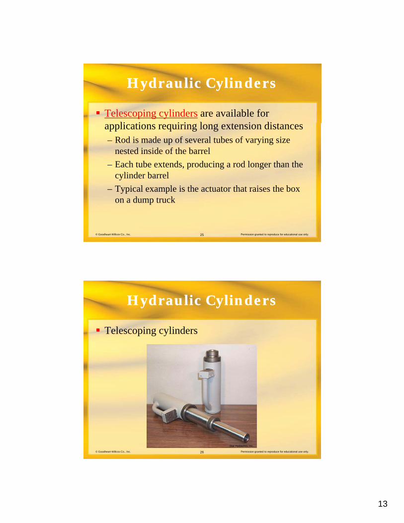
Telescoping cylinders are available for li ti i i l t i di tapplications requiring long extension distances
– Rod is made up of several tubes of varying size nested inside of the barrel
– Each tube extends, producing a rod longer than the cylinder barrel
© Goodheart-Willcox Co., Inc. Permission granted to reproduce for educational use only.25
– Typical example is the actuator that raises the box on a dump truck
Hydraulic CylindersHydraulic Cylinders
Telescoping cylinders
© Goodheart-Willcox Co., Inc. Permission granted to reproduce for educational use only.26
Star Hydraulics, Inc.
14
Hydraulic CylindersHydraulic Cylinders
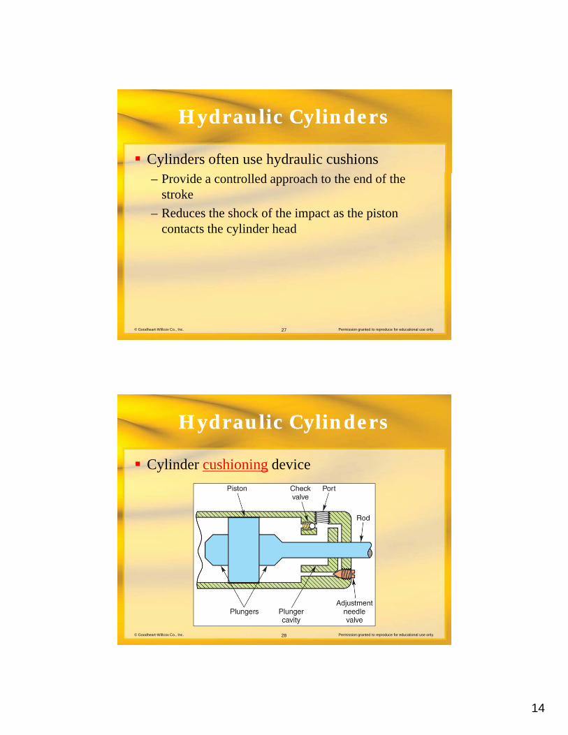
Cylinders often use hydraulic cushions– Provide a controlled approach to the end of the
stroke
– Reduces the shock of the impact as the piston contacts the cylinder head
© Goodheart-Willcox Co., Inc. Permission granted to reproduce for educational use only.27
Hydraulic CylindersHydraulic Cylinders
Cylinder cushioning device
© Goodheart-Willcox Co., Inc. Permission granted to reproduce for educational use only.28
15
Hydraulic CylindersHydraulic Cylinders
A variety of mounting configurations are used t tt h th li d b d d d d tto attach the cylinder body and rod end to machinery– Fixed centerline
– Fixed noncenterline
– Pivoting centerline
© Goodheart-Willcox Co., Inc. Permission granted to reproduce for educational use only.29
g
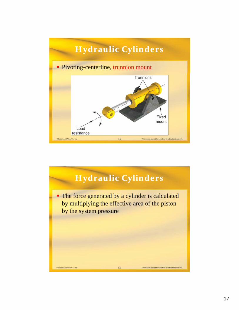
– Expected cylinder loading is the major factor in the selection of the mounting style
Hydraulic CylindersHydraulic Cylinders
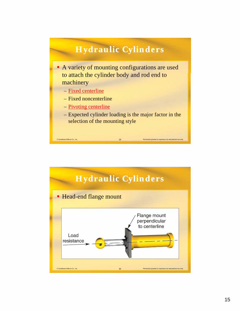
Head-end flange mount
© Goodheart-Willcox Co., Inc. Permission granted to reproduce for educational use only.30
16
Hydraulic CylindersHydraulic Cylinders
Fixed-noncenterline mount
© Goodheart-Willcox Co., Inc. Permission granted to reproduce for educational use only.31
Hydraulic CylindersHydraulic Cylinders
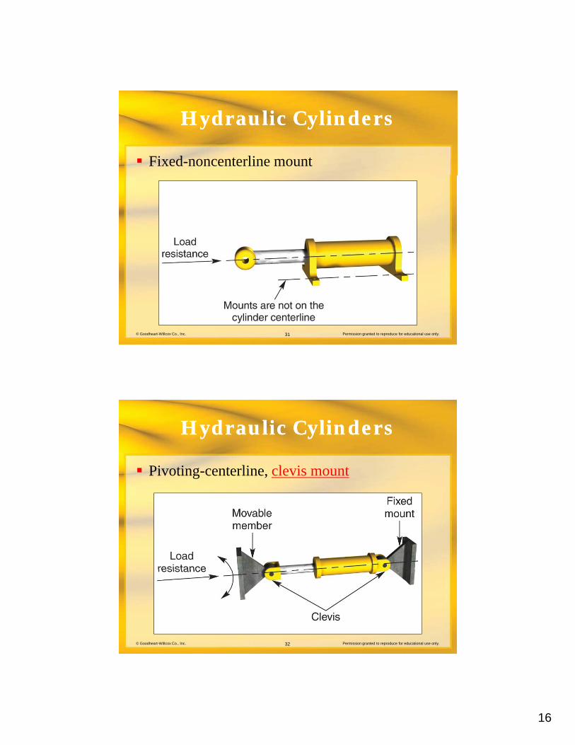
Pivoting-centerline, clevis mount
© Goodheart-Willcox Co., Inc. Permission granted to reproduce for educational use only.32
17
Hydraulic CylindersHydraulic Cylinders
Pivoting-centerline, trunnion mount
© Goodheart-Willcox Co., Inc. Permission granted to reproduce for educational use only.33
Hydraulic CylindersHydraulic Cylinders
The force generated by a cylinder is calculated b lti l i th ff ti f th i tby multiplying the effective area of the piston by the system pressure
© Goodheart-Willcox Co., Inc. Permission granted to reproduce for educational use only.34
18
Hydraulic CylindersHydraulic Cylinders
Effective cylinder piston area
© Goodheart-Willcox Co., Inc. Permission granted to reproduce for educational use only.35
Hydraulic CylindersHydraulic Cylinders
Force generated during the extension of a double-acting cylinder with a single-endeddouble acting cylinder with a single ended rod is calculated as:
Ef = Sp Pawhere:Ef = extension forceSp = system pressure
© Goodheart-Willcox Co., Inc. Permission granted to reproduce for educational use only.36
Sp system pressurePa = piston area
(Calculations require consistent units of measure in these formulas)
19
Hydraulic CylindersHydraulic Cylinders
Force generated during the retraction of a d bl ti li d ith i l d d ddouble-acting cylinder with a single-ended rod is calculated as:Rf = Sp (Pa – Ra)where:Rf = retraction force
© Goodheart-Willcox Co., Inc. Permission granted to reproduce for educational use only.37
Sp = system pressurePa = piston areaRa = rod area
Hydraulic CylindersHydraulic Cylinders
Speed at which the cylinder extends or retracts i d t i d bis determined by:– Physical volume per inch of cylinder piston travel
– Amount of fluid entering the cylinder
Effective area of the piston is used to calculate the volume of the cylinder per inch of piston
© Goodheart-Willcox Co., Inc. Permission granted to reproduce for educational use only.38
the volume of the cylinder per inch of piston travel
20
Hydraulic CylindersHydraulic Cylinders
Extension speed of a double-acting cylinder ith i l d d d i l l t dwith a single-ended rod is calculated as:
Es = Fr (Cg Pa)where:Es = extension speedFr = flow delivery rate
© Goodheart-Willcox Co., Inc. Permission granted to reproduce for educational use only.39
Cg = cubic inches in one gallonPa = piston area
Hydraulic CylindersHydraulic Cylinders
Calculate retraction speed of a double-acting li d ith i l d d dcylinder with single-ended rod as:
Rs = Fr [Cg (Pa – Ra)]where:Rs = retraction speedFr = flow delivery rate
© Goodheart-Willcox Co., Inc. Permission granted to reproduce for educational use only.40
Cg = cubic inches in one gallonPa = piston areaRa = rod area
21
Hydraulic CylindersHydraulic Cylinders
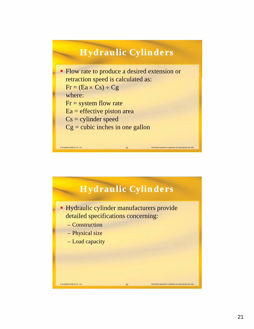
Flow rate to produce a desired extension or t ti d i l l t dretraction speed is calculated as:
Fr = (Ea Cs) Cgwhere:Fr = system flow rateEa = effective piston area
© Goodheart-Willcox Co., Inc. Permission granted to reproduce for educational use only.41
Cs = cylinder speedCg = cubic inches in one gallon
Hydraulic CylindersHydraulic Cylinders
Hydraulic cylinder manufacturers provide d t il d ifi ti idetailed specifications concerning:– Construction
– Physical size
– Load capacity
© Goodheart-Willcox Co., Inc. Permission granted to reproduce for educational use only.42
22
Hydraulic CylindersHydraulic Cylinders
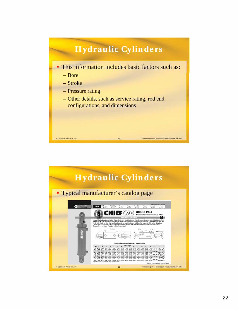
This information includes basic factors such as:– Bore
– Stroke
– Pressure rating
– Other details, such as service rating, rod end configurations, and dimensions
© Goodheart-Willcox Co., Inc. Permission granted to reproduce for educational use only.43
g ,
Hydraulic CylindersHydraulic Cylinders
Typical manufacturer’s catalog page
© Goodheart-Willcox Co., Inc. Permission granted to reproduce for educational use only.44
Bailey International Corporation
23
LimitedLimited--RotationRotationHydraulic ActuatorsHydraulic Actuators
Limited-rotation devices are actuators with an t t h ft th t t i ll li toutput shaft that typically applies torque
through approximately 360° of rotation
Models are available that are limited to less than one revolution, while others may produce several revolutions
© Goodheart-Willcox Co., Inc. Permission granted to reproduce for educational use only.45
several revolutions
LimitedLimited--RotationRotationHydraulic ActuatorsHydraulic Actuators
Most common designs of limited-rotation t tactuators are:
– Rack-and-pinion
– Vane
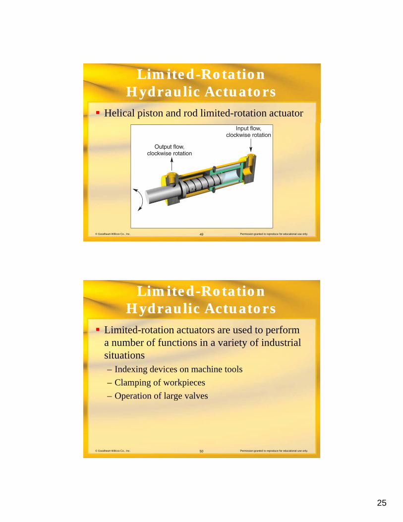
– Helical piston and rod
© Goodheart-Willcox Co., Inc. Permission granted to reproduce for educational use only.46
24
LimitedLimited--RotationRotationHydraulic ActuatorsHydraulic Actuators
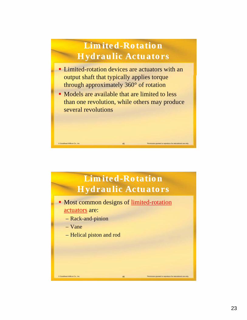
Rack-and-pinion limited rotation actuator
© Goodheart-Willcox Co., Inc. Permission granted to reproduce for educational use only.47
IMI Norgren, Inc.
LimitedLimited--RotationRotationHydraulic ActuatorsHydraulic Actuators
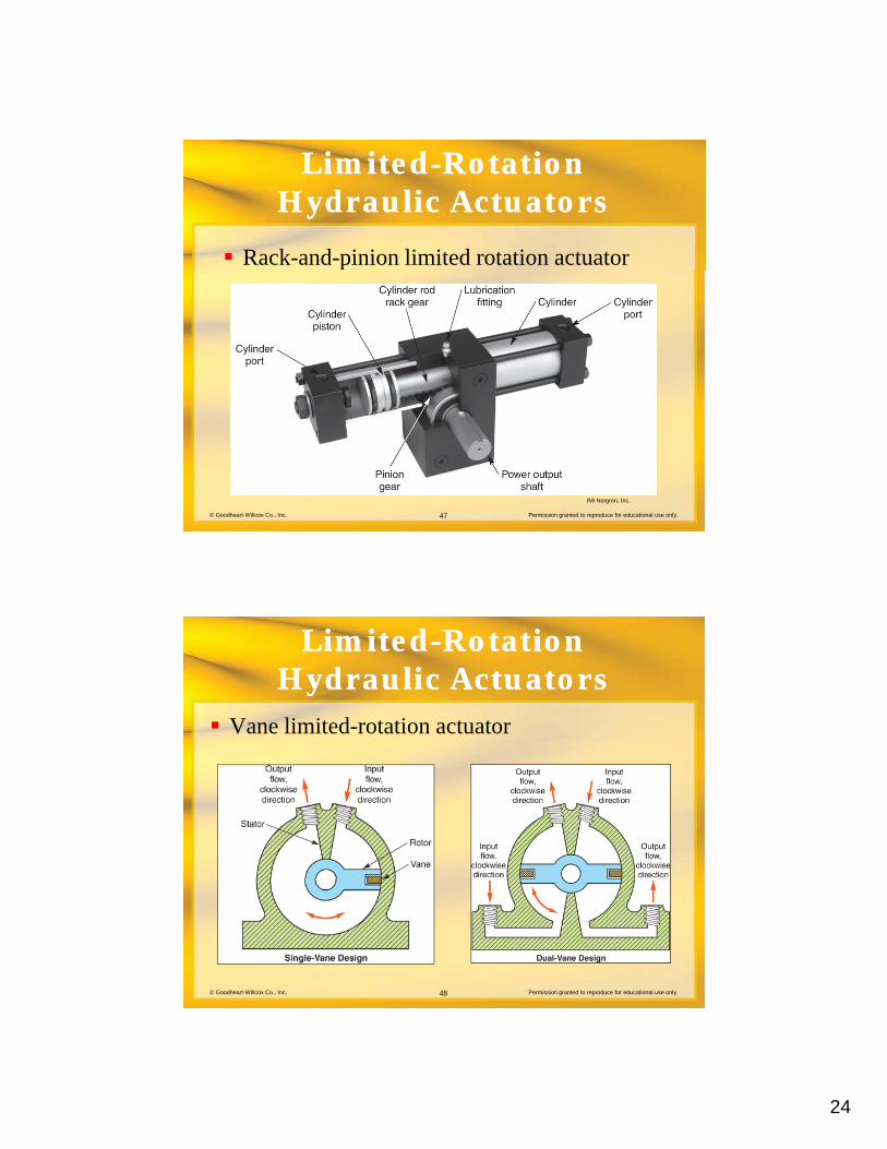
Vane limited-rotation actuator
© Goodheart-Willcox Co., Inc. Permission granted to reproduce for educational use only.48
25
LimitedLimited--RotationRotationHydraulic ActuatorsHydraulic Actuators
Helical piston and rod limited-rotation actuator
© Goodheart-Willcox Co., Inc. Permission granted to reproduce for educational use only.49
LimitedLimited--RotationRotationHydraulic ActuatorsHydraulic Actuators
Limited-rotation actuators are used to perform b f f ti i i t f i d t i la number of functions in a variety of industrial
situations– Indexing devices on machine tools
– Clamping of workpieces
– Operation of large valves
© Goodheart-Willcox Co., Inc. Permission granted to reproduce for educational use only.50
p g
26
LimitedLimited--RotationRotationHydraulic ActuatorsHydraulic Actuators
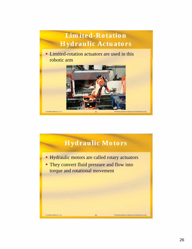
Limited-rotation actuators are used in this b tirobotic arm
© Goodheart-Willcox Co., Inc. Permission granted to reproduce for educational use only.51
IMI Norgren, Inc.
Hydraulic MotorsHydraulic Motors
Hydraulic motors are called rotary actuators
They convert fluid pressure and flow into torque and rotational movement
© Goodheart-Willcox Co., Inc. Permission granted to reproduce for educational use only.52
27
Hydraulic MotorsHydraulic Motors
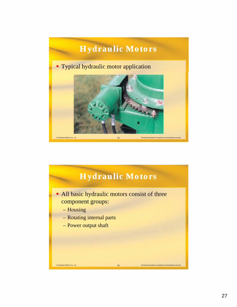
Typical hydraulic motor application
© Goodheart-Willcox Co., Inc. Permission granted to reproduce for educational use only.53
Hydraulic MotorsHydraulic Motors
All basic hydraulic motors consist of three tcomponent groups:
– Housing
– Rotating internal parts
– Power output shaft
© Goodheart-Willcox Co., Inc. Permission granted to reproduce for educational use only.54
28
Hydraulic MotorsHydraulic Motors
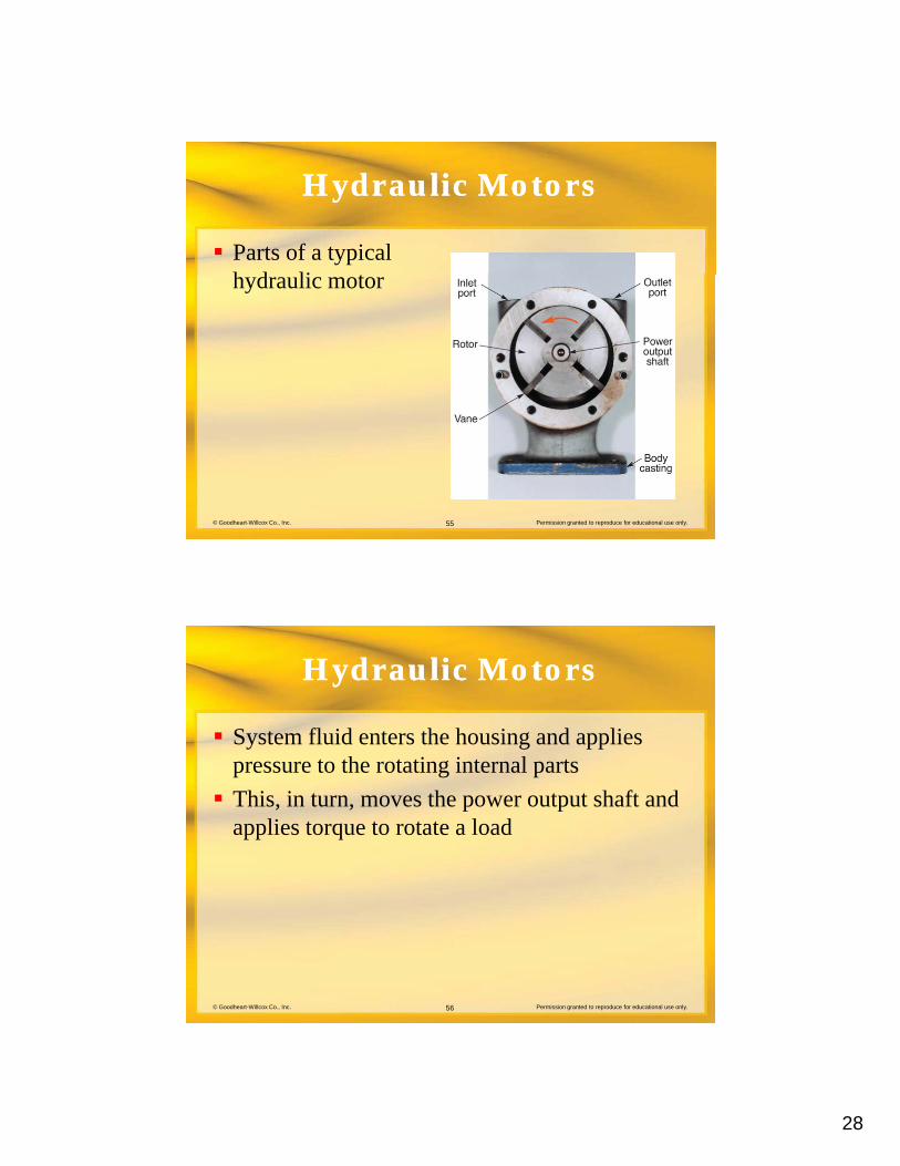
Parts of a typical h d li thydraulic motor
© Goodheart-Willcox Co., Inc. Permission granted to reproduce for educational use only.55
Hydraulic MotorsHydraulic Motors
System fluid enters the housing and applies t th t ti i t l tpressure to the rotating internal parts
This, in turn, moves the power output shaft and applies torque to rotate a load
© Goodheart-Willcox Co., Inc. Permission granted to reproduce for educational use only.56
29
Hydraulic MotorsHydraulic Motors
Primary parts that produce the rotating motion i t h d li t ithin most hydraulic motors are either:– Gears
– Vanes
– Pistons
© Goodheart-Willcox Co., Inc. Permission granted to reproduce for educational use only.57
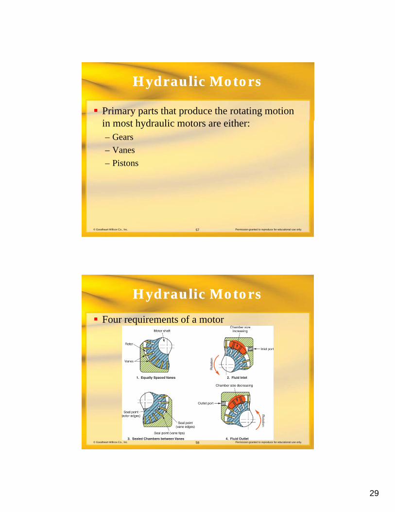
Hydraulic MotorsHydraulic Motors
Four requirements of a motor
© Goodheart-Willcox Co., Inc. Permission granted to reproduce for educational use only.58
30
Hydraulic MotorsHydraulic Motors
Displacement of a hydraulic motor indicates th l f fl id d d t t th t tthe volume of fluid needed to turn the output shaft one revolution– Fixed displacement
– Variable displacement
© Goodheart-Willcox Co., Inc. Permission granted to reproduce for educational use only.59
Hydraulic MotorsHydraulic Motors
In a fixed-displacement motor:– Internal geometry cannot be changed
– Same volume needed per output shaft revolution
© Goodheart-Willcox Co., Inc. Permission granted to reproduce for educational use only.60
31
Hydraulic MotorsHydraulic Motors
In a variable-displacement motor:– Internal geometry can be changed
– Displacement per shaft revolution can be adjusted
– Motor can operate at variable speeds with a constant input flow
© Goodheart-Willcox Co., Inc. Permission granted to reproduce for educational use only.61
Hydraulic MotorsHydraulic Motors
Hydraulic motors may be classified by the type f l d li d t th b i f th t tof load applied to the bearings of the output
shaft– Unbalanced indicates the output shaft is loaded
from one side, side loading the shaft bearings
– Balanced indicates the bearing load is balanced by
© Goodheart-Willcox Co., Inc. Permission granted to reproduce for educational use only.62
use of two inlet ports arranged opposite of each other and two outlet ports similarly arranged
32
Hydraulic MotorsHydraulic Motors
The external gear hydraulic motor is the most d i l t f th b i t tcommon and simplest of the basic motor types
– Fixed displacement
– Unbalanced load on the bearings
© Goodheart-Willcox Co., Inc. Permission granted to reproduce for educational use only.63
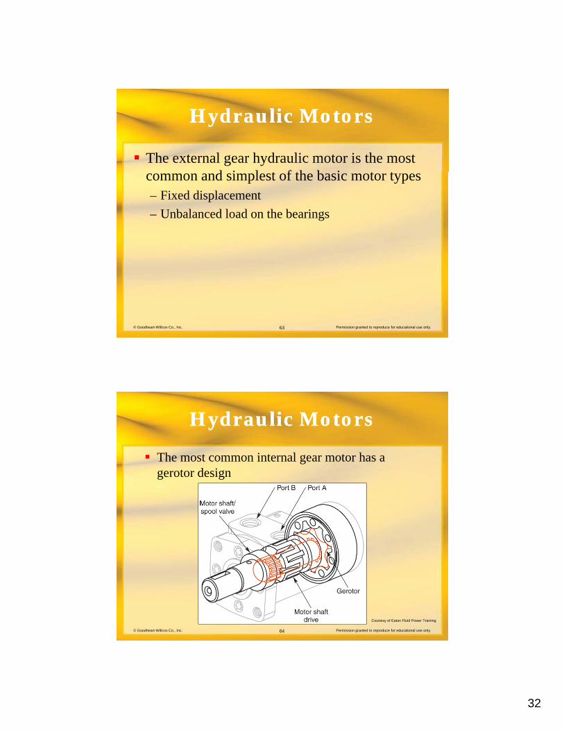
Hydraulic MotorsHydraulic Motors
The most common internal gear motor has a gerotor designgerotor design
© Goodheart-Willcox Co., Inc. Permission granted to reproduce for educational use only.64
Courtesy of Eaton Fluid Power Training
33
Hydraulic MotorsHydraulic Motors
The specially shaped gear teeth of the gerotor f i bl l h b th t llform variable-volume chambers that allow system fluid flow and pressure to turn the motor output shaft
Gerotor motors are fixed-displacement units operating with an unbalanced bearing load
© Goodheart-Willcox Co., Inc. Permission granted to reproduce for educational use only.65
operating with an unbalanced bearing load
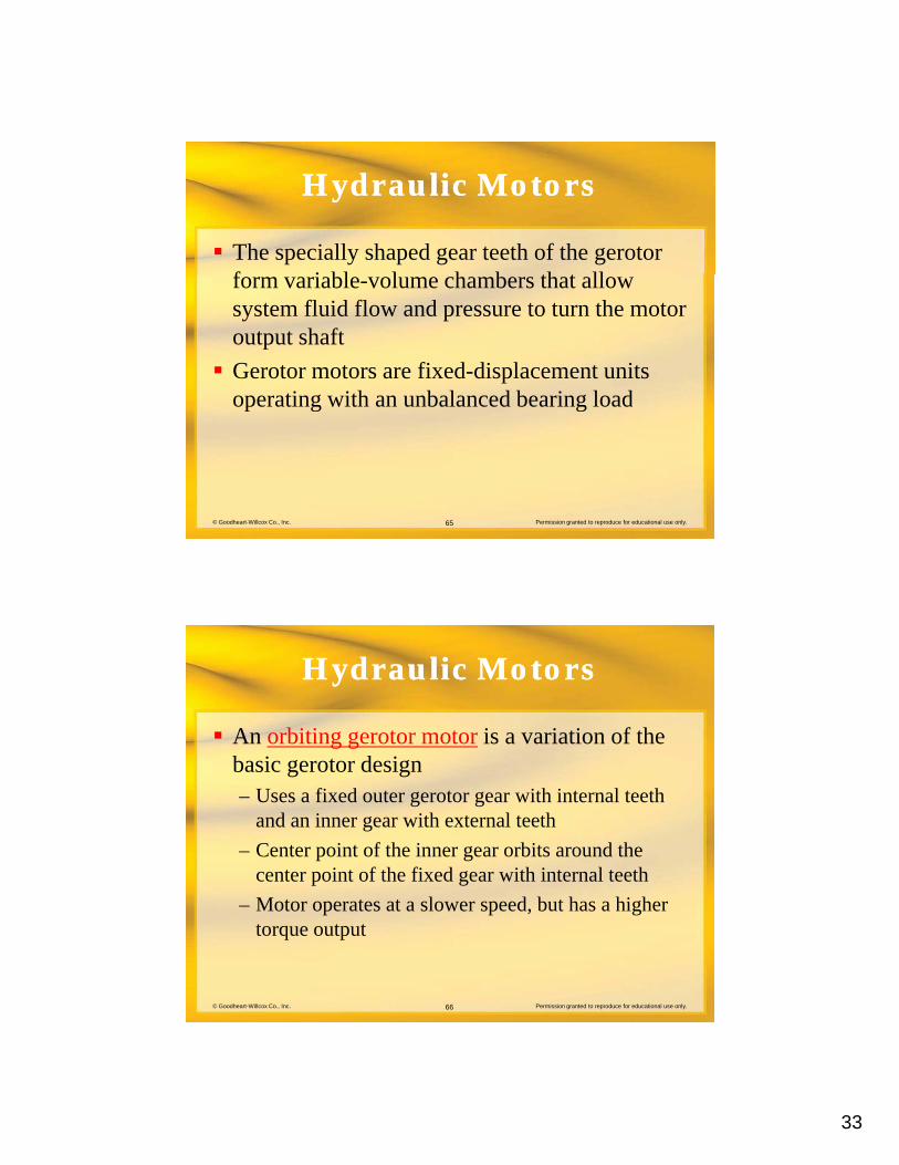
Hydraulic MotorsHydraulic Motors
An orbiting gerotor motor is a variation of the b i t d ibasic gerotor design– Uses a fixed outer gerotor gear with internal teeth
and an inner gear with external teeth
– Center point of the inner gear orbits around the center point of the fixed gear with internal teeth
© Goodheart-Willcox Co., Inc. Permission granted to reproduce for educational use only.66
– Motor operates at a slower speed, but has a higher torque output
34
Hydraulic MotorsHydraulic Motors
Orbiting gerotor motor
© Goodheart-Willcox Co., Inc. Permission granted to reproduce for educational use only.67
Courtesy of Eaton Fluid Power Training
Hydraulic MotorsHydraulic Motors
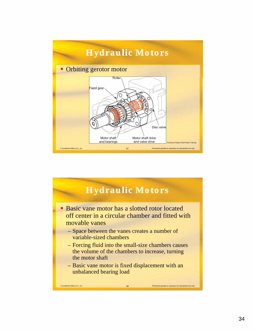
Basic vane motor has a slotted rotor located off center in a circular chamber and fitted withoff center in a circular chamber and fitted with movable vanes– Space between the vanes creates a number of
variable-sized chambers– Forcing fluid into the small-size chambers causes
the volume of the chambers to increase, turning
© Goodheart-Willcox Co., Inc. Permission granted to reproduce for educational use only.68
the volume of the chambers to increase, turning the motor shaft
– Basic vane motor is fixed displacement with an unbalanced bearing load
35
Hydraulic MotorsHydraulic Motors
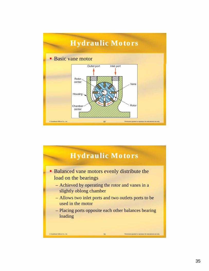
Basic vane motor
© Goodheart-Willcox Co., Inc. Permission granted to reproduce for educational use only.69
Hydraulic MotorsHydraulic Motors
Balanced vane motors evenly distribute the l d th b iload on the bearings– Achieved by operating the rotor and vanes in a
slightly oblong chamber
– Allows two inlet ports and two outlets ports to be used in the motor
© Goodheart-Willcox Co., Inc. Permission granted to reproduce for educational use only.70
– Placing ports opposite each other balances bearing loading
36
Hydraulic MotorsHydraulic Motors
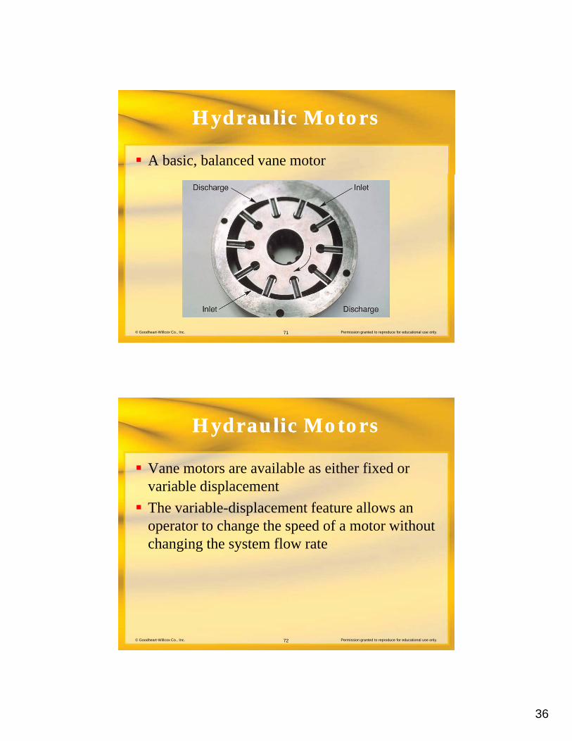
A basic, balanced vane motor
© Goodheart-Willcox Co., Inc. Permission granted to reproduce for educational use only.71
Hydraulic MotorsHydraulic Motors
Vane motors are available as either fixed or i bl di l tvariable displacement
The variable-displacement feature allows an operator to change the speed of a motor without changing the system flow rate
© Goodheart-Willcox Co., Inc. Permission granted to reproduce for educational use only.72
37
Hydraulic MotorsHydraulic Motors
In variable-displacement designs, the chamber i hi h th t d t iin which the rotor and vanes operate is contained in a moveable ring– When the center point of the rotor and ring are
concentric, the displacement is zero
– Moving the ring so the center points are not
© Goodheart-Willcox Co., Inc. Permission granted to reproduce for educational use only.73
concentric increases the motor displacement and changes motor speed
Hydraulic MotorsHydraulic Motors
Piston motors are available having either fixed i bl di l tor variable displacements
In variable-displacement designs, the length of the piston stroke is changed to vary the volume of fluid needed to rotate the motor one revolution
© Goodheart-Willcox Co., Inc. Permission granted to reproduce for educational use only.74
revolution
38
Hydraulic MotorsHydraulic Motors
Two basic classifications of piston motors are i l i t d di l i taxial piston and radial piston
– An axial piston motor has pistons with centerlines parallel to the axis of the output shaft
– A radial piston motor has pistons with centerlines perpendicular to the axis of the output shaft
© Goodheart-Willcox Co., Inc. Permission granted to reproduce for educational use only.75
Hydraulic MotorsHydraulic Motors
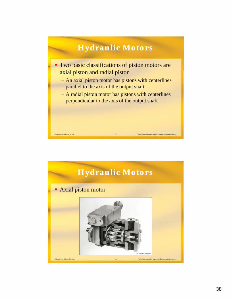
Axial piston motor
© Goodheart-Willcox Co., Inc. Permission granted to reproduce for educational use only.76
The Oilgear Company
39
Hydraulic MotorsHydraulic Motors
Axial piston motors are available in two fi ticonfigurations:
– Inline
– Bent axis
© Goodheart-Willcox Co., Inc. Permission granted to reproduce for educational use only.77
Hydraulic MotorsHydraulic Motors
In an inline piston motor:– Centerline of the barrel is concentric with the
centerline of the power output shaft
– A swash plate transmits force from the pistons to the shaft
© Goodheart-Willcox Co., Inc. Permission granted to reproduce for educational use only.78
40
Hydraulic MotorsHydraulic Motors
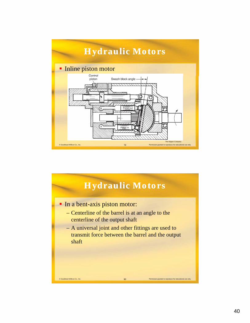
Inline piston motor
© Goodheart-Willcox Co., Inc. Permission granted to reproduce for educational use only.79
The Oilgear Company
Hydraulic MotorsHydraulic Motors
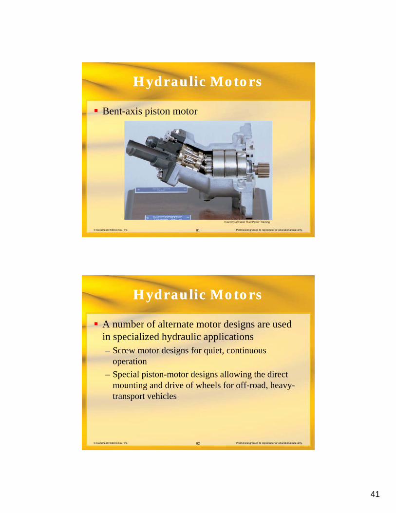
In a bent-axis piston motor:– Centerline of the barrel is at an angle to the
centerline of the output shaft
– A universal joint and other fittings are used to transmit force between the barrel and the output shaft
© Goodheart-Willcox Co., Inc. Permission granted to reproduce for educational use only.80
41
Hydraulic MotorsHydraulic Motors
Bent-axis piston motor
© Goodheart-Willcox Co., Inc. Permission granted to reproduce for educational use only.81
Courtesy of Eaton Fluid Power Training
Hydraulic MotorsHydraulic Motors
A number of alternate motor designs are used i i li d h d li li tiin specialized hydraulic applications– Screw motor designs for quiet, continuous
operation
– Special piston-motor designs allowing the direct mounting and drive of wheels for off-road, heavy-
© Goodheart-Willcox Co., Inc. Permission granted to reproduce for educational use only.82
transport vehicles
42
Hydraulic MotorsHydraulic Motors
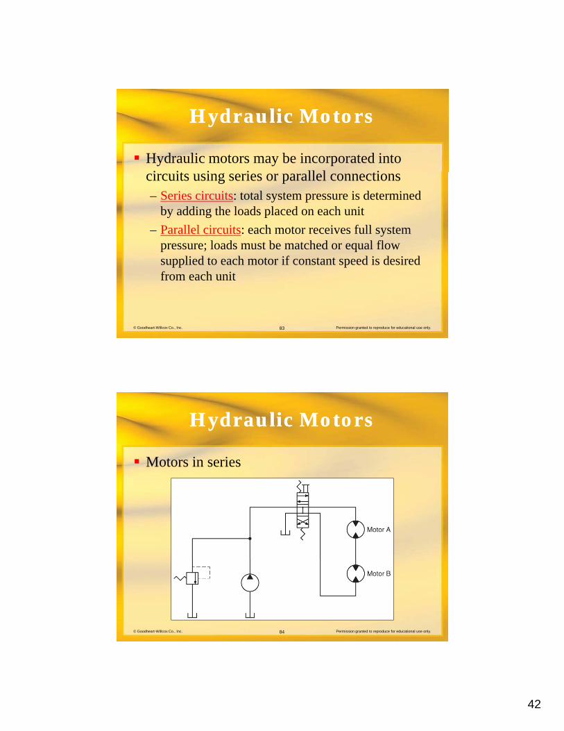
Hydraulic motors may be incorporated into i it i i ll l ticircuits using series or parallel connections– Series circuits: total system pressure is determined
by adding the loads placed on each unit
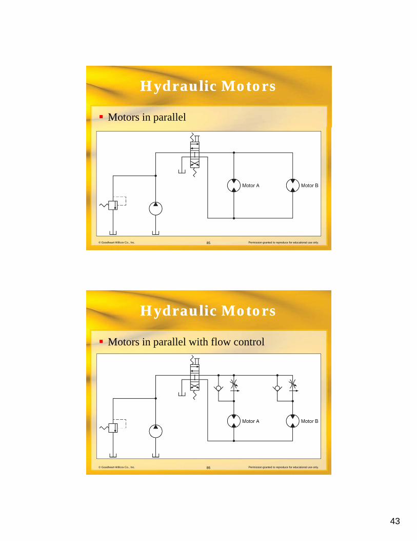
– Parallel circuits: each motor receives full system pressure; loads must be matched or equal flow
© Goodheart-Willcox Co., Inc. Permission granted to reproduce for educational use only.83
supplied to each motor if constant speed is desired from each unit
Hydraulic MotorsHydraulic Motors
Motors in series
© Goodheart-Willcox Co., Inc. Permission granted to reproduce for educational use only.84
43
Hydraulic MotorsHydraulic Motors
Motors in parallel
© Goodheart-Willcox Co., Inc. Permission granted to reproduce for educational use only.85
Hydraulic MotorsHydraulic Motors
Motors in parallel with flow control
© Goodheart-Willcox Co., Inc. Permission granted to reproduce for educational use only.86
44
Hydraulic MotorsHydraulic Motors
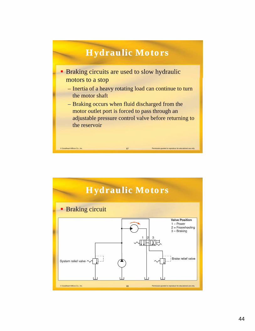
Braking circuits are used to slow hydraulic t t tmotors to a stop
– Inertia of a heavy rotating load can continue to turn the motor shaft
– Braking occurs when fluid discharged from the motor outlet port is forced to pass through an
© Goodheart-Willcox Co., Inc. Permission granted to reproduce for educational use only.87
adjustable pressure control valve before returning to the reservoir
Hydraulic MotorsHydraulic Motors
Braking circuit
© Goodheart-Willcox Co., Inc. Permission granted to reproduce for educational use only.88
45
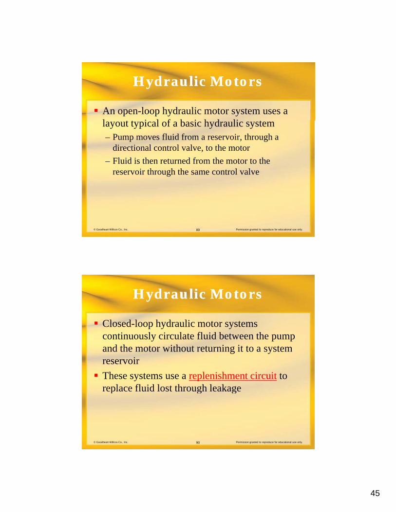
Hydraulic MotorsHydraulic Motors
An open-loop hydraulic motor system uses a l t t i l f b i h d li tlayout typical of a basic hydraulic system– Pump moves fluid from a reservoir, through a
directional control valve, to the motor
– Fluid is then returned from the motor to the reservoir through the same control valve
© Goodheart-Willcox Co., Inc. Permission granted to reproduce for educational use only.89
Hydraulic MotorsHydraulic Motors
Closed-loop hydraulic motor systems ti l i l t fl id b t thcontinuously circulate fluid between the pump
and the motor without returning it to a system reservoir
These systems use a replenishment circuit to replace fluid lost through leakage
© Goodheart-Willcox Co., Inc. Permission granted to reproduce for educational use only.90
replace fluid lost through leakage
46
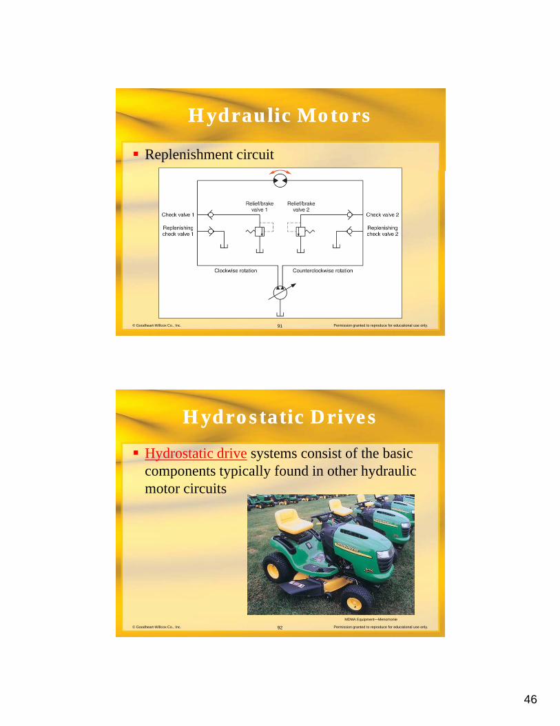
Hydraulic MotorsHydraulic Motors
Replenishment circuit
© Goodheart-Willcox Co., Inc. Permission granted to reproduce for educational use only.91
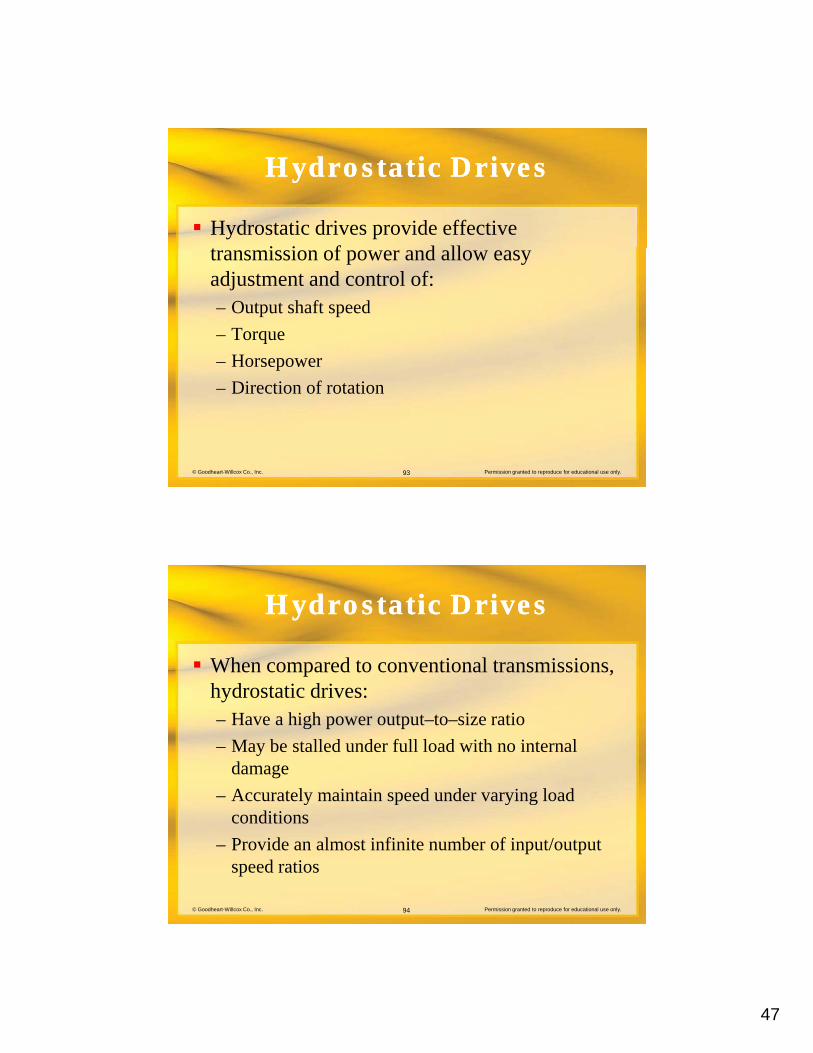
Hydrostatic DrivesHydrostatic Drives
Hydrostatic drive systems consist of the basic components typically found in other hydrauliccomponents typically found in other hydraulic motor circuits
© Goodheart-Willcox Co., Inc. Permission granted to reproduce for educational use only.92
MDMA Equipment—Menomonie
47
Hydrostatic DrivesHydrostatic Drives
Hydrostatic drives provide effective t i i f d lltransmission of power and allow easy adjustment and control of:– Output shaft speed
– Torque
– Horsepower
© Goodheart-Willcox Co., Inc. Permission granted to reproduce for educational use only.93
p
– Direction of rotation
Hydrostatic DrivesHydrostatic Drives
When compared to conventional transmissions, h d t ti d ihydrostatic drives:– Have a high power output–to–size ratio
– May be stalled under full load with no internal damage
– Accurately maintain speed under varying load
© Goodheart-Willcox Co., Inc. Permission granted to reproduce for educational use only.94
y p y gconditions
– Provide an almost infinite number of input/output speed ratios
48
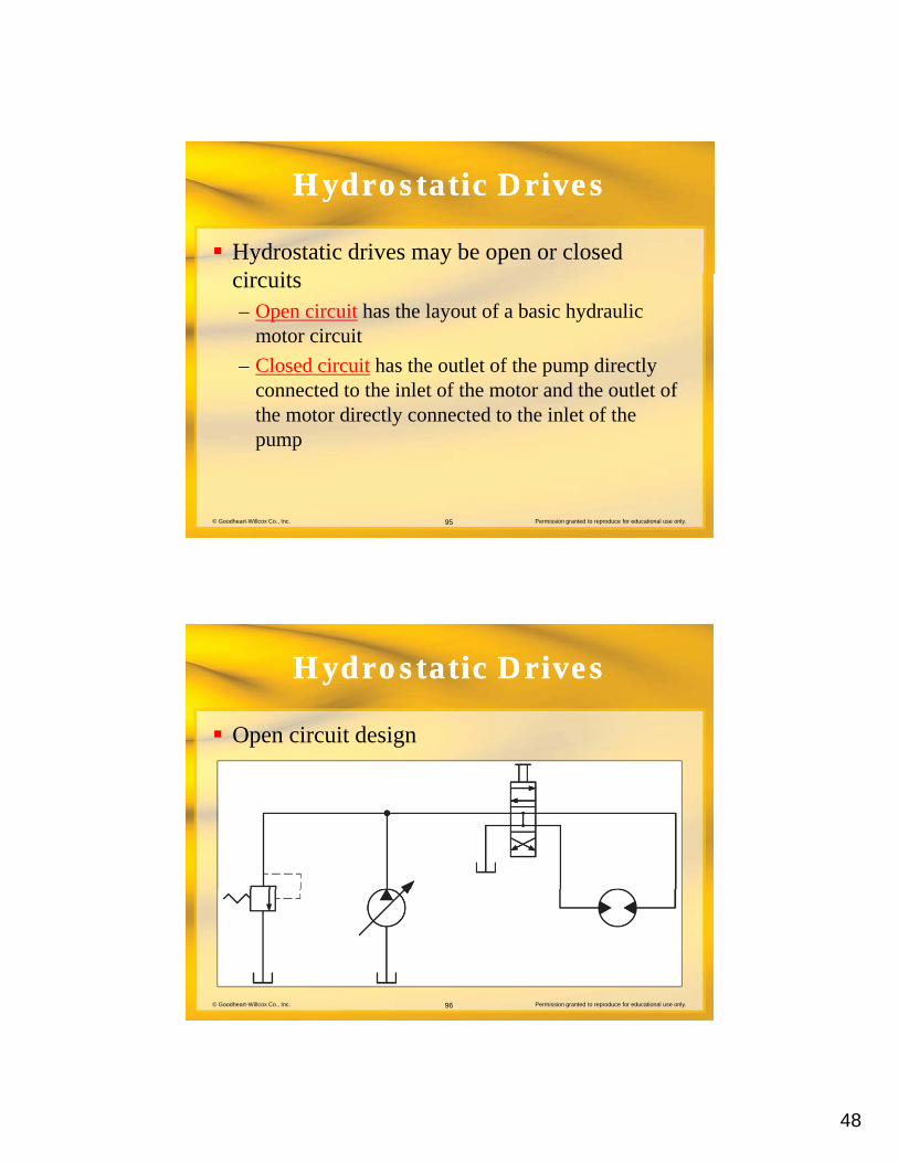
Hydrostatic DrivesHydrostatic Drives
Hydrostatic drives may be open or closed i itcircuits– Open circuit has the layout of a basic hydraulic
motor circuit
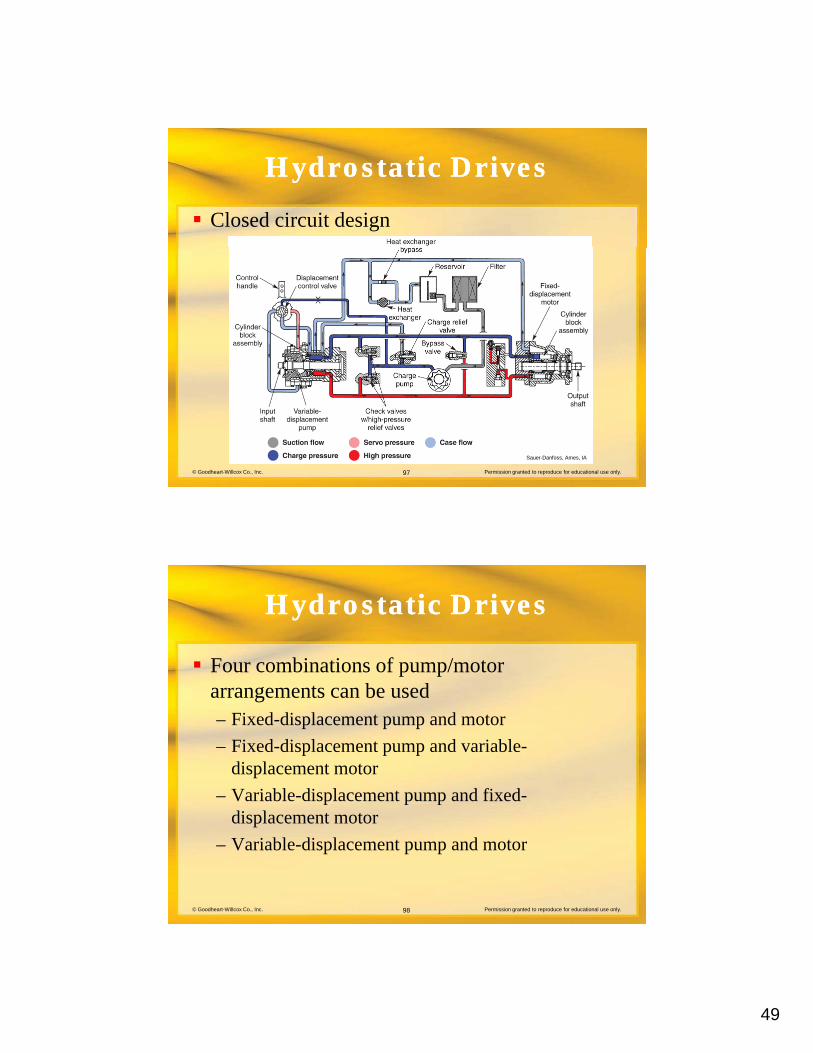
– Closed circuit has the outlet of the pump directly connected to the inlet of the motor and the outlet of
© Goodheart-Willcox Co., Inc. Permission granted to reproduce for educational use only.95
the motor directly connected to the inlet of the pump
Hydrostatic DrivesHydrostatic Drives
Open circuit design
© Goodheart-Willcox Co., Inc. Permission granted to reproduce for educational use only.96
49
Hydrostatic DrivesHydrostatic Drives
Closed circuit design
© Goodheart-Willcox Co., Inc. Permission granted to reproduce for educational use only.97
Sauer-Danfoss, Ames, IA
Hydrostatic DrivesHydrostatic Drives
Four combinations of pump/motor t b darrangements can be used
– Fixed-displacement pump and motor
– Fixed-displacement pump and variable-displacement motor
– Variable-displacement pump and fixed-
© Goodheart-Willcox Co., Inc. Permission granted to reproduce for educational use only.98
p p pdisplacement motor
– Variable-displacement pump and motor
50
Hydrostatic DrivesHydrostatic Drives
Fixed-displacement pump and motor:– Maximum horsepower, torque, and output shaft
speed are fixed
– Pump and motor have fixed displacement, so these characteristics cannot be changed
© Goodheart-Willcox Co., Inc. Permission granted to reproduce for educational use only.99
Hydrostatic DrivesHydrostatic Drives
Fixed-displacement pump and variable-di l t tdisplacement motor:– Maximum horsepower is fixed
– Torque and speed are variable
– Due to use of a relief valve, efficiency is lowered
– Output shaft rotation may be reversed if the pump
© Goodheart-Willcox Co., Inc. Permission granted to reproduce for educational use only.100
Output shaft rotation may be reversed if the pump is reversible
51
Hydrostatic DrivesHydrostatic Drives
Variable-displacement pump and fixed-di l t tdisplacement motor:– Torque output is fixed
– Horsepower and output shaft speed are variable
– Output shaft rotation may be reversed if pump is reversible
© Goodheart-Willcox Co., Inc. Permission granted to reproduce for educational use only.101
Hydrostatic DrivesHydrostatic Drives
Variable-displacement pump and motor:– Horsepower, torque, output shaft speed are variable
– Output shaft direction is reversible
– Most versatile of the four pump/motor combinations
© Goodheart-Willcox Co., Inc. Permission granted to reproduce for educational use only.102
52
Hydrostatic DrivesHydrostatic Drives
Hydrostatic drives are typically considered h d t ti t i i h b th thhydrostatic transmissions when both the pump and motor have variable displacement
This combination allows manual or automatic control of torque, speed, and power output
© Goodheart-Willcox Co., Inc. Permission granted to reproduce for educational use only.103
Hydrostatic DrivesHydrostatic Drives
Two different general techniques are used Two different general techniques are used in the construction of hydrostatic transmissions– Integral
– Nonintegral
© Goodheart-Willcox Co., Inc. Permission granted to reproduce for educational use only.104
53
Hydrostatic DrivesHydrostatic Drives
Integral construction combines all of the t i i t i t i l h itransmission parts into a single housing
Nonintegral construction involves separate pump, motor, and accessories connected by hoses or tube assemblies
© Goodheart-Willcox Co., Inc. Permission granted to reproduce for educational use only.105
Review QuestionReview Question
A(n) _____ cylinder can exert force during b th th t i d t ti t kboth the extension and retraction strokes.
double-acting
© Goodheart-Willcox Co., Inc. Permission granted to reproduce for educational use only.106
54
Review QuestionReview Question
A(n) _____ is the system component that t fl id d fl i t liconverts fluid pressure and flow into linear
force and movement.
hydraulic cylinder
© Goodheart-Willcox Co., Inc. Permission granted to reproduce for educational use only.107
Review QuestionReview Question
List the three basic configurations used to t li d t i tmount cylinders to equipment.
A. Fixed centerline, B. fixed non-centerline, and C. pivoting centerline.
© Goodheart-Willcox Co., Inc. Permission granted to reproduce for educational use only.108
55
Review QuestionReview Question
The three conceptual component groups that make up any hydraulic motor are:y yA. Rotor, vanes, and eccentric.B. Housing, rotating internal parts, and power output shaft.C. Housing, reciprocating internal parts, and power input shaft.D. Rotating internal parts, power input shaft, and power output
shaft.
© Goodheart-Willcox Co., Inc. Permission granted to reproduce for educational use only.109
B. Housing, rotating internal parts, and power output shaft.
Review QuestionReview Question
To vary the displacement of a vane motor, a bl i d t h th i f thmovable _____ is used to change the size of the
pumping chambers.
cam ring
© Goodheart-Willcox Co., Inc. Permission granted to reproduce for educational use only.110
56
Review QuestionReview Question
List the four possible pump/motor arrangements th t b d ith h d t ti tthat may be used with a hydrostatic system.
A. Both pump and motor have fixed displacements, B. pump has a fixed displacement and the motor a variable displacement C pump has a variable
© Goodheart-Willcox Co., Inc. Permission granted to reproduce for educational use only.111
variable displacement, C. pump has a variable displacement and the motor a fixed displacement, and D. both pump and motor have variable displacement.
Review QuestionReview Question
During retraction, what is the effective area of th i t f d bl ti li d ?the piston of a double-acting cylinder?
The cross-sectional area of the piston minus the cross-sectional area of the rod.
© Goodheart-Willcox Co., Inc. Permission granted to reproduce for educational use only.112
57
Review QuestionReview Question
A cylinder that has externally mounted metal d h ldi th d th b l i ll drods holding the ends on the barrel is called
a(n) _____ cylinder.
tie-rod
© Goodheart-Willcox Co., Inc. Permission granted to reproduce for educational use only.113
GlossaryGlossary
Barrel– The component containing the cylinders of an
axial piston hydraulic pump.
Clevis mount– A cylinder rod and cap mounting configuration
involving a C-shaped casting and a mounting pin
© Goodheart-Willcox Co., Inc. Permission granted to reproduce for educational use only.114
g p g g pthat allows the cylinder to pivot during extension and retraction.
58
GlossaryGlossary
Closed circuit– A hydraulic circuit design in which pump output is
returned directly to the pump inlet after passing through a hydraulic motor. The design is commonly used with hydrostatic drive systems.
© Goodheart-Willcox Co., Inc. Permission granted to reproduce for educational use only.115
GlossaryGlossary
CushioningA d i f t i fl id li d th t– A design feature in fluid power cylinders that reduces fluid flow near the end of the extension or retraction stroke to decelerate piston movement, which avoids both noise and component damage.
Double-acting cylinder– Cylinders that may be powered both on the
© Goodheart-Willcox Co., Inc. Permission granted to reproduce for educational use only.116
Cylinders that may be powered both on the extension and retraction strokes.
59
GlossaryGlossary
Effective piston area– The area of a piston that contributes to the force
generated by system pressure. For example, the effective area of a cylinder piston during retraction is the area of the piston minus the cross-sectional area of the piston rod.
© Goodheart-Willcox Co., Inc. Permission granted to reproduce for educational use only.117
GlossaryGlossary
Fixed-centerline mount– A cylinder-mounting design in which the load
carried by the cylinder rod and piston is supported at the centerline of the cylinder barrel, which is fixed to a machine member.
© Goodheart-Willcox Co., Inc. Permission granted to reproduce for educational use only.118
60
GlossaryGlossary
Head– The height of a column of water or other liquid
necessary to develop a stated pressure.
Hydrostatic drive– A fluid power drive system using a hydraulic pump
and motor to transmit the power of a prime mover
© Goodheart-Willcox Co., Inc. Permission granted to reproduce for educational use only.119
p pto the input of a machine. Available in either open-or closed-circuit designs.
GlossaryGlossary
Limited-rotation actuatorA t t d i th t i il d– An actuator design that primarily produces rotational movement of one revolution or less. Various designs are available using a rack and pinion, vane, or helical shaft.
Mill cylinder– A hydraulic cylinder constructed of heavy steel for
© Goodheart-Willcox Co., Inc. Permission granted to reproduce for educational use only.120
A hydraulic cylinder constructed of heavy steel for use in industries such as foundries and steel mills.
61
GlossaryGlossary
Open circuit– A hydraulic circuit that uses the layout of a basic
hydraulic motor circuit with a directional control valve to control motor direction and a reservoir to hold surplus fluid.
© Goodheart-Willcox Co., Inc. Permission granted to reproduce for educational use only.121
GlossaryGlossary
Orbiting gerotor motor– A variation of the gerotor motor that uses the
internal-toothed gear of the gerotor set as a fixed gear. The external-toothed gear orbits following the internal-toothed gear. This produces higher torque/lower speed output.
© Goodheart-Willcox Co., Inc. Permission granted to reproduce for educational use only.122
62
GlossaryGlossary
Parallel circuit– An electrical or fluid power circuit that
simultaneously provides multiple paths for the current or fluid to follow as it moves through a circuit.
© Goodheart-Willcox Co., Inc. Permission granted to reproduce for educational use only.123
GlossaryGlossary
Pivoting-centerline mount– A clevis or trunnion mounting that allows the
cylinder to follow an arc as it powers a machine member. The load remains concentrated on the centerline of the cylinder.
© Goodheart-Willcox Co., Inc. Permission granted to reproduce for educational use only.124
63
GlossaryGlossary
Replenishment circuit– A circuit used with closed-loop hydraulic systems
that provides makeup fluid to replace any fluid lost from leakage during system operation.
Series circuit– An electrical or fluid power circuit that provides
© Goodheart-Willcox Co., Inc. Permission granted to reproduce for educational use only.125
p ponly one path for the current or fluid to follow as it moves through the circuit.
GlossaryGlossary
Single-acting cylinder– A cylinder design that exerts force only on
extension or retraction and depends on some outside force to complete the second movement.
© Goodheart-Willcox Co., Inc. Permission granted to reproduce for educational use only.126
64
GlossaryGlossary
Telescoping cylinder– A linear actuator constructed of several nested tubes
that can extend a distance equal to several times the actuator’s retracted length.
Threaded-end cylinder– A linear actuator design in which the cap and head
© Goodheart-Willcox Co., Inc. Permission granted to reproduce for educational use only.127
g pare attached to the barrel of the cylinder by threads.
GlossaryGlossary
Tie-rod cylinderA linear actuator design in which the cap and head– A linear actuator design in which the cap and head components are secured to the barrel of the cylinder by external tie rods that run between those components.
© Goodheart-Willcox Co., Inc. Permission granted to reproduce for educational use only.128
65
GlossaryGlossary
Trunnion mountA cylinder mounting method that places fittings on– A cylinder mounting method that places fittings on the sides of cylinders, allowing the cylinder to pivot as it extends and retracts to move a machine member.
© Goodheart-Willcox Co., Inc. Permission granted to reproduce for educational use only.129