chapter 8 metallurgical studies on stainless steel...
TRANSCRIPT

157
CHAPTER 8
METALLURGICAL STUDIES ON STAINLESS STEEL
CLADDINGS
8.1 INTRODUCTION
Successful cladding requires thorough understanding of base metal
and the clad metal. In this investigation, AISI 316 L austenitic stainless steel
overlays deposited on carbon steel plates at low, medium, high and optimum
weld heat input conditions by the PTAW process are characterized with the
help of microstructural analysis. Due to the difference in melting temperature
range between the carbon steel substrate and the stainless steel clad metal the
dilution of the clad bead could be significantly affected. When dilution is
altered, it will influence the resulting microhardness and the microstructure of
the claddings. Therefore, a metallurgical study is carried out across the
various zones of the cladding. Microhardness survey was conducted to
confirm the different phases present and colour metallography was used to
reveal microstructures at different zones of the claddings. Since the weld
metal ferrite content can influence a wide range of properties which includes
corrosion resistance and resistance to hot cracking, the amount of delta ferrite
present in the claddings is measured and the effect of heat input on ferrite
content is presented.

158
8.2 EXPERIMENTAL PROCEDURE
8.2.1 Measurement of microhardness in stainless steel claddings
Four test specimens were prepared from the overlay plate cladded at
different heat input conditions as well as at optimum dilution condition for
carrying out the metallographic characterisation of the claddings. Standard
metallurgical procedures were followed to prepare specimens obtained from
the claddings. The samples were etched with 10 % oxalic acid solution for
revealing the different zones of the weldments such as clad metal, fusion zone
and heat affected zone. The base metal zone is etched with a 2 % nital to
facilitate microhardness studies. The microhardness measurement was carried
out as per ASTM E 384 Standard Test Method by using a MITUTOYO
(Model: M11, Japan) microhardness tester, as shown in Figure 8.1.
Figure 8.1 Microhardness testing machine

159
The microhardness is measured at very close distances across the
bead profile along its centreline perpendicular to the direction of welding.
This is carried out across the four different zones namely the Base Metal
(BM) zone, Heat Affected Zone (HAZ), Fusion Boundary Zone (FBZ) and
the Weld Metal (WM) zone. The measurements on each specimen was carried
out initially from the base metal and progressed towards various zones along
the centreline of the weld bead profile perpendicular to the direction of
welding. A Vickers indenter with a 100 gram load was used with a loading
time of 20 seconds to make indentation on the specimens. The measurements
are taken on the two sides of the specimen to assess the different phases
present in the microstructural constituents of the claddings.
8.2.2 Measurement of ferrite number in stainless steel claddings
Stainless steel cladding usually contain delta ferrite, which is
expressed in terms of FN. The Ferritescope utilizes the eddy current to
measure the magnetic properties which are calibrated in terms of ferrite
number. The ferrite number measurement is carried out using a Fischer
feritescope (Model: FS-311), as shown in Figure 8.2. The feritescope is
calibrated with standard specimens before measuring the ferrite number.
Figure 8.2 Feritescope used for Ferrite number measurements
160
The four test specimens were prepared from the overlay plate
cladded at different heat input conditions as well as at optimum dilution
condition for carrying out the ferrite number measurement of the claddings.
The top surface of cladded specimen is ground and polished to a depth of
0.5mm for ferrite measurement. The ferrite number is measured on the top
surface of the ground cladded plates at different locations as shown in Figure-
8.3.
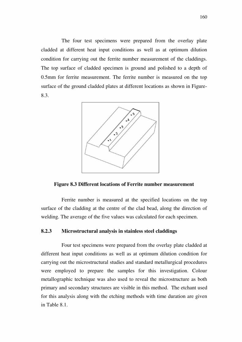
Figure 8.3 Different locations of Ferrite number measurement
Ferrite number is measured at the specified locations on the top
surface of the cladding at the centre of the clad bead, along the direction of
welding. The average of the five values was calculated for each specimen.
8.2.3 Microstructural analysis in stainless steel claddings
Four test specimens were prepared from the overlay plate cladded at
different heat input conditions as well as at optimum dilution condition for
carrying out the microstructural studies and standard metallurgical procedures
were employed to prepare the samples for this investigation. Colour
metallographic technique was also used to reveal the microstructure as both
primary and secondary structures are visible in this method. The etchant used
for this analysis along with the etching methods with time duration are given
in Table 8.1.

161
The microstructures were taken by using a NEOPHOT
(Model: NEO-32), an optical metallurgical microscope with an inbuilt camera
to photograph the microstructures with different magnifications. The
micrographs were taken for the claddings deposited at low, medium, high and
optimum heat input conditions and are taken in the section transverse to the
welding direction.
Table 8.1 Details of etchants used for base and clad metals
Sl
noMaterial Etchant Description
Etching
duration,
seconds
1 Structural
steel
Etchant I 2% of Nital at room temperature
(applied on the surface by a cotton
swab)
30-35
2 Structural
steel
Etchant II 50 ml cold-saturated (in distilled water)
sodium thiosulphate solution and 1 gram
potassium metabisulphite
(specimen is immersed and steered)
30-90
3 Stainless
steel
Etchant A
(for Black &
White images)
10% Oxalic Acid (electro etched at
6 Volts and 1 Amps/cm2) 90 -120
4 Stainless
steel
Etchant B
(for Colour
images)
20 gram Ammonium bi-fluoride
and 0.5 gram Potassium meta-
bisulphite diluted in 100ml distilled
water (specimen is immersed and
steered)
30 -60
8.3 RESULTS AND DISCUSSION
8.3.1 Measurement of microhardness in stainless steel claddings
The microhardness survey was conducted on the claddings
deposited at different heat input conditions and at optimum heat input
162
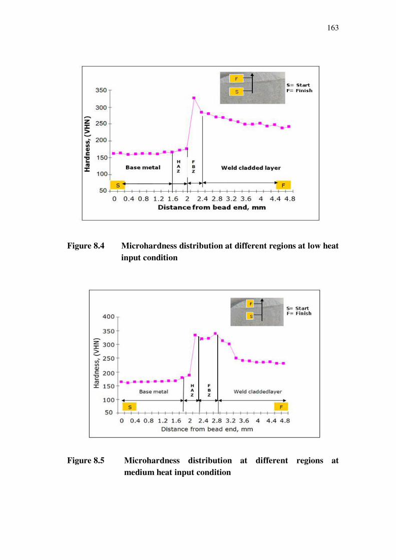
condition by the PTAW process. For each specimen, measurements were
taken on both sides and the mean value is calculated. The results of the
microhardness survey are presented from Figures 8.4 to 8.7.
There is no appreciable change in the micro hardness of the base
metal region in all the claddings which confirm that the properties of the base
metal are retained. It is found that the HAZ increased with increase in heat
input and this might be due to the formation of bainitic structure in the HAZ.
It is evident that the microhardness in the HAZ of the claddings deposited at
low and optimum heat input did not increase which gave an interpretation that
they possesses higher ductility. The increase in the microhardness of the
claddings deposited at medium heat conditions is moderate but in the case of
high heat input specimen it is fairly high.
In the Fusion boundary zone (FBZ), the increase in microhardness
of the claddings deposited at high heat input condition is the hardness
suddenly increased to a higher value and then drops marginally. This sudden
increase in hardness might be due to the formation of the martensitic structure
in the FBZ and the indentations are incorporated in Figure 8.6. In the overlay
region, the microhardness decreased gradually in all the claddings and an
appreciable reduction in microhardness is observed in the claddings deposited
at high heat input condition.
163
Figure 8.4 Microhardness distribution at different regions at low heat
input condition
Figure 8.5 Microhardness distribution at different regions at
medium heat input condition

164
Figure 8.6 Microhardness distribution at different regions at high heat
input condition
Figure 8.7 Microhardness distribution at different regions at
optimum heat input condition

165
8.3.2 Measurement of Ferrite number in stainless steel claddings
The ferrite number is measured on the surface of the claddings
deposited at different heat inputs and optimum heat input conditions. These
measurements were taken on five different locations on each cladding and
presented in Table 8.2.
Table 8.2 Variation of ferrite number on the surface of the cladding
Sl
NoLocations
HEAT INPUT
Low
(4.10 KJ/mm)
Medium
(5.54 KJ/mm)
High
(6.81 KJ/mm)
Optimum
(4.31 KJ/mm)
1 1 11.8 6.8 4.2 5.2
2 2 10.3 6.3 5.1 6.4
3 3 10.5 7.3 4.8 5.8
4 4 12.8 8.8 4.9 6.3
5 5 11.5 8.5 5.3 6.1
Average 11.38 7.54 4.8 5.96
Higher values of ferrite number were observed in the cladding
deposited at low heat input condition. Also lower ferrite number was noticed
in the cladding deposited at high heat input condition which has enabled the
formation of more austenitic phases than the ferrite.
8.3.3 Microstructural analysis in stainless steel cladding
A large number of optical micrographs were obtained at different
magnifications on the cross sections of claddings deposited at different heat
inputs and at optimum heat input condition are presented in Figures 8.8 –
8.14. The photomicrographs are taken along the section which was
perpendicular to cladding direction.

166
Figure 8.8 shows the microstructures of base metal etched with
Etchants I and II respectively for obtaining black and white and colour
photomicrographs at a magnification of X200. Both the microstructures
clearly reveal the presence of ferrite phases and pearlite phases. Presence of
blue coloured pearlite in brown coloured ferrite matrix is visible in the colour
photomicrograph.
ETCHANT-I / X200 ETCHANT-II / X 200
Figure 8.8 Microstructure of the base metal
The optical photomicrographs obtained at 200 X and 400 X from the
cladding deposited at low heat input condition and etched with the etchants A
and B are shown in Figure 8.9. It is evident from the figure that the
microstructure represents austenite matrix containing little amount of delta
ferrite. The coloured microstructure reveals the matrix of austenite (bluish and
brownish) and delta ferrite (white) phases. The presence of columnar dendrite
structure indicates faster cooling rate due to low heat input condition. The
primary structures of the austenitic regions are blue and the final solidification
regions are brown in colour.

167
ETCHANT-A / X200 ETCHANT-B / X 400
Figure 8.9 Microstructure of the cladding deposited at low heat
input (4.10 KJ/mm) condition
Figure 8.10 depicts the photomicrograph obtained from the cladding
deposited at medium heat input condition and etched with the etchants A and
B. It is evident from the microstructure that the presence of vermicular
structure is visible in the clad layer. Also, the microstructure at a
magnification of 400 X, with etchant B reveals the matrix of austenite
(greenish blue / bluish) and delta ferrite (pale yellow). The primary structures
of the austenitic regions are greenish blue and the final solidification regions
are bluish in colour.

168
ETCHANT-A / X200 ETCHANT-B / X 400
Figure 8.10 Microstructure of the cladding deposited at medium heat
input (5.54 KJ/mm) condition
The photomicrographs of the cladding deposited at high heat input
condition and etched with the etchants A and B are shown in Figure 8.11.
ETCHANT-A / X200 ETCHANT-B / X 400
Figure 8.11 Microstructure of the cladding deposited at high heat
input (6.81 KJ/mm) condition

169
It is evident from the figure, that the presence of vermicular
morphology of ferrite in the austenite matrix is visible in the clad layer. The
colour microstructure obtained at a magnification of 400 X reveals the
presence of ferrite (white) and austenite (blue) matrix. Coarser austenite
grains are found in the microstructure which may be due to higher heat input
in the cladding. The blue color cellular crystals show a slightly wavy surface,
indicating the beginning of dendritic crystal formation and the presence of
delta ferrite is clearly seen in small white patches.
The optical photomicrograph obtained from the cladding deposited
at optimum heat input condition and etched with the etchants A and B are
presented in Figure 8.12. It resembles to the microstructures obtained from
the cladding deposited at low heat input condition with a slightly coarser
austenite grains.
ETCHANT-A / X200 ETCHANT-B / X 400
Figure 8.12 Microstructure of the cladding deposited at optimum heat
input (4.31 KJ/mm) condition
170
8.6 SUMMARY
The stainless steel claddings were characterised to evaluate the
properties influencing their corrosion and wear resistance. A significant
increase in the hardness is found in the cladding deposited at high heat input
condition. Higher ferrite content was found in the cladding deposited at low
heat input condition. The microstructure of the cladding produced at optimum
heat input condition has vermicular ferrite in the austenite matrix.