chapter 8 fuction block - takacszoltan.eu
TRANSCRIPT

Chapter 8 Fuction Block
8-1
Chapter 8 Fuction Block
8.1 Introduction
8.1.1 Introduction
Function Block is used to communicate between Ethernet communication module of one’s own station and Ethernet communication of destinationstation’s or between Ethernet communications of one’s own stations using TCP/IP or UDP/IP. The communication using Function Block consists of two two ways of communication: Single communication method using only Function Block to communicate independently, and user-defined communication methodusing frame editor. This chapter describes the kind of Function Block provided to a user and its use. The following displays program editing order using Function Block.
Parameter/Frame Editing
1 Writing after frame editor editing
Project
2 Generating or Opening Program
Writing Program
3 Writing Program with LD / IL
Compile/Make
4 Compile or Make
On-line Connection
5 Connection
On-line/Writing
6 ¤ Parameter and
Program
On-line/Mode Switchover
7 RUN Operation Mode
Set the Contents of 1 to 7 to DestinationStation.
Downloading into Enetmodule after editing IP Address, HS_LINK, Station Number, Subnet Mask, Gateway address, Frame, etc using Editor Frame Editor (when using Frame, switch CPU to Stop mode, then switch power on again.)
Writing project and program on GMWIN screen or opening the existing project, program.
Confirm I/P address of communication module of ones station and parter station HS_LINK station number, slot position, etc. and write a program for emergency using proper flag.
Confirm action status of program using monitoring function when it is started. If an error ocurrs, grasp the cause of the error using STATUS value of Function Block.
Chapter 8 Fuction Block
8-2
8.1.2 Kind and Use of Function Block
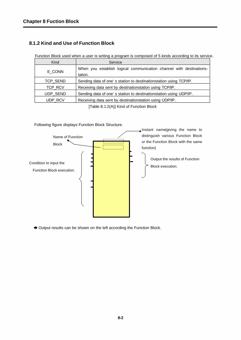
Function Block used when a user is writing a program is composed of 5 kinds according to its service.
Kind Service
E_CONN When you establish logical communication channel with destinations-tation.
TCP_SEND Sending data of one’s station to destinationstation using TCP/IP.
TCP_RCV Receiving data sent by destinationstation using TCP/IP.
UDP_SEND Sending data of one’s station to destinationstation using UDP/IP.
UDP_RCV Receiving data sent by destinationstation using UDP/IP.
[Table 8.1.2(A)] Kind of Function Block
Following figure displays Function Block Structure.
è Output results can be shown on the left according the Function Block.
Output the results of Function
Block execution.
Condition to input the
Function Block execution.
Instant name(giving the name to
distinguish various Function Block
or the Function Block with the same
function)
Name of Function
Block

Chapter 8 Fuction Block
8-3
Common I/O of each Function Block is here described.
REQ :
Used for start condition of Function Block except E_CONN Function Block. The Function Block is started at positive edge of ‘0’ to ‘1’, and once it is started, it will be not influenced before it receives response from destinationstation. That is, as far as it bit of NDR(DONE) or ERR is not set, the Function Block is not influenced, and it restarts in the next scan after the bit of NDR or ERR is set.
EN :
When level is ‘1’, the Function Block starts, and when service is being done, ‘1’ must be maintained. (It applies to only to E_CONN Function Block:BOOL type) After the service is done, ‘1’ must be continuously maintained. If EN bit keeps ‘1’ after ERR bit is ‘On’, Function Block will ask for service for communication channel establishment in the next scan again. If value is changed from ‘1’ into ‘0’, it will ask that established channel should be normally resolved.
NET_NO:
It specifies communication module to perform main Function Block out of the communication modules installed at elementary base. It is namely the slot positon installed by communication at the elementary base, and by slot position of elementary base, slot number ‘0’ is next to CPU, and increases ‘1’ by ‘1’. (Available area : 0 ~ 7 )
POWER CPU NET_NO NET_NO NET_NO NET_NO ...... #0 #1 #2 #3
IP_ADDR: IP address of communication module of of destinationstation or one’s station. It specifies IP necessary address when communicating or establishing a channel. It needs IP address of destinationstation or one’s station according to Function Block. (Please refer to each Function Block).
Example) ‘150.150.42.150’
Input

Chapter 8 Fuction Block
8-4
D_PORT: Port number of destinationstation’s communicatin module (Setting between
h’400 - h’7fff).
S_PORT: Port number of communicaton module of one’s station (Setting between h’400 - h’7fff.).
CH_NO: Channel number to be established (Selected by user.)
Able to select at least 16 chnannels from channel number ‘0’ up to ‘16’, Unable to use the same channel number in two Function Block within a program.
ARR_CNT/DATA_LEN : Data volume to be sent and received. Volume of transferred frame can be up to1,400 bytes, but for redundant system of GMR, the volume of transferred frame is limited to 120 bytes.
NDR : After Function Block is started, when you receive data normally, it turns ‘On’ and then it turns ‘Off’ when the next Function Block will be started.
ERR :
After Function Block is started, when an error occurs, it turns ‘On’, when the next Function Block will be started. If an error occurs, data are not received. (For error code, refer to ‘ A3. Error Code’ of appendix).
STATUS :
After Function Block is started, when an error occurs, and ERR turns ‘On’, It displays detail code value of the error. It keeps its value till the next Function Block is started.
Output

Chapter 8 Fuction Block
8-5
E_CONN
Product GMR GM1 GM2 GM3 GM4 GM5 GM6 GM7
Applicability l l l l l
Function Block Dexcription
Input
EN : When level is ‘1’, Function Block is executed. It
must keep ‘1’ in service.
NET_NO : Slot number (0 to 7), in which
communication module of one’s station is
installed, to which this Function Block is
transferred.
IP_ADDR : When establishing a channel, It uses IP
address of destination station with TCP_ACTIVE,
and uses IP address of one’s station with
TCP_PASSIVE.
SD_PORT : When establishing a channel, it uses
port of partne station with TCP_ACTIVE, and it
uses port of one’s station with TCP_PASSIVE.
METHOD: When establishing a channel, It
determines system to activate with TCP or
UDP, Clientor Server. (See the description
below)
CH_NO : Channel number to be established. ( 0~15 )
Output
NDR : It turns ‘On’ at normal channel establishment.
ERR : It turns ’On’ at error occurance after Function
Block is executed.
STATUS : It is detail code value of error when it occurs.
CH_EN : Results of channel establishment.
It turns ‘On’ at normal channel
establishment.
Function Block used when you establish a logical communication channel with destinationstation. The method to establish the logical channel in Ethernet communication consists of 5 kinds. their setting method according to each system service is as follows (IP_ADDR, SD_PORT, METHOD).
IP_ADDR
CH_EN
STATUS
ERR
NDR
CH_NO
METHOD
SD_PORT
NET_NO
STRING
STRING
BOOL
USINT
BOOL
BOOL
USINT
USINT
UINT
BOOL EN
E_CONN
Establishing Logical Communication Chahnnel with DestinationStation

Chapter 8 Fuction Block
8-6
1) TCP_ACTIVE
Destination station’s port (Dest Port) + Destination station IP address (Dest IP_ADDR). A channel to use TCP/IP with, and it specifies destination station of communication. When communicating with destination station, one’s station is activating as ‘Client’.
GLOFA 이더넷 모듈(자국) MMI 기기(PC등)GLOFA 이더넷 모듈(타국)
또는 타사 이더넷 모듈
상대국에 데이터 요구
응답
Server
2) TCP_PASSIVE
One’s station (Source Port) + IP address of one’s station (Source IP_ADDR). A channel to use TCP/IP with, and it is established for the station that demands its establishment most early. It also means that one’s station is activating with ‘Server’ when communicating with the specified destination station.
GLOFA 이더넷 모듈(자국) MMI 기기(PC등)GLOFA 이더넷 모듈(타국)또는 타사 이더넷 모듈
상대국에서 데이터 요구
응답
Client
3) TCP_SELECT
Port of One’s Station (Source Port) + IP Address of Destination Station (Dest IP_ADDR) (It does not exist in the standards) A kind of TCP_PASSIVE. The channel is established for only destination station specifiedby a user. One’s station is activating with ‘Server’ when communicating with the specified destination station.
4) UDP_ACTIVE
Port of One’s Station (Source Port) + IP Address of One’s station (Source IP_ADDR) A channel to use UDP/IP with. It opens only ‘Socket’. One’s station is activating with ‘Client’ when communicating with the specified destination station. (It actually has no relation with the channel)
Request Data for Destination station
GLOFA Ethernet module GLOFA Ethernet module/ Other company ethernet
Response
MMI(like a PC)
GLOFA Ethernet module Self Station
Request Data for Destination station
Response
GLOFA Ethernet module/ Other company ethernet
MMI(like a PC)

Chapter 8 Fuction Block
8-7
5) UDP_PASSIVE
Port of one’s Station (Source Port) + IP Address of One’s Station (Source IP_ADDR)A channel to use UDP/IP with. It binds only ‘Socket’. One’s station is activating with ‘Server’ when communicating with the specified destination station. (It actually has no relation with the channel)
Remark
Note1) ‘PASSIVE(SELECT) OPEN’ must be started earlier than ‘ACTIVE OPEN’.UDP_ACTIVE, UDP_PASSIVE connects internally only with ’Socket’ open without establishing channel through service.
Therefore, you, as a user’ should establish a suitable channel for communication characteristics according to the kinds of logical channel establisment. The channel establishment is done value of METHOD during Function Block input.
METHOD : ‘XXX_YYY(or ‘XXX_YYY_TTT’) - (Within 16 letters : String)
XXX : shows name of group set by frame editor. YYY : Kind of channel establishment. There are 5 kinds: TCPACT, TCPPAS, TCPSEL, UDPACT, UDPPAS. TTT : RX/TX latency time for channel release. (0~FF seconds). It cuts the connection there is no response from partner within the fixed time by force. (In case of TCPPAS)
è Using ‘UNFMT’ in XXX : Used to communicate without using frame editor when
performing data TX/RX. It sends and receives data without changing Function Block data set by a user after Ethernet communication connection. Therefore, if you bind channel in form of ‘UNFMT_YYY’ in METHOD input of E_CONN, You must specify ‘_UDATA_SEND’ (TX) or ‘_UDATA_RCV’ (RX) in ‘FRAME’ within TCP_SEND(UDP_SEND) or TCP_RCV(UDP_RCV) Function Block. Even after that, you can use it.

Chapter 8 Fuction Block
8-8
n A Program Example : When demanding connection with TCP ACTIVE from destination
station.
It is a case in which you demand connection from destination station (GLOFA) with 165.244.149.190, as its IP address and 5000 as its port number of its Enet module when Enet module of one’s station is installed in number ‘0’ slot. In this case, it uses number ‘1’ channel.
L D I L
LD 1 ST CON CAL E_CONN CON_ACT EN:= CON NET_NO:= 0 IP_ADDR:.. ‘165.244.149.190’ SD_PORT:.. 5000 METHOD:= ‘GLOFA_TCPACT’ CH_NO:= 1
If ‘CON’ contact turns ‘On’ as Function Block condition, it demands connection with number’1’ channel among 16 channel of one’s station and port number 5000 of destination station. In this case, it is performed through a TCPACT method (METHOD), in which destination station sends data on demand of one’s station. If destination station responses to the connection demand of one’s station, the connection is done between two stations. In this case, it shows now results through ‘CH_EN’ output. You can now communicate this bit ,‘TCP_SEND’,’TCP_RCV’, ’UDP_SEND’,’UDP_RCV’, in ‘Enable’ concition.
CON_ACT
CON
IP_ADDR
CH_EN
STATUS
ERR
NDR
CH_NO
METHOD
SD_PORT
NET_NO
‘GLOFA_TCPACT
‘165.244.149.19
CH_EN
ERR
0
1
5000
EN
E_CONN ERR

Chapter 8 Fuction Block
8-9
TCP_SEND
Product GMR GM1 GM2 GM3 GM4 GM5 GM6 GM7
Applicability l l l l l
Fundtion Block Destination
Input
REQ : When it is at positive edge (0→1), Function Block is
executed.
NET_NO : Slot number (0 to 7), in which communication
module of one’s station is installed, to which this
Function Block is transferred.
CH_NO : Channel Number edited in E_CONN Function
Block.
FRAME : Frame to be sent (distinguished with capital/small
letter).
It uses the same name used in Frame Editor.
ARR-CNT : Number of data to be sent. Number of data type
equivalent to ‘DATA.
DATA : An area saving TX data. Uses ‘ARRAY’.
Output
NDR : It turns ‘On’ at normal service.
ERR : It turns ’On’ at error occurance after Function Block is
executed.
STATUS : It is detail code value of error when it occurs.
It is used to send data of one’s station to destination station using TCP/IP. It sends them to destination station installed with ‘CH_NO’ channel in form specified in ‘FRAME’ after reading from ‘DATA’ as much as ‘ARR_CNT’. As the name entered in ‘FRAME’, the name, in which TX/RX format is defined in Frame Editor, must be used. If service is normat, NDR bit turns ‘Set’. When an error occurs, ERR turns ‘Set’, and the code value accorcing such a result is saved in STATUS. (For STATUS code, see ‘A3, Error Code’ of appendix). If you want to send data defined as a certain specified format, you use frame name set in Frame Editor, but, if you send user data directly by single communication method without frame format set in Frame Editor, you must use the frame name ‘_UDATA_SEND’ in the frame. That is, if you use the name ‘_UDATA_SEND’ in ‘Frame’ of Function Block’, it does not send data with the frame name defined in Frame Editor, but, it sends the contents set in ‘DATA’ of Function Block directly to destination station after reading data as much as ‘ARR_CNT’. If you want to use the frame name ‘_UDATA_SEND’, you should set a channel using string value named ‘UNFMT_TCPxxx’ in ‘METHOD’ in E_CONN Function Block. (xxx is ACT or PAS).
CH_NO STATUS
ERR
NDR
DATA
ARR_CNT
FRAME
NET_NO
ARRAY-
ANY
UINT
STRING
USIN USINT
BOOL
BOOL
USINT
BOOL REQ
TCP_SEND
Used to send data to destination station using TCP/IP

Chapter 8 Fuction Block
8-10
n A Program Example : When sending data to destination station using TCP/IP.
This is the case, in which Enet module of one’s station is installed in the slot number ‘0’ , and you send data to destination station using channel number ‘1’. (It is assumed that channel number ‘1’ is established using E_CONN Function Block.)
L D I L
LD CH_EN CALC TCP_SEND TCP_SEND REQ:= SEND NET_NO:= 0 CH:= 1 FRAME:= ‘SEND_FRAME’ ARR_CNT:= 10 DATA:= S_DATA
In the program, CH_EN is a result of channel establishment in E_CONN Function Block. It is used as a contact to send data if the channel is eatablished. ‘SEND_FRAME’ is a frame to be sent, and it must be downloaded in Enet module using Frame Editor. 10(ARR_CNT) is a number of data to be sent, is also a number of S_DATA type. S_DATA is ARRAY variable, in which data to be sent is saved.
SEND CH_EN
CH_NO STATUS
ERR
NDR
DATA
ARR_CNT
FRAME
NET_NO
REQ
TCP_SEND
‘SEND_FRAM
TCP_SEND
0
S_DATA
10
1

Chapter 8 Fuction Block
8-11
TCP_RCV
Product GMR GM1 GM2 GM3 GM4 GM5 GM6 GM7
Applicability l l l l l
Funtion Block Description
Input
REQ : When it is at positive edge (0→1), Function Block is
executed.
NET_NO : Slot number (0 to 7), in which communication
module of one’s station is installed, to which this
Function Block is transferred.
CH_NO : Channel edited in E_CONN Function Block.
FRAME : Frame to be received (distinguished with
capital/small letter).
It must be downloaded in Enet module after editing in
Frame Editor.
DATA-LEN : Number of data to be received. Number of data
type equivalent to ‘DATA.
DATA : An area saving RX data. Uses ‘ARRAY’.
Output
NDR : It turns ‘On’ at normal service.
ERR : It turns ’On’ at error occurance after Function Block is
executed.
STATUS : It is detail code value of error when it occurs.
RCV-LEN : Anumber of data received.
This TCP_RCV Funcrtion Block is used to receive data from destination station using TCP/IP. It is started at positive edge of REQ, and data are received through the communication module of one’s station installed number CH_NO of elementary base. CH_No is a channel set at the channel establishment with destination station in E_CONN Function Block. As data name to come into FRAME, it specifies frame name downloaded into Ethernet communication module, and it receives only if data received from destination station are the same as defined frame. RCV_LEN shows data numbers received from destination station after saving them. if you want to receive data defined as a certain specified format, you use frame name set in Frame Editor, but, if you receive user data directly by single communication method without frame format set in Frame Editor, you must use the frame name ‘_UDATA_RCV’ in the frame. That is, if you use the name ‘_UDATA_RCV’ in ‘Frame’ of Function Block’, it does not receive data with the frame name defined in Frame Editor, but, it saves the data sent from destination station in ‘DATA’ after reading the data as much as ‘DATA_LEN. If you want to use the frame name ‘_UDATA_RCV’, you should set a channel using string value named ‘UNFMT_TCPxxx’ in ‘METHOD’ in E_CONN Function Block. (xxx is ACT or PAS).
CH_NO STATUS
ERR
NDR
DATA
RCV_LEN
DATA_LEN
FRAME
NET_NO
ARRAY-
ANY
UINT
UINT
STRING
USIN USINT
BOOL
BOOL
USINT
BOOL REQ
TCP_RCV
Used to receive data sent from destinat-ion station using TCP/IP

Chapter 8 Fuction Block
8-12
n A Program Example : When receiving data from destination station using TCP/IP.
This is the case, in which Enet module of one’s station is installed in the slot number ‘0’, and you receive data from destination station using channel number ‘1’. (It is assumed that channel number ‘1’ is established using E_CONN Function Block.)
L D I L
LD CH_EN CALC TCP_RCV TCP_RCV REQ:= RCV NET_NO:= 0 CH:= 1 FRAME:= ‘RCV_FRAME’ ARR_CNT:= 10 DATA:= R_DATA
In the program, CH_EN is a result of channel establishment in E_CONN Function Block. It is used as a contact to receive data even when the channel is eatablished with destination station. ‘RCV_FRAME’ is a frame to be received, and it must be downloaded in Enet module using Frame Editor. 10(DATA_LEN) is a number of data to be received, is also a number of S_DATA type. R_DATA is ARRAY variable, in which data to be received is saved.
RCV CH_EN
CH_NO STATUS
ERR
NDR
DATA
RCV_LEN
DATA_LEN
FRAME
NET_NO
REQ
TCP_RCV
‘RCV_FRAME
TCP_RCV
0
R_DATA
10
1

Chapter 8 Fuction Block
8-13
UDP_SEND
Product GMR GM1 GM2 GM3 GM4 GM5 GM6 GM7
Applicability l l l l l
Function Block Description
Input
REQ : When it is at positive edge (0→1), Function Block is
executed.
NET_NO : Slot number (0 to 7), in which
communication module of one’s station is installed,
to which this Function Block is transferred.
IP_ADDR : IP address of destination station
D_PORT : Port number of destination station
CH_NO : Channel established in E_CONN Function
Block.
FRAME : Frame to be sent (distinguished with
capital/small letter).
It must be downloaded in Enet module after editing
in Frame Editor.
AARR-CNT : Number of data to be sent. Number of data
type equivalent to ‘DATA.
DATA : An area saving TX data. Uses ‘ARRAY’.
Output
NDR : It turns ‘On’ at normal service.
ERR : It turns ’On’ at error occurance after Function
Block is executed.
STATUS : It is detail code value of error when it occurs.
It is used to send data of one’s station to destination station using TCP/IP. If you establish a channel as UDP_ACTIVE or UDP_PASSIVE in E_CONN Function Block, the channel is not actually established through communication, but it connects with each other with ‘Socket’ open. Therdfore, in UDP/IP sending, you should specify IP address to be sent of destination station and port differently from TCP/IP when sending data. This Function Block is started when REQ is at positive edge (0→1), and it sends to destination port
(D_PORT) with IP address defined in IP_ADDR through communication module of one’s station installed in slot number CH_NO of elementary base. As frame name to be specified in ‘FRAME’, you specifiy the frame name downloaded into Ethernet communication module from Frame Editor. The use of ‘_UDATA_SEND’ that sends without specification of TX data form is the same as that of TCP/IP. Therefore, this Function Block first reads data as much as ARR_CNT from area saved in DATA,
D_PORT
IP_ADDR
CH_NO
STATUS
ERR
NDR
DATA
ARR_CNT
FRAME
NET_NO
UINT
UINT
STRING
STRING
USIN
ARRAY-
ANY
USINT
BOOL
BOOL
USINT
BOOL REQ
UDP_SEND
Used to send data to destination station using UDP/IP

Chapter 8 Fuction Block
8-14
and then sends them to module port with IP address specified in IP_ADDR with frame form specified in Frame Editor.
n A Program Example : When sending data to destination station using TCP/IP.
This is the case, in which Enet module of one’s station is installed in the slot number ‘0’ , and you send data to destination station using channel number ‘1’. (It is assumed that channel number ‘1’ is established using E_CONN Function Block.)
L D I L
LD CH_EN CALC UDP_SEND UDP_SEND REQ:= SEND NET_NO:= 0 CH:= 1 FRAME:= ‘USEND_FRAME’ ARR_CNT:= 10 DATA:= S_DATA
In the program, CH_EN is a result of channel establishment in E_CONN Function Block. It is used as a contact to send data even when the channel is eatablished. ‘USEND_FRAME’ is a frame to be sent, and it must be downloaded in Enet module using Frame Editor. 10(ARR_CNT) is a number of data to be sent, is also a number of S_DATA type. S_DATA is ARRAY variable, in which data to be sent is saved.
D_PORT
IP_ADDR
CH_NO
STATUS
ERR
NDR
DATA
ARR_CNT
FRAME
NET_NO
5000
10
‘165.244.149.190
‘USEND_FRAME
1
S_DATA
0
REQ
UDP_SEND
UDP_SEND
SEND CH_EN

Chapter 8 Fuction Block
8-15
UDP_RCV
Product GMR GM1 GM2 GM3 GM4 GM5 GM6 GM7
Applicability l l l l l
Function Block Description
Input
REQ : When it is at positive edge (0→1), Function Block
is executed.
NET_NO : Slot number (0 to 7), in which
communication module of one’s station is
installed, to which this Function Block is transferred.
CH_NO : Channel edited in E_CONN Function Block.
FRAME : Frame to be received (distinguished with
capital/small letter).
It must be downloaded in Enet module after
editing in Frame Editor.
ARR_CNT : Number of data to be received. Number of
data type equivalent to ‘DATA.
DATA : An area saving RX data. Uses ‘ARRAY’.
Output
NDR : It turns ‘On’ at normal service.
ERR : It turns ’On’ at error occurance after Function
Block is executed.
STATUS : It is detail code value of error when it occurs.
SIP_ADDR : IP address of the station sending data.
S_PORT : Port of the station sending data.
RCV-LEN : Anumber of data received.
It is used to receive data of destination station using UDP/IP. As UDP/IP communiction actually has no channel establishment, it can receive every data sent from any station to open port of one’s station. Therefore, it is possible in UDP_RCV Function Block, differently from TCV_RCV, to know which station (SIP_ADDR) sends data to which port number (S_PORT). Operation of this Function Block is the same as that of TCP_RCV, but, when it receives data, it is different from TCP_RCV Functon Block to output and display information about destination station that sent data. Execpt this difference, every operation is the same with each other, it is also identical for both to use the frame name such as ‘_UDATA_RCV’ without special specification of RX data form. Therefore, The operation of this Function Block saves sent data in variable specified in ‘DATA’ when data sent from the station with established channel is identical to the frame defined as ‘FRAME’. (It must be defined as the appropriate name in Frame Editor’, and downloaded in Enet module.)
CH_NO
S_PORT
SIP_ADDR
STATUS
ERR
NDR
DATA RCV_LEN
ARR_CNT
FRAME
NET_NO
ARRAY-
ANY
UINT
UINT
UINT
STRING STRING
USIN USINT
BOOL
BOOL
USINT
BOOL REQ
UDP_RCV
Used to receive data sent from destination station using TCP/IP

Chapter 8 Fuction Block
8-16
n A Program Example : When receiving data from destination station using UDP/IP.
This is the case, in which Enet module of one’s station is installed in the slot number ‘0’, and you receive data from destination station using channel number ‘1’. (It is assumed that channel number ‘1’ is established using E_CONN Function Block.)
L D I L
LD CH_EN CALC UDP_RCV UDP_RCV REQ:= RCV NET_NO:= 0 CH:= 1 FRAME:= ‘URCV_FRAME’ ARR_CNT:= 10 DATA:= R_DATA
In the program, CH_EN is a result of channel establishment in E_CONN Function Block. It is used as a contact to receive data even when the channel is eatablished with destination station. ‘URCV_FRAME’ is a frame to be received, and it must be downloaded in Enet module using Frame Editor. 10(ARR_CNT) is a number of data to be received, is also a number of S_DATA type. R_DATA is ARRAY variable, in which data to be received is saved. SIP_ADDR, S_PORTof output are the address and port of destination station that sent data. RCV_LEN is sent data number, ane a user can response to the destination station that sent data using this information.
CH_NO
S_PORT
SIP_ADDR
STATUS
ERR
NDR
DATA RCV_LEN
ARR_CNT
FRAME
NET_NO
D_PORD
R_DATA LEN
10
D_IP ‘URCV_FRAM
1
0
REQ
UDP_RCV
UDP_RCV RCV CH_EN

Chapter 8 Fuction Block
8-17
8.2 Frame Setting
8.2.1 Frame Setting
The figure 8.2.1(A) displays the Frame List defining frame and simple Frame Information. In the figure 8.2.1(B), ‘Group’ is for registering identifier to communicate with Ethernet communication module of other company, and you can register as you will. The ‘Group’ is used to input METHOD of E_CONN Function Block used to establish channel. ([Figure 8.2.1(A)] it is equivalent to XXX out of ‘XXX_YYY_TTT’.) Such ‘Group’ can be registered maximum up to 20. ‘Frame List’ means identifier names to identify the frame, and you can use these names in Function Block. Frame Definition’ can define up to 20 for each group. ‘Frame Information’ shows briefly whole information of the frame after frame definition.
[Figure 8.2.1(A)] Feature of Frame Editor

Chapter 8 Fuction Block
8-18
[Figure 8.2.1(B)] Edit Group
The following describes with each RX/TX how a user defines frame.
< For TX Frame >
TX Frame : ‘GLOFA-HEAD’+h’ff030200+DATA(100 bytes)
If communication frame to send between GLOFA Ethernet communication module is just the same as the one above, you select (doubleclick) ‘Frame List’ on the screen of the figure 8.2.1(A), and then define the frame on the screen of the figure 8.2.1(C).
A) After you set frame name in the figure 8.2.1(C), set it as ‘Send’ in ‘TX/RX’. B) Set segment.
The segment can be set up to maximum 8. Each segment can be set separately as ‘CONSTANT’, ‘ARRAY’ and ‘SKIP’ respectively.
- For ‘CONSTANT’, you can set maximum up to 30 bytes using HEXademical number, and specify it as ‘ASCII Conversion’. (If ‘ASCII Conversion’ is not set, the data is used as HEXa data).
- ‘SKIP’ is used when a user wants to skip data of RX frame without checking them. (only for RX).
- ‘ARRAY’ displays the data that a user wants to send in Function Blodk. If you select h’FFFF as size (Unit: Byte) in ‘ARRAY’, it means that data are sent to destination station as much as they are given in Function Block. But, if other value than h’FFFF is selected, it compares data number given from Function Block and size defined in frame. At this time, if it is smaller than that used in the Function Block, an error occurs. Therefore, you should set it the same or larger than that. (See the figure 8.2.1(C)). If you select ‘OK’ after setting according to the order abive, frame name is registered in the frame list with the screen closed. The figure 8.2.1(D) shows the relation of use between the Function Block and Frame Editor.
If you select ASCII Conversion, it sends data set as Function Block by you after converting them into ASCII. Thus, the data to destination station is sent as ASCII value.
Select ‘binary’ or ‘ASCII’ when doing RX/TX of data.

Chapter 8 Fuction Block
8-19
[Figure 8.2.1(C)] Frame Definition of TX

Chapter 8 Fuction Block
8-20
[Figure 8.2.1(D)] Relation of Frame Editor and Function Block at the time of TX
< For RX Frame >
RX Frame : ‘GLOFA-HEAD’+h’ff030200+DATA(100 bytes)
A) After you set frame name, set it as ‘Send’ in ‘TX/RX’. B) Set segment.
Sefment number 1 and 2 are set as ‘Constant’, and number 3 is set as ‘Array’. If a user want to save receiving data directely in CPU area without RCV Function Block, he can specify CPU area as receiving area. (Example:%MB700, it provides only byte as data type) [See the figure 8.2.1(E)].
C) Specify ‘Response Frame’ immediately. [See the figure 8.2.1(G)]. D) ‘Immediate Response’ does not mean that it sends frame by demand of Function Block within
program, but means that it can send response frame to destination station as soon as it receives set frame from the destination station. At this time, ‘Frame Name’ specified as ‘Immediate Response’ must be registered in ‘Frame List’, and its type is set as ‘Sending’. In addition, in case that ‘ARRAY’ is used in ‘Segment’ within ‘Frame’, you have to specify ‘Sending Area’. If not, an error occurs. Therefore, you should set it properly without fail. [See the figure 8.2.1(G)]

Chapter 8 Fuction Block
8-21
[Figure 8.2.1(E)] Sending Frame Definition (when TCP_RCV Function Block is not used)
[Figure 8.2.1(F)] Relation of Frame Editor and Function Block when Receiving Data
100 bytes saved in %MB700.
Saving received data (100 bytes) in address MB100 immediately
When RCV_FRAME is received, it sends IM_RESP (notrelated to Function Block)
Saving sent data in variable(R_DATA). 100 of ARR_CNT means to receive data type of variable R_DATA up to 100.
Flag used when receiving data

Chapter 8 Fuction Block
8-22
The figure 8.2.1(H) is showing the relation between ‘Function Block’ and ‘Editor Frame’ when receiving data, and it is also showing the use of flag available when receiving data. When there are data sent by channel selected a user (CH_NO), RCVx_ECM[y] is set. Therefore, it is very convenient for you to use RCVx_ECM[n] flag as start condition of Function Block.
RCVx_ECM[n] : x is slot number in which Enet module is instlled (0~7). N is the channel number to be received (0~15).
The figure 8.2.1(G) is showing an example of frame setting set as ‘Immediate Response’ when setting ‘RX frame setting’.
Remark
Note1) If you set ‘Type’ as ’SKIP’ in ‘Frame Editor’ when setting segment, it does not check as much data
as appropriate size set, but, it checks ‘Segment’ set next to it. In ‘SKIP’, if you set data number as
‘FFFF’ in HEX, it means that it throws away received frame from now on without checking them.
Note2) ‘Immediate Response’ frame is a function given as receiving confirmation from one’s station when
destination station asks for special data. It is used to confirm whether the data are properly delivered after
the
destination station has sent data to one’s station. (It is not necessary to set it according to destination
station’s status.).
[Figure 8.2.1(G)] Frame Definition of Immediate Response
You set CPU area to send data directly from Ethernet communication module without using Function Block.
It is identical to the frame name specified in ‘Immediate Response’ within ‘RX Frame Setting’.

Chapter 8 Fuction Block
8-23
8.3 Application Programs
8.3.1 Example of Function Block Service between GLOFA Enet’s
The following system is an example about Function Block Service between GLOFA PLC Enet modules.
RS-232C Ethernet Network
In system configuration example, GM1 connects with GM3 with TCP_ACTIVE method, and GM3 communicates with the contents of the table 8.3.1(A) for GM1 after connecting with TCP_PTOSIVE.
TX/RX Structure Reading Area Save Area Size
(Byte) Service Channel
Send Frame: SEND_FRAME
S_DATA 100 0 GM1
(210.206.91.189) Receive Frame: RCV_FRAME
R_DATA 100 0
Send rame: SEND_RESP
S_DATA 100 0 GM3
(210.206.91.190) Receive Frame: RCV_FRAME
R_DATA 100 0
[Table 8.3.1(A)] Data Definition to Communicate
You select PLC type, and open program file after you create or open project file. After that, select ‘Inserts Library’ of project, and then select suitable ‘Library’ for CPU type to the following figure.
GLOFA GM3
210.206.91.190
MMI GLOFA GM1
210.206.91.189 210.206.91.191
Desktop System
G 3 Q - R Y 4 A
RUNCPU I/F RUNFB-SERVECEHS-SERVICEGMWIN-SERVICEGLOFA-SERVICEFTP-SERVICEH/W-ERROR10BASE5 ENABLE10BASE2 ENABLE10BASE-T LINK10BASE-T PLRTYTXRX
L 0001020304050607COM
L 1617181904212223COM
08L 09101112131415COM
08L 25262728293031COM
+- DC24VRELAYAC250V 2ADC24V 2A
PROGRAMMABLECONTROLLER
GLOFA
G M 3 - P A 1 A
PWR
G 3 L - E U E A
RUNCPU I/F RUNFB-SERVECEHS-SERVICEGMWIN-SERVICEGLOFA-SERVICEFTP-SERVICEH/W-ERROR10BASE5 ENABLE10BASE2 ENABLE10BASE-T LINK10BASE-T PLRTYTXRX
MODE
12345 06789
0: ON.RUN1: TEST12: TEST2
EXT.POWER
DC IN
+12V
12GFG
10BASE5
10BASE2
10BASE-T
RUN
G M 1 - C P U A
RUNSTOPREMOTEFAILERROR
PAU/REMSTOP
Port Number: 3000 TCP ACTIVE
Port Number: 3000 TCP PTOSIVE GMWIN
G 3 Q - R Y 4 A
RUNCPU I/F RUNFB-SERVECEHS-SERVICEGMWIN-SERVICEGLOFA-SERVICEFTP-SERVICEH/W-ERROR10BASE5 ENABLE10BASE2 ENABLE10BASE-T LINK10BASE-T PLRTYTXRX
L 0001020304050607COM
L 1617181904212223COM
08L 09101112131415COM
08L 25262728293031COM
+- DC24VRELAYAC250V 2ADC24V 2A
PROGRAMMABLECONTROLLER
GLOFA
G M 3 - P A 1 A
PWR
G 3 L - E U E A
RUNCPU I/F RUNFB-SERVECEHS-SERVICEGMWIN-SERVICEGLOFA-SERVICEFTP-SERVICEH/W-ERROR10BASE5 ENABLE10BASE2 ENABLE10BASE-T LINK10BASE-T PLRTYTXRX
MODE
12345 067 89
0: ON.RUN1: TEST12: TEST2
EXT.POWER
DC IN
+12V12G
FG
10BASE5
10BASE2
10BASE-T
RUN
G M 1 - C P U A
RUNSTOPREMOTEFAIL
ERROR
PAU/REM
STOP

Chapter 8 Fuction Block
8-24
[Figure 8.3.1(A)] Project

Chapter 8 Fuction Block
8-25
[Figure 8.3.1(B)] Inserts Library
[Program 8.3.1(A)-(B)] is a program sending and receiving data using Ethernet module installed in elementary base such to GM1 and GM3 and TCP/IP. (For the communication using UDP/IP, it has the same method.).
[Program 8.3.1(A)] GM1 Program Example
Save Area of Data Sent
Data Area to be Sent
Name of Receiving Frame
Status of Channel Connection
Channel Setting with Master
IP Address and Port of Destination station
Name of Sending Frame
Receiving Flag
Slot Number in which communication module is installed

Chapter 8 Fuction Block
8-26
In the program example, GM1 establishes a channel to TCP_ACTIVE with GM 3. After the channel is established, CH_EN is set. When CH_EN is set in TCP_SEND Function Block, you send data to GM3 using timer of 200ms. You can here transfer 100 bytes of S_DATA with frame format defined in Frame Editor. If the sending is performed, flag is used in TCP_RCV Function Block in order to receive answer from destination station, and received data are saved in R_DATA. (_ECM1_CH0_FLAG[0] : There are data sent with receiving frame number ‘0’ and channel number ‘0’ in Enet module in slot number 1 of elementary module, it turns ‘On’.).
a. A Frame Settina. Example in GM1

Chapter 8 Fuction Block
8-27
b. Sending Frame in GM1
c. Receiving Frame in GM1
[Figure 8.3.1(C)] An Example of Frame Setting Used in [Program 8.3.1(A)]

Chapter 8 Fuction Block
8-28
In the program example, GM3 establishes a channel as TCP_PTOSIVE with GM 1. If the channel is established, CH0EN is set. As self station is active with server, you can use the flag for receiving confirmation to confirm whether there is any demand from destination station under the condition of TCP_RCV Function Block REQ. If the data are normally received, RCV_NDR is set. (_ECM1_CH0_FLAG[0]: There are data sent with receiving frame number ‘0’ and channel number ‘0’ in Enet module in slot number 1 of elementary module, it turns ‘On’.).
You can now allow to send data to GM 1 after reading the data of MB0 as much as DATA_LAN under the condition TCP_SEND Function Block REQ with this bit and CH0_EN bit as channel establishment signal operated (OR).
[Program 8.3.1(B)] An Example of GM3 Program
Save Area of Data Sent
Data Area to be Sent
Status of Channel Connection
Channel Setting with Server
IP Address and Port of Self station
Name of Sending Frame
Receiving Flag

Chapter 8 Fuction Block
8-29
a. An Example of Frame Setting in GM3
b. Sending Frame in GM3

Chapter 8 Fuction Block
8-30
c. Receiving Frame in GM3
[Figure 8.3.1(D)] Frame Setting Used in [Program 8.3.1(A)]
Receiving to much to the data number sent from destination station. (100 bytes)

Chapter 8 Fuction Block
8-31
This is an general order to give communication service using Function Block.
1 Set basic parameter and frame using frame editor.
2 After connecting PC and CPU of PLC with cable, download basic parameter and frame into Ethernet module using frame editor.
3 Reset Ethernet communication module or put in power again.
4 Open new project file.
5 Specify instance name of program, and select program language (LD), and then open program. If the program is open, select ‘Inserts Library’ option, and select library for communication.
6
Set input such as Function Block to use and condition contact of positioning start. 1) Setting E_CONN FB Set NET_NO, IP address, port number, etc. corresponding to communication status, and then set METHOD or communication module to TCPACT or TCPPTO using ‘Group’ in frame editor.
7
If there are any data to send after establishment of channel, write a program using SEND FB. 2) Set TCP_SEND FB Set NET_NO, CH_No and size of sending data. At this time, data size must be identical to that set in frame editor. However, if you set array size of frame editor to FFFF, data will be sent as much as the size of send data of FB.
8
There are any data to receive after establishment of channel, write a program using RCV FB. 3) Set TCP_RCV FB Set ECMx_CHy_FLAG[z] (flag), NET_NO, CH_NO and receiving buffer to save data to be received. At this time, size of the buffer to save receive data must be larger than that set in frame editor. But, if you set array size of frame editor to FFFF, every received data is saved in receive buffer of FB. Therefore, you should set size of data to receive just the same as or larger than the data to receive. Description of ECMx_CHy_FLAG[z] x is slot position where communication module is installed. (0~7:8 slot rack) y is channel number set in E_CONN FB (0~15) z is receive frame number in each group set in frame editor. (0~7)

Chapter 8 Fuction Block
8-32
9 Add a program to confirm whether to perform the communication well. Please do add such a program when programming because it is very useful against communication error and its measures.
10 Compile after saving file. After compiling, select ‘Connecting’ in on-line menu, and then download program.
11 With the program downloaded, start the program, and confirm the results on monitor. If an error occurs, confirm its kind, and stop PLC mode.
12 Remove the source of error, and execute the procedure from the number 1.

Chapter 8 Fuction Block
8-33
8.3.2 Enet module of other company + PC + GLOFA Enet (An example of Function Block service 1)
In general, the system configuration below realizes network with 2 methods.
MMI (GLOFA ENET DRIVER) :CLIENT -> GLOFA GM1(dedicated service) : SERVER GLOFA GM1(Function Block):CLIENT -> Destination station’s PLC: SERVER MMI :CLIENT -> GLOFA GM1(Function Block service) : SERVER GLOFA GM1(Function Block):CLIENT -> 타사 PLC: SERVER
Dedicated service or FB communication FB communication
1) The system based on the configuration of the number 1 is here described. This system configuration first establish a channel with PLC of another company and TCP ACTIVE between PC(MMI), PLC of another company on the basis of GM1, and then it communicate each other. For computer, it communicates with it using dedicated service.
RX/TX Structure Reading
Area Save Area
Size (byte)
Service Channel
Send Frame: GLOFA_SEND_FRAME
S_DATA (MB100) 100 0 GM1
(165.244.149.108) Receive Frame: GLOFA_RCV_FRAME
(MB3000) R_DATA 100 0
[Table 8.3.2(A)] Data Definition to Communicate
If you send data from PC(MMI) to %MB100 after setting the area of S_DATA of send data used in Function Block to ‘%MB100’, PC data is directly sent to PLC of another company. If you also read data %MB3000 in PC(MMI) after setting the area of R_DATA of receive data to %MB3000, you can get the same effect in PC to if you READ directly PLC data of another company. Program 8.3.2(A) is an example on the channel establishment of PLC of another company and general PC. For PC, establish a channel with port number 3000 of self company (PTOSIVE),
PLC of another Company
210.206.91.190
MMI device
GLOFA GM1
210.206.91.189 210.206.91.191
Desktop System
G 3 Q - R Y 4 A
RUNCPU I/F RUNFB-SERVECEHS-SERVICEGMWIN-SERVICEGLOFA-SERVICEFTP-SERVICEH/W-ERROR10BASE5 ENABLE10BASE2 ENABLE10BASE-T LINK10BASE-T PLRTYTXRX
L 0001020304050607COM
L 1617181904212223COM
08L 09101112131415COM
08L 25262728293031COM
+- DC24VRELAYAC250V 2ADC24V 2A
PROGRAMMABLECONTROLLER
GLOFA
G M 3 - P A 1 A
PWR
G 3 L - E U E A
RUNCPU I/F RUNFB-SERVECEHS-SERVICEGMWIN-SERVICEGLOFA-SERVICEFTP-SERVICEH/W-ERROR10BASE5 ENABLE10BASE2 ENABLE10BASE-T LINK10BASE-T PLRTYTXRX
MODE
12345 067 89
0: ON.RUN1: TEST12: TEST2
EXT.POWER
DC IN
+12V12G
FG
10BASE5
10BASE2
10BASE-T
RUN
G M 1 - C P U A
RUNSTOPREMOTEFAIL
ERROR
PAU/REM
STOP

Chapter 8 Fuction Block
8-34
and for PLC of another company, request the channel with port number 4000 (ACTIVE). If this action is finished, CH_EN_PLC and CH_EN_PC are set to ‘1’.
[Program 8.3.2(A)] An Example of Channel Establishment with PLC of Another Company. (GM1)
[Program 8.3.2(C)] A Program Example for RX/TX with PLC of Another Company
In Program 8.3.2(B), if normal data is sent from PC, _ECM1_CH0_FLAG[0] (When Enet module is installed in slot number ‘0’ of elementary base, and receive frame number ‘0’ is mormal, it turns
IP address and port number of PLC of another company
Channel Number Is identical to ‘x’ in ECM1_CHx_FLAG[0].

Chapter 8 Fuction Block
8-35
‘ON’.) is set. When the data such as PC_RCV_FRAME are received from partner station, 100 data are saved in variable ‘R_DATA’, and it sets ‘RCV_NDR. TCP_SEND Function Block is used as REQ condition using the set‘RCV_NDR’ bit if TCP_RCV Function Block is normally activating. (In the above program, it is set to communicate every one second when communication connection is done.) When this bit is set, it sends data of S_DATA as much as 100 in form of ‘PC_RESP_FRAME’ in TCP_SEND Function Block to destination station.
(Frame name of PC_RCV_FRAM,‘PC_RESP_FRAME’ is defined in frame editor, and it must be downloaded in Enet module as well.)
When self station is operating with server toward the destination station, you write a program, in which it should send data of self station even after confirming whether the data requested from destination station are normally received.
Program 8.3.2(C)] is operating with the same way as program 8.3.2(B), and if self station is activating as client toward partner station, it first sends data. When the partner station sends data normally, it writes a program in format received.
Figure 8.3.2(A)-(C) is showing a setting example of frame editor to perform the above program. Here, an example shows a kind of frame to communicate with PLC of another company.The system configured like the number 2) is described. Between M1 and PLC of another company, you establish a channel on the basis of GM1 as PLC of another company and TCP ACTIVE. For computer, data are sent and received after establishment a channel as TCP PTOSIVE. Data to communicate are like that of the table 8.3.2(A). (For the communication with MMI device, dedicated service or Function Block can be used.)
RX/TX Structure Reading
Area Saving Area
Size (byte)
Service Channel
Send Frame: PC_RESP_FRAME
GLOFA_SEND_FRAME S_DATA -- 100 0
GM1 (165.244.149.108) Receive Frame:
PC_RCV_FRAME GLOFA_RCV_FRAME
-- R_DATA 100 0
[Table 8.3.2(A)] Data Definition to communicate [Program 8.3.2(A) is an example on the channel establishment of PLC of another company and general PC. For PC, establish a channel with port number 3000 of self company (PTOSIVE), and for PLC of another company, request the channel with port number 4000 (ACTIVE). If this action is finished, CH_EN_PLC and CH_EN_PC are set to ‘1’.
Chapter 8 Fuction Block
8-36
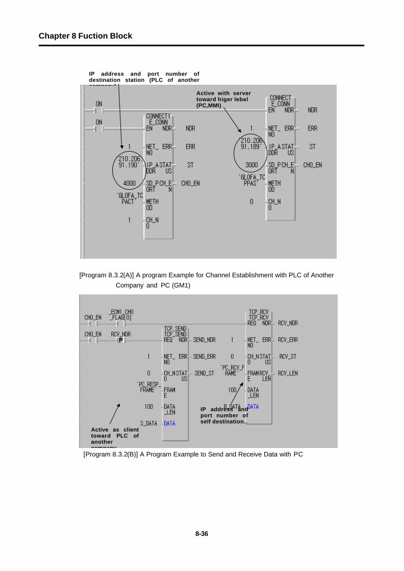
[Program 8.3.2(A)] A program Example for Channel Establishment with PLC of Another
Company and PC (GM1)
[Program 8.3.2(B)] A Program Example to Send and Receive Data with PC
Active with server toward higer lebel (PC,MMI)
IP address and port number of self destination..
Active as client toward PLC of another company
IP address and port number of destination station (PLC of another company)

Chapter 8 Fuction Block
8-37
[Program 8.3.2(C)] A program Example to Send and Receive with PLC of Another Company
In Program 8.3.2(B), if normal data is sent from PC, _ECM1_CH0_FLAG[0] is set. When the data such as PC_RCV_FRAME are received from partner station, 100 data are saved in variable ‘R_DATA’, and it sets ‘RCV_NDR. TCP_SEND Function Block is used as REQ condition using the set‘RCV_NDR’ bit if TCP_RCV Function Block is normally activating. When this bit is set, it sends data of S_DATA as much as 100 in form of ‘PC_RESP_FRAME’ in TCP_SEND Function Block to destination station. (Frame name of ‘PC_RCV_FRAM,‘PC_RESP_FRAME’ is defined in frame editor, and it must be downloaded in Enet module as well.)
When self station is operating with server toward the destination station, you write a program, in which it should send data of self station even after confirming whether the data requested from destination station are normally received.
Program 8.3.2(C)] is operating with the same way as program 8.3.2(B), and if self station is activating as client toward partner station, it first sends data. When the partner station sends data normally, it writes a program in format received.
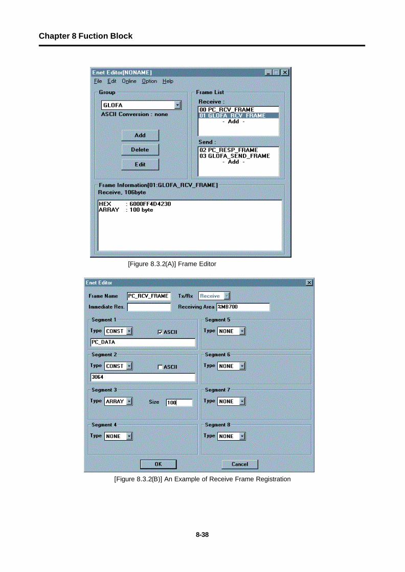
Figure 8.3.2(A)-(C) is showing a setting example of frame editor to perform the above program. Here, an example shows a kind of frame to communicate with PLC of another company.
Chapter 8 Fuction Block
8-38
[Figure 8.3.2(A)] Frame Editor
[Figure 8.3.2(B)] An Example of Receive Frame Registration

Chapter 8 Fuction Block
8-39
[Figure 8.3.2(C)] An Example of Receive Frame Registration

Chapter 8 Fuction Block
8-40
8.4 Function Block Service of Redundancy System
8.4.1 Introduction
1) Introduction
Redundant system of communication using Enet module is Redundancy of Network that sends and receives the same data at the same time configuring two networks like the figure 8.4.1(A).
[Figure 8.4.1(A)] An Example of Redundant System
[Figure 8.4.1(B)] An Example of redundant system
Ethernet Network 1
Ethernet Network 2
G 3 Q - R Y 4 A
RUNCPU I/F RUNFB-SERVECEHS-SERVICEGMWIN-SERVICEGLOFA-SERVICEFTP-SERVICEH/W-ERROR10BASE5 ENABLE10BASE2 ENABLE10BASE-T LINK10BASE-T PLRTYTXRX
L 0001020304050607COM
L 1617181904212223COM
08L 09101112131415COM
08L 25262728293031COM
+- DC24VRELAYAC250V 2ADC24V 2A
PROGRAMMABLECONTROLLER
GLOFA
G M 3 - P A 1 A
PWR
G 3 L - E U E A
RUNCPU I/F RUNFB-SERVECEHS-SERVICEGMWIN-SERVICEGLOFA-SERVICEFTP-SERVICEH/W-ERROR10BASE5 ENABLE10BASE2 ENABLE10BASE-T LINK10BASE-T PLRTYTXRX
MODE
1234
5 06 7 89
0: ON.RUN1: TEST12: TEST2
EXT.POWER
DC IN
+12V
12GFG
10BASE5
10BASE2
10BASE-T
RUN
G M 1 - C P U A
RUNSTOPREMOTEFAIL
ERROR
PAU/REM
STOP
G 3 L - E U E A
RUNCPU I/F RUNFB-SERVECEHS-SERVICEGMWIN-SERVICEGLOFA-SERVICEFTP-SERVICEH/W-ERROR10BASE5 ENABLE10BASE2 ENABLE10BASE-T LINK10BASE-T PLRTYTXRX
MODE
1234
5 06 7 89
0: ON.RUN1: TEST12: TEST2
EXT.POWER
DC IN
+12V
12GFG
10BASE5
10BASE2
10BASE-T
Redundant System of CPU
Single System of CPU
( G M 3 )
PROGRAMMABLECONTROLLER
GLOFA
G M 3 - P A 1 A
PWR
G 3 L - E U E A
RUNCPU I/F RUNFB-SERVECEHS-SERVICEGMWIN-SERVICEGLOFA-SERVICEFTP-SERVICEH/W-ERROR10BASE5 ENABLE10BASE2 ENABLE10BASE-T LINK10BASE-T PLRTYTXRX
MODE
1234
5 06 7 89
0: ON.RUN1: TEST12: TEST2
EXT.POWER
DC IN
+12V
12G
FG
10BASE5
10BASE2
10BASE-T
RUN
G M 1 - C P U A
RUNSTOP
REMOTEFAIL
ERROR
PAU/REMSTOP A
G M 1 - D I F A
A SELA+B
B AELCPU-ACPU-B
A+BB
EXTPWR
RS232C
RUN
G M 1 - C P U A
RUNSTOP
REMOTEFAIL
ERROR
PAU/REMSTOP
G 3 L - E U E A
RUNCPU I/F RUNFB-SERVECEHS-SERVICEGMWIN-SERVICEGLOFA-SERVICEFTP-SERVICEH/W-ERROR10BASE5 ENABLE10BASE2 ENABLE10BASE-T LINK10BASE-T PLRTYTXRX
MODE
1234
5 06 78 90: ON.RUN1: TEST12: TEST2
EXT.POWER
DC IN
+12V
12G
FG
10BASE5
10BASE2
10BASE-T
PROGRAMMABLECONTROLLER
GLOFA
G M 3 - P A 1 A
PWR
Ethernet Network 1
Ethernet Network2
Redundant System of CPU ( G M R )
Single System of CPU ( G M 3 )
G 3 Q - R Y 4 ARUNCPU I/F RUNFB-SERVECEHS-SERVICEGMWIN-SERVICEGLOFA-SERVICEFTP-SERVICEH/W-ERROR10BASE5 ENABLE10BASE2 ENABLE10BASE-T LINK10BASE-T PLRTYTXRX
L 0001020304050607COM
L 1617181904212223COM
08L 09101112131415COM
08L 25262728293031COM
+- DC24VRELAYAC250V 2ADC24V 2A
PROGRAMMABLECONTROLLER
GLOFA
G M 3 - P A 1 A
PWR
G 3 L - E U E ARUNCPU I/F RUNFB-SERVECEHS-SERVICEGMWIN-SERVICEGLOFA-SERVICEFTP-SERVICEH/W-ERROR10BASE5 ENABLE10BASE2 ENABLE10BASE-T LINK10BASE-T PLRTYTXRX
MODE
12345 06 7890: ON.RUN1: TEST12: TEST2
EXT.POWER
DC IN
+12V
12G
FG
10BASE5
10BASE2
10BASE-T
RUN
G M 1 - C P U A
RUNSTOP
REMOTEFAILERROR
PAU/REMSTOP
G 3 Q - R Y 4 ARUNCPU I/F RUNFB-SERVECEHS-SERVICEGMWIN-SERVICEGLOFA-SERVICEFTP-SERVICEH/W-ERROR10BASE5 ENABLE10BASE2 ENABLE10BASE-T LINK10BASE-T PLRTYTXRX
L 0001020304050607COM
L 1617181904212223COM
08L 09101112131415COM
08L 25262728293031COM
+- DC24VRELAYAC250V 2ADC24V 2A
PROGRAMMABLECONTROLLER
GLOFA
G M 3 - P A 1 A
PWR
G 3 L - E U E ARUNCPU I/F RUNFB-SERVECEHS-SERVICEGMWIN-SERVICEGLOFA-SERVICEFTP-SERVICEH/W-ERROR10BASE5 ENABLE10BASE2 ENABLE10BASE-T LINK10BASE-T PLRTYTXRX
MODE
12345 06 7890: ON.RUN1: TEST12: TEST2
EXT.POWER
DC IN
+12V
12G
FG
10BASE5
10BASE2
10BASE-T
RUN
G M 1 - C P U A
RUNSTOP
REMOTEFAILERROR
PAU/REMSTOPPROGRAMMABLE
CONTROLLER
GLOFA
G M 3 - P A 1 A
PWR
G 3 L - E U E ARUNCPU I/F RUNFB-SERVECEHS-SERVICEGMWIN-SERVICEGLOFA-SERVICEFTP-SERVICEH/W-ERROR10BASE5 ENABLE10BASE2 ENABLE10BASE-T LINK10BASE-T PLRTYTXRX
MODE
12345 06 7 890: ON.RUN1: TEST12: TEST2
EXT.POWER
DC IN
+12V
12G
FG
10BASE5
10BASE2
10BASE-T
RUN
G M 1 - C P U A
RUNSTOP
REMOTEFAILERROR
PAU/REMSTOP A
G M 1 - D I F A
A SELA+B
B AELCPU-ACPU-B
A+BB
EXTPWR
RS232C
RUN
G M 1 - C P U A
RUNSTOP
REMOTEFAILERROR
PAU/REMSTOP
G 3 L - E U E A
RUNCPU I/F RUNFB-SERVECEHS-SERVICEGMWIN-SERVICEGLOFA-SERVICEFTP-SERVICEH/W-ERROR10BASE5 ENABLE10BASE2 ENABLE10BASE-T LINK10BASE-T PLRTYTXRX
MODE
12345 06 78 90: ON.RUN1: TEST12: TEST2
EXT.POWER
DC IN
+12V
12G
FG
10BASE5
10BASE2
10BASE-T
PROGRAMMABLECONTROLLER
GLOFA
G M 3 - P A 1 A
PWR

Chapter 8 Fuction Block
8-41
[Figure 8.4.1(C)] An Example of Redundant System
2) Characteristics of redundant Function Block
If Function Block is used in redundant system, it has the following characteristics compared with the existing Function Block.
- In redundant Function Block, 2 services perform their services with other communication path at the same time. Therefore, if one side is not in service, the other side is continuing to do the service.
- Basic I/O data is identical to the existing Function Block. - For action results of dual Function Block, even if only the one of both path succeeds in its
service, it outputs with an answer that it is normal. - Action time of redundant Function Block is a bit loner than the existing Function Block for its
data processing. - The TX/RX size of the dual system is different from that of the single system. (See below)
Total Data Size GMR CPU GM1/2/3/4
READ 1024 Bytes 1400 Bytes
WRITE 400 Bytes 1400 Bytes
HS_LINK 120 Bytes 400 Byyes
- The library used when implementing the redundant system is as follows.
(The name of redundant Function Block is Dxxx. The existing Function Block is xxx.)
210.206.91.190
G 3 L - E U
E A
RUNCPU I/F RUNFB-SERVECEHS-SERVICEGMWIN-SERVICEGLOFA-SERVICEFTP-SERVICEH/W-ERROR
10BASE5 ENABLE10BASE2 ENABLE10BASE-T LINK10BASE-T PLRTYTXRXM O
DE
1234
5 067890 : ON.RUN1: TEST12: TEST2EXT.POWERDC I N
+12V12GFG
10BASE5
10BASE2
10BASE-T
R
UN
G M 1 - C
P U ARUN
STOP
REMOTEFAIL
ERROR
PAU/R
EM ST
O P A
G M 1 - D I
F AA SEL
A+B
B AELCPU-A
CPU-B
A+B
B
EXTPWR
RS232C
R
UN
G M 1 - C
P U ARUN
STOP
REMOTEFAIL
ERROR
PAU/REM ST
O P
PROGRAMMABLE
CONTROLLER
GLO
FA
G M 3 - P A 1 A
PWR
G 3 L - E U
E A
RUN/BPSTX/BPSRS/BPSACK/DATA-B I TNAK/PARITYERR/EVEN-ODDNODEM/STOP-BITSYS-RUN
M ODE
RS-232C
1234
5 0678 9
DISPLAY
RS-422RDARDBSDASDBSG
FG
RUN/BPSTX/BPSRX/BPSACK/DATA-B I TNAK/PARITYERR/EVEN-ODDRS-485/STOP-BITSYS-ERROR
RS-232C
RS-422
G 3 L - E U
E A
RUN/BPSTX/BPSRS/BPSACK/DATA-B I TNAK/PARITYERR/EVEN-ODDNODEM/STOP-BITSYS-RUN
M ODE
RS-232C
12345
06 789
DISPLAY
RS-422RDARDBSDA
SDB
SG
FG
RUN/BPSTX/BPSRX/BPSACK/DATA-B I TNAK/PARITYERR/EVEN-ODDRS-485/STOP-BITSYS-ERROR
RS-232C
RS-422
G 3 L - E U
E A
RUNCPU I/F RUNFB-SERVECEHS-SERVICEGMWIN-SERVICEGLOFA-SERVICEFTP-SERVICEH/W-ERROR
10BASE5 ENABLE10BASE2 ENABLE10BASE-T LINK10BASE-T PLRTYTXRXM O
DE
12345
067890 : ON.RUN1: TE
ST12: TEST2EXT.POWERDC
I N+12V12G
FG
10BASE5
10BASE2
10BASE-T
PROGRAMMABL
E
CONTROLLER
GLO
FA
G M 3 - P A 1 A
PWR
G 3 L - E U
E A
RUN/BPSTX/BPSRS/BPSACK/DATA-B I TNAK/PARITYERR/EVEN-ODDNODEM/STOP-BITSYS-RUN
M ODE
RS-232C
1234
5 0678 9
DISPLAY
RS-422RDARDBSDASDBSG
FG
RUN/BPSTX/BPSRX/BPSACK/DATA-B I TNAK/PARITYERR/EVEN-ODDRS-485/STOP-BITSYS-ERROR
RS-232C
RS-422
G 3 L - E U
E A
RUN/BPSTX/BPSRS/BPSACK/DATA-B I TNAK/PARITYERR/EVEN-ODDNODEM/STOP-BITSYS-RUN
M ODE
RS-232C
12345
06789
DISPLAY
RS-422RDARDBSDASDB
SG
FG
RUN/BPSTX/BPSRX/BPSACK/DATA-B I TNAK/PARITYERR/EVEN-ODDRS-485/STOP-BITSYS-ERROR
RS-232C
RS-422
Desktop System
Hub
G 3 Q - R Y 4 A
RUNCPU I/F RUNFB-SERVECEHS-SERVICEGMWIN-SERVICEGLOFA-SERVICEFTP-SERVICEH/W-ERROR10BASE5 ENABLE10BASE2 ENABLE10BASE-T LINK10BASE-T PLRTYTXRX
L 0001020304050607COM
L 1617181904212223COM
08L 09101112131415COM
08L 25262728293031COM
+- DC24VRELAYAC250V 2ADC24V 2A
PROGRAMMABLECONTROLLER
GLOFA
G M 3 - P A 1 A
PWR
G 3 L - E U E A
RUNCPU I/F RUNFB-SERVECEHS-SERVICEGMWIN-SERVICEGLOFA-SERVICEFTP-SERVICEH/W-ERROR10BASE5 ENABLE10BASE2 ENABLE10BASE-T LINK10BASE-T PLRTYTXRX
MODE
1234
5 06789
0: ON.RUN1: TEST12: TEST2
EXT.POWER
DC IN
+12V
12G
FG
10BASE5
10BASE2
10BASE-T
RUN
G M 1 - C P U A
RUNSTOP
REMOTEFAIL
ERROR
PAU/REM
STOP
G 3 L - F U E A
MODE0: ON.RUN1: TEST12: TEST2
X1
X10
CON1
CON2
1234
5 0678 9
1234
5 0678 9
1234
5 0678 9
RUNLAS
TOKENTX/RXFAULT
Hub
G 3 Q - R Y 4 A
RUNCPU I/F RUNFB-SERVECEHS-SERVICEGMWIN-SERVICEGLOFA-SERVICEFTP-SERVICEH/W-ERROR10BASE5 ENABLE10BASE2 ENABLE10BASE-T LINK10BASE-T PLRTYTXRX
L 0001020304050607COM
L 1617181904212223COM
08L 09101112131415COM
08L 25262728293031COM
+- DC24VRELAYAC250V 2ADC24V 2A
PROGRAMMABLECONTROLLER
GLOFA
G M 3 - P A 1 A
PWR
G 3 L - E U E A
RUNCPU I/F RUNFB-SERVECEHS-SERVICEGMWIN-SERVICEGLOFA-SERVICEFTP-SERVICEH/W-ERROR10BASE5 ENABLE10BASE2 ENABLE10BASE-T LINK10BASE-T PLRTYTXRX
MODE
12345
06789
0: ON.RUN1: TEST12: TEST2
EXT.POWER
DC IN
+12V
12G
FG
10BASE5
10BASE2
10BASE-T
RUN
G M 1 - C P U A
RUNSTOPREMOTEFAIL
ERROR
PAU/REM
STOP
G 3 L - F U E A
MODE0: ON.RUN1: TEST12: TEST2
X1
X10
CON1
CON2
1234
5 0678 9
12345
06789
1234
5 06
78 9
RUNLAS
TOKENTX/RXFAULT
G 3 Q - R Y 4 A
RUNCPU I/F RUNFB-SERVECEHS-SERVICEGMWIN-SERVICEGLOFA-SERVICEFTP-SERVICEH/W-ERROR10BASE5 ENABLE10BASE2 ENABLE10BASE-T LINK10BASE-T PLRTYTXRX
L 0001020304050607COM
L 1617181904212223COM
08L 09101112131415COM
08L 25262728293031COM
+- DC24VRELAYAC250V 2ADC24V 2A
PROGRAMMABLECONTROLLER
GLOFA
G M 3 - P A 1 A
PWR
G 3 L - E U E A
RUNCPU I/F RUNFB-SERVECEHS-SERVICEGMWIN-SERVICEGLOFA-SERVICEFTP-SERVICEH/W-ERROR10BASE5 ENABLE10BASE2 ENABLE10BASE-T LINK10BASE-T PLRTYTXRX
MODE
1234
5 06
78 90: ON.RUN1: TEST12: TEST2
EXT.POWER
DC IN
+12V
12GFG
10BASE5
10BASE2
10BASE-T
RUN
G M 1 - C P U A
RUNSTOP
REMOTEFAILERROR
PAU/REMSTOP
G 3 L - F U E A
MODE0: ON.RUN1: TEST12: TEST2
X1
X10
CON1
CON2
1234
5 06789
1234
5 06
789
1234
5 06789
RUNLAS
TOKENTX/RXFAULT
G 3 Q - R Y 4 A
RUNCPU I/F RUNFB-SERVECEHS-SERVICEGMWIN-SERVICEGLOFA-SERVICEFTP-SERVICEH/W-ERROR10BASE5 ENABLE10BASE2 ENABLE10BASE-T LINK10BASE-T PLRTYTXRX
L 0001020304050607COM
L 1617181904212223COM
08L 09101112131415COM
08L 25262728293031COM
+- DC24VRELAYAC250V 2ADC24V 2A
PROGRAMMABLECONTROLLER
GLOFA
G M 3 - P A 1 A
PWR
G 3 L - E U E A
RUNCPU I/F RUNFB-SERVECEHS-SERVICEGMWIN-SERVICEGLOFA-SERVICEFTP-SERVICEH/W-ERROR10BASE5 ENABLE10BASE2 ENABLE10BASE-T LINK10BASE-T PLRTYTXRX
MODE
1234
5 06789
0: ON.RUN1: TEST12: TEST2
EXT.POWER
DC IN
+12V
12G
FG
10BASE5
10BASE2
10BASE-T
RUN
G M 1 - C P U A
RUNSTOPREMOTEFAIL
ERROR
PAU/REM
STOP
G 3 L - F U E A
MODE0: ON.RUN1: TEST12: TEST2
X1
X10
CON1
CON2
1234
5 06
789
12345
06789
1234
5 06
789
RUN
LASTOKENTX/RXFAULT
상위IP1:210.206.91.189IP2:210.206.90.189
이중화 A SIDEIP:210.206.91.188
이중화 B SIDEIP:210.206.90.188
210.206.91.191 210.206.90.190
IBM Compatible
high order
duplex duplex

Chapter 8 Fuction Block
8-42
Classification GMR CPU GM1/2 CPU GM3 CPU GM4 CPU
Single System -- COMMUNI.1FB COMMUNI.3FB COMMUNI.4FB
COMMUNI.RFB COMMUNI.1FB COMMUNI.3FB COMMUNI.4FB Redundant System -- DUAL_FB.1FB DUAL_FB.3FB DUAL_FB.4FB
[Table 8.4.1(A)] Library of Redundant Function Block
DUAL_FB.xFB is user library edited as redundancy using the existing Function Block.
3) The Kind of Redundant Function Block
The redundant Function Block used to edit a program in redundant system is as follows. Its function, type and use are the same as the content written in chapter 8.1.1 ‘Introduction’.
Kind Service
DE_CONN When logical communication channel is established with destination station.
DTCP_SEND Sends data of self station using TCP/IP to destination station..
DTCP_RCV Receives data of destination station using TCP/IP.
DUDP_SEND Sends data of self station using UDP/IP to destination station.
DUDP_RCV Receives data of destination station using UDP/IP.
[Table 8.4.1(B)] The Kind of Redundant Function Block
4) Action of the Rredundant Function Block
GMR CPU A
Enet A Enet A
Dual FB GM1/2/3/4 CPU Dual FB
Enet B Enet B
GMR CPU B
[Figure 8.4.1(D)] Execution Diagram of Redundant Function Block Service
In the figure 8.4.1(D), two Enet modules are executing the same communication at the same time, but, in user program, they implement it only with dual Function Block.
The following describes characteristics on common I/O of each Function Block.

Chapter 8 Fuction Block
8-43
Input
NET_NO: It specifies slot number, in which communication module is installed, to perform this Function Block out of communication modules installed in the elementary base of PLC of self station. For slot position, slot number ‘0’ is next to CPU, and it increases ‘1’ by ‘1’. Setting range is 0 to 7. In case of GM1/2/3/4 in the following figure, slot number of the left module out of two Enet modules is specified. (Two communication modules must be installed
close each other without fail.) 0 1 2 3 0 1 2 3 0 1 2 3 4
IP_ADDR, D_PORT, S_PORT, CH_NO: If you input Function Block for one module of two Enet modules, both modules are applied at the same time.
Output
Output shows the result for the other one out of both modules, in which its service is normally performed ahead. If both is all abnormally acting, it shows its result in ERR, STATUS. Basic operation is identical to the content in chapter 8.1.2 ‘Kind and Use of Fuction Block’.
G3Q-RY4ARUNCPU I/F RUNFB-SERVECEHS-SERVICEGMWIN-SERVICEGLOFA-SERVICEFTP-SERVICEH/W-ERROR10BASE5 ENABLE10BASE2 ENABLE10BASE-T LINK10BASE-T PLRTYTXRX
L 00010203040506
07COM
L 16171819042122
23COM
08L 09101112131415COM
08L 25262728293031COM
+- DC24VRELAYAC250V 2ADC24V 2A
PROGRAMMABLECONTROLLER
GLO
FA
GM3-PA1A
PWR
G3L-EUEARUNCPU I/F RUNFB-SERVECEHS-SERVICEGMWIN-SERVICEGLOFA-SERVICEFTP-SERVICEH/W-ERROR
10BASE5 ENABLE10BASE2 ENABLE10BASE-T LINK10BASE-T PLRTYTXRX
MODE
1234
5 0678 9
0: ON.RUN1: TEST12: TEST2
EXT.POWER
DC IN
+12V
12GFG
10BASE5
10BASE2
10BASE-T
RUN
GM1-CPUA
RUNSTOP
REMOTEFAIL
ERROR
PAU/REM
STOP
G3L-EUEARUN/BPSTX/BPSRS/BPSACK/DATA-BITNAK/PARITYERR/EVEN-ODDNODEM/STOP-BITSYS-RUN
MODE
RS-232C
1234
5 06789
DISPLAY
RS-422
RDA
RDB
SDA
SDB
SG
FG
RUN/BPSTX/BPSRX/BPSACK/DATA-BITNAK/PARITYERR/EVEN-ODDRS-485/STOP-BITSYS-ERROR
RS-232C
RS-422
G3L-EUEARUNCPU I/F RUNFB-SERVECEHS-SERVICEGMWIN-SERVICEGLOFA-SERVICEFTP-SERVICEH/W-ERROR10BASE5 ENABLE10BASE2 ENABLE10BASE-T LINK10BASE-T PLRTYTXRX
MODE
1234
5 06789
0: ON.RUN1: TEST12: TEST2
EXT.POWER
DC IN
+12V
12G
FG
10BASE5
10BASE2
10BASE-T
RUN
GM1-CPUA
RUNSTOP
REMOTEFAIL
ERROR
PAU/REM
STOP A
GM1-DIFA
A SELA+BB AEL
CPU-ACPU-B
A+B
B
EXTPWR
RS232C
RUN
GM1-CPUA
RUNSTOP
REMOTEFAIL
ERROR
PAU/REM
STOPPROGRAMMABLECONTROLLER
GLO
FA
GM3-PA1A
PWR
G3L-EUEARUN/BPSTX/BPSRS/BPSACK/DATA-BITNAK/PARITYERR/EVEN-ODDNODEM/STOP-BITSYS-RUN
MODE
RS-232C
1234
5 067 89
DISPLAY
RS-422
RDA
RDB
SDA
SDB
SG
FG
RUN/BPSTX/BPSRX/BPSACK/DATA-BITNAK/PARITYERR/EVEN-ODDRS-485/STOP-BITSYS-ERROR
RS-232C
RS-422
G3L-EUEARUN/BPSTX/BPSRS/BPSACK/DATA-BITNAK/PARITYERR/EVEN-ODDNODEM/STOP-BITSYS-RUN
MODE
RS-232C
1234
5 06789
DISPLAY
RS-422
RDA
RDB
SDA
SDB
SG
FG
RUN/BPSTX/BPSRX/BPSACK/DATA-BITNAK/PARITYERR/EVEN-ODDRS-485/STOP-BITSYS-ERROR
RS-232C
RS-422
G3L-EUEARUNCPU I/F RUNFB-SERVECEHS-SERVICEGMWIN-SERVICEGLOFA-SERVICEFTP-SERVICEH/W-ERROR10BASE5 ENABLE10BASE2 ENABLE10BASE-T LINK10BASE-T PLRTYTXRX
MODE
12345 0678 9
0: ON.RUN1: TEST12: TEST2
EXT.POWER
DC IN
+12V
12G
FG
10BASE5
10BASE2
10BASE-T
PROGRAMMABLECONTROLLER
GLO
FA
GM3-PA1A
PWR
G3L-EUEARUN/BPSTX/BPSRS/BPSACK/DATA-BITNAK/PARITYERR/EVEN-ODDNODEM/STOP-BITSYS-RUN
MODE
RS-232C
1234
5 06789
DISPLAY
RS-422
RDA
RDB
SDA
SDB
SG
FG
RUN/BPSTX/BPSRX/BPSACK/DATA-BITNAK/PARITYERR/EVEN-ODDRS-485/STOP-BITSYS-ERROR
RS-232C
RS-422
G3L-EUEARUN/BPSTX/BPSRS/BPSACK/DATA-BITNAK/PARITYERR/EVEN-ODDNODEM/STOP-BITSYS-RUN
MODE
RS-232C
12345 0678 9
DISPLAY
RS-422
RDA
RDB
SDA
SDB
SG
FG
RUN/BPSTX/BPSRX/BPSACK/DATA-BITNAK/PARITYERR/EVEN-ODDRS-485/STOP-BITSYS-ERROR
RS-232C
RS-422
Chapter 8 Fuction Block
8-44
8.4.2 Redundant Function Block Program
1) Redundant System 1
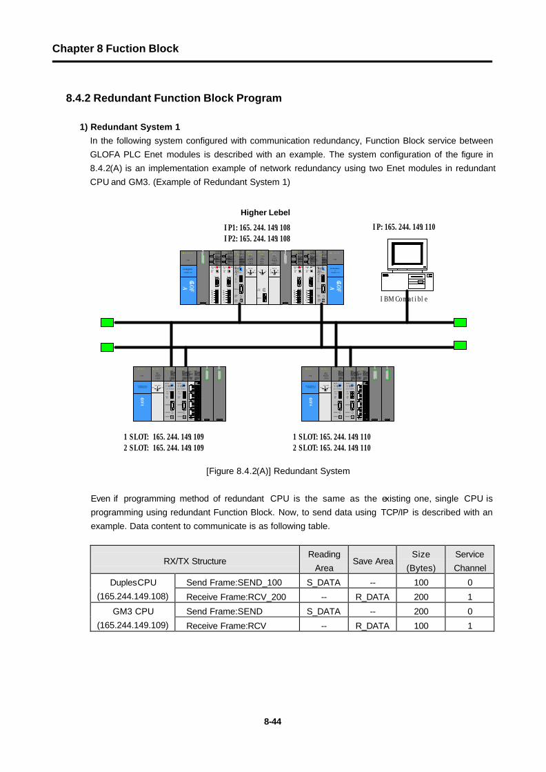
In the following system configured with communication redundancy, Function Block service between GLOFA PLC Enet modules is described with an example. The system configuration of the figure in 8.4.2(A) is an implementation example of network redundancy using two Enet modules in redundant CPU and GM3. (Example of Redundant System 1)
[Figure 8.4.2(A)] Redundant System
Even if programming method of redundant CPU is the same as the existing one, single CPU is programming using redundant Function Block. Now, to send data using TCP/IP is described with an example. Data content to communicate is as following table.
RX/TX Structure Reading
Area Save Area
Size (Bytes)
Service Channel
Send Frame:SEND_100 S_DATA -- 100 0 DuplesCPU (165.244.149.108) Receive Frame:RCV_200 -- R_DATA 200 1
Send Frame:SEND S_DATA -- 200 0 GM3 CPU (165.244.149.109) Receive Frame:RCV -- R_DATA 100 1
1 SLOT: 165.244.149.1092 SLOT: 165.244.149.109
1 SLOT:165.244.149.1102 SLOT:165.244.149.110
G 3 L - E U
E A
RUNCPU I/F RUNFB-SERVECEHS-SERVICEGMWIN-SERVICEGLOFA-SERVICEFTP-SERVICEH/W-ERROR
10BASE5 ENABLE10BASE2 ENABLE10BASE-T LINK10BASE-T PLRTYTXRXM O
DE
12345
06 7890 : ON.RUN1: TE
ST12: TEST2EXT.POWERDC I N
+12V12GFG
10BASE5
10BASE2
10BASE-T
RU
N
G M 1 - C
P U ARUN
STOPREMOTE
FAIL
ERROR
PAU/R
EM ST
O PA
G M 1 - D I
F AA SEL
A+BB AEL
CPU-A
CPU-B
A+BB
EXTPWR
RS232C
R
UN
G M 1 - C
P U ARUN
STOP
REMOTEFAIL
ERROR
PAU/R
EM ST
O P
PROGRAMMABLE
CONTROLLER
GLO
FA
G M 3 - P A 1 A
PWR
G 3 L - E U
E A
RUN/BPSTX/BPSRS/BPSACK/DATA-B I TNAK/PARITYERR/EVEN-ODDNODEM/STOP-BITSYS-RUN
M ODE
RS-232C
1234
5 06789
DISPLAY
RS-422RDARDBSDA
SDB
SG
FG
RUN/BPSTX/BPSRX/BPSACK/DATA-B I TNAK/PARITYERR/EVEN-ODDRS-485/STOP-BITSYS-ERROR
RS-232C
RS-422
G 3 L - E U
E A
RUN/BPSTX/BPSRS/BPSACK/DATA-B I TNAK/PARITYERR/EVEN-ODDNODEM/STOP-BITSYS-RUN
M ODE
RS-232C
12345
06789
DISPLAY
RS-422RDARDBSDASDB
SG
FG
RUN/BPSTX/BPSRX/BPSACK/DATA-B I TNAK/PARITYERR/EVEN-ODDRS-485/STOP-BITSYS-ERROR
RS-232C
RS-422
G 3 L - E U
E A
RUNCPU I/F RUNFB-SERVECEHS-SERVICEGMWIN-SERVICEGLOFA-SERVICEFTP-SERVICEH/W-ERROR
10BASE5 ENABLE10BASE2 ENABLE10BASE-T LINK10BASE-T PLRTYTXRXM O
DE
12345
067890 : ON.RUN1: TE
ST12: TEST2EXT.POWERDC I N+1
2V12GFG
10BASE5
10BASE2
10BASE-T
PROGRAMMABL
E
CONTROLLER
GLO
FA
G M 3 - P A 1 A
PWR
G 3 L - E U
E A
RUN/BPSTX/BPSRS/BPSACK/DATA-B I TNAK/PARITYERR/EVEN-ODDNODEM/STOP-BITSYS-RUN
M ODE
RS-232C
12345
06789
DISPLAY
RS-422RDARDBSDA
SDB
SG
FG
RUN/BPSTX/BPSRX/BPSACK/DATA-B I TNAK/PARITYERR/EVEN-ODDRS-485/STOP-BITSYS-ERROR
RS-232C
RS-422
G 3 L - E U
E A
RUN/BPSTX/BPSRS/BPSACK/DATA-B I TNAK/PARITYERR/EVEN-ODDNODEM/STOP-BITSYS-RUN
M ODE
RS-232C
1234
5 06789
DISPLAY
RS-422RDARDBSDASDB
SG
FG
RUN/BPSTX/BPSRX/BPSACK/DATA-B I TNAK/PARITYERR/EVEN-ODDRS-485/STOP-BITSYS-ERROR
RS-232C
RS-422
G 3 Q - R Y 4 A
RUNCPU I/F RUNFB-SERVECEHS-SERVICEGMWIN-SERVICEGLOFA-SERVICEFTP-SERVICEH/W-ERROR10BASE5 ENABLE10BASE2 ENABLE10BASE-T LINK10BASE-T PLRTYTXRX
L 00010203040506
07COM
L 16171819042122
23COM
08L 09101112131415COM
08L 25262728293031COM
+- DC24VRELAYAC250V 2ADC24V 2A
PROGRAMMABLECONTROLLER
GLOFA
G M 3 - P A 1 A
PWR
RUN
G M 1 - C P U A
RUNSTOP
REMOTEFAIL
ERROR
PAU/REM
STOP
G 3 L - E U E A
RUNCPU I/F RUNFB-SERVECEHS-SERVICEGMWIN-SERVICEGLOFA-SERVICEFTP-SERVICEH/W-ERROR10BASE5 ENABLE10BASE2 ENABLE10BASE-T LINK10BASE-T PLRTYTXRX
MODE
1234
5 06
78 90: ON.RUN1: TEST12: TEST2
EXT.POWER
DC IN
+12V
12GFG
10BASE5
10BASE2
10BASE-T
G 3 L - E U E A
RUNCPU I/F RUNFB-SERVECEHS-SERVICEGMWIN-SERVICEGLOFA-SERVICEFTP-SERVICEH/W-ERROR10BASE5 ENABLE10BASE2 ENABLE10BASE-T LINK10BASE-T PLRTYTXRX
MODE
1234
5 06
7890: ON.RUN1: TEST12: TEST2
EXT.POWER
DC IN
+12V
12GFG
10BASE5
10BASE2
10BASE-T
상위IP1:165.244.149.108IP2:165.244.149.108
G 3 Q - R Y 4 A
RUNCPU I/F RUNFB-SERVECEHS-SERVICEGMWIN-SERVICEGLOFA-SERVICEFTP-SERVICEH/W-ERROR10BASE5 ENABLE10BASE2 ENABLE10BASE-T LINK10BASE-T PLRTYTXRX
L 00010203040506
07COM
L 16171819042122
23COM
08L 09101112131415COM
08L 25262728293031COM
+- DC24VRELAYAC250V 2ADC24V 2A
PROGRAMMABLECONTROLLER
GLOFA
G M 3 - P A 1 A
PWR
RUN
G M 1 - C P U A
RUNSTOP
REMOTEFAIL
ERROR
PAU/REM
STOP
G 3 L - E U E A
RUNCPU I/F RUNFB-SERVECEHS-SERVICEGMWIN-SERVICEGLOFA-SERVICEFTP-SERVICEH/W-ERROR10BASE5 ENABLE10BASE2 ENABLE10BASE-T LINK10BASE-T PLRTYTXRX
MODE
1234
5 06
78 90: ON.RUN1: TEST12: TEST2
EXT.POWER
DC IN
+12V
12GFG
10BASE5
10BASE2
10BASE-T
G 3 L - E U E A
RUNCPU I/F RUNFB-SERVECEHS-SERVICEGMWIN-SERVICEGLOFA-SERVICEFTP-SERVICEH/W-ERROR10BASE5 ENABLE10BASE2 ENABLE10BASE-T LINK10BASE-T PLRTYTXRX
MODE
1234
5 06
7890: ON.RUN1: TEST12: TEST2
EXT.POWER
DC IN
+12V
12GFG
10BASE5
10BASE2
10BASE-T
IBM Compatible
IP:165.244.149.110
Higher Lebel
Chapter 8 Fuction Block
8-45
Path Connection Method Send Frame Receive Frame
Redundancy -> GM3
TCP_ACTIVE(based on redundancy) SEND_100 -
Redundancy <- GM3
TCP_PTOSIVE(based on redundancy) - RCV_200
GM3 -> Rredundancy
TCP_ACTIVE (based on GM3 ) SEND -
GM3 -> Redundancy
TCP_PTOSIVE(based on GM3) - RCV
[Table 8.4.2(A)] Data Definition to Communicate
A) Program Editing on redundant CPU(GMR-CPUA) Side
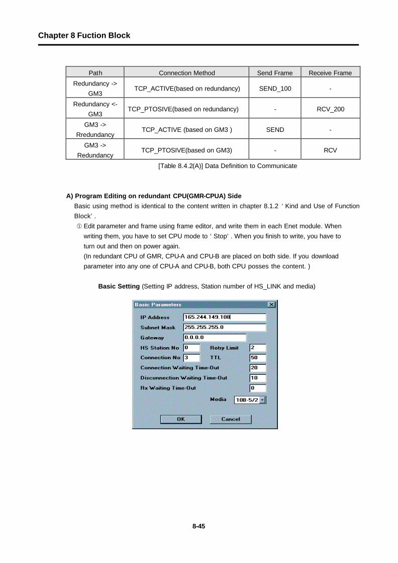
Basic using method is identical to the content written in chapter 8.1.2 ‘Kind and Use of Function Block’. ¬ Edit parameter and frame using frame editor, and write them in each Enet module. When
writing them, you have to set CPU mode to ‘Stop’. When you finish to write, you have to turn out and then on power again. (In redundant CPU of GMR, CPU-A and CPU-B are placed on both side. If you download parameter into any one of CPU-A and CPU-B, both CPU posses the content. )
Basic Setting (Setting IP address, Station number of HS_LINK and media)

Chapter 8 Fuction Block
8-46
Editing of RX Frame
Editing of RX Frame

Chapter 8 Fuction Block
8-47
Write user program.
(Please use it after you insert library ‘COMMUNI.RFB’)
Saving area of data to be sent. (type, and size of the byte array :100)
Sending with the channel number ‘0’.
Channel establishment with client
IP address and port of destination station.
It gets ‘1’ if connection is done.
Keeps ‘1’ when connecting
Saving area of data to be received. (type, and size of the byte array :200)
Receiving with the channel number ‘1’
Channel establishment with server
IP addrss and port of self station. _ECM3_CH0_FLAG[0]

Chapter 8 Fuction Block
8-48
® Write with PLC after Compile/Make. In confirmation of activation for sending, as redundant CPU (self station) acts with TCP ACTIVE toward the destination station (GM3), you should activate the connection of self station (CON_S=1) after being established toward the self station. In confirmation of activation for receiving, on the contrary, you should activate the self station’s connection (CON_R=1), and then activate the connection of the destination station. In other words, when you do the connection, you should first operate PASSIVE (or SELECT), then ACTIVE.
B) Program editing of single CPU(GM3-CPUA) side
The single CPU is using redundant Function Block in programming unlikely to the existing programming method ¬ You write them in each Enet module after you edit parameter and frame using the frame
editor. When writing, you should stop the CPU mode, and after writing all, you should turn off the power, and then turn it on again. (You should write the program for the first Enet module of two Enet modules. The communication of TX/RX through the second modeul is automatically managed within the Function Block. Two Enet modules must be equipped in Base one after the other.
Basic Setting (Setting of IP address and HS_LINK station number and media.,)

Chapter 8 Fuction Block
8-49
Editing of TX Frame
Editing of RX Frame

Chapter 8 Fuction Block
8-50
Edit user program.
(Please use it after inserting library ‘DUAL_FB.3FB’.)
The redundant Function Block outputs ‘Channel Enable’ in two places. That is the difference from the connection Funnction Block used in the single module. It is the result operated in two Enet mocules, and when one of them or both become ‘Enable’, you use it as REQ condition of RX/TX Function Block.
® In confirmation of activation for sending, as Gm3 (self station) acts with TCP ACTIVE toward the destination station (redundant CPU), you should activate the connection of self station (CON_S=1) after being established toward the self station. In confirmation of activation for receiving, on the contrary, you should activate the self station’s connection (CON_R=1), and then activate the connection of the destination station. In other words, when you do the connection, you should first operate PASSIVE (or SELECT), then ACTIVE.
Saving area of data to be sent. (type, and size of the byte array :100)
Channel establishment with client
IP address and port of destination station.
Saving area of data to be received. (type, and size of the byte array :200)
IP addrss and port of self station

Chapter 8 Fuction Block
8-51
2) Redundant System 2
In the following system configured with communication redundancy, Function Block service between GLOFA PLC Enet modules is described with an example. The system configuration of the figure in 8.4.2(B) is an implementation example of network redundancy using two Enet modules in redundant CPU and GM3. (Example of Redundant System 1)
[Figure 8.4.2(B)] An Example of the Redundant System
Even if programming method of redundant CPU is the same as the existing one, single CPU is programming using redundant Function Block. Now, to send data using TCP/IP is described with an example. Data content to communicate is as following table.
RX/TX Structure Reading
Area Save Area
Size (Bytes)
Service Channel
Send Frame:SEND_100 S_DATA - 100 0 Redundant CPU (210.206.90.188) (210.206.90.189)
Receive Frame:RCV_200 - R_DATA 200 0
Send Frame:SEND S_DATA - 200 0 GM1 CPU (210.206.90.189) Receive Frame RCV R_DATA 100 0
Send Frame SEND S_DATA - 200 0 GM3 CPU (210.206.91.189) Receive Frame RCV - R_DATA 100 0
Path Connection Method Send Frame Receive Frame
Redundancy -> GM-0 TCP_ACTIVE(based on redundancy) SEND_100 RCV 200-
Redundancy <- GM1-1 TCP_ACTIVE(based on redundancy) SEND_100- RCV_200
GM-0 -> Redundancy TCP_PASSIVE (based on GM1 ) SEND RCV-
GM-1 -> Redundancy TCP_PASSIVE(based on GM1) SEND RCV
[Table 8.4.2(B)] Data Definition to Communicate
Dedicated Ethernet Network 1
Redundant CPU System(GMR) Single CPU System(GM1)
G 3 Q - R Y 4 ARUNCPU I/F RUNFB-SERVECEHS-SERVICEGMWIN-SERVICEGLOFA-SERVICEFTP-SERVICEH/W-ERROR10BASE5 ENABLE10BASE2 ENABLE10BASE-T LINK10BASE-T PLRTYTXRX
L 0001020304050607COM
L 1617181904212223COM
08L 09101112131415COM
08L 25262728293031COM
+- DC24VRELAYAC250V 2ADC24V 2A
PROGRAMMABLECONTROLLER
GLOFA
G M 3 - P A 1 A
PWR
G 3 L - E U E ARUNCPU I/F RUNFB-SERVECEHS-SERVICEGMWIN-SERVICEGLOFA-SERVICEFTP-SERVICEH/W-ERROR10BASE5 ENABLE10BASE2 ENABLE10BASE-T LINK10BASE-T PLRTYTXRX
MODE
1234
5 06
7890: ON.RUN1: TEST12: TEST2
EXT.POWER
DC IN
+12V
12G
FG
10BASE5
10BASE2
10BASE-T
RUN
G M 1 - C P U A
RUNSTOP
REMOTEFAILERROR
PAU/REMSTOP
G 3 Q - R Y 4 ARUNCPU I/F RUNFB-SERVECEHS-SERVICEGMWIN-SERVICEGLOFA-SERVICEFTP-SERVICEH/W-ERROR10BASE5 ENABLE10BASE2 ENABLE10BASE-T LINK10BASE-T PLRTYTXRX
L 0001020304050607COM
L 1617181904212223COM
08L 09101112131415COM
08L 25262728293031COM
+- DC24VRELAYAC250V 2ADC24V 2A
PROGRAMMABLECONTROLLER
GLOFA
G M 3 - P A 1 A
PWR
G 3 L - E U E ARUNCPU I/F RUNFB-SERVECEHS-SERVICEGMWIN-SERVICEGLOFA-SERVICEFTP-SERVICEH/W-ERROR10BASE5 ENABLE10BASE2 ENABLE10BASE-T LINK10BASE-T PLRTYTXRX
MODE
1234
5 06
7890: ON.RUN1: TEST12: TEST2
EXT.POWER
DC IN
+12V
12G
FG
10BASE5
10BASE2
10BASE-T
RUN
G M 1 - C P U A
RUNSTOP
REMOTEFAILERROR
PAU/REMSTOPPROGRAMMABLE
CONTROLLER
GLOFA
G M 3 - P A 1 A
PWR
G 3 L - E U E ARUNCPU I/F RUNFB-SERVECEHS-SERVICEGMWIN-SERVICEGLOFA-SERVICEFTP-SERVICEH/W-ERROR10BASE5 ENABLE10BASE2 ENABLE10BASE-T LINK10BASE-T PLRTYTXRX
MODE
1234
5 06 7 89
0: ON.RUN1: TEST12: TEST2
EXT.POWER
DC IN
+12V
12GFG
10BASE5
10BASE2
10BASE-T
RUN
G M 1 - C P U A
RUNSTOPREMOTEFAIL
ERROR
PAU/REMSTOP A
G M 1 - D I F A
A SELA+BB AEL
CPU-ACPU-B
A+BB
EXTPWR
RS232C
RUN
G M 1 - C P U A
RUNSTOPREMOTEFAIL
ERROR
PAU/REMSTOP
G 3 L - E U E ARUNCPU I/F RUNFB-SERVECEHS-SERVICEGMWIN-SERVICEGLOFA-SERVICEFTP-SERVICEH/W-ERROR10BASE5 ENABLE10BASE2 ENABLE10BASE-T LINK10BASE-T PLRTYTXRX
MODE
1234
5 06 78 90: ON.RUN1: TEST12: TEST2
EXT.POWER
DC IN
+12V
12GFG
10BASE5
10BASE2
10BASE-T
PROGRAMMABLECONTROLLER
GLOFA
G M 3 - P A 1 A
PWR
210.206.90.188
Dedicated Ethernet Network 2
210.206.91.188 210.206.90.189 210.206.91.189

Chapter 8 Fuction Block
8-52
A) Program Editing on Redundant CPU(GMR-CPUA) Side
Basic using method is identical to the content written in chapter 8.1.2 ‘Kind and Use of Function Block’.
¬ Edit parameter and frame using frame editor, and write them in each Enet module. When writing them, you have to set CPU mode to ‘Stop’. When you finish to write, you have to turn out and then on power again. (Gateway must be set up when using public network) (In redundant CPU of GMR, CPU-A and CPU-B are placed on both side. If you download parameter into any one of CPU-A and CPU-B, both CPU posses the content. )
Basic Setting (Setting IP address, Station number of HS_LINK and media)
Editing of TX Frame

Chapter 8 Fuction Block
8-53
Editing of RX Frame
Write user program. (Please use it after you insert library ‘COMMUNI.RFB’)

Chapter 8 Fuction Block
8-54
® Write with PLC after Compile/Make. In confirmation of activation for sending, as redundant CPU (self station) acts with TCP
ACTIVE toward the destination station (GM3), you should activate the connection of self station (CON_S=1) after being established toward the self station.
In confirmation of activation for receiving, on the contrary, you should activate the self station’s connection (CON_R=1), and then activate the connection of the destination station. In other words, when you do the connection, you should first operate PASSIVE (or SELECT), then ACTIVE.
B) Program editing of single CPU(GM3-CPUA) side
The single CPU is using redundant Function Block in programming unlikely to the existing programming method. ¬ You write them in each Enet module after you edit parameter and frame using the frame editor.
When writing, you should stop the CPU mode, and after writing all, you should turn off the power, and then turn it on again. (You should write the program for the first Enet module of two Enet modules. The communication of TX/RX through the second modeul is automatically managed within the Function Block. Two Enet modules must be equipped in Base one after the other.
Basic Setting

Chapter 8 Fuction Block
8-55
Editing of TX Frame
Editing of RX Frame

Chapter 8 Fuction Block
8-56
Write user program.
(Please use it after you insert library ‘DUAL_FB.3FB’)
The redundant Function Block outputs ‘Channel Enable’ in two places. That is the difference from the connection Funnction Block used in the single module. It is the result operated in two Enet mocules, and when one of them or both become ‘Enable’, you use it as REQ condition of RX/TX Function Block.
® In confirmation of activation for sending, as Gm3 (self station) acts with TCP ACTIVE toward the destination station (redundant CPU, you should activate the connection of self station (CON_S=1) after being established toward the self station. In confirmation of activation for receiving, on the contrary, you should activate the self station’s connection (CON_R=1), and then activate the connection of the destination station. In other words, when you do the connection, you should first operate PASSIVE (or SELECT), then ACTIVE.