chapter 7 requirements modeling: flow, behavior, …blk/cs5666/requirements/ch07...these slides are...
TRANSCRIPT
These slides are designed to accompany Software Engineering: A Practitioner’s Approach, 7/e (McGraw-Hill 2009). Slides copyright 2009 by Roger Pressman.
Chapter 7 Requirements Modeling: Flow, Behavior, Patterns, and WebApps
Slides in this presentation were taken from two sources:
Software Engineering: A Practitioner’s Approach, 7/eby Roger S. Pressman
Slides copyright © 1996, 2001, 2005, 2009 by Roger S. Pressman
Object-Oriented Software Engineering: Using UML, Patterns, and Java, 2/e, Chapter 5by Bernd Bruegge and Allen H. Dutoit
The footer information identifies the source for each slide.
These slides are designed to accompany Software Engineering: A Practitioner’s Approach, 7/e (McGraw-Hill 2009). Slides copyright 2009 by Roger Pressman.
Requirements Modeling StrategiesOne view of requirements modeling, called structured analysis, considers data and the processes that transform the data as separate entities.
Data objects are modeled in a way that defines their attributes and relationships. Processes that manipulate data objects are modeled in a manner that shows how they transform data as data objects flow through the system.
A second approach to analysis modeled, called object-oriented analysis, focuses on
the definition of classes andthe manner in which they collaborate with one another to effect customer requirements.
These slides are designed to accompany Software Engineering: A Practitioner’s Approach, 7/e (McGraw-Hill 2009). Slides copyright 2009 by Roger Pressman.
Flow-Oriented Modeling
Represents how data objects are transformed at they move through the systemdata flow diagram (DFD) is the diagrammatic form that is usedConsidered by many to be an “old school” approach, but continues to provide a view of the system that is unique—it should be used to supplement other analysis model elements

These slides are designed to accompany Software Engineering: A Practitioner’s Approach, 7/e (McGraw-Hill 2009). Slides copyright 2009 by Roger Pressman.
The Flow Model
Every computer-based system is an information transform ....
computerbased
systeminput output
These slides are designed to accompany Software Engineering: A Practitioner’s Approach, 7/e (McGraw-Hill 2009). Slides copyright 2009 by Roger Pressman.
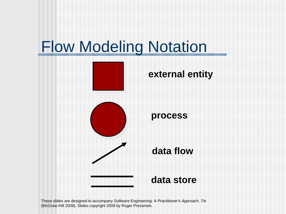
Flow Modeling Notationexternal entity
process
data flow
data store

These slides are designed to accompany Software Engineering: A Practitioner’s Approach, 7/e (McGraw-Hill 2009). Slides copyright 2009 by Roger Pressman.
External Entity
A producer or consumer of data
Examples: a person, a device, a sensor
Another example: computer-basedsystem
Data must always originate somewhereand must always be sent to something
These slides are designed to accompany Software Engineering: A Practitioner’s Approach, 7/e (McGraw-Hill 2009). Slides copyright 2009 by Roger Pressman.
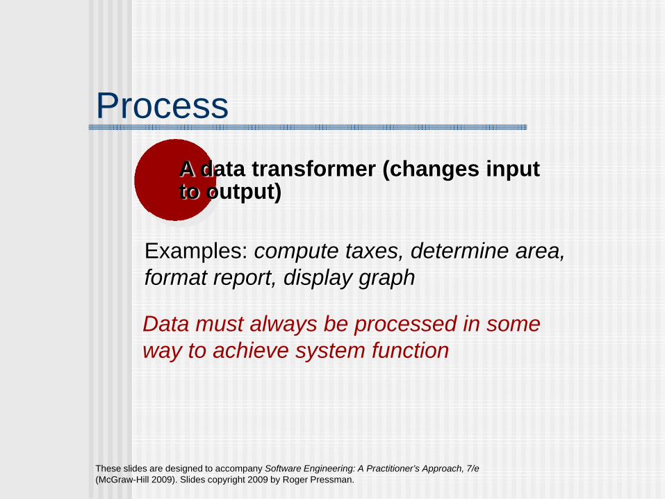
ProcessA data transformer (changes inputto output)
Examples: compute taxes, determine area,format report, display graph
Data must always be processed in some way to achieve system function
These slides are designed to accompany Software Engineering: A Practitioner’s Approach, 7/e (McGraw-Hill 2009). Slides copyright 2009 by Roger Pressman.
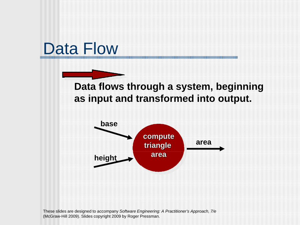
Data Flow
Data flows through a system, beginningas input and transformed into output.
computetriangle
area
base
height
area
These slides are designed to accompany Software Engineering: A Practitioner’s Approach, 7/e (McGraw-Hill 2009). Slides copyright 2009 by Roger Pressman.
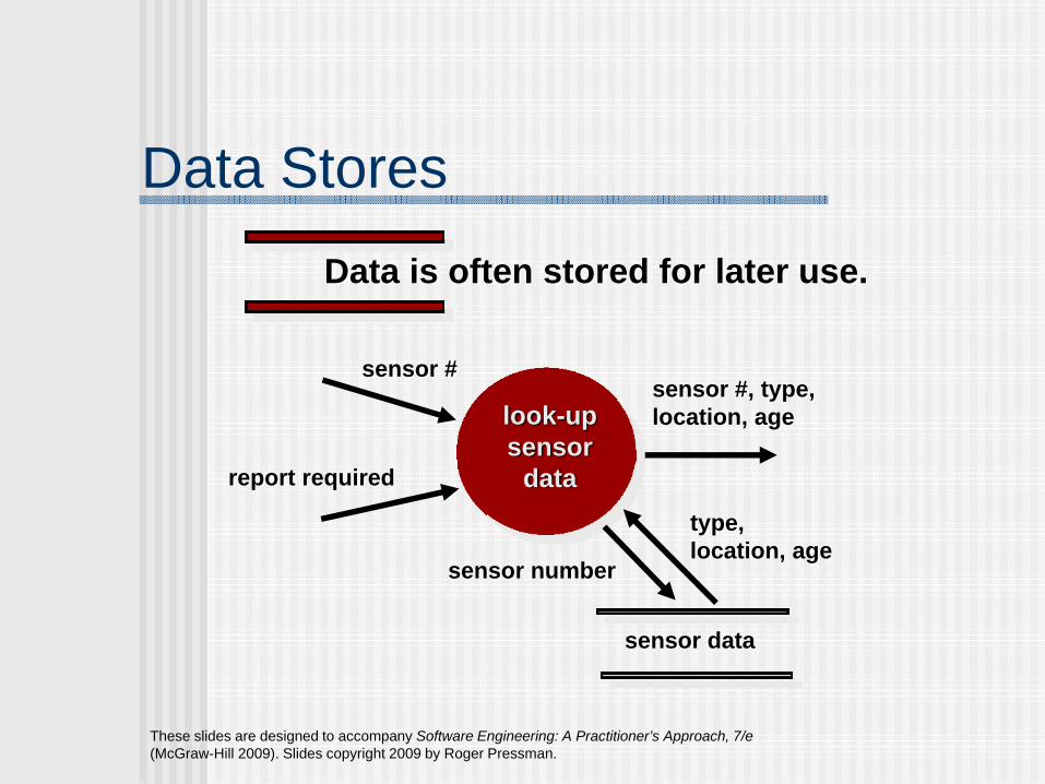
Data StoresData is often stored for later use.
look-upsensor
data
sensor #
report required
sensor #, type, location, age
sensor data
sensor number
type, location, age
These slides are designed to accompany Software Engineering: A Practitioner’s Approach, 7/e (McGraw-Hill 2009). Slides copyright 2009 by Roger Pressman.
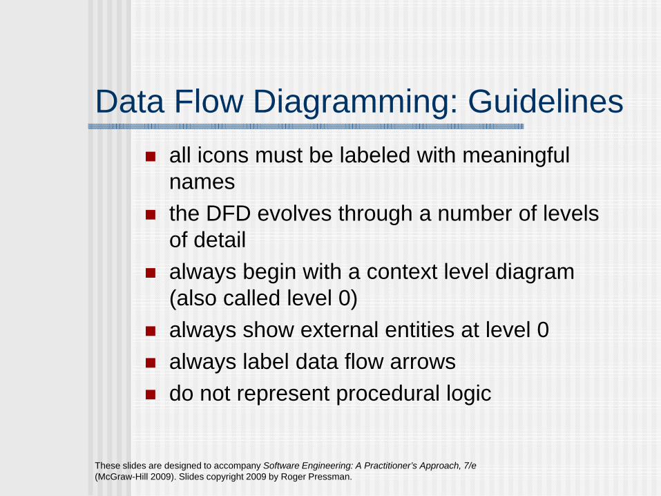
Data Flow Diagramming: Guidelinesall icons must be labeled with meaningful namesthe DFD evolves through a number of levels of detailalways begin with a context level diagram (also called level 0)always show external entities at level 0always label data flow arrowsdo not represent procedural logic

These slides are designed to accompany Software Engineering: A Practitioner’s Approach, 7/e (McGraw-Hill 2009). Slides copyright 2009 by Roger Pressman.
Constructing a DFD—Ireview user scenarios and/or the data model to isolate data objects and use a grammatical parse to determine “operations”determine external entities (producers and consumers of data)create a level 0 DFD
These slides are designed to accompany Software Engineering: A Practitioner’s Approach, 7/e (McGraw-Hill 2009). Slides copyright 2009 by Roger Pressman.
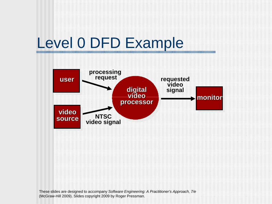
Level 0 DFD Example
userprocessing
request
videosource NTSC
video signal
digitalvideo
processor
requestedvideosignal
monitor
These slides are designed to accompany Software Engineering: A Practitioner’s Approach, 7/e (McGraw-Hill 2009). Slides copyright 2009 by Roger Pressman.
Constructing a DFD—IIwrite a narrative describing the transformparse to determine next level transforms“balance” the flow to maintain data flow continuitydevelop a level 1 DFDuse a 1:5 (approx.) expansion ratio

These slides are designed to accompany Software Engineering: A Practitioner’s Approach, 7/e (McGraw-Hill 2009). Slides copyright 2009 by Roger Pressman.
The Data Flow Hierarchy
Pa bx y
p1p2
p3p4 5
a
b
c
de
f
g
level 0
level 1

These slides are designed to accompany Software Engineering: A Practitioner’s Approach, 7/e (McGraw-Hill 2009). Slides copyright 2009 by Roger Pressman.
Flow Modeling Noteseach bubble is refined until it does just one thingthe expansion ratio decreases as the number of levels increasemost systems require between 3 and 7 levels for an adequate flow modela single data flow item (arrow) may be expanded as levels increase (data dictionary provides information)

These slides are designed to accompany Software Engineering: A Practitioner’s Approach, 7/e (McGraw-Hill 2009). Slides copyright 2009 by Roger Pressman.
Process Specification (PSPEC)
PSPECnarrativepseudocode (PDL)equationstablesdiagrams and/or charts
bubble

These slides are designed to accompany Software Engineering: A Practitioner’s Approach, 7/e (McGraw-Hill 2009). Slides copyright 2009 by Roger Pressman.
Maps into
DFDs: A Look Ahead
analysis model
design model
These slides are designed to accompany Software Engineering: A Practitioner’s Approach, 7/e (McGraw-Hill 2009). Slides copyright 2009 by Roger Pressman.
Control Flow ModelingRepresents “events” and the processes that manage eventsAn “event” is a Boolean condition that can be ascertained by:
• listing all sensors that are "read" by the software.• listing all interrupt conditions.• listing all "switches" that are actuated by an operator.• listing all data conditions.• recalling the noun/verb parse that was applied to the
processing narrative, review all "control items" as possible CSPEC inputs/outputs.

These slides are designed to accompany Software Engineering: A Practitioner’s Approach, 7/e (McGraw-Hill 2009). Slides copyright 2009 by Roger Pressman.
Control Specification (CSPEC)The CSPEC can be:
state diagram (sequential spec)
state transition table
decision tables
activation tables
combinatorial spec

These slides are designed to accompany Software Engineering: A Practitioner’s Approach, 7/e (McGraw-Hill 2009). Slides copyright 2009 by Roger Pressman.
Behavioral ModelingThe behavioral model indicates how software will respond to external events or stimuli. To create the model, the analyst must perform the following steps:
• Evaluate all use-cases to fully understand the sequence of interaction within the system.
• Identify events that drive the interaction sequence and understand how these events relate to specific objects.
• Create a sequence for each use-case.• Build a state diagram for the system.• Review the behavioral model to verify accuracy and
consistency.

These slides are designed to accompany Software Engineering: A Practitioner’s Approach, 7/e (McGraw-Hill 2009). Slides copyright 2009 by Roger Pressman.
State RepresentationsIn the context of behavioral modeling, two different characterizations of states must be considered:
the state of each class as the system performs its function andthe state of the system as observed from the outside as the system performs its function
The state of a class takes on both passive and active characteristics [CHA93].
A passive state is simply the current status of all of an object’s attributes.The active state of an object indicates the current status of the object as it undergoes a continuing transformation or processing.

These slides are designed to accompany Software Engineering: A Practitioner’s Approach, 7/e (McGraw-Hill 2009). Slides copyright 2009 by Roger Pressman.
State Diagram for the ControlPanel Class

These slides are designed to accompany Software Engineering: A Practitioner’s Approach, 7/e (McGraw-Hill 2009). Slides copyright 2009 by Roger Pressman.
The States of a Systemstate—a set of observable circum-stances that characterizes the behavior of a system at a given timestate transition—the movement from one state to anotherevent—an occurrence that causes the system to exhibit some predictable form of behavioraction—process that occurs as a consequence of making a transition

Bernd Bruegge & Allen H. Dutoit Object-Oriented Software Engineering: Using UML, Patterns, and Java 17
UML Statechart Diagram Notation
State2State1 Event1(attr) [condition]/action
entry /actionexit/action
♦ Notation based on work by HarelAdded are a few object-oriented modifications
♦ A UML statechart diagram can be mapped into a finite state machine
do/Activity
Also: internal transition and deferred events
Event triggerWith parameters
Guardcondition
Bernd Bruegge & Allen H. Dutoit Object-Oriented Software Engineering: Using UML, Patterns, and Java 18
Statechart Diagrams
♦ Graph whose nodes are states and whose directed arcs are transitions labeled by event names.
♦ We distinguish between two types of operations in statecharts:
Activity: Operation that takes time to completeassociated with states
Action: Instantaneous operation associated with eventsassociated with states (reduces drawing complexity): Entry, Exit, Internal Action
♦ A statechart diagram relates events and states for one class
An object model with a set of objects has a set of state diagrams

Bernd Bruegge & Allen H. Dutoit Object-Oriented Software Engineering: Using UML, Patterns, and Java 19
State♦ An abstraction of the attributes of a class
State is the aggregation of several attributes a class♦ Basically an equivalence class of all those attribute values
and links that do no need to be distinguished as far as the control structure of the system is concerned
Example: State of a bankA bank is either solvent or insolvent
♦ State has duration

Bernd Bruegge & Allen H. Dutoit Object-Oriented Software Engineering: Using UML, Patterns, and Java 20
Example of a StateChart Diagram
do: test item and compute change
do: make changedo: dispense item
Idle
[item empty] [select(item)]
[change=0] [change>0]
[change<0]
Collect Moneycoins_in(amount) / add to balance
coins_in(amount) / set balance
cancel / refund coins
Bernd Bruegge & Allen H. Dutoit Object-Oriented Software Engineering: Using UML, Patterns, and Java 21
Nested State Diagram
♦ Activities in states are composite items denoting other lower-level state diagrams
♦ A lower-level state diagram corresponds to a sequence of lower-level states and events that are invisible in the higher-level diagram.
♦ Sets of substates in a nested state diagram denote a superstate are enclosed by a large rounded box, also called contour.
Bernd Bruegge & Allen H. Dutoit Object-Oriented Software Engineering: Using UML, Patterns, and Java 22
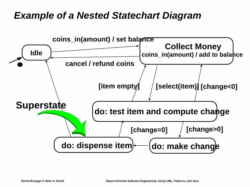
Example of a Nested Statechart Diagram
do: dispense item
[change=0]
Superstate
IdleCollect Money
coins_in(amount) / add to balance
do: test item and compute change
do: make change
[change>0]
[item empty] [select(item)] [change<0]
coins_in(amount) / set balance
cancel / refund coins

Bernd Bruegge & Allen H. Dutoit Object-Oriented Software Engineering: Using UML, Patterns, and Java 23
Expanding activity “do:dispense item”
do: move arm to row
armready
‘Dispense item’ asan atomic activity:
‘Dispense item’ as a composite activity:
do: dispense item
[change=0]
armready
do: move arm to column
do: push itemoff shelf

Bernd Bruegge & Allen H. Dutoit Object-Oriented Software Engineering: Using UML, Patterns, and Java 24
Superstates
♦ Goal:Avoid spaghetti models Reduce the number of lines in a state diagram
♦ Transitions from other states to the superstate enter the first substate of the superstate.
♦ Transitions to other states from a superstate are inherited by all the substates (state inheritance)
Bernd Bruegge & Allen H. Dutoit Object-Oriented Software Engineering: Using UML, Patterns, and Java 25
Modeling Concurrency
Two types of concurrency1. System concurrency
State of overall system as the aggregation of state diagrams, one for each object. Each state diagram is executing concurrently with the others.
2. Object concurrencyAn object can be partitioned into subsets of states (attributes and links) such that each of them has its own subdiagram. The state of the object consists of a set of states: one state from each subdiagram.State diagrams are divided into subdiagrams by dotted lines.

Bernd Bruegge & Allen H. Dutoit Object-Oriented Software Engineering: Using UML, Patterns, and Java 26
Example of Concurrency within an Object
Emitting
Setting ReadyUp to reset
Do: DispenseCash
Do: EjectCard
Ready
Cash taken
Card taken
SynchronizationSplitting control
Bernd Bruegge & Allen H. Dutoit Object-Oriented Software Engineering: Using UML, Patterns, and Java 27
State Chart Diagram vs Sequence Diagram
♦ State chart diagrams help to identify:Changes to an individual object over time
♦ Sequence diagrams help to identifyThe temporal relationship of between objects over timeSequence of operations as a response to one ore more events

These slides are designed to accompany Software Engineering: A Practitioner’s Approach, 7/e (McGraw-Hill 2009). Slides copyright 2009 by Roger Pressman.
Behavioral Modelingmake a list of the different states of a system (How does the system behave?)indicate how the system makes a transition from one state to another (How does the system change state?)
indicate eventindicate action
draw a state diagram or a sequence diagram

These slides are designed to accompany Software Engineering: A Practitioner’s Approach, 7/e (McGraw-Hill 2009). Slides copyright 2009 by Roger Pressman.
Sequence Diagram

Bernd Bruegge & Allen H. Dutoit Object-Oriented Software Engineering: Using UML, Patterns, and Java 5
Heuristics for Sequence Diagrams
♦ Layout: 1st column: Should correspond to the actor who initiated the use case2nd column: Should be a boundary object 3rd column: Should be the control object that manages the rest of the use case
♦ Creation: Control objects are created at the initiation of a use caseBoundary objects can create new control objects
♦ Access: Entity objects are accessed by control and boundary objects,Entity objects should never call boundary or control objects: This makes it easier to share entity objects across use cases and makes entity objects resilient against technology-induced changes in boundary objects.
Bernd Bruegge & Allen H. Dutoit Object-Oriented Software Engineering: Using UML, Patterns, and Java 6
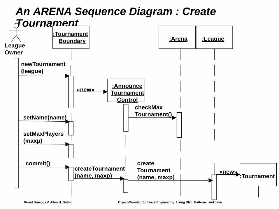
An ARENA Sequence Diagram : Create Tournament
League Owner
:TournamentBoundary
newTournament(league)
:AnnounceTournament
Control
«new»
setName(name)
setMaxPlayers(maxp)
commit()createTournament(name, maxp)
checkMaxTournament()
createTournament(name, maxp)
:Arena :League
:Tournament«new»

Bernd Bruegge & Allen H. Dutoit Object-Oriented Software Engineering: Using UML, Patterns, and Java 7
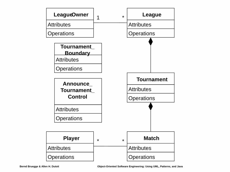
Impact on ARENA’s Object Model
♦ Let’s assume, before we formulated the previous sequence diagram, ARENA’s object model contained the objects
League Owner, Arena, League, Tournament, Match and Player
♦ The Sequence Diagram identified new ClassesTournament Boundary, Announce_Tournament_Control
Bernd Bruegge & Allen H. Dutoit Object-Oriented Software Engineering: Using UML, Patterns, and Java 8
AttributesOperations
League
AttributesOperations
Tournament
AttributesOperations
Player
AttributesOperations
Match
AttributesOperations
LeagueOwner 1 *
* *
AttributesOperations
Tournament_Boundary
AttributesOperations
Announce_Tournament_
Control

Bernd Bruegge & Allen H. Dutoit Object-Oriented Software Engineering: Using UML, Patterns, and Java 9
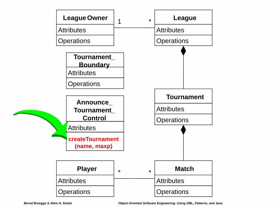
Impact on ARENA’s Object Model (ctd)
♦ The Sequence Diagram also supplied us with a lot of new events
newTournament(league)setName(name)setMaxPlayers(max)CommitcheckMaxTournaments()createTournament
♦ Question: Who owns these events?♦ Answer: For each object that receives an event there is a
public operation in the associated class.The name of the operation is usually the name of the event.

Bernd Bruegge & Allen H. Dutoit Object-Oriented Software Engineering: Using UML, Patterns, and Java 10
Example from the Sequence Diagram
createTournament(name, maxp)
createTournament(name, maxp)
League Owner
:TournamentBoundary
newTournament(league)
:AnnounceTournament
Control
«new»
setName(name)
setMaxPlayers(maxp)
commit()
checkMaxTournament()
:Arena :League
:Tournament«new»
createTournament is a (public)operation owned by
Announce_Tournament_Control
Bernd Bruegge & Allen H. Dutoit Object-Oriented Software Engineering: Using UML, Patterns, and Java 11
AttributesOperations
League
AttributesOperations
Tournament
AttributesOperations
Player
AttributesOperations
Match
AttributesOperations
League Owner 1 *
* *
AttributesOperations
Tournament_Boundary
AttributescreateTournament
(name, maxp)
Announce_Tournament_
Control

Bernd Bruegge & Allen H. Dutoit Object-Oriented Software Engineering: Using UML, Patterns, and Java 12
What else can we get out of sequence diagrams?
♦ Sequence diagrams are derived from the use cases. We therefore see the structure of the use cases.
♦ The structure of the sequence diagram helps us to determine how decentralized the system is.
♦ We distinguish two structures for sequence diagrams: Fork and Stair Diagrams (Ivar Jacobsen)

Bernd Bruegge & Allen H. Dutoit Object-Oriented Software Engineering: Using UML, Patterns, and Java 13
Heuristics for developing sequence diagrams
Bernd Bruegge & Allen H. Dutoit Object-Oriented Software Engineering: Using UML, Patterns, and Java 14
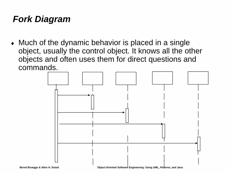
Fork Diagram
♦ Much of the dynamic behavior is placed in a single object, usually the control object. It knows all the other objects and often uses them for direct questions and commands.

Bernd Bruegge & Allen H. Dutoit Object-Oriented Software Engineering: Using UML, Patterns, and Java 15
Stair Diagram
♦ The dynamic behavior is distributed. Each object delegates some responsibility to other objects. Each object knows only a few of the other objects and knows which objects can help with a specific behavior.

Bernd Bruegge & Allen H. Dutoit Object-Oriented Software Engineering: Using UML, Patterns, and Java 16
Fork or Stair?
♦ Which of these diagram types should be chosen?♦ Object-oriented fans claim that the stair structure is
betterThe more the responsibility is spread out, the better
♦ However, this is not always true. Better heuristics:♦ Decentralized control structure
The operations have a strong connectionThe operations will always be performed in the same order
♦ Centralized control structure (better support of change)The operations can change orderNew operations can be inserted as a result of new requirements
These slides are designed to accompany Software Engineering: A Practitioner’s Approach, 7/e (McGraw-Hill 2009). Slides copyright 2009 by Roger Pressman.
Writing the Software Specification
Everyone knew exactly what had to be done until someone wrote it down!

These slides are designed to accompany Software Engineering: A Practitioner’s Approach, 7/e (McGraw-Hill 2009). Slides copyright 2009 by Roger Pressman.
Patterns for Requirements Modeling
Software patterns are a mechanism for capturing domain knowledge in a way that allows it to be reapplied when a new problem is encountered
domain knowledge can be applied to a new problem within the same application domainthe domain knowledge captured by a pattern can be applied by analogy to a completely different application domain.
The original author of an analysis pattern does not “create” the pattern, but rather, discovers it as requirements engineering work is being conducted. Once the pattern has been discovered, it is documented
These slides are designed to accompany Software Engineering: A Practitioner’s Approach, 7/e (McGraw-Hill 2009). Slides copyright 2009 by Roger Pressman.
Discovering Analysis Patterns
The most basic element in the description of a requirements model is the use case. A coherent set of use cases may serve as the basis for discovering one or more analysis patterns. A semantic analysis pattern (SAP) “is a pattern that describes a small set of coherent use cases that together describe a basic generic application.” [Fer00]

These slides are designed to accompany Software Engineering: A Practitioner’s Approach, 7/e (McGraw-Hill 2009). Slides copyright 2009 by Roger Pressman.
An ExampleConsider the following preliminary use case for software required to control and monitor a real-view camera and proximity sensor for an automobile:
Use case: Monitor reverse motionDescription: When the vehicle is placed in reverse gear, the control software enables a video feed from a rear-placed video camera to the dashboard display. The control software superimposes a variety of distance and orientation lines on the dashboard display so that the vehicle operator can maintain orientation as the vehicle moves in reverse. The control software also monitors a proximity sensor to determine whether an object is inside 10 feet of the rear of the vehicle. It will automatically break the vehicle if the proximity sensor indicates an object within 3 feet of the rear
of the vehicle.

These slides are designed to accompany Software Engineering: A Practitioner’s Approach, 7/e (McGraw-Hill 2009). Slides copyright 2009 by Roger Pressman.
An ExampleThis use case implies a variety of functionality that would be refined and elaborated (into a coherent set of use cases) during requirements gathering and modeling. Regardless of how much elaboration is accomplished, the use case(s) suggest(s) a simple, yet widely applicable SAP—the software-based monitoring and control of sensors and actuators in a physical system. In this case, the “sensors” provide information about proximity and video information. The “actuator” is the breaking system of the vehicle (invoked if an object is very close to the vehicle. But in a more general case, a widely applicable pattern is discovered --> Actuator-Sensor

These slides are designed to accompany Software Engineering: A Practitioner’s Approach, 7/e (McGraw-Hill 2009). Slides copyright 2009 by Roger Pressman.
Actuator-Sensor Pattern—IPattern Name: Actuator-SensorIntent: Specify various kinds of sensors and actuators in an embedded system.
Motivation: Embedded systems usually have various kinds of sensors and actuators. These sensors and actuators are all either directly or indirectly connected to a control unit. Although many of the sensors and actuators look quite different, their behavior is similar enough to structure them into a pattern. The pattern shows how to specify the sensors and actuators for a system, including attributes and operations. The Actuator-Sensor pattern uses a pull mechanism (explicit request for information) for PassiveSensors and a push mechanism (broadcast of information) for the ActiveSensors.
Constraints:Each passive sensor must have some method to read sensor input and attributes that represent the sensor value.
Each active sensor must have capabilities to broadcast update messages when its value changes.
Each active sensor should send a life tick, a status message issued within a specified time frame, to detect malfunctions.
Each actuator must have some method to invoke the appropriate response determined by theComputingComponent. Each sensor and actuator should have a function implemented to check its own operation state.
Each sensor and actuator should be able to test the validity of the values received or sent and set its operation state if the values are outside of the specifications.
These slides are designed to accompany Software Engineering: A Practitioner’s Approach, 7/e (McGraw-Hill 2009). Slides copyright 2009 by Roger Pressman.
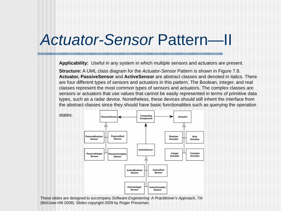
Actuator-Sensor Pattern—IIApplicability: Useful in any system in which multiple sensors and actuators are present.
Structure: A UML class diagram for the Actuator-Sensor Pattern is shown in Figure 7.8. Actuator, PassiveSensor and ActiveSensor are abstract classes and denoted in italics. There are four different types of sensors and actuators in this pattern. The Boolean, integer, and real classes represent the most common types of sensors and actuators. The complex classes are sensors or actuators that use values that cannot be easily represented in terms of primitive data types, such as a radar device. Nonetheless, these devices should still inherit the interface from the abstract classes since they should have basic functionalities such as querying the operation
states.

These slides are designed to accompany Software Engineering: A Practitioner’s Approach, 7/e (McGraw-Hill 2009). Slides copyright 2009 by Roger Pressman.
Actuator-Sensor Pattern—IIIBehavior: Figure 7.9 presents a UML sequence diagram for an example of the Actuator-SensorPattern as it might be applied for the SafeHome function that controls the positioning (e.g., pan, zoom) of a security camera. Here, the ControlPanel queries a sensor (a passive position sensor) and an actuator (pan control) to check the operation state for diagnostic purposes before reading or setting a value. The messages Set Physical Value and Get Physical Value are not messages between objects. Instead, they describe the interaction between the physical devices of the system and their software counterparts. In the lower part of the diagram, below the horizontal line, the PositionSensor reports that the operation state is zero. The ComputingComponent then sends the error code for a position sensor failure to the FaultHandler that will decide how this error affects the system and what actions are required. it gets the data from the sensors and computes the required response for the actuators.

These slides are designed to accompany Software Engineering: A Practitioner’s Approach, 7/e (McGraw-Hill 2009). Slides copyright 2009 by Roger Pressman.
Actuator-Sensor Pattern—IIISee SEPA, 7/e for additional information on:
ParticipantsCollaborationsConsequences
These slides are designed to accompany Software Engineering: A Practitioner’s Approach, 7/e (McGraw-Hill 2009). Slides copyright 2009 by Roger Pressman.
Requirements Modeling for WebApps
Content Analysis. The full spectrum of content to be provided by the WebApp is identified, including text, graphics and images, video, and audio data. Data modeling can be used to identify and describe each of the data objects.
Interaction Analysis. The manner in which the user interacts with the WebApp is described in detail. Use-cases can be developed to provide detailed descriptions of this interaction.
Functional Analysis. The usage scenarios (use-cases) created as part of interaction analysis define the operations that will be applied to WebApp content and imply other processing functions. All operations and functions are described in detail.
Configuration Analysis. The environment and infrastructure in which the WebApp resides are described in detail.

These slides are designed to accompany Software Engineering: A Practitioner’s Approach, 7/e (McGraw-Hill 2009). Slides copyright 2009 by Roger Pressman.
When Do We Perform Analysis?In some WebE situations, analysis and design merge. However, an explicit analysis activity occurs when …
the WebApp to be built is large and/or complexthe number of stakeholders is largethe number of Web engineers and other contributors is largethe goals and objectives (determined during formulation) for the WebApp will effect the business’ bottom linethe success of the WebApp will have a strong bearing on the success of the business
These slides are designed to accompany Software Engineering: A Practitioner’s Approach, 7/e (McGraw-Hill 2009). Slides copyright 2009 by Roger Pressman.
The Content ModelContent objects are extracted from use-cases
examine the scenario description for direct and indirect references to content
Attributes of each content object are identifiedThe relationships among content objects and/or the hierarchy of content maintained by a WebApp
Relationships—entity-relationship diagram or UMLHierarchy—data tree or UML
These slides are designed to accompany Software Engineering: A Practitioner’s Approach, 7/e (McGraw-Hill 2009). Slides copyright 2009 by Roger Pressman.
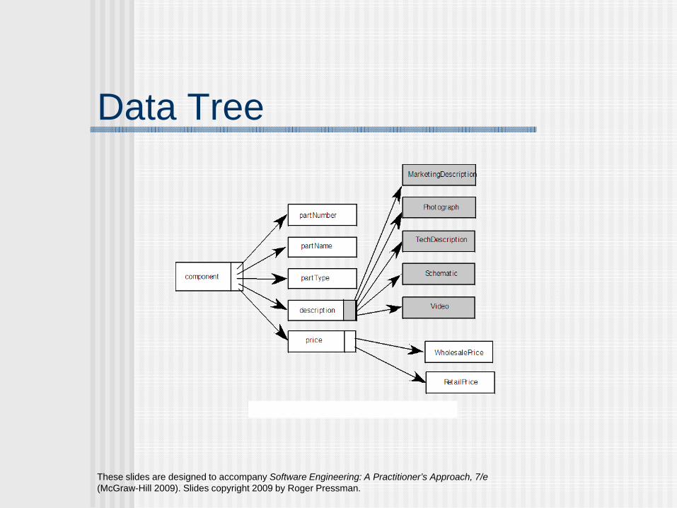
Data Tree

These slides are designed to accompany Software Engineering: A Practitioner’s Approach, 7/e (McGraw-Hill 2009). Slides copyright 2009 by Roger Pressman.
The Interaction ModelComposed of four elements:
use-casessequence diagramsstate diagrams a user interface prototype
Each of these is an important UML notation and is described in Appendix I

These slides are designed to accompany Software Engineering: A Practitioner’s Approach, 7/e (McGraw-Hill 2009). Slides copyright 2009 by Roger Pressman.
Sequence Diagram

These slides are designed to accompany Software Engineering: A Practitioner’s Approach, 7/e (McGraw-Hill 2009). Slides copyright 2009 by Roger Pressman.
State Diagram

These slides are designed to accompany Software Engineering: A Practitioner’s Approach, 7/e (McGraw-Hill 2009). Slides copyright 2009 by Roger Pressman.
The Functional ModelThe functional model addresses two processing elements of the WebApp
user observable functionality that is delivered by the WebApp to end-usersthe operations contained within analysis classes that implement behaviors associated with the class.
An activity diagram can be used to represent processing flow

These slides are designed to accompany Software Engineering: A Practitioner’s Approach, 7/e (McGraw-Hill 2009). Slides copyright 2009 by Roger Pressman.
Activity Diagram
These slides are designed to accompany Software Engineering: A Practitioner’s Approach, 7/e (McGraw-Hill 2009). Slides copyright 2009 by Roger Pressman.
The Configuration ModelServer-side
Server hardware and operating system environment must be specifiedInteroperability considerations on the server-side must be consideredAppropriate interfaces, communication protocols and related collaborative information must be specified
Client-sideBrowser configuration issues must be identifiedTesting requirements should be defined

These slides are designed to accompany Software Engineering: A Practitioner’s Approach, 7/e (McGraw-Hill 2009). Slides copyright 2009 by Roger Pressman.
Navigation Modeling-IShould certain elements be easier to reach (require fewer navigation steps) than others? What is the priority for presentation?Should certain elements be emphasized to force users to navigate in their direction?How should navigation errors be handled?Should navigation to related groups of elements be given priority over navigation to a specific element. Should navigation be accomplished via links, via search-based access, or by some other means?Should certain elements be presented to users based on the context of previous navigation actions?Should a navigation log be maintained for users?
These slides are designed to accompany Software Engineering: A Practitioner’s Approach, 7/e (McGraw-Hill 2009). Slides copyright 2009 by Roger Pressman.
Navigation Modeling-IIShould a full navigation map or menu (as opposed to a single “back” link or directed pointer) be available at every point in a user’s interaction?Should navigation design be driven by the most commonly expected user behaviors or by the perceived importance of the defined WebApp elements?Can a user “store” his previous navigation through the WebApp to expedite future usage?For which user category should optimal navigation be designed?How should links external to the WebApp be handled? overlaying the existing browser window? as a new browser window? as a separate frame?

Bernd Bruegge & Allen H. Dutoit Object-Oriented Software Engineering: Using UML, Patterns, and Java 31
♦ 1. What are the transformations? Create scenarios and use case diagrams
Talk to client, observe, get historical records, do thought experiments
2. What is the structure of the system?Create class diagrams
Identify objects. What are the associations between them? What is their multiplicity?What are the attributes of the objects?What operations are defined on the objects?
3. What is its behavior? Create sequence diagrams
Identify senders and receiversShow sequence of events exchanged between objects. Identify event dependencies and event concurrency.
Create state diagrams Only for the dynamically interesting objects.
Summary: Requirements Analysis
Dynamic Modeling
Functional Modeling
Object Modeling

Bernd Bruegge & Allen H. Dutoit Object-Oriented Software Engineering: Using UML, Patterns, and Java 32
Let’s Do Analysis
1. Analyze the problem statementIdentify functional requirementsIdentify nonfunctional requirementsIdentify constraints (pseudo requirements)
2. Build the functional model: Develop use cases to illustrate functionality requirements
3. Build the dynamic model:Develop sequence diagrams to illustrate the interaction between objectsDevelop state diagrams for objects with interesting behavior
4. Build the object model: Develop class diagrams showing the structure of the system

Bernd Bruegge & Allen H. Dutoit Object-Oriented Software Engineering: Using UML, Patterns, and Java 33
Problem Statement: Direction Control for a Toy Car
♦ Power is turned onCar moves forward and car headlight shines
♦ Power is turned offCar stops and headlight goes out.
♦ Power is turned onHeadlight shines
♦ Power is turned offHeadlight goes out.
♦ Power is turned onCar runs backward with its headlight shining.
♦ Power is turned offCar stops and headlight goes out.
♦ Power is turned onHeadlight shines
♦ Power is turned offHeadlight goes out.
♦ Power is turned onCar runs forward with its headlight shining.

Bernd Bruegge & Allen H. Dutoit Object-Oriented Software Engineering: Using UML, Patterns, and Java 34
Find the Functional Model: Do Use Case Modeling♦ Use case 1: System Initialization
Entry condition: Power is off, car is not movingFlow of events:
Driver turns power onExit condition: Car moves forward, headlight is on
♦ Use case 2: Turn headlight offEntry condition: Car moves forward with headlights onFlow of events:
Driver turns power off, car stops and headlight goes out. Driver turns power on, headlight shines and car does not move. Driver turns power off, headlight goes out
Exit condition: Car does not move, headlight is out

Bernd Bruegge & Allen H. Dutoit Object-Oriented Software Engineering: Using UML, Patterns, and Java 35
Use Cases continued♦ Use case 3: Move car backward
Entry condition: Car is stationary, headlights offFlow of events:
Driver turns power onExit condition: Car moves backward, headlight on
♦ Use case 4: Stop backward moving carEntry condition: Car moves backward, headlights onFlow of events:
Driver turns power off, car stops, headlight goes out. Power is turned on, headlight shines and car does not move. Power is turned off, headlight goes out.
Exit condition: Car does not move, headlight is out.♦ Use case 5: Move car forward
Entry condition: Car does not move, headlight is outFlow of events
Driver turns power onExit condition:
Car runs forward with its headlight shining.
Bernd Bruegge & Allen H. Dutoit Object-Oriented Software Engineering: Using UML, Patterns, and Java 36
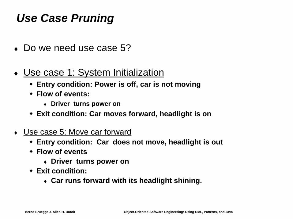
Use Case Pruning
♦ Do we need use case 5?
♦ Use case 1: System InitializationEntry condition: Power is off, car is not movingFlow of events:
Driver turns power onExit condition: Car moves forward, headlight is on
♦ Use case 5: Move car forwardEntry condition: Car does not move, headlight is outFlow of events
Driver turns power onExit condition:
Car runs forward with its headlight shining.

Bernd Bruegge & Allen H. Dutoit Object-Oriented Software Engineering: Using UML, Patterns, and Java 37
Find the Dynamic Model: Create sequence diagram
♦ Name: Drive Car♦ Sequence of events:
Billy turns power onHeadlight goes onWheels starts moving forwardWheels keeps moving forwardBilly turns power offHeadlight goes offWheels stops moving. . .

Bernd Bruegge & Allen H. Dutoit Object-Oriented Software Engineering: Using UML, Patterns, and Java 38
Sequence Diagram for Drive Car Scenario
:Headlight Billy:Driver :Wheel
Power(on) Power(on)
Power(off) Power(off)
Power(on) Power(on)

Bernd Bruegge & Allen H. Dutoit Object-Oriented Software Engineering: Using UML, Patterns, and Java 39
Toy Car: Dynamic ModelWheel
Forward
Backward
Stationary Stationary
poweron
poweroff
poweroff
poweron
Headlight
poweronpower
off
Off
On
Bernd Bruegge & Allen H. Dutoit Object-Oriented Software Engineering: Using UML, Patterns, and Java 40
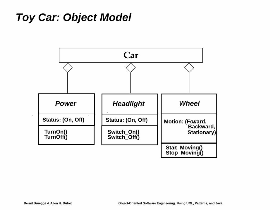
Toy Car: Object Model
Wheel
Motion: (Forward,
Stationary)Backward,
Start_Moving()Stop_Moving()
Headlight
Status: (On, Off)
Switch_On()Switch_Off()
Power
Status: (On, Off)
TurnOn()TurnOff()
Car

Bernd Bruegge & Allen H. Dutoit Object-Oriented Software Engineering: Using UML, Patterns, and Java 41
When is a model dominant?♦ Object model: The system has objects with nontrivial state.♦ Dynamic model: The model has many different types of
events: Input, output, exceptions, errors, etc.♦ Functional model: The model performs complicated
transformations (e.g. computations consisting of many steps).
♦ Which of these models is dominant in the following three cases?
CompilerDatabase systemSpreadsheet program

Bernd Bruegge & Allen H. Dutoit Object-Oriented Software Engineering: Using UML, Patterns, and Java 42
Dominance of models♦ Compiler:
The functional model most important. (Why?)The dynamic model is trivial because there is only one type input and only a few outputs.
♦ Database systems:The object model most important. The functional model is trivial, because the purpose of the functions is usually to store, organize and retrieve data.
♦ Spreadsheet program:The functional model most important. The dynamic model is interesting if the program allows computations on a cell.The object model is trivial, because the spreadsheet values are trivial and cannot be structured further. The only interesting object is the cell.
Bernd Bruegge & Allen H. Dutoit Object-Oriented Software Engineering: Using UML, Patterns, and Java 43
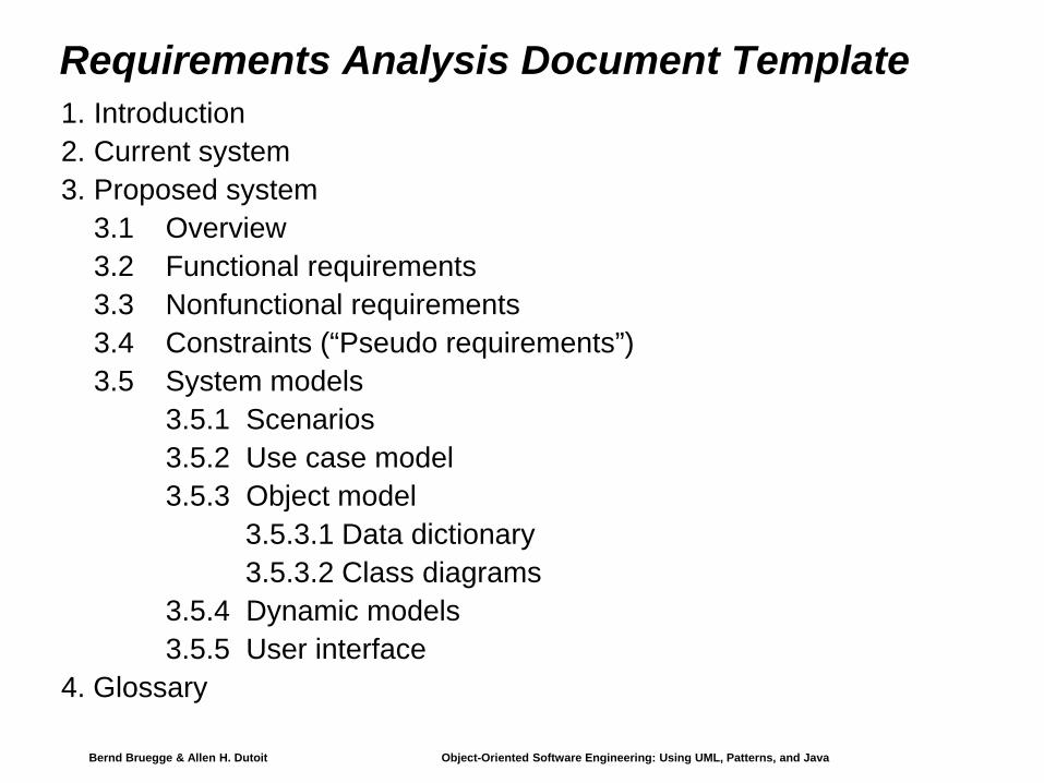
Requirements Analysis Document Template1. Introduction2. Current system3. Proposed system
3.1 Overview3.2 Functional requirements3.3 Nonfunctional requirements3.4 Constraints (“Pseudo requirements”) 3.5 System models
3.5.1 Scenarios3.5.2 Use case model3.5.3 Object model
3.5.3.1 Data dictionary3.5.3.2 Class diagrams
3.5.4 Dynamic models3.5.5 User interface
4. Glossary
Bernd Bruegge & Allen H. Dutoit Object-Oriented Software Engineering: Using UML, Patterns, and Java 44
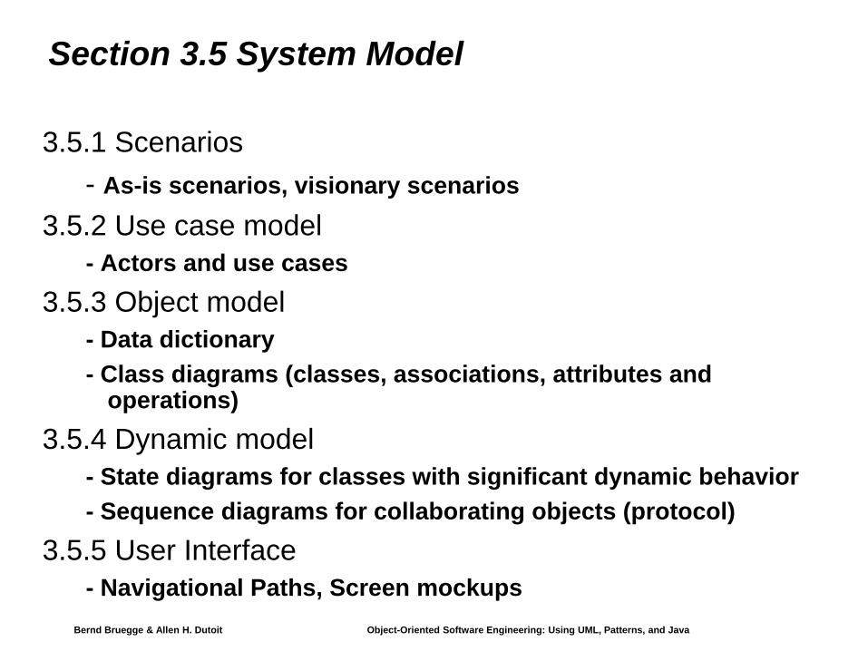
Section 3.5 System Model
3.5.1 Scenarios- As-is scenarios, visionary scenarios
3.5.2 Use case model- Actors and use cases
3.5.3 Object model - Data dictionary- Class diagrams (classes, associations, attributes and
operations)3.5.4 Dynamic model
- State diagrams for classes with significant dynamic behavior- Sequence diagrams for collaborating objects (protocol)
3.5.5 User Interface- Navigational Paths, Screen mockups

Bernd Bruegge & Allen H. Dutoit Object-Oriented Software Engineering: Using UML, Patterns, and Java 45
Section 3.3 Nonfunctional Requirements
3.3.1 User interface and human factors3.3.2 Documentation3.3.3 Hardware considerations3.3.4 Performance characteristics3.3.5 Error handling and extreme conditions3.3.6 System interfacing3.3.7 Quality issues3.3.8 System modifications3.3.9 Physical environment3.3.10 Security issues3.3.11 Resources and management issues

Bernd Bruegge & Allen H. Dutoit Object-Oriented Software Engineering: Using UML, Patterns, and Java 46
Nonfunctional Requirements: Trigger Questions3.3.1 User interface and human factors
What type of user will be using the system?Will more than one type of user be using the system?What sort of training will be required for each type of user?Is it particularly important that the system be easy to learn?Is it particularly important that users be protected from making errors?What sort of input/output devices for the human interface are available, and what are their characteristics?
3.3.2 DocumentationWhat kind of documentation is required?What audience is to be addressed by each document?
3.3.3 Hardware considerationsWhat hardware is the proposed system to be used on?What are the characteristics of the target hardware, including memory size and auxiliary storage space?
Bernd Bruegge & Allen H. Dutoit Object-Oriented Software Engineering: Using UML, Patterns, and Java 47
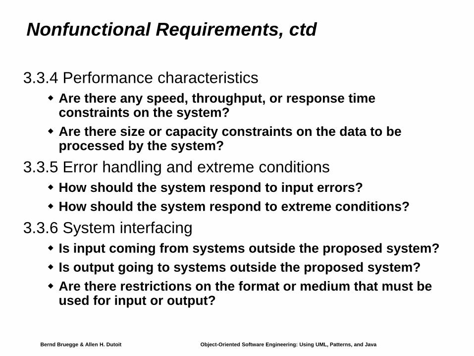
Nonfunctional Requirements, ctd
3.3.4 Performance characteristicsAre there any speed, throughput, or response time constraints on the system?Are there size or capacity constraints on the data to be processed by the system?
3.3.5 Error handling and extreme conditionsHow should the system respond to input errors?How should the system respond to extreme conditions?
3.3.6 System interfacingIs input coming from systems outside the proposed system?Is output going to systems outside the proposed system?Are there restrictions on the format or medium that must be used for input or output?

Bernd Bruegge & Allen H. Dutoit Object-Oriented Software Engineering: Using UML, Patterns, and Java 48
Nonfunctional Requirements, ctd♦ 3.3.7 Quality issues
What are the requirements for reliability?Must the system trap faults?What is the maximum time for restarting the system after a failure?What is the acceptable system downtime per 24-hour period?Is it important that the system be portable (able to move to different hardware or operating system environments)?
♦ 3.3.8 System ModificationsWhat parts of the system are likely candidates for later modification?What sorts of modifications are expected?
♦ 3.3.9 Physical EnvironmentWhere will the target equipment operate?Will the target equipment be in one or several locations?Will the environmental conditions in any way be out of the ordinary (for example, unusual temperatures, vibrations, magnetic fields, ...)?

Bernd Bruegge & Allen H. Dutoit Object-Oriented Software Engineering: Using UML, Patterns, and Java 49
Nonfunctional Requirements, ctd
♦ 3.3.10 Security IssuesMust access to any data or the system itself be controlled?Is physical security an issue?
♦ 3.3.11 Resources and Management Issues How often will the system be backed up?Who will be responsible for the back up?Who is responsible for system installation?Who will be responsible for system maintenance?
Bernd Bruegge & Allen H. Dutoit Object-Oriented Software Engineering: Using UML, Patterns, and Java 50
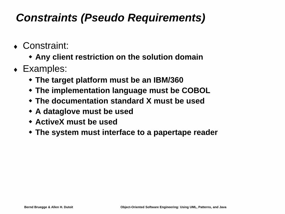
Constraints (Pseudo Requirements)
♦ Constraint: Any client restriction on the solution domain
♦ Examples:The target platform must be an IBM/360The implementation language must be COBOLThe documentation standard X must be usedA dataglove must be usedActiveX must be usedThe system must interface to a papertape reader