chapter 7 power supply arrangement
TRANSCRIPT

1/15
DETAILED PROJECT REPORT FOR PUNE METRO March 2009
CHAPTER 7
POWER SUPPLY ARRANGEMENT
7.1.1 POWER REQUIREMENTS
Electricity is required for operation of Metro system for running of trains, station
services (e.g. lighting, lifts, escalators, signalling & telecom, fire fighting etc) and
workshops, depots & other maintenance infrastructure within premises of metro
system. The power requirements of a metro system are determined by peak-hour
demands of power for traction and auxiliary applications. Broad estimation of
auxiliary and traction power demand is made based on the following
requirements:-
(i) Specific energy consumption of rolling stock – 70KWh/1000 GTKM
(ii) Regeneration by rolling stock – 30%
(iii) Elevated station load – initially 200KW, which will increase to 500 KW in
the year 2031
(iv) Underground Station load – initially 2000 kW, which will increase to 2500
kW in the year 2031
(v) Depot auxiliary load - initially 1000KW, which will increase to 2000 KW in
the year 2031
CHAPTER 7 – POWER SUPPLY ARRANGEMENT
2/15
DETAILED PROJECT REPORT FOR PUNE METRO March 2009
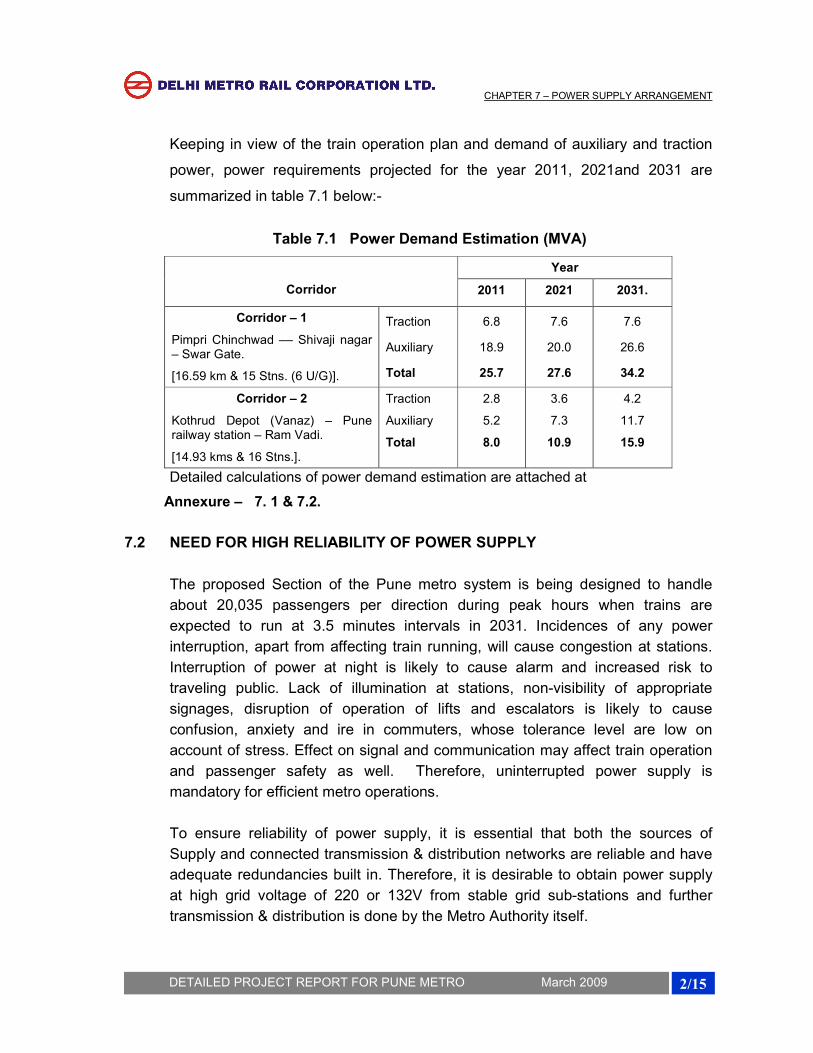
Keeping in view of the train operation plan and demand of auxiliary and traction
power, power requirements projected for the year 2011, 2021and 2031 are
summarized in table 7.1 below:-
Table 7.1 Power Demand Estimation (MVA)
Corridor
Year
2011 2021 2031.
Corridor – 1
Pimpri Chinchwad –– Shivaji nagar – Swar Gate.
[16.59 km & 15 Stns. (6 U/G)].
Traction
Auxiliary
Total
6.8
18.9
25.7
7.6
20.0
27.6
7.6
26.6
34.2
Corridor – 2
Kothrud Depot (Vanaz) – Pune railway station – Ram Vadi.
[14.93 kms & 16 Stns.].
Traction
Auxiliary
Total
2.8
5.2
8.0
3.6
7.3
10.9
4.2
11.7
15.9
Detailed calculations of power demand estimation are attached at
Annexure – 7. 1 & 7.2.
7.2 NEED FOR HIGH RELIABILITY OF POWER SUPPLY
The proposed Section of the Pune metro system is being designed to handle
about 20,035 passengers per direction during peak hours when trains are
expected to run at 3.5 minutes intervals in 2031. Incidences of any power
interruption, apart from affecting train running, will cause congestion at stations.
Interruption of power at night is likely to cause alarm and increased risk to
traveling public. Lack of illumination at stations, non-visibility of appropriate
signages, disruption of operation of lifts and escalators is likely to cause
confusion, anxiety and ire in commuters, whose tolerance level are low on
account of stress. Effect on signal and communication may affect train operation
and passenger safety as well. Therefore, uninterrupted power supply is
mandatory for efficient metro operations.
To ensure reliability of power supply, it is essential that both the sources of
Supply and connected transmission & distribution networks are reliable and have
adequate redundancies built in. Therefore, it is desirable to obtain power supply
at high grid voltage of 220 or 132V from stable grid sub-stations and further
transmission & distribution is done by the Metro Authority itself.

CHAPTER 7 – POWER SUPPLY ARRANGEMENT
3/15
DETAILED PROJECT REPORT FOR PUNE METRO March 2009
7.3 SOURCES OF POWER SUPPLY
The high voltage power supply network of Pune city has 220kV and 132kV and
network to cater to various types of demand in vicinity of the proposed corridor.
220 kV Sub Stations are generally located at outskirts of the city. 220/132 kV sub
stations and some 132 KV Transmission lines are located /passing near to the
alignment of Corridors. Keeping in view the reliability requirements, two input
sources of 132 kV Voltage level are normally considered for each corridor.
Accordingly, two Receiving Sub Stations (132 / 33/25 kV) are proposed to be set
up for Corridor I & Corridor –II each. Based on the discussions with Pune power
supply authorities, it is proposed to avail power supply for traction as well as
auxiliary services from the following grid sub-stations at 132 kV voltage through
double cable feeders. The input sources for these four grid sub stations are
different therefore the reliability enhances further: Sources of power supply is
given in Table 7.2.
Table 7.2 Sources of Power Supply
Corridor Grid sub-station (with Input voltage)
Location of RSS of Metro Authority
Approx. length of cables
Corridor – I
Pimpri Chinchwad – Shivaji nagar –
Swar Gate.
Chinchwad GSS
(220 / 132kV)
Near PCMC
(132 / 33/25 kV).
5km. 132kV
(Double Circuit cables).
Ganesh Khind Grid Sub Station (220 / 132 kV).
RSS near Agriculture College
(132 / 33/25 kV)
2.5km. 132kV
(Double Circuit cables).
Corridor – II
Kothrud Depot (Vanaz) –Pune railway station- Ram Vadi.
BY LILO From 132 KV transmission line at Kothrud
Near Kachara Depot
(132 / 33/25 kV)
2.5 km. 132kV
(Double Circuit Cables).
Khardi Grid Sub Station
(220 / 132 kV).
Near Ram Vadi
(132 / 33/25 kV)
3 km. 132kV
(Double Circuit
Cables).
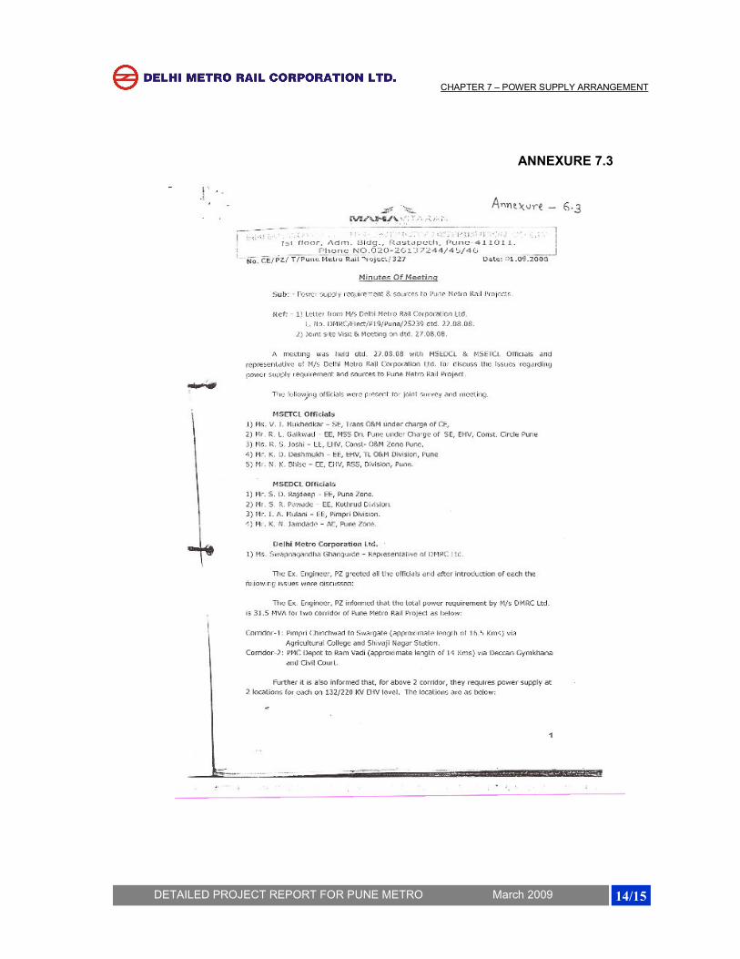
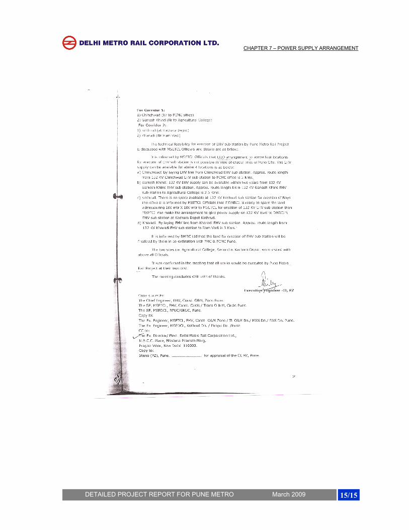
Summary of expected power demand at various sources is given in Table – 7.3.
Maharashtra state Electricity Distribution Co. Ltd. have confirmed availability of
requisite power at their above sub-stations vide letter No CE/PZ/T/Pune Metro
Rail Project/327dated:-01.09.2008 (Annexure 7.3).

CHAPTER 7 – POWER SUPPLY ARRANGEMENT
4/15
DETAILED PROJECT REPORT FOR PUNE METRO March 2009
Table 7.3 Power Demand Projection for various sources.
Corridor Input Source Peak Demand – Normal (MVA)
Peak Demand – Emergency (MVA)
2011 2031 2011 2031
Corridor – I Pimpri Chinchwad –
Shivaji nagar – Swar Gate
RSS Near PCMC office
Traction 3.8 4.3 6.8 7.6
Auxiliary 2.2 5.6 18.9 26.6
Sub – Total (A) 6.0 9.9 25.7 34.2
RSS near Agriculture College
Traction 3.0 3.3 6.8 7.6
Auxiliary 16.7 21.0 18.9 26.6
Sub – Total (B) 19.7 24.3 25.7 34.2
TOTAL (A + B) 25.7 34.2
Corridor – II Kothrud Depot (Vanaz) –Pune railway station- Ram Vadi.
RSS near Kachara Depot
Traction 2.0 2.7 2.8 4.2
Auxiliary 3.2 6.8 5.2 11.7
Total 5.2 9.5 8.0 15.9
RSS Near Ramvadi
Traction 0.8 1.5 2.8 4.2
Auxiliary 2.0 4.9 5.2 11.7
Total 2.8 6.4 8.0 15.9
TOTAL (A + B) 8.0 15.9
The 132 kV power supply will be stepped down to 25kV single phase for traction
purpose at the RSS of Pune Metro and the 25kV traction supply will be fed to the
OHE at viaduct through cable feeders. For feeding the auxiliary loads, the 132 kV
power supply received will be stepped down to 33 kV and will be distributed along
the alignment through 33kV Ring main cable network. These cables will be laid in
dedicated ducts along the viaduct / on tunnel walls. If one RSS trips on fault or
input supply failure, train services can be maintained from the other RSS.
However, in case of total grid failure, all trains may come to a halt but station
lighting & other essential services can be catered to by stand-by DG sets.
Therefore, while the proposed scheme is expected to ensure adequate reliability,
it would cater to emergency situations as well.

CHAPTER 7 – POWER SUPPLY ARRANGEMENT
5/15
DETAILED PROJECT REPORT FOR PUNE METRO March 2009
Typical High Voltage Receiving Sub-Station
The 132kV cables will be laid through public pathways from Maharastra State
Electricity Distribution Co. Ltd. Sub-stations to RSS of Metro Authority. For
corridor-I, RSS Near PCMC and near Agriculture College shall be provided with
2nos. (one as standby) 132/25 kV, 10 MVA single-phase traction Transformers
for feeding Traction and 132/33 KV, 30 MVA three phase Transformers for
feeding auxiliary loads. For corridor – II, RSS Near Kachara depot and RSS near
Ram Vadi shall be provided with 2nos. (one as standby) 132/25 kV, 10 MVA
single phase traction Transformers for feeding Traction supply and 132/33 KV, 15
MVA three phase Transformers for feeding auxiliary loads. The capacity of
transformers may be reviewed considering the load requirement/distribution of
both the corridors at the time of detailed design.
Conventional Outdoor type 132 kV Switchgear is proposed for above Four RSS’s
to be located in approx. 100 X 60 m (6000 sq. mm) land plot, as the availability of
Land in this area may not be a constraint.
CHAPTER 7 – POWER SUPPLY ARRANGEMENT
6/15
DETAILED PROJECT REPORT FOR PUNE METRO March 2009
7.4 AUXILIARY SUPPLY ARRANGEMENTS FOR STATIONS & DEPOT
Auxiliary sub-stations (ASS) are envisaged to be provided at each station (3
ASS’s for Underground stations and 1 ASS for elevated station) for stepping
down 33 kV supply to 415 V for auxiliary applications. A separate ASS is required
at depot. The ASS will be located at mezzanine or platform level inside a room.
The auxiliary load requirements have been assessed at 200kW for elevated / at-
grade stations which is likely to increase up to 500 KW in the year 2031 and 2000
kW for Underground Station which is likely to increase up to 2500 KW in the year
2031. In order to meet the requirement of auxiliary power two dry type cast resin
transformers (33/0.415kV) of 500kVA capacity are proposed to be installed at the
elevated stations (one transformer as standby) and one transformer of 1.6 MVA
at each underground ASS. For Property Development within the footprints of the
station, a provision to add third transformer at a later date may be kept at
elevated station
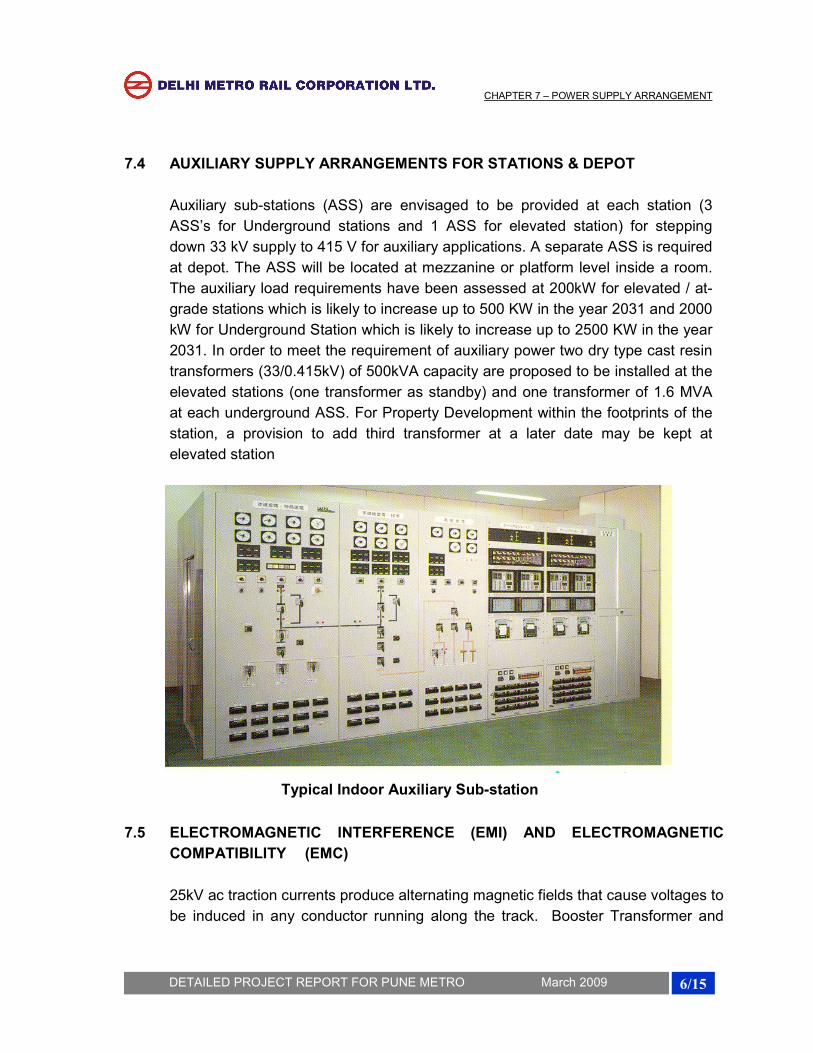
Typical Indoor Auxiliary Sub-station
7.5 ELECTROMAGNETIC INTERFERENCE (EMI) AND ELECTROMAGNETIC
COMPATIBILITY (EMC)
25kV ac traction currents produce alternating magnetic fields that cause voltages to
be induced in any conductor running along the track. Booster Transformer and
CHAPTER 7 – POWER SUPPLY ARRANGEMENT
7/15
DETAILED PROJECT REPORT FOR PUNE METRO March 2009
Return Conductor (BT/RC) System is proposed for EMI mitigation. Concrete
structures of elevated viaducts are not good electrical earths and therefore,
Earthing and Bonding of the traction system shall be in accordance with the latest
standards EN50122-1, IEEE80 and other relevant standards. Two earth
conductors –Overhead Protection Cable (OPC) and Buried Earth Conductor (BEC)
are proposed to be laid along with elevated via duct and all the metallic structures,
structural reinforcement, running rails etc will be connected to these conductors to
form an equiv-potential surface & a least resistance path to the fault currents. The
overhead protection cable will also provide protection against lightning to the 25kV
OHE and the elevated viaduct. Similar arrangements have been adopted on Delhi
Metro as well.
Detailed specification of equipment e.g. power cables, transformer, switchgear,
E&M equipment etc shall be framed to reduce conducted or radiated emissions as
per appropriate international standards. The Metro system as a whole (trains,
signaling & telecomm, traction power supply, E&M system etc) shall comply with
the EMC requirements of international standards viz. EN50121, EN50123,
IEC61000 series etc. A detailed EMI/EMC plan will be required to be developed
during project implementation stage.
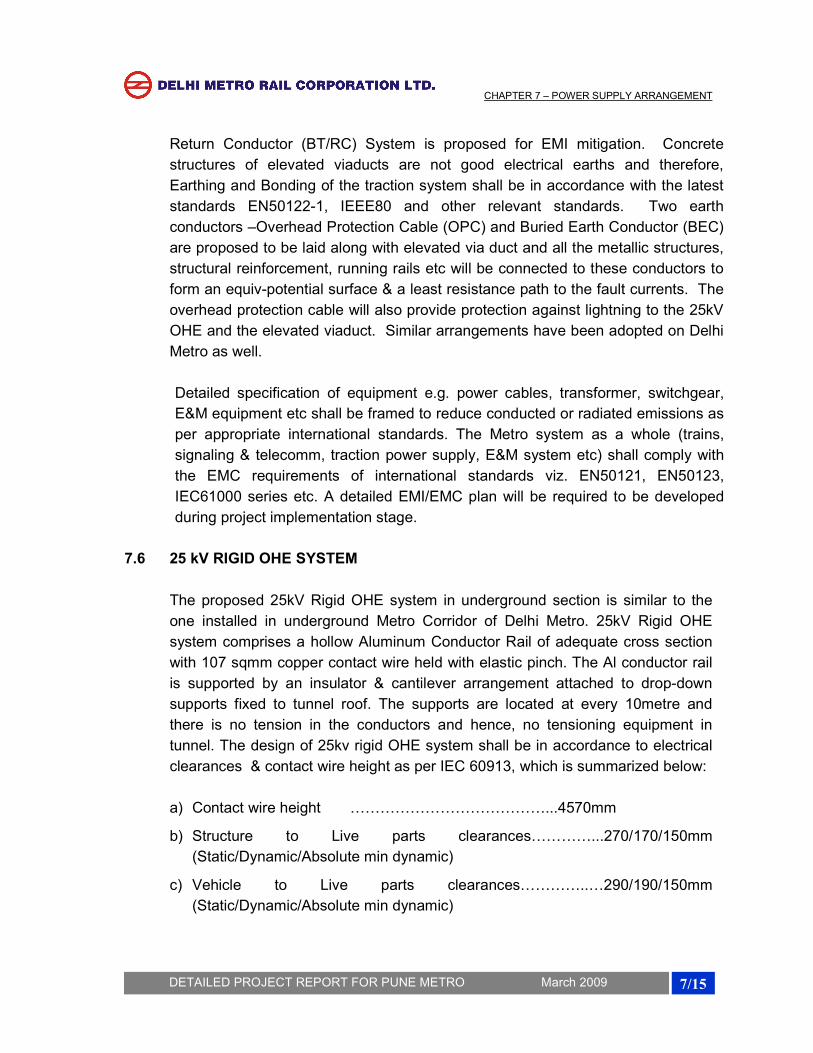
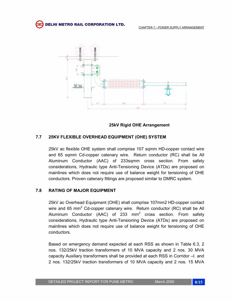
7.6 25 kV RIGID OHE SYSTEM
The proposed 25kV Rigid OHE system in underground section is similar to the
one installed in underground Metro Corridor of Delhi Metro. 25kV Rigid OHE
system comprises a hollow Aluminum Conductor Rail of adequate cross section
with 107 sqmm copper contact wire held with elastic pinch. The Al conductor rail
is supported by an insulator & cantilever arrangement attached to drop-down
supports fixed to tunnel roof. The supports are located at every 10metre and
there is no tension in the conductors and hence, no tensioning equipment in
tunnel. The design of 25kv rigid OHE system shall be in accordance to electrical
clearances & contact wire height as per IEC 60913, which is summarized below:
a) Contact wire height …………………………………...4570mm
b) Structure to Live parts clearances…………...270/170/150mm
(Static/Dynamic/Absolute min dynamic)
c) Vehicle to Live parts clearances…………..…290/190/150mm
(Static/Dynamic/Absolute min dynamic)
CHAPTER 7 – POWER SUPPLY ARRANGEMENT
8/15
DETAILED PROJECT REPORT FOR PUNE METRO March 2009
25kV Rigid OHE Arrangement
7.7 25KV FLEXIBLE OVERHEAD EQUIPMENT (OHE) SYSTEM
25kV ac flexible OHE system shall comprise 107 sqmm HD-copper contact wire
and 65 sqmm Cd-copper catenary wire. Return conductor (RC) shall be All
Aluminum Conductor (AAC) of 233sqmm cross section. From safety
considerations, Hydraulic type Anti-Tensioning Device (ATDs) are proposed on
mainlines which does not require use of balance weight for tensioning of OHE
conductors. Proven catenary fittings are proposed similar to DMRC system.
7.8 RATING OF MAJOR EQUIPMENT
25kV ac Overhead Equipment (OHE) shall comprise 107mm2 HD-copper contact
wire and 65 mm2 Cd-copper catenary wire. Return conductor (RC) shall be All
Aluminum Conductor (AAC) of 233 mm2 cross section. From safety
considerations, Hydraulic type Anti-Tensioning Device (ATDs) are proposed on
mainlines which does not require use of balance weight for tensioning of OHE
conductors.
Based on emergency demand expected at each RSS as shown in Table 6.3, 2
nos. 132/25kV traction transformers of 10 MVA capacity and 2 nos. 30 MVA
capacity Auxiliary transformers shall be provided at each RSS in Corridor –I. and
2 nos. 132/25kV traction transformers of 10 MVA capacity and 2 nos. 15 MVA
CHAPTER 7 – POWER SUPPLY ARRANGEMENT
9/15
DETAILED PROJECT REPORT FOR PUNE METRO March 2009
capacity Auxiliary transformers shall be provided at each RSS in Corridor –II,
being standard design (one to be in service and second one to serve as standby).
The 132kV incoming cable shall be 3-phase single core XLPE insulated with 630
mm2 Aluminum conductor to meet the normal & emergency loading requirements
and fault level of the 132 kV supply.
33kV and 25kV switchgear shall be rated for 1250 A being standard design. 33kV
cable ring network shall be adequately rated to transfer requisite auxiliary power
during normal as well as emergency situations and accordingly 3 number of
Single core 300 mm2 XLPE insulated 33kV cable is proposed for ring main
network. [FRLSOH Copper conductor cable for Corridor 1 with underground
section and FRLS Aluminum conductor Cable for Corridor 2 with fully Elevated
section].
Adequate no. of cables are required for transfer of traction power from Metro’s
RSS to 25kV OHE. Single-phase XLPE insulated cables with 240mm2 copper
conductor are proposed for traction power. Based on current requirements, 2
cables are required for each of the two circuits to feed power to OHE.
The above capacities of transformers, switchgear, cables etc. have been worked
out based on the conceptual design. Therefore, these may be required to be
revised for better accuracy during design stage of project implementation.
7.9 STANDBY DIESEL GENERATOR (DG) SETS
In the unlikely event of simultaneous tripping of all the input power sources or grid
failure, the power supply to stations as well as to trains will be interrupted. It is,
therefore, proposed to provide a standby DG set of 200 KVA capacity at the
elevated stations and 2 X 1000/750 KVA at Underground stations to cater to the
following essential services:
(i) Essential lighting
(ii) Signaling & telecommunications
(iii) Fire fighting system
(iv) Lift operation
(v) Fare collection system
(vi) Tunnel Ventilation (for Underground Stations)
CHAPTER 7 – POWER SUPPLY ARRANGEMENT
10/15
DETAILED PROJECT REPORT FOR PUNE METRO March 2009
Silent type DG sets with low noise levels are proposed, which do not require a
separate room for installation.
7.10 SUPERVISORY CONTROL AND DATA ACQUISITION (SCADA) SYSTEM
The entire system of power supply (receiving, traction & auxiliary supply) shall be
monitored and controlled from a centralized Operation Control Centre (OCC)
through SCADA system. Modern SCADA system with intelligent remote terminal
units (RTUs) shall be provided. Optical fibre provided for telecommunications will
be used as communication carrier for SCADA system.
Digital Protection Control System (DPCS) is proposed for providing data
acquisition, data processing, overall protection control, interlocking, inter-tripping
and monitoring of the entire power supply system consisting of 33kV ac
switchgear, transformers, 25kV ac switchgear and associated electrical
equipment. DPCS will utilize microprocessor-based fast-acting numerical relays &
Programmable Logic Controllers (PLCs) with suitable interface with SCADA
system
7.11 ENERGY SAVING MEASURES
Energy charges of any metro system constitute a substantial portion of its
operation & maintenance (O & M) costs. Therefore, it is imperative to incorporate
energy saving measures in the system design itself. The auxiliary power
consumption of metros is generally more than the traction energy consumed by
train movement during initial years of operation. Subsequently, traction power
consumption increases with increase in train frequency/composition in order to
cater more traffic. The proposed system of Pune Metro includes the following
energy saving features:
(i) Modern rolling stock with 3-phase VVVF drive and lightweight stainless
steel coaches has been proposed, which has the benefits of low specific
energy consumption and almost unity power factor.
(ii) Rolling stock has regeneration features and it is expected that 30% of total
traction energy will be regenerated and fed back to 25kV ac OHE to be
consumed by nearby trains.
(iii) Effective utilization of natural light is proposed. In addition, the lighting
system of the stations will be provided with different circuits (33%, 66% &
CHAPTER 7 – POWER SUPPLY ARRANGEMENT
11/15
DETAILED PROJECT REPORT FOR PUNE METRO March 2009
100%) and the relevant circuits can be switched on based on the
requirements (day or night, operation or maintenance hours etc).
(iv) Machine-room less type lifts with gearless drive have been proposed with
3-phase VVVF drive. These lifts are highly energy efficient.
(v) The proposed heavy-duty public services escalators will be provided with
3-phase VVVF drive, which is energy efficient & improves the power
factor. Further, the escalators will be provided with infrared sensors to
automatically reduce the speed (to idling speed) when not being used by
passengers.
(vi) The latest state of art and energy efficient electrical equipment (e.g.
transformers, motors, light fittings etc) have been incorporated in the
system design.
(vii) Efficient energy management is possible with proposed modern SCADA
system by way of maximum demand (MD) and power factor control.
7.12 ELECTRIC POWER TARIFF
The cost of electricity is a significant part of Operation & Maintenance (O&M)
charges of the Metro System, which constitutes about 25-35% of total annual
working cost. Therefore, it is the key element for the financial viability of the
Project. The annual energy consumption is assessed to be about 69.2 million
units in initial years (2011), which will increase to 90.1 Million Units by year 2031
for Corridor – 1 and about 20.4 million units in initial years (2011), which will
increase to 43.9 Million Units by year 2031 for Corridor – 2. In addition to
ensuring optimum energy consumption, it is also necessary that the electric
power tariff be kept at a minimum in order to contain the O& M costs. Therefore,
the power tariff for this Corridor should be at effective rate of purchase price (at
132 kV voltage level) plus nominal administrative charges i.e. on a no profit no
loss basis. This is expected to be in the range of Rs. 2.50-2.75 per unit. It is
proposed that Government of Maharastra take necessary steps to fix power tariff
for Pune Metro at “No Profit No Loss” basis. Financial analysis has been carried
out based on this tariff for the purpose of finalizing the DPR. Similar approach is
being pursued for Delhi Metro.

CHAPTER 7 – POWER SUPPLY ARRANGEMENT
12/15
DETAILED PROJECT REPORT FOR PUNE METRO March 2009
ANNEXURE 7.1 PCMC to SWARGATE
POWER REQUIREMENTS Pimpari Chinchwad to swargate
Corridor-1
Year 2011 Year 2021 Year 2031
Traction power requirements
Tare weight of 4 Car train 156 T 156 T 156 T
Passenger carrying capacity of 4 Car Train 1034 T 1034 T 1034 T
No of cars 4 (2DTC+2MC) 4 (2DTC+2MC) 4 (2DTC+2MC)
Passenger weight 67.2 T 67.2 T 67.2 T
Total Train weight 223.2 T 223.2 T 223.2 T
Section length 15.69 KM 15.69 KM 15.69 KM
Headway 4 mts 3.5 mts 3.5 mts
Specific Energy consumption 70 KWhr/1000GTKM 70 KWhr/1000GTKM 70
KWhr/1000GTKM
No. of trains/hr in both directions 30 34.29 34.29
Peak traction power requirement 7.4 MW 8.4 MW 8.4 MW
Less Regeneration @30% 2.2 MW 2.5 MW 2.5 MW
Depot power requirements 1.0 MW 1.0 MW 1.0 MW
Total traction power requirement 6.1 MW 6.9 MW 6.9 MW
Total traction power requirement (MVA) assuming 5% energy losses and 0.95 pf
6.8 MVA 7.6 MVA 7.6 MVA
Station aux power requirements
Elevated/at-grade station--power consumption 0.20 MW 0.30 MW 0.50 MW
Underground station--power consumption 2.00 MW 2.00 MW 2.50 MW
No. of elevated/at-grade stations 9 9 9
No. of underground stations 6 6 6
Total Station Aux Power requirement 13.8 MW 14.7 MW 19.5 MW
Depot Aux power requirement 1.5 MW 1.5 MW 2.0 MW
Total Aux Power requirement 15.3 MW 16.2 MW 21.5 MW
Total aux power requirement (MVA) assuming 5% energy losses and 0.85 pf
18.9 MVA 20.0 MVA 26.6 MVA
Total traction & aux power requirement
25.7 MVA 27.6 MVA 34.2 MVA
CHAPTER 7 – POWER SUPPLY ARRANGEMENT
13/15
DETAILED PROJECT REPORT FOR PUNE METRO March 2009
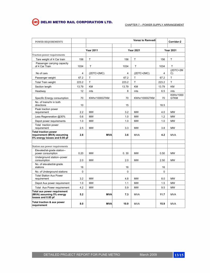
POWER REQUIREMENTS Vanaz to Ramvadi
Corridor-2
Year 2011 Year 2021 Year 2031
Traction power requirements
Tare weight of 4 Car train 156 T 156 T 156 T
Passenger carrying capacity of 4 Car Train 1034 T 1034 T 1034 T
No of cars 4 (2DTC+2MC) 4 (2DTC+2MC) 4 (2DTC+2MC)
Passenger weight 67.2 T 67.2 T 67.2 T
Total Train weight 223.2 T 223.2 T 223.2 T
Section length 13.79 KM 13.79 KM 13.79 KM
Headway 12 mts 8 mts 6.5 mts
Specific Energy consumption 70 KWhr/1000GTKM 70 KWhr/1000GTKM 70 KWhr/1000GTKM
No. of trains/hr in both directions 10 15 18.5
Peak traction power requirement 2.2 MW 3.2 MW 4.0 MW
Less Regeneration @30% 0.6 MW 1.0 MW 1.2 MW
Depot power requirements 1.0 MW 1.0 MW 1.0 MW
Total traction power requirement 2.5 MW 3.3 MW 3.8 MW
Total traction power requirement (MVA) assuming 5% energy losses and 0.95 pf
2.8 MVA 3.6 MVA 4.2 MVA
Station aux power requirements
Elevated/at-grade station--power consumption 0.20 MW 0. 30 MW 0.50 MW
Underground station--power consumption 2.0 MW 2.0 MW 2.50 MW
No. of elevated/at-grade stations 16 16 16
No. of Underground stations 0 0 0
Total Station Aux Power requirement 3.2 MW 4.8 MW 8.0 MW
Depot Aux power requirement 1.0 MW 1.1 MW 1.5 MW
Total Aux Power requirement 4.2 MW 5.9 MW 9.5 MW
Total aux power requirement (MVA) assuming 5% energy losses and 0.85 pf
5.2 MVA 7.3 MVA 11.7 MVA
Total traction & aux power requirement
8.0 MVA 10.9 MVA 15.9 MVA
CHAPTER 7 – POWER SUPPLY ARRANGEMENT
14/15
DETAILED PROJECT REPORT FOR PUNE METRO March 2009
ANNEXURE 7.3
CHAPTER 7 – POWER SUPPLY ARRANGEMENT
15/15
DETAILED PROJECT REPORT FOR PUNE METRO March 2009