chapter 7: electricity 7: electricity • all ... •electricity is a form of energy produced by...
TRANSCRIPT


CHAPTER 7: ELECTRICITY • All matters are made of small particles called atoms.
• Protons have positive electric charged and electrons have negative electric charged.
• static electricity – phenomena where charges that are not moving. PMR 09
• Objects can lose or gain electrons by rubbing with different types of objects
• If a neutral object loses electrons, it becomes positively charged.
• If a neutral object gains electrons, it becomes negatively charged

Electrostatic charge Electroscope is a device that is used to detect and identify the presence of static electric charges
Using an electroscope to identify static electric charges in an object:
i.The presence of charge in an object can be determined by observing any deflection on the gold leaves.
When the electroscope is not charged, the gold leaves hang straight down. When the electroscope is charged, the gold leaves deflect from its normal

Observation
Material Observation
Bits of paper ____________ the plastic ruler
Water stream ____________ the plastic ruler
Electroscope The gold leaf _________

Observation
Material Observation
Bits of paper Attracted towards the plastic ruler
Water stream Attracted towards the plastic ruler
Electroscope The gold leaf diverged

PENANG 12
The comb become charged
Water stream will deflect further
The comb become more charged

Static electrical charges

Observation
• Polythene-polythene
• Strips _____ each other
• _________ force
• Polythene-cellulose acetate
• Strips ______ each other
• _________ force
repel
attract
Repulsive
Attractive

electroscope

Electrostatic charge – Van Dee Graf
Electron flow Electron flow

PENANG 12
Positive charge
The pointer of Galvanometer deflects
- Electric current is produced - electron flow
Sparks are produced
Electrons transfer/jump off from the finger To the metal dome.

Here is a bigger Van de Graaff
generator

An even bigger one!

A giant Van de Graaff generator

The biggest--25 Million Volts Oak Ridge National Lab in Tennessee

Van de Graaff generator
Dome
Wire
Gas pipe
Galvanometer

Van De Graff
Spark produces when electron jumping from the small dome into bigger Dome and touch molecul of air.

Van de Graaff generator • Sparks are produced
• The galvanometer pointer deflects (Ammeter boleh pakai juga, tapi mesti Van dee Graff yang besar)

• Voltage – voltmeter – volt – to measure voltage
• Current – ammeter – ampere – to measure current flow
• Electron flow – galvanometer – to detect electron flow

Everyday phenomena caused by static electrical charges.
• 1. LIGHTNING • Lightning is produced by a
discharge of electrical charges from one cloud to another or between a cloud and the Earth.
• Negative static electrical charged build up on the cloud during a storm as strong wind rubs against water particles in the clouds/air. The negative charges leap to the ground or another cloud causing lightning as shown below.

Everyday phenomena caused by static electrical charges.
• 2. PETROL TANKER
• On hot days, a moving petrol tanker becomes charged due to friction with the surrounding air. A metal chain is connected from the petrol tank to the ground so that static electrical charges can be transferred from the petrol tank to the ground and prevent explosion.

Everyday phenomena caused by static electrical charges.
• 3. TYRES OF AEROPLANE
• Due to friction, aeroplanes become charged when flying in the air. Thus, when landing, there is a strip of metal conductor sliding against the ground to discharge the aeroplane.

Everyday phenomena caused by static electrical charges.
• 4. SPARK PLUG
• When a car engine is ignited, there is transfer of charges in the spark plugs that produces sparks and subsequently burns the fuel.

ELECTRICITY • Electricity is a form of energy produced by electric
current.
• Electricity is used in many ways, such as lightning up a bulb, heating a kettle or spinning a ceiling fan.
• Electricity can be obtained from various sources. Examples of sources of electrical energy are; – 1. simple cell
– 2. dry cell
– 3. wet cell (acid-lead accumulator)
– 4. mercury cell and lithium cell

VOLTAGE & CURRENT • current is the rate of flow of charges (or electrons) through a
conducting medium such as metal. Current increases when more electrons are flowing through a conductor.
• The flowing of electrons through a conductor is driven by voltages, produced by batteries or generators.
• Voltage is the difference in potential energy that causes electrons to flow from an area with more electrons to an area with fewer, producing an electric current


Measurement of I, and V

CURRENT FLOW & ELECTRON FLOW
The direction of current and electron
flow in an electric circuit.
• according to the conventional current flow, current flows from the positive terminal to the negative terminal as shown in figure 7.9 below
• However according to the electron flow, electron flows from negative terminal to the positive terminal.

How you should be thinking about electric circuits:
Voltage: a force that
pushes the current
through the circuit (in
this picture it would be
equivalent to gravity)

Resistance: friction that
impedes flow of current
through the circuit
(rocks in the river)
How you should be thinking about electric circuits:

Current: the actual
“substance” that is
flowing through the
wires of the circuit
(electrons!)
How you should be thinking about electric circuits:

RESISTANCE • electric current loses energy as it moves through a
conductor because the particles in the conductor resist the flow of electrons.
• Resistance is the property of a material that opposes the flow of current (electrons) through it.
• When resistance increases, the current flow in a material decreases and vise versa. (CONTROL)
• Resistor is a substance that opposes the flow of electric charge in order to control the flow of electric current. Examples; rheostats, fixed resistors and bulbs.

Resistance

Resistance
• ability opposes the flow of electrons
• High resistance allows only a small current
• Is measured in Ohms (Ω)
V
A Bright
+
+
–
–

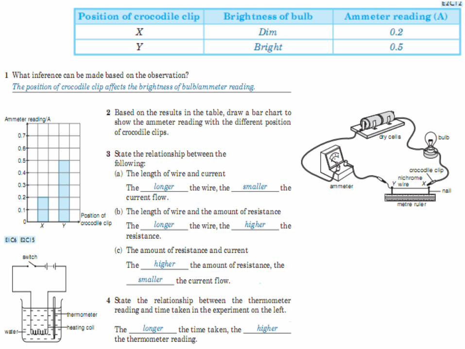
Resistance depend on • Length of conductor
• Longer conductor, higher resistance
• Diameter/thickness of conductor
• Bigger diameter, lower resistance
• Type of conductor
• Copper & aluminium has low resistance

Measurement of I, and V

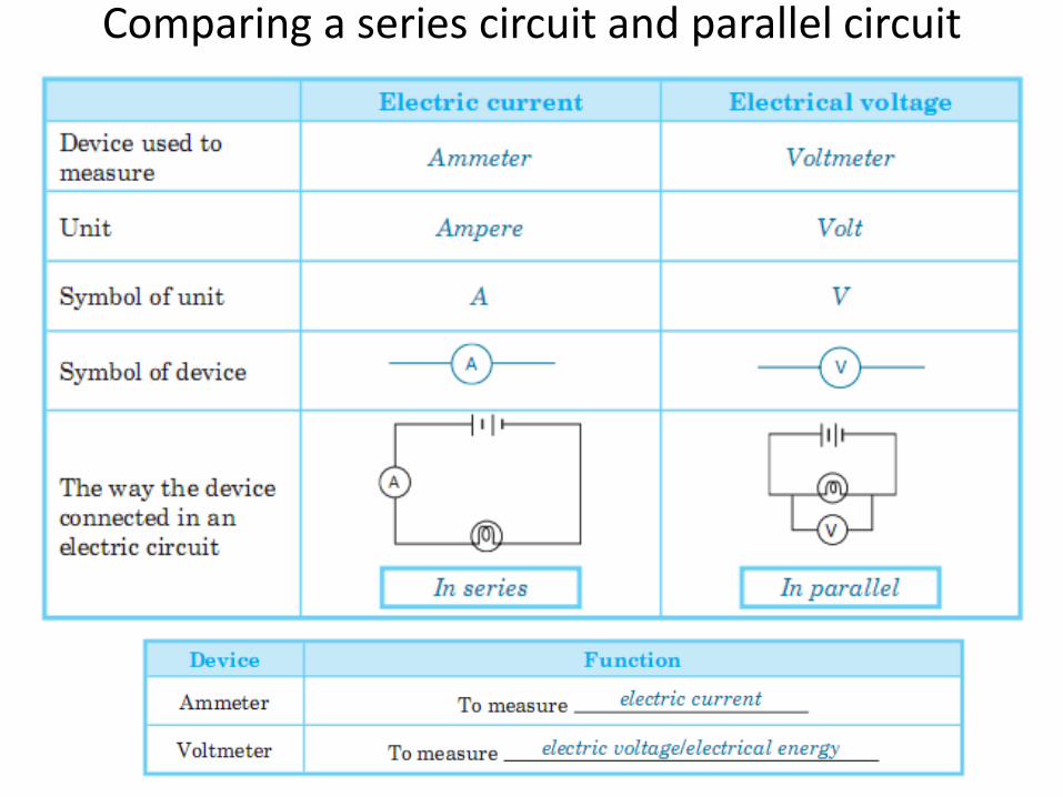
MEASURING ELECTRICITY • Electric current is measured by using an ammeter.
• Ammeter is connected in an electrical circuit in series.
• Voltage is measured by using a Voltmeter.
• Voltmeter is connected in an electrical circuit in parallel.
• The symbol of current is I and its SI unit is the ampere (A).
• The symbol of voltage is V and its SI unit is the Volt (V).
• The symbol of resistance is R and its SI unit is the Ohm (Ω ).
Experiment page 132 & Science Process Skill page 99-100

Ammeter
• Device measure electric current
• In unit amperes (A)
• Connect in series
A
A Bright
+
–

Voltmeter
• Device measure voltage
• In unit volts (V)
• Connect in parallel
V
Bright
V
+ –

measuring current


Would This Work?

Circuit Diagram 1. Closed circuit - electric current can flow
from one end of dry cell to the other and the bulb will light up.
2. Open Circuit - Electric current cannot
flow in the circuit and the bulb will not light up.
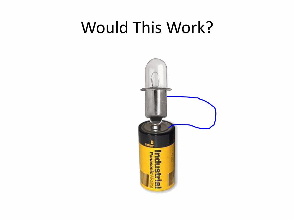
Would This Work?

Would This Work?

The Central Concept: Closed Circuit

PMR 07

Simple Circuits • Series circuit
– All in a row
– 1 path for electricity
– 1 light goes out and the circuit is broken
• Parallel circuit – Many paths for electricity
– 1 light goes out and the others stay on

Drawing of complete circuit

Complete circuit

Series vs Parallel

Series circuit

Series circuit

Parallel circuit

Parallel circuit


The circuit is no longer complete, therefore current can not flow
The voltage decreases because the current is decreased and the resistance increases.

The current remains the same. The total resistance drops in a parallel circuit as more bulbs are added
The current increases.


Series circuit Parallel circuit
voltage
current
Resistance


Comparing a series circuit and parallel circuit
A B
Comparing a series circuit and parallel circuit

Relationship between voltage, current and resistance


R =
V =
I =
V __
I
OHM’S LAW

Ohm’s Law
I = V / R
Georg Simon Ohm (1787-1854)
I = Current (Amperes) (amps) V = Voltage (Volts) R = Resistance (ohms)

Test

PMR 09


THINK ABOUT THIS?
SBP 11


• Mana nyala lebih terang?
• Apa jadi bila satu mentol terbakar?

• Mana nyala lebih terang?
• Apa jadi bila satu mentol terbakar?

• Mana nyala lebih terang?
• Apa jadi bila satu mentol terbakar?
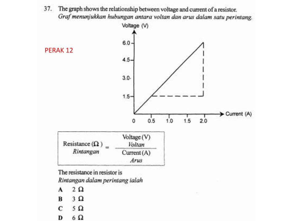
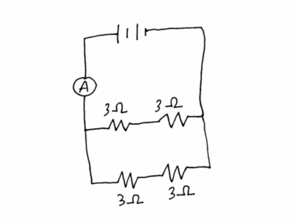
PERAK 12


Electric current component and symbol

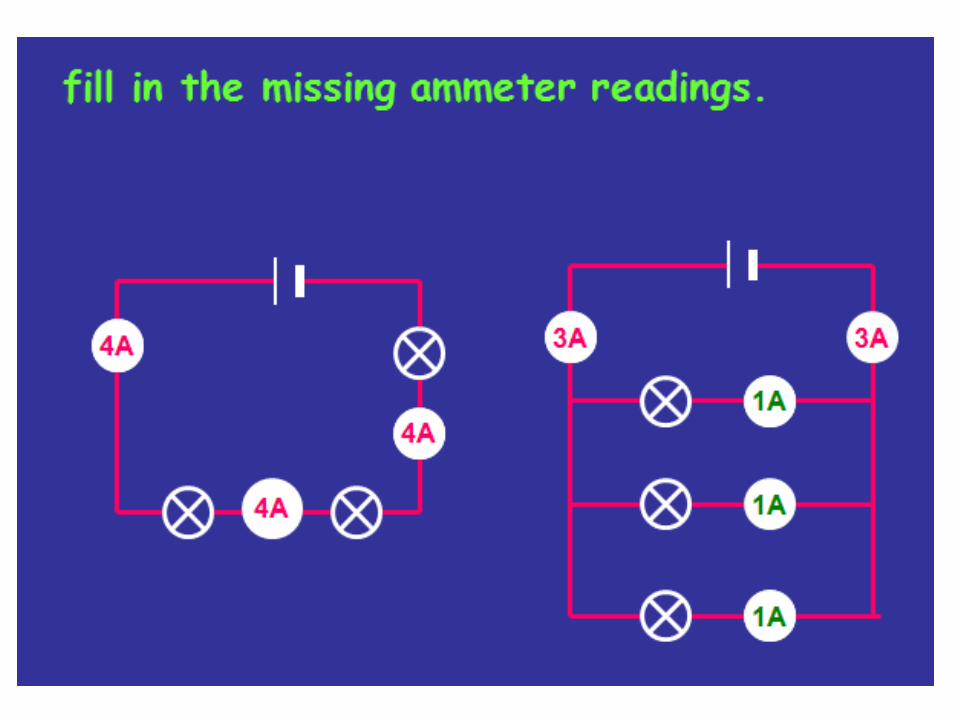
Current, voltage and resistance in a series circuit/parallel

PMR 2011

PMR 2012

MAGNETISM • A magnetic field is the area around a magnet where
magnetic effects or magnetic forces can be felt. • • Magnetic fields are represented by the magnetic lines of
forces. • The direction of the magnetic field can be seen by
plotting using a compass. • The magnetic field or the lines that represent magnetic
force do not meet each other and are closest together near the poles.
• The lines of magnetic force begin from the north pole and end at the south pole.
• This is because the magnetic field is the strongest near the poles. Away from the poles, the lines are further apart as the field is weaker.
• The direction of the magnetic field can be detected by using a compass.
• A freely suspended magnet will eventually stop in a north-south direction. This principal is used in a compass.


Magnetic field
• Field of force that exists around a magnet
Magnetic field lines

Magnetic Field

Magnetic Field

Draw the magnetic field
• Pattern formed by iron filing

Direction of the magnetic field
• Point from the North pole to the South pole

Magnetic field strength
• Closer together – strong
• Far apart – weak
• Strongest at the two poles
Strong Magnetic field
Weak Magnetic field

Magnet used in a compass
• Always point to the Magnetic North
• This property used in compass
Magnetised needle

Test yourself (draw)

Solution

ELECTROMAGNETISM. • A current flowing through a straight conductor produces
a magnetic field around the conductor. • The magnetic field produced around a straight conductor
is circular in shape. • An electromagnet is a conductor that has the same
properties as a magnet. • When current flows around a piece of iron, the iron
becomes a magnet. However, its magnetism disappears when the current stops flowing.
• The strength of the magnetic field of an electromagnet can be increased by.
– Increasing the number of coils in a solenoid. • Solenoid is an electrical conductor wound into a
cylindrical coil. When current flows through a solenoid, the magnetic field pattern formed resembles the magnetic field pattern of a permanent bar magnet.
– Increasing the current that flows through the solenoid.
– Reducing the diameter of a solenoid. – Iron core – magnetic field is stronger if a soft iron
core (pure iron) is placed inside the solenoid.

Learning Outcomes:
• relate the current flow through a conductor to magnetism
• describe what an electromagnet is

Current carrying conductor

Current carrying conductor
• When current flow through straight conductor, it becomes magnetised
• Magnetic field lines form concentric circles around it

Right Hand Grip Rule

PMR 2012

Electromagnet
• Conductor which becomes magnetised when electric current flows through it
• Is a temporary magnet

ELECTROMAGNETISM. • The poles of solenoid can be
identified in the following ways: – The pattern of the current can be
seen from the ends. When a solenoid is viewed from its end, the pattern of current seen represents the pole of the end.
• – Left hand grip rule: When the
hand is held as shown in figure below, the direction of the thumb represents the direction of the north pole while the direction of the other fingers represents the direction of the current.

Magnetic field strength
• Closer together – strong
• Far apart – weak
• Strongest at the two poles
Strong Magnetic field
Weak Magnetic field

Direction of the magnetic field
• Point from the North pole to the South pole


PMR 09

SOLENOID PMR 05

COMPARE
B

PMR 2005
PMR 08

PMR 2005

PMR 2005 … sambungan


PMR 2012

PMR 2012

PMR 2012


1.Power Hydro station

2.Step-up transformer

3.Switch zone

4. National Grid System

5. Step-Down transformer

6. Consumer
houses
Light industry
Heavy industry

SUPER TEST


Penutup
2. Tasbih Kifarah.
1. Baca Surah Al-`Ashr