chapter 7: deck wearing surface
TRANSCRIPT

Drafting and Design Presentation Standards Volume 3: Structural Drafting Standards Chapter 7: Deck Wearing Surface October 2016

Drafting and Design Presentation Standards Manual, Transport and Main Roads, October 2016
Copyright
http://creativecommons.org/licenses/by/3.0/au/
© State of Queensland (Department of Transport and Main Roads) 2016
Feedback: Please send your feedback regarding this document to: [email protected]
Volume 3: Structural Drafting Standards – Chapter 7: Deck Wearing Surface
Drafting and Design Presentation Standards Manual, Transport and Main Roads, October 2016 i
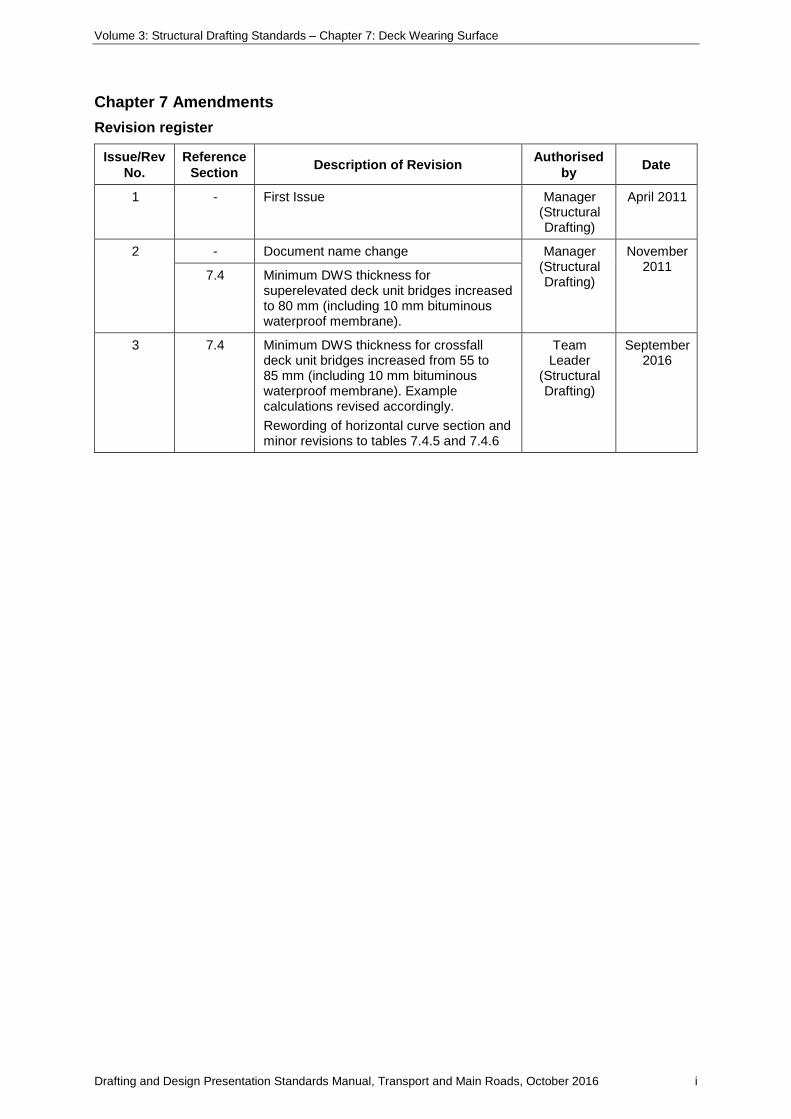
Chapter 7 Amendments Revision register
Issue/Rev No.
Reference Section Description of Revision Authorised
by Date
1 - First Issue Manager (Structural Drafting)
April 2011
2 - Document name change Manager (Structural Drafting)
November 2011 7.4 Minimum DWS thickness for
superelevated deck unit bridges increased to 80 mm (including 10 mm bituminous waterproof membrane).
3 7.4 Minimum DWS thickness for crossfall deck unit bridges increased from 55 to 85 mm (including 10 mm bituminous waterproof membrane). Example calculations revised accordingly. Rewording of horizontal curve section and minor revisions to tables 7.4.5 and 7.4.6
Team Leader
(Structural Drafting)
September 2016
Volume 3: Structural Drafting Standards – Chapter 7: Deck Wearing Surface
Drafting and Design Presentation Standards Manual, Transport and Main Roads, October 2016 ii
Contents
7 Deck Wearing Surface ...................................................................................................................1
7.1 Glossary of terms ............................................................................................................................ 1
7.2 Figures and examples shown in this volume .................................................................................. 1
7.3 General ........................................................................................................................................... 1
7.4 Thickness of DWS on PSC deck units ........................................................................................... 2
7.5 DWS on RC decks .......................................................................................................................... 8
7.6 DWS on footways/bikeways ........................................................................................................... 8
7.7 Mass of DWS .................................................................................................................................. 9
Table 7.4-5 - Fall Values (in mm’s) with 3% Superelevation ....................................................................6
Table 7.4-6 - Fall Values (in mm’s) with 6% Superelevation ....................................................................7
Figure 7.4-1- Decks with Crossfall (Crowned) ..........................................................................................2
Figure 7.4-2 - Decks with Constant Crossfall/Superelevation ..................................................................3
Figure 7.4-3 - Deck Wearing Surface Profiles (Crown) ............................................................................4
Figure 7.4-4 - Offset Allowance ................................................................................................................5
Figure 7.4-7 - Alignment of Units ..............................................................................................................8
Figure 7.6-1 - Examples of DWS on Footways/Bikeways ........................................................................9
Figure 7.7-1 - Corrector Course and Surfacing Layer ..............................................................................9
Figure 7.7-2 - Mass of DWS for deck units ........................................................................................... 10
Volume 3: Structural Drafting Standards – Chapter 7: Deck Wearing Surface
Drafting and Design Presentation Standards Manual, Transport and Main Roads, October 2016 1
7 Deck Wearing Surface
7.1 Glossary of terms
For a complete glossary of terms refer Chapter 1 Introduction.
7.2 Figures and examples shown in this volume
The figures and examples shown in this volume are for presentation purposes only, and may contain some details that are now superseded. These details have been included for ease of reference, to illustrate typical solutions, and to show the required standard of drafting presentation. The details are not to be used without an engineering check and certification by a Structural RPEQ to confirm that the details are appropriate for the specific project.
7.3 General
This chapter is to be read in conjunction with MRTS84 Deck Wearing Surface and MRTS84A Cold Milling Bridge Deck Wearing Surface.
On bridges the most common use for Deck Wearing Surface (DWS) is on PSC deck unit bridges. The deck units hog during curing and the amount of hog varies over time, culminating in the design hog at 100 days after casting. This design hog at 100 days is used in calculating the depth of DWS. These design hogs, in reality, vary significantly and an uneven deck surface is formed. DWS is used to eliminate these variances and to provide an even running surface.
DWS on bridges is comprised of a tack coat, bituminous waterproof membrane, and a surfacing layer. Sometimes a corrector course is laid between the bituminous waterproof membrane and the surfacing layer. The corrector course is used to take out most of the variances due to the hogs of the units and construction of the bridge. This provides a more even surface for the final surfacing layer.
DWS can also be used on an RC deck, however, most of the variances are taken out by the final concrete deck surface. In this case there is usually only a final surfacing layer applied to the deck surface to produce an even running surface. This chapter will mainly concentrate on the first type of bridge deck, DWS on deck units.
The thickness of DWS on a structure should be kept to a minimum to reduce the dead load on the bridge, but it shall be thick enough to account for the effect of the hog, crossfall of the pavement each way from the bridge centreline (if appropriate) and any minor alignment variations over the length of the bridge.
To prevent aquaplaning, the minimum crossfall or superelevation of the running surface is 2.5%. Historically only 1.5% was required. While the mass of DWS has now increased significantly, creating a larger dead load, the deck units are able to accept this increased load and the larger crossfall or superelevation enhances the drainage aspects of the structure. For further information refer Chapter 10 - Bridge Geometry, Section 10.8 - Vertical Alignment – Transverse Alignment.
Dense graded asphalt DG10 is the preferred road corrector course layer. The corrector coarse sits above a 10 mm nominal thick layer of bituminous waterproof membrane.
Dense graded asphalt DG14 is the preferred road surfacing layer. The layer is 45 mm thick for transversely stressed deck unit bridges and 50 mm thick for bridges with a RC deck. Refer MRTS30 Asphalt Pavements, Table 12.2.6.5 for thickness limits and Chapter 5 -Notes, Section 5.6 - General Arrangement Notes for additional details.

Volume 3: Structural Drafting Standards – Chapter 7: Deck Wearing Surface
Drafting and Design Presentation Standards Manual, Transport and Main Roads, October 2016 2
7.4 Thickness of DWS on PSC deck units
Deck wearing surface profiles generally fall into two categories, decks with crossfall (crowned) and decks with constant crossfall (or superelevation).
Decks with Crossfall (Crowned pavement). Refer Figure 7.4-1 - Decks with Crossfall (Crowned).
Crossfall is 2.5% minimum each way from bridge centreline. This may not be possible however when widening existing bridges. The design of these bridges will need to deal with the specific site conditions. Refer Chapter 10 – Bridge Geometry.
The minimum thickness of DWS at any point is 85 mm consisting of bituminous waterproof membrane and 75 mm thick asphalt. For calculation purposes, the thickness of bituminous waterproof membrane is 10 mm and is not included when calculating DWS quantities. The thickness of DWS varies along the length of the span due to the hog of the deck units, with the minimum thickness occurring at midspan. Refer Figure 7.7-2 - Mass of DWS for Deck Units.
At abutments and piers, the nominal DWS thickness at the centreline of roadway is calculated as follows:
• width between kerbs (mm) / 2 x crossfall (%) + design hog (mm) at 100 days + 85 mm, for example:
− width between kerbs = 9220 mm. Crossfall = 3% Design hog at 100 days = 35 mm The thickness of DWS at the centreline of abutments and piers will be:
9220 / 2 x 0.03 + 35 + 85 = 258 mm (round up to 260 mm).
Figure 7.4-1- Decks with Crossfall (Crowned)
Decks with Constant Crossfall or Superelevation. Refer Figure 7.4-2 - Decks with Constant Crossfall/Superelevation.
The DWS is a nominally constant thickness across the width of the deck. The minimum thickness of DWS at any point is 85 mm consisting of 10 mm bituminous waterproof membrane and 75 mm asphalt.
The thickness of DWS varies along the length of the span due to the hog of the deck units, with the minimum thickness occurring at midspan.

Volume 3: Structural Drafting Standards – Chapter 7: Deck Wearing Surface
Drafting and Design Presentation Standards Manual, Transport and Main Roads, October 2016 3
At abutments and piers, the nominal DWS thickness is calculated as follows:
• design hog (mm) at 100 days + 85 mm, for example:
− superelevation = 5% (however this has no effect on the DWS thickness) Design hog at 100 days = 35 mm
− the thickness of DWS at the centreline of abutments and piers will be:
35 + 85 = 115 mm.
Figure 7.4-2 - Decks with Constant Crossfall/Superelevation
Vertical Curves (VC)
Vertical curves are not true circles, rather they are parabolic curves. The following formula may be used to calculate the vertical off set (V) on a vertical curve. Note that because the curve is parabolic, the formula is not completely accurate, however it is usually accurate enough for the purpose of calculating vertical offsets.
Consider the following example:
A bridge with a crowned deck is on a crest VC producing a vertical offset of 20 mm per span. This gives an extra 20 mm of DWS thickness from the deck unit at the centre of the span to the running surface. The designers can then reduce the thickness of DWS required at the abutments and piers by

Volume 3: Structural Drafting Standards – Chapter 7: Deck Wearing Surface
Drafting and Design Presentation Standards Manual, Transport and Main Roads, October 2016 4
20 mm and still maintain the minimum 85 mm thickness (75 mm DWS and 10 mm waterproof membrane) at the centre of the span. Refer to Figure 7.4-3 - Deck Wearing Surface Profiles (Crown) and the accompanying calculations.
Figure 7.4-3 - Deck Wearing Surface Profiles (Crown)
Note: Dimensions shown in the diagram are examples only
Thickness of DWS at kerb at abutments and piers (crowned pavement).
For Hog VC: A = 50 hog + 85 minimum – 20 offset = 115 mm.
For constant grade B = 50 hog + 85 minimum = 135 mm.
For Sag VC: C = 50 hog + 85 minimum + 20 offset = 155 mm.
In cases where the offset due to the crest VC is greater than the hog of the deck unit, the minimum 85 mm applies at the abutment and pier kerbs.
The DWS thickness on the kerb line at the centre of the span will therefore be 85 mm minimum
+ offset due to VC.
Volume 3: Structural Drafting Standards – Chapter 7: Deck Wearing Surface
Drafting and Design Presentation Standards Manual, Transport and Main Roads, October 2016 5
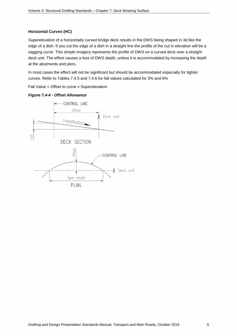
Horizontal Curves (HC)
Superelevation of a horizontally curved bridge deck results in the DWS being shaped in 3d like the edge of a dish. If you cut the edge of a dish in a straight line the profile of the cut in elevation will be a sagging curve. This simple imagery represents the profile of DWS on a curved deck over a straight deck unit. The effect causes a loss of DWS depth, unless it is accommodated by increasing the depth at the abutments and piers.
In most cases the effect will not be significant but should be accommodated especially for tighter curves. Refer to Tables 7.4.5 and 7.4.6 for fall values calculated for 3% and 6%
Fall Value = Offset to curve x Superelevation
Figure 7.4-4 - Offset Allowance
Volume 3: Structural Drafting Standards – Chapter 7: Deck Wearing Surface
Drafting and Design Presentation Standards Manual, Transport and Main Roads, October 2016 6
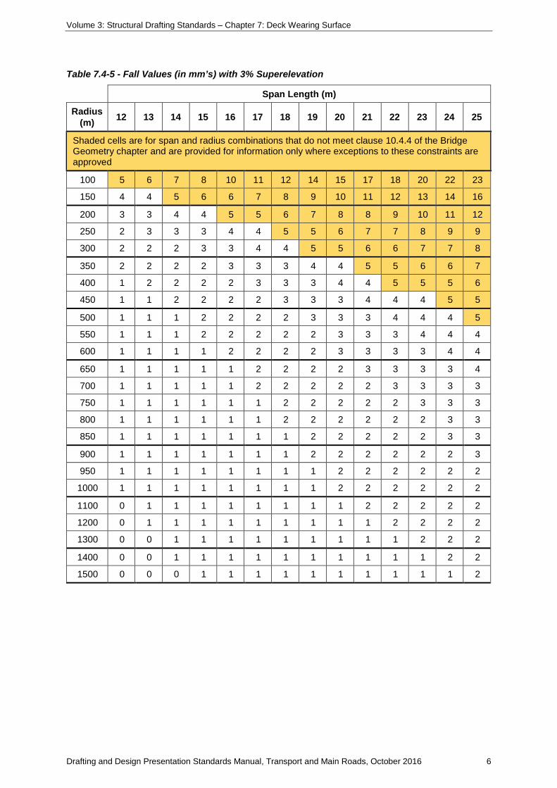
Table 7.4-5 - Fall Values (in mm’s) with 3% Superelevation
Span Length (m)
Radius (m) 12 13 14 15 16 17 18 19 20 21 22 23 24 25
Shaded cells are for span and radius combinations that do not meet clause 10.4.4 of the Bridge Geometry chapter and are provided for information only where exceptions to these constraints are approved
100 5 6 7 8 10 11 12 14 15 17 18 20 22 23
150 4 4 5 6 6 7 8 9 10 11 12 13 14 16
200 3 3 4 4 5 5 6 7 8 8 9 10 11 12
250 2 3 3 3 4 4 5 5 6 7 7 8 9 9
300 2 2 2 3 3 4 4 5 5 6 6 7 7 8
350 2 2 2 2 3 3 3 4 4 5 5 6 6 7
400 1 2 2 2 2 3 3 3 4 4 5 5 5 6
450 1 1 2 2 2 2 3 3 3 4 4 4 5 5
500 1 1 1 2 2 2 2 3 3 3 4 4 4 5
550 1 1 1 2 2 2 2 2 3 3 3 4 4 4
600 1 1 1 1 2 2 2 2 3 3 3 3 4 4
650 1 1 1 1 1 2 2 2 2 3 3 3 3 4
700 1 1 1 1 1 2 2 2 2 2 3 3 3 3
750 1 1 1 1 1 1 2 2 2 2 2 3 3 3
800 1 1 1 1 1 1 2 2 2 2 2 2 3 3
850 1 1 1 1 1 1 1 2 2 2 2 2 3 3
900 1 1 1 1 1 1 1 2 2 2 2 2 2 3
950 1 1 1 1 1 1 1 1 2 2 2 2 2 2
1000 1 1 1 1 1 1 1 1 2 2 2 2 2 2
1100 0 1 1 1 1 1 1 1 1 2 2 2 2 2
1200 0 1 1 1 1 1 1 1 1 1 2 2 2 2
1300 0 0 1 1 1 1 1 1 1 1 1 2 2 2
1400 0 0 1 1 1 1 1 1 1 1 1 1 2 2
1500 0 0 0 1 1 1 1 1 1 1 1 1 1 2

Volume 3: Structural Drafting Standards – Chapter 7: Deck Wearing Surface
Drafting and Design Presentation Standards Manual, Transport and Main Roads, October 2016 7
Table 7.4-6 - Fall Values (in mm’s) with 6% Superelevation
Span Length (m)
Radius (m) 12 13 14 15 16 17 18 19 20 21 22 23 24 25
Shaded cells are for span and radius combinations that do not meet clause 10.4.4 of the Bridge Geometry chapter and are provided for information only where exceptions to these constraints are approved
100 11 13 15 17 19 22 24 27 30 33 36 40 43 47
150 7 8 10 11 13 14 16 18 20 22 24 26 29 31
200 5 6 7 8 10 11 12 14 15 17 18 20 22 23
250 4 5 6 7 8 9 10 11 12 13 15 16 17 19
300 4 4 5 6 6 7 8 9 10 11 12 13 14 16
350 3 4 4 5 5 6 7 8 9 9 10 11 12 13
400 3 3 4 4 5 5 6 7 8 8 9 10 11 12
450 2 3 3 4 4 5 5 6 7 7 8 9 10 10
500 2 3 3 3 4 4 5 5 6 7 7 8 9 9
550 2 2 3 3 3 4 4 5 5 6 7 7 8 9
600 2 2 2 3 3 4 4 5 5 6 6 7 7 8
650 2 2 2 3 3 3 4 4 5 5 6 6 7 7
700 2 2 2 2 3 3 3 4 4 5 5 6 6 7
750 1 2 2 2 3 3 3 4 4 4 5 5 6 6
800 1 2 2 2 2 3 3 3 4 4 5 5 5 6
850 1 1 2 2 2 3 3 3 4 4 4 5 5 6
900 1 1 2 2 2 2 3 3 3 4 4 4 5 5
950 1 1 2 2 2 2 3 3 3 3 4 4 5 5
1000 1 1 1 2 2 2 2 3 3 3 4 4 4 5
1100 1 1 1 2 2 2 2 2 3 3 3 4 4 4
1200 1 1 1 1 2 2 2 2 3 3 3 3 4 4
1300 1 1 1 1 1 2 2 2 2 3 3 3 3 4
1400 1 1 1 1 1 2 2 2 2 2 3 3 3 3
1500 1 1 1 1 1 1 2 2 2 2 2 3 3 3
Volume 3: Structural Drafting Standards – Chapter 7: Deck Wearing Surface
Drafting and Design Presentation Standards Manual, Transport and Main Roads, October 2016 8
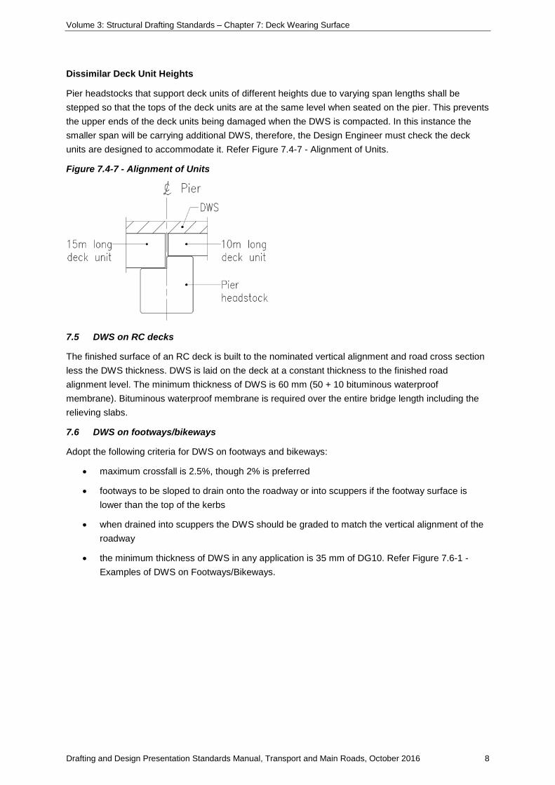
Dissimilar Deck Unit Heights
Pier headstocks that support deck units of different heights due to varying span lengths shall be stepped so that the tops of the deck units are at the same level when seated on the pier. This prevents the upper ends of the deck units being damaged when the DWS is compacted. In this instance the smaller span will be carrying additional DWS, therefore, the Design Engineer must check the deck units are designed to accommodate it. Refer Figure 7.4-7 - Alignment of Units.
Figure 7.4-7 - Alignment of Units
7.5 DWS on RC decks
The finished surface of an RC deck is built to the nominated vertical alignment and road cross section less the DWS thickness. DWS is laid on the deck at a constant thickness to the finished road alignment level. The minimum thickness of DWS is 60 mm (50 + 10 bituminous waterproof membrane). Bituminous waterproof membrane is required over the entire bridge length including the relieving slabs.
7.6 DWS on footways/bikeways
Adopt the following criteria for DWS on footways and bikeways:
• maximum crossfall is 2.5%, though 2% is preferred
• footways to be sloped to drain onto the roadway or into scuppers if the footway surface is lower than the top of the kerbs
• when drained into scuppers the DWS should be graded to match the vertical alignment of the roadway
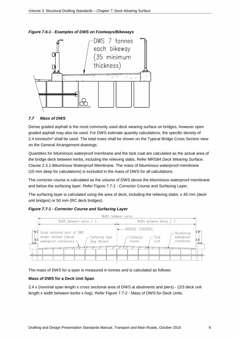
• the minimum thickness of DWS in any application is 35 mm of DG10. Refer Figure 7.6-1 - Examples of DWS on Footways/Bikeways.
Volume 3: Structural Drafting Standards – Chapter 7: Deck Wearing Surface
Drafting and Design Presentation Standards Manual, Transport and Main Roads, October 2016 9
Figure 7.6-1 - Examples of DWS on Footways/Bikeways
7.7 Mass of DWS
Dense graded asphalt is the most commonly used deck wearing surface on bridges, however open graded asphalt may also be used. For DWS estimate quantity calculations, the specific density of 2.4 tonnes/m3 shall be used. The total mass shall be shown on the Typical Bridge Cross Section view on the General Arrangement drawings.
Quantities for bituminous waterproof membrane and the tack coat are calculated as the actual area of the bridge deck between kerbs, including the relieving slabs. Refer MRS84 Deck Wearing Surface, Clause 2.3.1-Bituminous Waterproof Membrane. The mass of bituminous waterproof membrane (10 mm deep for calculations) is excluded in the mass of DWS for all calculations.
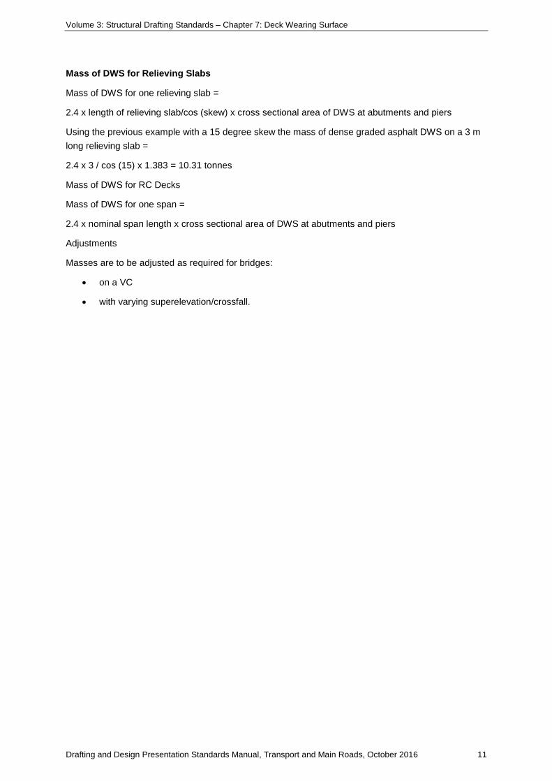
The corrector course is calculated as the volume of DWS above the bituminous waterproof membrane and below the surfacing layer. Refer Figure 7.7-1 - Corrector Course and Surfacing Layer.
The surfacing layer is calculated using the area of deck, including the relieving slabs, x 45 mm (deck unit bridges) or 50 mm (RC deck bridges).
Figure 7.7-1 - Corrector Course and Surfacing Layer
The mass of DWS for a span is measured in tonnes and is calculated as follows:
Mass of DWS for a Deck Unit Span
2.4 x (nominal span length x cross sectional area of DWS at abutments and piers) - (2/3 deck unit length x width between kerbs x hog). Refer Figure 7.7-2 - Mass of DWS for Deck Units.

Volume 3: Structural Drafting Standards – Chapter 7: Deck Wearing Surface
Drafting and Design Presentation Standards Manual, Transport and Main Roads, October 2016 10
Refer the following example:
Span Length (nominal) = 14 m
Minimum depth of DWS at kerbs (not including membrane) = 0.045 m
Design hog at 100 days = 0.035 m
Depth of DWS only (excluding 10 mm of bituminous waterproof membrane) at kerbs at abutments and piers = 0.045 + 0.035 = 0.08 m
Width between kerbs = 9.22 m Crossfall = 3%
Depth of DWS at centreline at abutments and piers (rounded up to nearest 5 mm)
= 9.22 / 2 x 3% + 0.08 = 0.22 m
Cross sectional area of DWS at abuts and piers = 9.22 x 0.08 + 9.22 / 2 x 0.14
= 1.383 m2
Mass of DWS for one span =
2.4 x (14 x 1.383 – 2/3 x 13.95 x 9.22 x 0.035) = 39.266 tonnes
Mass of Surfacing Layer =
2.4 x (14 x 9.22 x 0.045) = 13.941 tonnes
Round up to nearest 0.1 tonne = 14.0 tonnes
Mass of Corrector Course = 39.266 – 14
= 25.266 tonnes
Round up to nearest 0.1 tonne = 25.3 tonnes.
Figure 7.7-2 - Mass of DWS for deck units
Volume 3: Structural Drafting Standards – Chapter 7: Deck Wearing Surface
Drafting and Design Presentation Standards Manual, Transport and Main Roads, October 2016 11
Mass of DWS for Relieving Slabs
Mass of DWS for one relieving slab =
2.4 x length of relieving slab/cos (skew) x cross sectional area of DWS at abutments and piers
Using the previous example with a 15 degree skew the mass of dense graded asphalt DWS on a 3 m long relieving slab =
2.4 x 3 / cos (15) x 1.383 = 10.31 tonnes
Mass of DWS for RC Decks
Mass of DWS for one span =
2.4 x nominal span length x cross sectional area of DWS at abutments and piers
Adjustments
Masses are to be adjusted as required for bridges:
• on a VC
• with varying superelevation/crossfall.
