chapter 6.8 requirements for the construction, equipment ... · chapter 6.8 requirements for the...
TRANSCRIPT

6.8-1
Chapter 6.8
Requirements for the construction, equipment, type approval, inspections and tests, and marking of tank-wagons, demountable tanks and tank-containers and tank swap bodies, with shells made of metallic materials, and battery-wagons and multiple element gas containers (MEGCs)
NOTE: For portable tanks and UN multiple-element gas containers (MEGCs) see Chapter 6.7, for fibre-reinforced plastics tank-containers see Chapter 6.9, for vacuum-operated waste tanks see Chap-ter 6.10.
6.8.1 Scope
6.8.1.1 The requirements across the whole width of the page apply both to tank-wagons, to demountable tanks and battery-wagons, and to tank-containers, tank swap bodies and MEGCs. Those contained in a single column apply only: – to tank-wagons, demountable tanks and battery-wagons (left hand column); – to tank-containers, tank swap bodies and MEGCs (right hand column).
6.8.1.2 These requirements shall apply to tank-wagons, demountable tanks and battery-
wagons tank-containers, tank swap bodies and MEGCs
used for the carriage of gaseous, liquid, powdery or granular substances.
6.8.1.3 Section 6.8.2 sets out the requirements applicable to tank-wagons, to demountable tanks, tank-containers, tank swap bodies intended for the carriage of substances of all classes and battery-wagons and MEGCs for gases of Class 2. Sections 6.8.3 to 6.8.5 contain special requirements supplementing or modifying the requirements of section 6.8.2.
6.8.1.4 For provisions concerning use of these tanks, see Chapter 4.3.
6.8.2 Requirements applicable to all classes
6.8.2.1 Construction
Basic principles
6.8.2.1.1 Shells, their service and structural equipment shall be designed to withstand without loss of contents (other than quantities of gas escaping through any degassing vents): – static and dynamic stresses in normal conditions of carriage as defined in 6.8.2.1.2 and 6.8.2.1.13; – prescribed minimum stresses as defined in 6.8.2.1.15.
6.8.2.1.2 Tank-wagons shall be constructed as to be capable of withstanding, under the maximum permissible load, the stresses which occur during carriage by rail. As regards these stresses, reference should be made to the tests prescribed by the competent authority.1
Tank-containers and their fastenings shall, under the maximum permissible load be capable of ab-sorbing the forces equal to those exerted by: – in the direction of travel: twice the total mass; – horizontally at right angles to the direction of
travel: the total mass; (where the direction of travel is not clearly determined, twice the total mass in each direction);
– vertically upwards: the total mass; – vertically downwards: twice the total mass.
6.8.2.1.3 The walls of the shells shall have at least the thickness specified in 6.8.2.1.17 and 6.8.2.1.18. 6.8.2.1.17 to 6.8.2.1.20.
6.8.2.1.4 Shells shall be designed and constructed in accordance with the requirements of standards listed in 6.8.2.6 or of a technical code recognized by the competent authority, in accordance with 6.8.2.7, in which the material is chosen and the shell thickness determined taking into account maximum and minimum
1 These requirements shall be deemed to be met if the competent body in accordance with the technical specification for interoperability (TSI) relating to the subsystem "rolling stock – freight wagons" of the trans-European conventional rail system (Commission decision 2006/861/EC of 28 July 2006, pub-lished in the Official Journal of the European Union L 344, 8 December 2006) has carried out this as-sessment in the framework of the EC conformity assessment of the wagon.

6.8-2
filling and working temperatures, but the following minimum requirements of 6.8.2.1.6 to 6.8.2.1.26 shall be met.
6.8.2.1.5 Tanks intended to contain certain dangerous substances shall be provided with additional protection. This may take the form of additional thickness of the shell (increased calculation pressure) determined in the light of the dangers inherent in the substances concerned or of a protective device (see the special provisions of 6.8.4).
6.8.2.1.6 Welds shall be skilfully made and shall afford the fullest safety. The execution and checking of welds shall comply with the requirements of 6.8.2.1.23.
6.8.2.1.7 Measures shall be taken to protect shells against the risk of deformation as a result of a negative internal pressure.
Shells, other than shells according to 6.8.2.2.6, designed to be equipped with vacuum valves shall be able to withstand, without permanent deformation, an external pressure of not less than 21 kPa (0.21 bar) above the internal pressure. Shells used for the carriage of solid substances (powdery or granular) of packing groups II or III only, which do not liquefy during carriage, may be designed for a lower external pressure but not less than 5 kPa (0.05 bar). The vacuum valves shall be set to relieve at a vacuum set-ting not greater than the tank's design vacuum pressure. Shells, which are not designed to be equipped with a vacuum valve shall be able to withstand, without permanent deformation an external pressure of not less than 40 kPa (0.4 bar) above the internal pressure.
Materials for shells
6.8.2.1.8 Shells shall be made of suitable metallic materials which, unless other temperature ranges are pre-scribed in the various classes, shall be resistant to brittle fracture and to stress corrosion cracking be-tween –20 °C and +50 °C.
6.8.2.1.9 The materials of shells or of their protective linings which are in contact with the contents shall not con-tain substances liable to react dangerously (see "Dangerous reaction" in 1.2.1) with the contents, to form dangerous compounds, or substantially to weaken the material.
If contact between the substance carried and the material used for the construction of the shell entails a progressive decrease in the shell thickness, this thickness shall be increased at manufacture by an ap-propriate amount. This additional thickness to allow for corrosion shall not be taken into consideration in calculating the shell thickness.
6.8.2.1.10 For welded shells only materials of faultless weldability whose adequate impact strength at an ambient temperature of –20 °C can be guaranteed, particularly in the weld seams and the zones adjacent thereto, shall be used.
Water-quenched steel may not be used for welded steel shells. If fine-grained steel is used, the guaran-teed value of the yield strength Re shall not exceed 460 N/mm2 and the guaranteed value of the upper limit of tensile strength Rm shall not exceed 725 N/mm2, in accordance with the specifications of the ma-terial.
6.8.2.1.11 Ratios of Re/Rm exceeding 0.85 are not allowed for steels used in the construction of welded tanks. Re = apparent yield strength for steels having a clearly-defined yield point or
guaranteed 0.2% proof strength for steels with no clearly-defined yield point (1% for austenitic steels)
Rm = tensile strength.
The values specified in the inspection certificate for the material shall be taken as a basis in determining this ratio in each case.
6.8.2.1.12 For steel, the elongation at fracture, in % shall be not less than
2N/mm in stenght tensile determined000 10 but in any case for fine-grained steels it shall be not less than
16 % and not less than 20 % for other steels.
For aluminium alloys the elongation at fracture shall be not less than 12%2.
2 In the case of sheet metal the axis of the tensile test-piece shall be at right angles to the direction of rolling. The permanent elongation at fracture shall be measured on test-pieces of circular cross-section in which the gauge length l is equal to five times the diameter d (l = 5d); if test-pieces of rectangular section are used, the gauge length shall be calculated by the formula

6.8-3
Calculation of the shell thickness
6.8.2.1.13 The pressure on which the shell thickness is based shall not be less than the calculation pressure, but the stresses referred to in 6.8.2.1.1 shall also be taken into account, and, if necessary, the following stresses:
In the case of wagons in which the tank constitutes a stressed self-supporting member, the shell shall be designed to withstand the stresses thus im-posed in addition to stresses from other sources.
Under each of these stresses the safety factors to be observed shall be the following: – for metals having a clearly-defined yield point: a
safety factor of 1.5 in relation to the apparent yield strength; or
– for metals with no clearly-defined yield point: a safety factor of 1.5 in relation to the guaranteed 0.2% proof strength (1% maximum elongation for austenitic steels).
6.8.2.1.14 The calculation pressure is in the second part of the code (see 4.3.4.1) according to Column (12) of Ta-ble A of Chapter 3.2.
When "G" appears, the following requirements shall apply: (a) Gravity-discharge shells intended for the carriage of substances having a vapour pressure not ex-
ceeding 110 kPa (1.1 bar) (absolute pressure) at 50 °C shall be designed for a calculation pressure of twice the static pressure of the substance to be carried but not less than twice the static pressure of water.
(b) Pressure-filled or pressure-discharge shells intended for the carriage of substances having a vapour pressure not exceeding 110 kPa (1.1 bar) (absolute pressure) at 50 °C shall be designed for a calcu-lation pressure equal to 1.3 times the filling or discharge pressure.
When the numerical value of the minimum calculation pressure is given (gauge pressure) the shell shall be designed for this pressure which shall not be less than 1.3 times the filling or discharge pressure. The following minimum requirements shall apply in these cases: (c) Shells intended for the carriage of substances having a vapour pressure of more than 110 kPa
(1.1 bar) at 50 °C and a boiling point of more than 35 °C shall, whatever their filling or discharge sys-tem, be designed for a calculation pressure of not less than 150 kPa (1.5 bar) gauge pressure or 1.3 times the filling or discharge pressure, whichever is the higher.
(d) Shells intended for the carriage of substances having a boiling point of not more than 35 °C shall, whatever their filling or discharge system, be designed for a calculation pressure equal to 1.3 times the filling or discharge pressure but not less than 0.4 MPa (4 bar) (gauge pressure).
6.8.2.1.15 At the test pressure, the stress σ at the most severely stressed point of the shell shall not exceed the material-dependent limits prescribed below. Allowance shall be made for any weakening due to the welds.
6.8.2.1.16 For all metals and alloys, the stress σ at the test pressure shall be lower than the smaller of the values given by the following formulae:
σ ≤ 0.75 Re or σ ≤ 0.5 Rm
where Re = apparent yield strength for steels having a clearly-defined yield point or
0,2%-Dehngrenze für Stähle ohne ausgeprägter Streckgrenze (1%-Dehngrenze für austenitische Stähle)
Rm = tensile strength.
The values of Re and Rm to be used shall be specified minimum values according to material standards. If no material standard exists for the metal or alloy in question, the values of Re and Rm used shall be approved by the competent authority or by a body designated by that authority.
When austenitic steels are used, the specified minimum values according to the material standards may be exceeded by up to 15% if these higher values are attested in the inspection certificate. The minimum
l = 5.65 F0
where F0 indicates the initial cross-section area of the test-piece.

6.8-4
values shall, however, not be exceeded when the formula given in 6.8.2.1.18 is applied.
Minimum shell thickness
6.8.2.1.17 The shell thickness shall not be less than the greater of the values determined by the following formulae:
e = λσ 2D PT
e = σ 2D PC
where: e = minimum shell thickness in mm PT = test pressure in MPa PC = calculation pressure in MPa as specified in 6.8.2.1.14 D = internal diameter of shell in mm σ = permissible stress, as defined in 6.8.2.1.16, in N/mm2 λ = a coefficient not exceeding 1, allowing for any weakening due to welds, and linked to the inspection
methods defined in 6.8.2.1.23.
The thickness shall in no case be less than that defined in 6.8.2.1.18. 6.8.2.1.18 to 6.8.2.1.20.
6.8.2.1.18 Shells shall be not less than 6 mm thick if of mild steel3, or of equivalent thickness if of another metal. For powdery or granular substances, this thickness may be reduced to 5 mm for mild steel or to an equivalent thickness for other metals.
Whichever metal is used, the minimum wall thick-ness of the shell shall in no case be less than 4.5 mm.
Shells shall be not less than 5 mm thick if of mild steel3 (in conformity with the requirements of 6.8.2.1.11 and 6.8.2.1.12) or of equivalent thick-ness if of another metal.
Where the diameter is more than 1.80 m4, this thickness shall be increased to 6 mm except in the case of tanks intended for the carriage of powdery or granular substances, if the shell is of mild steel3 or to an equivalent thickness if of another metal.
Whatever the metal used, the shell thickness shall in no case be less than 3 mm.
"Equivalent thickness" means the thickness obtained by the following formula5:
( )3 211
01
ARm
e464e =
3 For the definitions of "mild steel" and "reference steel" see 1.2.1. "Mild steel" in this case also covers a steel referred to in EN material standards as "mild steel", with a minimum tensile strength between 360 N/mm2 and 490 N/mm2 and a minimum elongation at fracture conforming to 6.8.2.1.12.
4 For shells not of a circular cross-section, for example box-shaped or elliptical shells, the indicated di-ameters shall correspond to those calculated on the basis of a circular cross-section of the same area. For such shapes of cross-section the radius of convexity of the shell wall shall not exceed 2 000 mm at the sides or 3 000 mm at the top and bottom.
5 This formula is derived from the general formula:
3
2
11
0001 ARm
ARmee ⎟⎟
⎠
⎞⎜⎜⎝
⎛=
where
e1 = minimum shell thickness for the metal chosen, in mm;
e0 = minimum shell thickness for mild steel, in mm, according to 6.8.2.1.18 and 6.8.2.1.19;
Rm0 = 370 (tensile strength for reference steel, see definition 1.2.1, in N/mm2);
A0 = 27 (elongation at fracture for reference steel, in %);

6.8-5
6.8.2.1.19 (Reserved) Where protection of the tank against damage is provided according to 6.8.2.1.20, the competent authority may allow the aforesaid minimum thick-nesses to be reduced in proportion to the protec-tion provided; however, the said thicknesses shall be not less than 3 mm in the case of mild steel3, or than an equivalent thickness in the case of other materials, for shells not more than 1.80 m4 in di-ameter. For shells of a diameter exceeding 1.80 m4
this minimum thickness shall be increased to 4 mm in the case of mild steel3, and to an equivalent thickness in the case of other metals.
Equivalent thickness means the thickness given by the formula in 6.8.2.1.18.
The thickness of shells with protection against damage in accordance with 6.8.2.1.20 shall not be less than the values given in the table below:
Diameter of shell ≤ 1.80 m
> 1.80 m
Stainless austenitic steels
2.5 mm 3 mm
Other steels 3 mm 4 mm
Aluminium alloys 4 mm 5 mm
Min
imum
thic
knes
s of
she
lls
Pure aluminium of 99.80%
6 mm 8 mm
6.8.2.1.20 (Reserved) The protection referred to in 6.8.2.1.19 may consist of: – overall external structural protection as in
"sandwich" construction where the sheathing is secured to the shell; or
– a structure in which the shell is supported by a complete skeleton including longitudinal and transverse structural members; or
– double-wall construction.
Where the tanks are made with double walls, the space between being evacuated of air, the aggre-gate thickness of the outer metal wall and the shell wall shall correspond to the minimum wall thick-ness prescribed in 6.8.2.1.18, the thickness of the wall of the shell itself being not less than the mini-mum thickness prescribed in 6.8.2.1.19.
Where tanks are made with double walls with an intermediate layer of solid materials at least 50 mm thick, the outer wall shall have a thickness of not less than 0.5 mm if it is made of mild steel3 or at least 2 mm if it is made of a plastics material rein-forced with glass fibre. Solid foam with an impact absorption capacity such as that, for example, of polyurethane foam, may be used as the intermedi-ate layer of solid material.
6.8.2.1.21 (Reserved)
6.8.2.1.22 (Reserved)
Rm1 = minimum tensile strength of the metal chosen, in N/mm2; and
A1 = minimum elongation at fracture of the metal chosen under tensile stress, in %.

6.8-6
Welding and inspection of welds
6.8.2.1.23 The manufacturer's qualification for performing welding operations shall be one recognized by the com-petent authority. Welding shall be performed by skilled welders using a welding process whose effective-ness (including any heat treatments required) has been demonstrated by test. Non-destructive tests shall be carried out by radiography or by ultrasound and must confirm that the quality of the welding is appro-priate to the stresses.
The following checks shall be carried out in accordance with the value of the coefficient λ used in deter-mining the thickness of the shell in 6.8.2.1.17: λ = 0.8: the weld beads shall so far as possible be inspected visually on both faces and shall be sub-
jected to a non-destructive spot check. All weld "Tee" junctions with the total length of weld ex-amined to be not less than 10% of the sum of the length of all longitudinal, circumferential and radial (in the tank ends) welds shall be tested;
λ = 0.9: all longitudinal beads throughout their length, all connections, 25% of circular beads, and welds for the assembly of large-diameter items of equipment shall be subjected to non-destructive checks. Beads shall be checked visually on both sides as far as possible;
λ = 1: all beads shall be subjected to non-destructive checks and are so far as possible inspected visually on both sides. A weld test-piece shall be taken.
Where the competent authority has doubts regarding the quality of weld beads, it may require additional checks.
Other construction requirements
6.8.2.1.24 The protective lining shall be so designed that its leakproofness remains intact, whatever the deformation liable to occur in normal conditions of carriage (see 6.8.2.1.2).
6.8.2.1.25 The thermal insulation shall be so designed as not to hinder access to, or the operation of, filling and discharge devices and safety valves.
6.8.2.1.26 If shells intended for the carriage of flammable liquids having a flash-point of not more than 60 °C are fitted with non-metallic protective linings (inner layers), the shells and the protective linings shall be so designed that no danger of ignition from electrostatic charges can occur.
6.8.2.1.27 All parts of tank-wagons intended for the carriage of liquids having a flash-point of not more than 60 °C and for the carriage of flammable gases, or of UN No. 1361 carbon or UN No. 1361 carbon black, Packing Group II, shall be linked to the chassis by means of electrical connection and shall be capable of being electrically earthed. Any metal contact capable of causing electrochemical corro-sion shall be avoided.
All parts of a tank-container intended for the car-riage of liquids having a flash-point of not more than 60 °C, flammable gases, or UN No. 1361 car-bon or UN No. 1361 carbon black, packing group II, shall be capable of being electrically earthed. Any metal contact capable of causing electrochemical corrosion shall be avoided.
6.8.2.1.28 (Reserved)
6.8.2.1.29 The minimum distance between the headstock plane and the most protruding point at the shell extremity on tank-wagons shall be 300 mm.
Alternatively for tank-wagons for substances other than those for which the requirements of special provision TE 25 of 6.8.4 (b) apply, buffer override protection of a design approved by the competent authority shall be provided. This alternative is only applicable to tank-wagons used solely on railway infrastructure requiring a freight vehicle gauge smaller than G16.
(Reserved)
6 The G1 gauge is referenced in the technical specification for interoperability (TSI) relating to the sub-system "rolling stock – freight wagons" of the trans-European conventional rail system (Commission decision 2006/861/EC of 28 July 2006, published in the Official Journal of the European Union L 344, 8 December 2006).

6.8-7
6.8.2.2 Items of equipment
6.8.2.2.1 Suitable non-metallic materials may be used to manufacture service and structural equipment.
The attachments of equipment which is welded on shall be made in such a way that the shell is pre-vented from being ruptured as a result of stresses caused by an accident. These requirements shall be deemed to be met if point 1.1.10 of UIC leaflet 5737 (Technical conditions for the construction of tank-wagons) is applied.
The items of equipment shall be so arranged as to be protected against the risk of being wrenched off or damaged during carriage or handling. They shall exhibit a suitable degree of safety comparable to that of the shells themselves, and shall in particular: – be compatible with the substances carried; and – meet the requirements of 6.8.2.1.1.
Piping shall be designed, constructed and installed so as to avoid the risk of damage due to thermal ex-pansion and contraction, mechanical shock and vibration.
The leakproofness of the service equipment shall be ensured even in the event of the overturning of the tank-wagon or tank-container.
The gaskets shall be made of a material compatible with the substance carried and shall be replaced as soon as their effectiveness is impaired, for example as a result of ageing.
Gaskets ensuring the leakproofness of fittings requiring manipulation during normal use of tanks shall be so designed and arranged that manipulation of the fittings incorporating them does not damage them.
6.8.2.2.2 Each bottom-filling or bottom-discharge opening in tanks which are referred to, in Column (12) of Table A of Chapter 3.2, with a tank code including the letter "A" in its third part (see 4.3.4.1.1) shall be equipped with at least two mutually independent closures, mounted in series, comprising – an external stop-valve with piping made of a malleable metal material and – a closing device at the end of each pipe which may be a screw-threaded plug, a blank flange or an
equivalent device. This closing device shall be sufficiently tight so that the substance is contained without loss. Measures shall be taken to enable the safe release of pressure in the discharge pipe be-fore the closing device is completely removed.
Each bottom-filling or bottom-discharge opening in tanks which are referred to, in Column (12) of Table A of Chapter 3.2, with a tank code including the letter "B" in its third part (see 4.3.3.1.1 or 4.3.4.1.1) shall be equipped with at least three mutually independent closures, mounted in series, comprising – an internal stop-valve, i.e. a stop-valve mounted inside the shell or in a welded flange or companion
flange; – an external stop-valve or an equivalent device8,
one at the end of each pipe and as near as possible to the shell and
– a closing device at the end of each pipe which may be a screw-threaded plug, a blank flange or an equivalent device. This closing device shall be sufficiently tight so that the substance is contained without loss. Measures shall be taken to enable the safe release of pressure in the discharge pipe be-fore the closing device is completely removed.
However, in the case of tanks intended for the carriage of certain crystallizable or highly viscous sub-stances and shells fitted with an ebonite or thermoplastic coating, the internal stop-valve may be re-placed by an external stop-valve provided with additional protection.
The internal stop-valve shall be operable either from above or from below. Its setting – open or closed – shall so far as possible in each case be capable of being verified from the ground. Internal stop-valve control devices shall be so designed as to prevent any unintended opening through impact or an inadver-tent act.
The internal shut-off device shall continue to be effective in the event of damage to the external control device.
7 7th edition of the UIC leaflet applicable from 1 October 2008.
8 In the case of tank-containers of less than 1 m3 capacity, the external stop-valve or other equivalent device may be replaced by a blank flange.

6.8-8
In order to avoid any loss of contents in the event of damage to the external fittings (pipes, lateral shut-off devices), the internal stop-valve and its seating shall be protected against the danger of being wrenched off by external stresses or shall be so designed as to resist them. The filling and discharge devices (in-cluding flanges or threaded plugs) and protective caps (if any) shall be capable of being secured against any unintended opening.
The position and/or direction of closure of shut-off devices shall be clearly apparent.
All openings of tanks which are referred to in Column (12) of Table A of Chapter 3.2, by a tank code in-cluding letter "C" or "D" in its third part (see 4.3.3.1.1 and 4.3.4.1.1) shall be situated above the surface level of the liquid. These tanks shall have no pipes or pipe connections below the surface level of the liquid. The cleaning openings (fist-holes) are, however, permitted in the lower part of the shell for tanks referred to by a tank code including letter "C" in its third part. This opening shall be capable of being sealed by a flange so closed as to be leakproof and whose design shall be approved by the competent authority or by a body designated by that authority.
6.8.2.2.3 Tanks that are not hermetically closed may be fitted with vacuum valves or with self-operating ventilation valves to avoid an unacceptable negative internal pressure; these valves shall be set to relieve at a vacuum
setting not greater than the vacuum pressure for which the tank has been designed (see 6.8.2.1.7). Her-metically closed tanks shall not be fitted with vacuum valves
or with self-operating ventilation valves. However, tanks of the tank code SGAH, S4AH or L4BH, fitted with these valves which open at a negative
pressure of not less than 21 kPa (0.21 bar) shall be considered as being hermetically closed. For tanks intended for the carriage of solid substances (powdery or granular) of packing group II or III only, which do not liquefy during transport, the negative pressure may be reduced to not less than 5 kPa (0.05 bar).
Vacuum valves and self-operating ventilation valves and venting systems (see 6.8.2.2.6) used on tanks intended for the carriage of substances meeting the
flash-point criteria of Class 3, shall prevent the immediate passage of flame into the tank by means of a suitable device to prevent the propagation of a flame, or the shell of the tank shall be capable of with-standing, without leakage, an explosion resulting from the passage of the flame.
If the protection consists of a suitable flame trap or flame arrester, it shall be positioned as close as pos-sible to the shell or the shell compartment. For multi-compartment tanks, each compartment shall be protected separately.
For tanks with self-operating ventilation valves, the connection between the self-operating ventilation valve and the bottom valve shall be so arranged that the valves do not open in the event of defor-mation of the tank or the contents cannot escape in the event of their opening.
6.8.2.2.4 The shell or each of its compartments shall be provided with an opening large enough to permit inspec-tion.
These openings shall be provided with closures designed for a test pressure of at least 0.4 MPa (4 bar). Hinged dome covers for tanks with a test pressure of more than 0.6 MPa (6 bar) shall not be permitted.
6.8.2.2.5 (Reserved)
6.8.2.2.6 Tanks intended for the carriage of liquids having a vapour pressure of not more than 110 kPa (1.1 bar) (absolute) at 50 °C shall have a venting system and a safety device to prevent the contents from spilling out if the tank overturns; otherwise they shall conform to 6.8.2.2.7 or 6.8.2.2.8.
6.8.2.2.7 Tanks intended for the carriage of liquids having a vapour pressure of more than 110 kPa (1.1 bar) at 50 °C and a boiling point of more than 35 °C shall have a safety valve set at not less than 150 kPa (1.5 bar) (gauge pressure) and which shall be fully open at a pressure not exceeding the test pressure; otherwise they shall conform to 6.8.2.2.8.

6.8-9
6.8.2.2.8 Tanks intended for the carriage of liquids having a boiling point of not more than 35 °C shall have a safety valve set at not less than 300 kPa (3 bar) gauge pressure and which shall be fully open at a pres-sure not exceeding the test pressure; otherwise they shall be hermetically closed9.
6.8.2.2.9 Movable parts such as covers, closures, etc., which are liable to come into frictional or percussive con-tact with aluminium shells intended for the carriage of flammable liquids having a flash-point of not more than 60 °C or for the carriage of flammable gases shall not be made of unprotected corrodible steel.
6.8.2.2.10 If tanks required to be hermetically closed are equipped with safety valves, these shall be preceded by a bursting disc, and the following conditions shall be observed:
The arrangement of the bursting disc and the safety valve shall be such as to satisfy the competent au-thority. A pressure gauge or another suitable indicator shall be provided in the space between the burst-ing disc and the safety valve, to enable detection of any rupture, perforation or leakage of the disc which may disrupt the action of the safety valve.
6.8.2.3 Type approval
6.8.2.3.1 The competent authority or a body designated by that authority shall issue in respect of each new type of tank-wagon, demountable tank, tank-container, tank swap body, battery-wagon or MEGC a certificate attesting that the type, including fastenings, which it has inspected is suitable for the purpose for which it is intended and meets the construction requirements of 6.8.2.1, the equipment requirements of 6.8.2.2 and the special conditions for the classes of substances carried.
The certificate shall show: – the results of the test; – an approval number for the type;
The approval number shall consist of the distin-guishing sign10 of the State in whose territory the approval was granted and a registration number.
– the tank code in accordance with 4.3.3.1.1 or 4.3.4.1.1; – the alphanumeric codes of special provisions of construction (TC), equipment (TE) and type approval
(TA) of 6.8.4 which are shown in column (13) of Table A of Chapter 3.2 for those substances for the carriage of which the tank has been approved;
– if required, the substances and/or group of substances for the carriage of which the tank has been approved. These shall be shown with their chemical name or the corresponding collective entry (see 2.1.1.2), to-gether with their classification (class, classification code and packing group). With the exception of substances of Class 2 and those listed in 4.3.4.1.3, the listing of approved sub-stances may be dispensed with. In such cases, groups of substances permitted on the basis of the tank code shown in the rationalised approach in 4.3.4.1.2 shall be accepted for carriage taking into account any relevant special provision.
The substances referred to in the certificate or the groups of substances approved according to the ra-tionalised approach shall, in general, be compatible with the characteristics of the tank. A reservation shall be included in the certificate if it was not possible to investigate this compatibility exhaustively when the type approval was issued.
A copy of the certificate shall be attached to the tank record of each tank, battery-wagon or MEGC con-structed (see 4.3.2.1.7).
6.8.2.3.2 If the tanks, battery-wagons or MECGs are manufactured in series without modification this approval shall be valid for the tanks, battery-wagons or MECGs manufactured in series or according to the proto-type.
A type approval may however serve for the approval of tanks with limited variations of the design that either reduce the loads and stresses on the tanks (e.g. reduced pressure, reduced mass, reduced vol-ume) or increase the safety of the structure (e.g. increased shell thickness, more surge-plates, de-creased diameter of openings). The limited variations shall be clearly described in the type approval cer-tificate.
9 For the definition of "hermetically closed tank" see 1.2.1.
10 Distinguishing sign for use in international traffic prescribed by the Convention on Road Traffic (Vienna, 1968).

6.8-10
6.8.2.3.3 The following requirements apply to tanks for which special provision TA 4 of 6.8.4 (and therefore 1.8.7.2.4) does not apply.
The type approval shall be valid for a maximum of ten years. If within that period the relevant technical requirements of RID (including referenced standards) have changed so that the approved type is no longer in conformity with them, the competent authority or the body designated by that authority which issued the type approval shall withdraw it and inform the holder of the type approval.
NOTE: For the ultimate dates for withdrawal of existing type approvals, see column (5) of the tables in 6.8.2.6 or 6.8.3.6 as appropriate.
If a type approval has expired or has been withdrawn, the manufacture of the tanks, battery-wagons or MEGCs according to that type approval is no longer authorised.
In such a case, the relevant provisions concerning the use, periodic inspection and intermediate inspec-tion of tanks, battery-wagons or MEGCs contained in the type approval which has expired or has been withdrawn shall continue to apply to these tanks, battery-wagons or MEGCs constructed before the ex-piry or the withdrawal if they may continue to be used.
They may continue to be used as long as they remain in conformity with the requirements of RID. If they are no longer in conformity with the requirements of RID they may continue to be used only if such use is permitted by relevant transitional measures in Chapter 1.6.
Type approvals may be renewed by a complete review and assessment for conformity with the provi-sions of RID applicable at the date of renewal. Renewal is not permitted after a type approval has been withdrawn. Interim amendments of an existing type approval not affecting conformity (see 6.8.2.3.2) do not extend or modify the original validity of the certificate.
NOTE: The review and assessment of conformity can be done by a body other than the one which is-sued the original type approval.
The issuing body shall keep all documents for the type approval for the whole period of validity including its renewals if granted.
If the designation of the issuing body is revoked or restricted, or when the body has ceased activity, the competent authority shall take appropriate steps to ensure that the files are either processed by another body or kept available.
6.8.2.4 Inspections and tests
6.8.2.4.1 Shells and their equipment shall either together or separately undergo an initial inspection before being put into service. This inspection shall include: – a check of conformity to the approved type; – a check of the design characteristics11, – an examination of the internal and external conditions; – a hydraulic pressure test12 at the test pressure indicated on the plate prescribed in 6.8.2.5.1; and – a leakproofness test and a check of satisfactory operation of the equipment.
Except in the case of Class 2, the test pressure for the hydraulic pressure test depends on the calcula-tion pressure and shall be at least equal to the pressure indicated below:
Calculation pressure (bar) Test pressure (bar) G13 G13 1.5 1.5 2.65 2.65 4 4 10 4
11 The check of the design characteristics shall also include, for shells requiring a test pressure of 1 MPa (10 bar) or higher, the taking of weld test-pieces (work samples) in accordance with 6.8.2.1.23 and the tests prescribed in 6.8.5.
12 In special cases and with the agreement of the expert approved by the competent authority, the hy-draulic pressure test may be replaced by a pressure test using another liquid or gas, where such an operation does not present any danger.
13 G = minimum calculation pressure according to the general requirements of 6.8.2.1.14 (see 4.3.4.1).

6.8-11
15 4 21 10 (414)
The minimum test pressures for Class 2 are given in the table of gases and gas mixtures in 4.3.3.2.5.
The hydraulic pressure test shall be carried out on the shell as a whole and separately on each com-partment of compartmented shells.
The hydraulic pressure test shall be carried out before the installation of a thermal insulation as may be necessary.
If the shells and their equipment are tested separately, they shall be jointly subjected to a leakproofness test after assembly in accordance with 6.8.2.4.3.
The leakproofness test shall be carried out separately on each compartment of compartmented shells.
6.8.2.4.2 Shells and their equipment shall undergo periodic inspections no later than every eight years five years.
These periodic inspections shall include: – An external and internal examination; – A leakproofness test in accordance with 6.8.2.4.3 of the shell with its equipment and check of the sat-
isfactory operation of all the equipment; – As a general rule, a hydraulic pressure test12 (for the test pressure for the shells and compartments if
applicable, see 6.8.2.4.1).
Sheathing for thermal or other insulation shall be removed only to the extent required for reliable ap-praisal of the characteristics of the shell.
In the case of tanks intended for the carriage of powdery or granular substances, and with the agreement of the expert approved by the competent authority, the periodic hydraulic pressure tests may be omitted and replaced by leakproofness tests in accordance with 6.8.2.4.3, at an effective internal pressure at least equal to the maximum working pressure.
6.8.2.4.3 Shells and their equipment shall undergo intermediate inspections at least every four years two and a half years after the initial inspection and each periodic inspection. These intermediate inspections may be per-
formed within three months before or after the specified date.
However, the intermediate inspection may be performed at any time before the specified date.
If an intermediate inspection is performed more than three months before the due date, another interme-diate inspection shall be performed at the latest
four years two and a half years
after this date.
These intermediate inspections shall include a leakproofness test of the shell with its equipment and check of the satisfactory operation of all the equipment. For this purpose the tank shall be subjected to an effective internal pressure at least equal to the maximum working pressure. For tanks intended for the carriage of liquids or solids in the granular or powdery state, when a gas is used for the leakproofness test it shall be carried out at a pressure at least equal to 25% of the maximum working pressure. In all cases, it shall not be less than 20 kPa (0.2 bar) (gauge pressure).
For tanks equipped with venting systems and a safety device to prevent the contents spilling out if the tank overturns, the pressure test shall be equal to the static pressure of the filling substance.
The leakproofness test shall be carried out separately on each compartment of compartmented shells.
6.8.2.4.4 When the safety of the tank or of its equipment may have been impaired as a result of repairs, alterations or accident, an exceptional check shall be carried out. If an exceptional check fulfilling the requirements of 6.8.2.4.2 has been performed, then the exceptional check may be considered to be a periodic inspec-tion. If an exceptional check fulfilling the requirements of 6.8.2.4.3 has been performed then the excep-tional check may be considered to be an intermediate inspection.
6.8.2.4.5 The tests, inspections and checks in accordance with 6.8.2.4.1 to 6.8.2.4.4 shall be carried out by the expert approved by the competent authority. Certificates shall be issued showing the results of these operations, even in the case of negative results. These certificates shall refer to the list of the substances
14 Minimum test pressure for UN No. 1744 bromine or UN No. 1744 bromine solution.

6.8-12
permitted for carriage in this tank or to the tank code and the alphanumeric codes of special provisions in accordance with 6.8.2.3.
A copy of these certificates shall be attached to the tank record of each tank, battery-wagon or MEGC tested (see 4.3.2.1.7).
Expert for performing tests and inspections on the tanks of tank-wagons
6.8.2.4.6 In order to be considered as an expert within the meaning of 6.8.2.4.5, one shall be approved by the competent authority and meet the following re-quirements. However, this mutual recognition shall not apply to activities in connection with an amendment of the design type approval. 1. The expert shall be independent of the parties
involved. He may neither be identical with the originator of the design, the manufacturer, the supplier, the purchaser, the owner, the holder or the user of the tanks of tank-wagons to be in-spected, nor may he be an authorized represen-tative of the aforementioned parties.
2. The expert may not engage in any activities that might conflict with his independence of judge-ment and integrity in relation to the inspection activities. The expert shall, in particular, be free from any commercial, financial or other pres-sures which might affect his judgement, particu-larly from persons or undertakings external to the inspection body with an interest in the results of the inspections carried out. The impartiality of the inspection staff shall be ensured.
3. The expert shall have at his disposal the neces-sary facilities to enable him to perform properly the technical and administrative tasks connected with the examinations and inspection operations. He shall also have access to the equipment re-quired to carry out special inspections.
4. The expert shall have appropriate qualifications, sound technical and vocational training, satisfac-tory knowledge of the provisions applicable to the inspections to be carried out and adequate practical experience of such operations. In order to ensure a high level of safety, he shall provide expertise in the field of safety of tanks of tank-wagons. He shall be capable of drawing up the necessary certificates, records and reports to demonstrate that the inspections have been car-ried out.
5. The expert shall be adequately familiar with the technology used for the construction of the tanks to be inspected, including their accessories, the use or intended use of the equipment submitted for inspection, and with the defects which may occur during use or in service.
6. The expert shall carry out the assessments and inspections with the highest degree of profes-sional reliability and technical competence. He shall ensure the confidentiality of information ob-tained in the course of the inspection activities. Proprietary rights shall be protected.
7. The amount of remuneration of the expert en-gaged in inspection activities shall not directly depend on the number of inspections carried out and in no case on the results of such inspec-tions.
8. The expert shall have adequate liability insur-ance unless, in accordance with national laws
(Reserved)

6.8-13
and regulations, the liability is assumed by the state or the undertaking of which he forms a part.
These requirements shall be met for: – the staff of a "notified body" certified in accor-
dance with Directive 1999/36/EC, – persons who are approved on the basis of an
accrediting procedure in accordance with stan-dard EN ISO/IEC 17020:2004 ("General criteria for the operation of various types of bodies per-forming inspection").
The RID Contracting States shall communicate to the secretariat of OTIF the experts who have been approved with respect to the particular inspections. The information shall include the stamp and the marking stamp. The secretariat of OTIF shall pub-lish a list of approved experts and shall ensure that this list is kept up to date.
In order to introduce and to continue to develop harmonised inspection procedures, and in order to ensure a uniform level of inspections, the secre-tariat of OTIF shall, when necessary, arrange an exchange of experiences.
6.8.2.5 Marking
6.8.2.5.1 Every tank shall be fitted with a corrosion-resistant metal plate permanently attached to the tank in a place readily accessible for inspection. The following particulars at least shall be marked on the plate by stamping or by any other similar method. These particulars may be engraved directly on the walls of the shell itself, if the walls are so reinforced that the strength of the shell is not impaired: – approval number; – manufacturer’s name or mark; – manufacturer’s serial number; – year of manufacture; – test pressure (gauge pressure)15; – external design pressure (see 6.8.2.1.7)15; – capacity of the shell15 – in the case of multiple-compartment shells, the capacity of each compart-
ment15 –, followed by the symbol "S" when the shells or the
compartments of more than 7 500 litres are divided by surge plates into sections of not more than 7 500 litres capacity;
– design temperature (only if above +50 °C or below –20 °C)15; – date and type of the most recent test: "month, year" followed by a "P" when the test is the initial test or
a periodic test in accordance with 6.8.2.4.1 and 6.8.2.4.2, or "month, year" followed by an "L" when the test is an intermediate leakproofness test in accordance with 6.8.2.4.3;
– stamp of the expert who carried out the tests; – material of the shell and reference to materials standards, if available and, where appropriate, the
protective lining.
In addition, the maximum working pressure15 allowed shall be inscribed on pressure-filled or pressure-discharge tanks.
6.8.2.5.2 The following particulars shall be inscribed on both sides of the tank-wagon itself or on a plate: – name of operator; – capacity15; – unladen mass of tank-wagon15; – load limits according to the characteristics of the
The following particulars shall be inscribed either on the tank-container itself or on a plate: – names of owner and of operator; – capacity of the shell15; – tare15; – maximum permissible laden mass15;
15 Add the units of measurement after the numerical values.
6.8-14
wagon and the nature of the lines used; – for the substances according to 4.3.4.1.3, the
proper shipping name of the substance(s) ac-cepted for carriage;
– tank code according to 4.3.4.1.1; – for substances other than those according to
4.3.4.1.3, the alphanumeric codes of all special provisions TC and TE which are shown in col-umn (13) of Table A of Chapter 3.2 for the sub-stances to be carried in the tank;
– date (month, year) of the next inspection in ac-cordance with 6.8.2.4.2 and 6.8.2.4.3 or with the TT special provisions of 6.8.4 for the sub-stance(s) accepted for carriage. If the next in-spection is an inspection in accordance with 6.8.2.4.3, the date shall be followed by the letter "L".
– for the substances according to 4.3.4.1.3, the proper shipping name of the substance(s) ac-cepted for carriage;
– tank code according to 4.3.4.1.1; – for substances other than those according to
4.3.4.1.3, the alphanumeric codes of all special provisions TC and TE which are shown in col-umn (13) of Table A of Chapter 3.2 for the sub-stances to be carried in the tank.
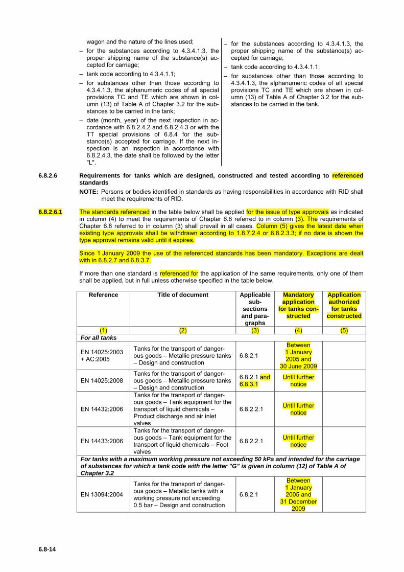
6.8.2.6 Requirements for tanks which are designed, constructed and tested according to referenced standards NOTE: Persons or bodies identified in standards as having responsibilities in accordance with RID shall
meet the requirements of RID.
6.8.2.6.1 The standards referenced in the table below shall be applied for the issue of type approvals as indicated in column (4) to meet the requirements of Chapter 6.8 referred to in column (3). The requirements of Chapter 6.8 referred to in column (3) shall prevail in all cases. Column (5) gives the latest date when existing type approvals shall be withdrawn according to 1.8.7.2.4 or 6.8.2.3.3; if no date is shown the type approval remains valid until it expires.
Since 1 January 2009 the use of the referenced standards has been mandatory. Exceptions are dealt with in 6.8.2.7 and 6.8.3.7.
If more than one standard is referenced for the application of the same requirements, only one of them shall be applied, but in full unless otherwise specified in the table below.
Reference Title of document Applicable sub-
sections and para-
graphs
Mandatory application
for tanks con-structed
Application authorized for tanks
constructed
(1) (2) (3) (4) (5) For all tanks
EN 14025:2003 + AC:2005
Tanks for the transport of danger-ous goods – Metallic pressure tanks – Design and construction
6.8.2.1
Between 1 January 2005 and
30 June 2009
EN 14025:2008
Tanks for the transport of danger-ous goods – Metallic pressure tanks – Design and construction
6.8.2.1 and 6.8.3.1
Until further notice
EN 14432:2006
Tanks for the transport of danger-ous goods – Tank equipment for the transport of liquid chemicals – Product discharge and air inlet valves
6.8.2.2.1 Until further notice
EN 14433:2006
Tanks for the transport of danger-ous goods – Tank equipment for the transport of liquid chemicals – Foot valves
6.8.2.2.1 Until further notice
For tanks with a maximum working pressure not exceeding 50 kPa and intended for the carriage of substances for which a tank code with the letter "G" is given in column (12) of Table A of Chapter 3.2
EN 13094:2004
Tanks for the transport of danger-ous goods – Metallic tanks with a working pressure not exceeding 0.5 bar – Design and construction
6.8.2.1
Between 1 January 2005 and
31 December 2009

6.8-15
Reference Title of document Applicable sub-
sections and para-
graphs
Mandatory application
for tanks con-structed
Application authorized for tanks
constructed
(1) (2) (3) (4) (5)
EN 13094:2008 + AC:2008
Tanks for the transport of danger-ous goods – Metallic tanks with a working pressure not exceeding 0.5 bar – Design and construction
6.8.2.1 Until further notice
For tanks intended for the carriage of liquid petroleum products and other dangerous sub-stances of Class 3 which have a vapour pressure not exceeding 110 kPa at 50 °C and petrol, and which have no toxic or corrosive subsidiary hazard
EN 13094:2004
Tanks for the transport of danger-ous goods – Metallic tanks with a working pressure not exceeding 0.5 bar – Design and construction
6.8.2.1
Between 1 January 2005 and
31 December 2009
EN 13094:2008 + AC:2008
Tanks for the transport of danger-ous goods – Metallic tanks with a working pressure not exceeding 0.5 bar – Design and construction
6.8.2.1 Until further notice
6.8.2.6.2 Inspection and test
The standard referenced in the table below shall be applied for the inspection and test of tanks as indi-cated in column (4) to meet the requirements of Chapter 6.8 referred to in column (3) which shall prevail in all cases.
The use of a referenced standard is mandatory.
Reference Title of document Applica-
ble sub-sections and para-
graphs
Application authorized
(1) (2) (3) (4)
EN 12972:2007 Tanks for transport of dangerous goods – Testing, in-spection and marking of metallic tanks
6.8.2.4 6.8.3.4
Until further notice
6.8.2.7 Requirements for tanks which are not designed, constructed and tested according to referenced standards
To reflect scientific and technical progress or where no standard is referenced in 6.8.2.6 or to deal with specific aspects not addressed in a standard referenced in 6.8.2.6, the competent authority may recog-nize the use of a technical code providing the same level of safety. Tanks shall, however, comply with the minimum requirements of 6.8.2.
The competent authority shall transmit to the secretariat of OTIF a list of the technical codes that it rec-ognises. The list should include the following details: name and date of the code, purpose of the code and details of where it may be obtained. The secretariat shall make this information publicly available on its website.
A standard which has been adopted for reference in a future edition of the RID may be approved by the competent authority for use without notifying the OTIF secretariat.
For testing, inspection and marking, the applicable standard as referenced in 6.8.2.6 may also be used.
6.8.3 Special requirements applicable to Class 2
6.8.3.1 Construction of shells
6.8.3.1.1 Shells intended for the carriage of compressed or liquefied gases or dissolved gases shall be made of steel.
In the case of weldless shells, by derogation from 6.8.2.1.12 a minimum elongation at fracture of 14% and also a stress σ lower than or equal to limits hereafter given according to the material may be ac-cepted: (a) When the ratio Re/Rm (of the minimum guaranteed characteristics after heat treatment) is higher
than 0.66 without exceeding 0.85: σ ≤ 0.75 Re.

6.8-16
(b) When the ratio Re/Rm (of the minimum guaranteed characteristics after heat treatment) is higher than 0.85: σ ≤ 0.5 Rm.
6.8.3.1.2 The requirements of 6.8.5 apply to the materials and construction of welded shells.
6.8.3.1.3 For double-walled shells, the wall thickness of the inner receptacle may, notwithstanding the require-ments of 6.8.2.1.18, be 3 mm if a metal is used which has good low-temperature performance cor-responding to a minimum tensile strength Rm = 490 N/mm2 and a minimum coefficient of elongation A = 30%.
If other metals are used, an equivalent minimum wall thickness shall be maintained; this thickness is to be calculated according to the formula in foot-note 5 to 6.8.2.1.18, where Rm0 = 490 N/mm2 and A0 = 30%.
The outer shell shall in this case have a minimum wall thickness of 6 mm where mild steel is con-cerned. If other materials are used, an equivalent minimum wall thickness shall be maintained, which shall be calculated according to the formula given in 6.8.2.1.18.
(Reserved)
Construction of battery-wagons and MEGCs
6.8.3.1.4 Cylinders, tubes, pressure drums and bundles of cylinders, as elements of a battery-wagon or MEGC, shall be constructed in accordance with Chapter 6.2.
NOTE 1: Bundles of cylinders which are not elements of a battery-wagon or of a MEGC shall be sub-ject to the requirements of Chapter 6.2.
2: Tanks as elements of battery-wagons and MEGCs shall be constructed in accordance with 6.8.2.1 and 6.8.3.1.
3: Demountable tanks16 are not to be considered elements of battery-vehicles or MEGCs.
6.8.3.1.5 Elements and their fastenings shall be capable of absorbing under the maximum permissible load the forces defined in 6.8.2.1.2. Under each force the stress at the most severely stressed point of the ele-ment and its fastenings shall not exceed the value defined in 6.2.5.3 for cylinders, tubes, pressure drums and bundles of cylinders and for tanks the value of σ defined in 6.8.2.1.16.
Other provisions for the construction of tank-wagons and battery-wagons
6.8.3.1.6 Tank-wagons and battery-wagons shall be fitted with buffers with a minimum energy absorption capacity of 70 kJ. This provision does not apply to tank-wagons and battery-wagons fitted with energy absorption elements in accordance with the defini-tion in 6.8.4, special provision TE 22.
(Reserved)
6.8.3.2 Items of equipment
6.8.3.2.1 The discharge pipes of tanks shall be capable of being closed by blank flanges or some other equally reliable device. For tanks intended for the carriage of refrigerated liquefied gases, these blank flanges or other equally reliable devices may be fitted with pressure-release openings of a maximum diameter of 1.5 mm.
6.8.3.2.2 Shells intended for the carriage of liquefied gases may be provided with, in addition to the openings pre-scribed in 6.8.2.2.2 and 6.8.2.2.4, openings for the fitting of gauges, thermometers, manometers and with bleed holes, as required for their operation and safety.
6.8.3.2.3 The internal stop-valve of all filling and all discharge openings of tanks with a capacity greater than 1 m3 intended for the carriage of liquefied flammable or toxic gases shall be instant-closing and shall close
16 For the definition of "demountable tank" see 1.2.1.

6.8-17
automatically in the event of an unintended movement of the tank or in the event of fire. It shall also be possible to operate the internal stop-valve by remote control.
The device which keeps the internal closure open, e.g. a rail hook, is not a component of the wagon.
6.8.3.2.4 All openings, other than those accommodating safety valves and closed bleed holes, of tanks intended for the carriage of liquefied flammable and/or toxic gases shall, if their nominal diameter is more than 1.5 mm, shall be equipped with an internal shut-off device.
6.8.3.2.5 Notwithstanding the requirements of 6.8.2.2.2, 6.8.3.2.3 and 6.8.3.2.4, tanks intended for the carriage of refrigerated liquefied gases may be equipped with external devices in place of internal devices if the ex-ternal devices afford protection against external damage at least equivalent to that afforded by the wall of the shell.
6.8.3.2.6 If the tanks are equipped with gauges in direct contact with the substance carried, the gauges shall not be made of a transparent material. If there are thermometers, they shall not project directly into the gas or liquid through the shell.
6.8.3.2.7 Filling and discharge openings situated in the upper part of tanks shall be equipped with, in addition to what is prescribed in 6.8.3.2.3, a second, external, closing device. This device shall be capable of being closed by a blank flange or some other equally reliable device.
6.8.3.2.8 Safety valves shall meet the requirements of 6.8.3.2.9 to 6.8.3.2.12 below:
6.8.3.2.9 Tanks intended for the carriage of compressed or liquefied gases or dissolved gases, may be fitted with spring-loaded safety valves. These valves shall be capable of opening automatically under a pressure between 0.9 and 1.0 times the test pressure of the tank to which they are fitted. They shall be of such a type as to resist dynamic stresses, including liquid surge. The use of dead weight or counter weight valves is prohibited. The required capacity of the safety valves shall be calculated in accordance with the formula contained in 6.7.3.8.1.1.
6.8.3.2.10 Where tanks are intended for carriage by sea, the requirements of 6.8.3.2.9 shall not prohibit the fitting of safety valves conforming to the IMDG Code.
6.8.3.2.11 Tanks intended for the carriage of refrigerated liquefied gases shall be equipped with two or more inde-pendent safety valves capable of opening at the maximum working pressure indicated on the tank. Two of these safety valves shall be individually sized to allow the gases formed by evaporation during normal operation to escape from the tank in such a way that the pressure does not at any time exceed by more than 10% the working pressure indicated on the tank.
One of the safety valves may be replaced by a bursting disc which shall be such as to burst at the test pressure.
In the event of loss of the vacuum in a double-walled tank, or of destruction of 20% of the insulation of a single-walled tank, the combination of the pressure relief devices shall permit an outflow such that the pressure in the shell cannot exceed the test pressure. The provisions of 6.8.2.1.7 shall not apply to vac-uum-insulated tanks.
6.8.3.2.12 These pressure relief devices of tanks intended for the carriage of refrigerated liquefied gases shall be so designed as to function faultlessly even at their lowest working temperature. The reliability of their opera-tion at that temperature shall be established and checked either by testing each device or by testing a specimen device of each design-type.
6.8.3.2.13 For demountable elements16 the following require-ments shall apply: (a) if they can be rolled, the valves shall be pro-
vided with protective caps; (b) they shall be so fixed on the underframe of the
wagon that they cannot move.
(Reserved)
Thermal insulation
6.8.3.2.14 If tanks intended for the carriage of liquefied gases are equipped with thermal insulation, such insulation shall consist of either: – a sun shield covering not less than the upper third but not more than the upper half of the tank surface
and separated from the shell by an air space at least 4 cm across; or – a complete cladding, of adequate thickness, of insulating materials.

6.8-18
6.8.3.2.15 Tanks intended for the carriage of refrigerated liquefied gases shall be thermally insulated. Thermal insu-lation shall be ensured by means of a continuous sheathing. If the space between the shell and the sheathing is under vacuum (vacuum insulation), the protective sheathing shall be so designed as to with-stand without deformation an external pressure of at least 100 kPa (1 bar) (gauge pressure). By deroga-tion from the definition of "calculation pressure" in 1.2.1, external and internal reinforcing devices may be taken into account in the calculations. If the sheathing is so closed as to be gas-tight, a device shall be provided to prevent any dangerous pressure from developing in the insulating layer in the event of in-adequate gas-tightness of the shell or of its items of equipment. The device shall prevent the infiltration of moisture into the heat-insulating sheath.
6.8.3.2.16 Tanks intended for the carriage of liquefied gases having a boiling point below –182 °C at atmospheric pressure shall not include any combustible material either in the thermal insulation or in the means of attachment.
The means of attachment for vacuum insulated tanks may, with the approval of the competent authority, contain plastics substances between the shell and the sheathing.
6.8.3.2.17 By derogation from the requirements of 6.8.2.2.4 shells intended for the carriage of refrigerated liquefied gases need not have an inspection opening.
Items of equipment for battery-wagons and MEGCs
6.8.3.2.18 Service and structural equipment shall be configured or designed to prevent damage that could result in the release of the pressure receptacle contents during normal conditions of handling and carriage. When the connection between the frame of the battery-wagon or MEGC and the elements allows relative movement between the sub-assemblies, the equipment shall be so fastened as to permit such move-ment without damage to working parts. Manifold piping leading to shut-off valves shall be sufficiently flexible to protect the valves and the piping from shearing, or releasing the pressure receptacle contents. The filling and discharge devices (including flanges or threaded plugs) and any protective caps shall be capable of being secured against unintended opening.
6.8.3.2.19 In order to avoid any loss of content in the event of damage, the manifolds, the discharge fittings (pipe sockets, shut-off devices), and the stop-valves shall be protected or arranged from being wrenched off by external forces or designed to withstand them.
6.8.3.2.20 The manifold shall be designed for service in a temperature range of –20 °C to +50 °C.
The manifold shall be designed, constructed and installed so as to avoid the risk of damage due to ther-mal expansion and contraction, mechanical shock and vibration. All piping shall be of suitable metallic material. Welded pipe joints shall be used wherever possible.
Joints in copper tubing shall be brazed or have an equally strong metal union. The melting point of braz-ing materials shall be no lower than 525 °C. The joints shall not decrease the strength of tubing as may happen when cutting threads.
6.8.3.2.21 Except for UN No. 1001 acetylene, dissolved, the permissible maximum stress σ of the manifolding ar-rangement at the test pressure of the receptacles shall not exceed 75% of the guaranteed yield strength of the material.
The necessary wall thickness of the manifolding arrangement for the carriage of UN No. 1001 acetylene, dissolved shall be calculated according to an approved code of practice.
NOTE: For the yield strength, see 6.8.2.1.11.
The basic requirements of this paragraph shall be deemed to have been complied with if the following standards are applied:
(Reserved)
6.8.3.2.22 By derogation from the requirements of 6.8.3.2.3, 6.8.3.2.4 and 6.8.3.2.7, for cylinders, tubes, pressure drums and bundles of cylinders (frames) forming a battery-wagon or MEGC, the required closing devices may be provided for within the manifolding arrangement.
6.8.3.2.23 If one of the elements is equipped with a safety valve and shut-off devices are provided between the elements, every element shall be so equipped.
6.8.3.2.24 The filling and discharge devices may be affixed to a manifold.
6.8.3.2.25 Each element, including each individual cylinder of a bundle, intended for the carriage of toxic gases, shall be capable of being isolated by a shut-off valve.

6.8-19
6.8.3.2.26 Battery-wagons or MEGCs intended for the carriage of toxic gases shall not have safety valves, unless the safety valves are preceded by a bursting disc. In the latter case, the arrangement of the bursting disc and safety valve shall be satisfactory to the competent authority.
6.8.3.2.27 When battery-wagons or MEGCs are intended for carriage by sea, the requirements of 6.8.3.2.26 shall not prohibit the fitting of safety valves conforming to the IMDG Code.
6.8.3.2.28 Receptacles which are elements of a battery-wagon or MEGC intended for the carriage of flammable gases shall be combined in groups of not more than 5 000 litres which are capable of being isolated by a shut-off valve.
Each element of a battery-wagon or MEGC intended for the carriage of flammable gases, when consist-ing of tanks conforming to this Chapter, shall be capable of being isolated by a shut-off valve.
6.8.3.3 Type approval
No special requirements.
6.8.3.4 Inspections and tests
6.8.3.4.1 The materials of every welded shell with the exception of cylinders, tubes, pressure drums and cylinders as part of bundles of cylinders which are elements of a battery-wagon or of a MEGC shall be tested ac-cording to the method described in 6.8.5.
6.8.3.4.2 The basic requirements for the test pressure are given in 4.3.3.2.1 to 4.3.3.2.4 and the minimum test pressures are given in the table of gases and gas mixtures in 4.3.3.2.5.
6.8.3.4.3 The first hydraulic pressure test shall be carried out before thermal insulation is placed in position. When the shell, its fittings, piping and items of equipment have been tested separately, the tank shall be sub-jected to a leakproofness test after assembly.
6.8.3.4.4 The capacity of each shell intended for the carriage of compressed gases filled by mass, liquefied gases or dissolved gases shall be determined, under the supervision of an expert approved by the competent authority, by weighing or volumetric measurement of the quantity of water which fills the shell; the meas-urement of shell capacity shall be accurate to within 1%. Determination by a calculation based on the dimensions of the shell is not permitted. The maximum filling masses allowed in accordance with packing instruction P200 or P203 in 4.1.4.1 as well as 4.3.3.2.2 and 4.3.3.2.3 shall be prescribed by an approved expert.
6.8.3.4.5 Checking of the welds shall be carried out in accordance with the λ=1 requirements of 6.8.2.1.23.
6.8.3.4.6 By derogation from the requirements of 6.8.2.4, the periodic inspections according to 6.8.2.4.2, shall take place:
(a) at least every four years at least every two and a half years in the case of tanks intended for the carriage of UN No. 1008 boron trifluoride, UN No. 1017 chlo-
rine, UN No. 1048 hydrogen bromide, anhydrous, UN No. 1050 hydrogen chloride, anhydrous, UN No. 1053 hydrogen sulphide or UN No. 1079 sulphur dioxide;
(b) at least after eight years of service and thereafter at least every 12 years in the case of tanks in-tended for the carriage of refrigerated liquefied gases.
The intermediate inspections according to 6.8.2.4.3 shall be carried out at least six years after each periodic inspection.
A leakproofness test or an intermediate inspection according to 6.8.2.4.3 may be performed, at the request of the competent authority, between any two successive periodic inspections.
When the shell, its fittings, piping and items of equipment have been tested separately, the tank shall be subjected to a leakproofness test after assembly.
6.8.3.4.7 In the case of vacuum-insulated tanks, the hydraulic-pressure test and the check of the internal condition may, with the consent of the approved expert, be replaced by a leakproofness test and measurement of the vacuum.
6.8.3.4.8 If, at the time of periodic inspections, openings have been made in shells intended for the carriage of refrigerated liquefied gases, the method by which they are hermetically closed before the shells are re-turned to service shall be approved by the approved expert and shall ensure the integrity of the shell.
6.8.3.4.9 Leakproofness tests of tanks intended for the carriage of gases shall be performed at a pressure of not less than: – For compressed gases, liquefied gases and dissolved gases: 20% of the test pressure; – For refrigerated liquefied gases: 90% of the maximum working pressure.

6.8-20
Inspections and tests for battery-wagons and MEGCs
6.8.3.4.10 The elements and items of equipment of each battery-wagon or MEGC shall be inspected and tested either together or separately before being put into service for the first time (initial inspection and test). Thereafter battery-wagons or MEGCs the elements of which are receptacles shall be inspected at not more than five-year intervals. Battery-wagons and MEGCs the elements of which are tanks shall be in-spected according to 6.8.3.4.6. An exceptional inspection and test shall be performed regardless of the last periodic inspection and test when necessary according to 6.8.3.4.14.
6.8.3.4.11 The initial inspection shall include: – a check of conformity to the approved type; – a check of the design characteristics; – an examination of the internal and external conditions; – a hydraulic pressure test17 at the test pressure indicated on the plate prescribed in 6.8.3.5.10; – a leakproofness test at the maximum working pressure; and – a check of satisfactory operation of the equipment.
When the elements and their fittings have been pressure-tested separately, they shall be subjected to-gether after assembly to a leakproofness test.
6.8.3.4.12 Cylinders, tubes and pressure drums and cylinders as part of bundles of cylinders shall be tested accord-ing to packing instruction P200 or P203 in 4.1.4.1.
The test pressure of the manifold of the battery-wagon or MEGC shall be the same as that of the ele-ments of the battery-wagon or MEGC. The pressure test of the manifold may be performed as a hydrau-lic test or by using another liquid or gas with the agreement of the competent authority or its authorised body. By derogation from this requirement, the test pressure for the manifold of battery-wagon or MEGC shall not be less than 300 bar for UN No. 1001 acetylene, dissolved.
6.8.3.4.13 The periodic inspection shall include a leakproofness test at the maximum working pressure and an ex-ternal examination of the structure, the elements and the service equipment without disassembling. The elements and the piping shall be tested at the periodicity defined in packing instruction P200 of 4.1.4.1 and in accordance with the requirements of 6.2.1.6 and 6.2.3.5 respectively. When the elements and equipment have been pressure-tested separately, they shall be subjected together after assembly to a leakproofness test.
6.8.3.4.14 An exceptional inspection and test is necessary when the battery-wagon or MEGC shows evidence of damaged or corroded areas, or leakage, or any other conditions, that indicate a deficiency that could affect the integrity of the battery-wagon or MEGC. The extent of the exceptional inspection and test and, if deemed necessary, the disassembling of elements shall depend on the amount of damage or deterio-ration of the battery-wagon or MEGC. It shall include at least the examinations required under 6.8.3.4.15.
6.8.3.4.15 The examinations shall ensure that: (a) the elements are inspected externally for pitting, corrosion, or abrasions, dents, distortions, defects
in welds or any other conditions, including leakage, that might render the battery-wagons or MEGCs unsafe for transport;
(b) the piping, valves, and gaskets are inspected for corroded areas, defects, and other conditions, in-cluding leakage, that might render battery-wagons or MEGCs unsafe for filling, discharge or trans-port;
(c) missing or loose bolts or nuts on any flanged connection or blank flange are replaced or tightened; (d) all emergency devices and valves are free from corrosion, distortion and any damage or defect that
could prevent their normal operation. Remote closure devices and self-closing stop-valves shall be operated to demonstrate proper operation;
(e) required markings on the battery-wagons or MEGCs are legible and in accordance with the applica-ble requirements; and
(f) any framework, supports and arrangements for lifting the battery-wagons or MEGCs are in satisfac-tory condition.
6.8.3.4.16 The tests, inspections and checks in accordance with 6.8.3.4.10 to 6.8.3.4.15 shall be carried out by the expert approved by the competent authority. Certificates shall be issued showing the results of these operations, even in the case of negative results. These certificates shall refer to the list of the substances
17 In special cases and with the agreement of the expert approved by the competent authority, the hy-draulic pressure test may be replaced by a pressure test using another liquid or gas, where such an operation does not present any danger.

6.8-21
permitted for carriage in this battery-wagon or MEGC in accordance with 6.8.2.3.1.
A copy of these certificates shall be attached to the tank record of each tank, battery-wagon or MEGC tested (see 4.3.2.1.7).
6.8.3.5 Marking
6.8.3.5.1 The following additional particulars shall be marked by stamping or by any other similar method on the plate prescribed in 6.8.2.5.1, or directly on the walls of the shell itself if the walls are so reinforced that the strength of the tank is not impaired.
6.8.3.5.2 On tanks intended for the carriage of only one substance: – the proper shipping name of the gas and, in addition for gases classified under an n.o.s. entry, the
technical name18.
This indication shall be supplemented: – in the case of tanks intended for the carriage of compressed gases filled by volume (pressure), by an
indication of the maximum filling pressure at 15 °C permitted for the tank; and – in the case of tanks intended for the carriage of compressed gases filled by mass, and of liquefied
gases, refrigerated liquefied gases or dissolved gases by an indication of the maximum permissible load mass in kg and of the filling temperature if below –20 °C.
6.8.3.5.3 On multipurpose tanks: – the proper shipping names of the gases and, in addition for gases classified under an n.o.s. entry, the
technical name of the gases18 for whose carriage the tank is approved.
These particulars shall be supplemented by an indication of the maximum permissible load mass in kg for each gas.
6.8.3.5.4 On tanks intended for the carriage of refrigerated liquefied gases: – the maximum working pressure allowed.
6.8.3.5.5 On tanks equipped with thermal insulation: – the inscription "thermally insulated" or "thermally insulated by vacuum".
6.8.3.5.6 In addition to the particulars prescribed in 6.8.2.5.2, the following shall be inscribed on both sides of the tank-wagon or on plates: the tank-container itself or on a plate: (a) – the tank code according to the certificate (see 6.8.2.3.1) with the actual test pressure of the tank;
– the inscription: "minimum filling temperature allowed :…"; (b) where the tank is intended for the carriage of one substance only: – the proper shipping name of the gas and, in addition for gases classified under an n.o.s. entry, the
technical name18;
– for compressed gases which are filled by mass, and for liquefied gases, refrigerated liquefied gases or dissolved gases, the maximum permis-sible load mass in kg;
(c) where the tank is a multipurpose tank: – the proper shipping name of the gas and, for gases classified under an n.o.s. entry, the technical
name18 of all gases to whose carriage the tank is assigned with an indication of the maximum permissible load
mass in kg for each of them;
18 Instead of the proper shipping name or, if applicable, of the proper shipping name of the n.o.s. entry fol-lowed by the technical name, the use of the following names is permitted:
– for UN No. 1078 refrigerant gas, n.o.s: mixture F1, mixture F2, mixture F3;
– for UN No. 1060 methylacetylene and propadiene mixtures, stabilized: mixture P1, mixture P2;
– for UN No. 1965 hydrocarbon gas mixture, liquefied, n.o.s: mixture A, mixture A01, mixture A02, mixture A0, mixture A1, mixture B1, mixture B2, mixture B, mixture C. The names customary in the trade and mentioned in 2.2.2.3, Classification code 2F, UN No. 1965, Note 1 may be used only as a complement;
– for UN No. 1010 Butadienes, stabilized: 1,2-Butadiene, stabilized, 1,3-Butadiene, stabilized.

6.8-22
(d) where the shell is equipped with thermal insulation: – the inscription "thermally insulated" (or "thermally insulated by vacuum"), in an official language of
the country of registration and also, if that language is not English, French, German or Italian, in English, French, German or Italian, unless any agreements concluded between the countries con-cerned in the transport operation provide otherwise
6.8.3.5.7 The load limits in accordance with 6.8.2.5.2 – for compressed gases filled by mass, – for liquefied or refrigerated, liquefied gases and – for dissolved gases,
shall be determined in the light of the maximum permissible load mass of the shell, depending on the substance carried; in the case of multi-purpose shells, the name in full of the particular gas being carried shall be stated together with the load limit on the same moveable panel. The folding panels shall be designed and be capable of being secured so that they cannot unfold or become loose from the frame during carriage (especially as a result of impacts or unintentional actions).
(Reserved)
6.8.3.5.8 The panels on wagons carrying demountable tanks as referred to in 6.8.3.2.13 need not bear the par-ticulars prescribed in 6.8.2.5.2 and 6.8.3.5.6.
(Reserved)
6.8.3.5.9 (Reserved)
Marking of battery-wagons and MEGCs
6.8.3.5.10 Every battery-wagon and every MEGC shall be fitted with a corrosion-resistant metal plate permanently attached in a place readily accessible for inspection. The following particulars at least shall be marked on the plate by stamping or by any other similar method: – approval number; – manufacturer’s name or mark; – manufacturer’s serial number; – year of manufacture; – test pressure (gauge pressure)19; – design temperature (only if above +50 °C or below –20 °C)19; – date (month and year) of initial test and most recent periodic test in accordance with 6.8.3.4.10 to
6.8.3.4.13; – stamp of the expert who carried out the tests.
6.8.3.5.11 The following particulars shall be inscribed on both sides of the battery-wagon on a plate: – name of operator; – number of elements; – total capacity of the elements19; – load limits according to the characteristics of the
wagon and the nature of the lines used; – tank code according to the certificate (see
6.8.2.3.1) with the relevant test pressure for the battery-wagon;
– proper shipping name and, in addition, for gases covered by an n.o.s. entry, the technical name18 of the gas the transport of which the battery-wagon is used;
– the date (month, year) of the next test in accor-dance with 6.8.2.4.3 and 6.8.3.4.13.
The following particulars shall be inscribed either on the MEGC itself or on a plate: – names of owner and of operator; – number of elements; – total capacity of the elements19; – maximum permissible laden mass19; – tank code according to the certificate (see
6.8.2.3.1) with the relevant test pressure for the MEGC;
– proper shipping name and, in addition, for gases covered by an n.o.s. entry, the technical name18 of the gas the transport of which the MEGC is used;
and for MEGCs filled by mass: – tare19.
19 Add the units of measurements after the numerical values.
6.8-23
6.8.3.5.12 The frame of a battery-wagon or MEGC shall bear near the filling point a plate specifying: – the maximum filling pressure19 at 15 °C allowed for elements intended for compressed gases; – the proper shipping name of the gas in accordance with Chapter 3.2 and, in addition for gases classi-
fied under an n.o.s. entry, the technical name18;
and, in addition, in the case of liquefied gases: – the permissible maximum load per element19.
6.8.3.5.13 Cylinders, tubes and pressure drums, and cylinders as part of bundles of cylinders, shall be marked ac-cording to 6.2.2.7. These receptacles need not be labelled individually with the danger labels as required in Chapter 5.2.
Battery-wagons and MEGCs shall be placarded and marked according to Chapter 5.3.
6.8.3.6 Requirements for battery-wagons and MEGCs which are designed, constructed and tested ac-cording to referenced standards
(Reserved)
6.8.3.7 Requirements for battery-wagons and MEGCs which are not designed, constructed and tested according to referenced standards
To reflect scientific and technical progress or where no standard is referenced in 6.8.3.6 or to deal with specific aspects not addressed in a standard referenced in 6.8.3.6, the competent authority may recog-nize the use of a technical code providing the same level of safety. Battery-wagons and MEGCs shall, however, comply with the minimum requirements of 6.8.3.
In the type approval the issuing body shall specify the procedure for periodic inspections if the standards referenced in 6.2.2, 6.2.4 or 6.8.2.6 are not applicable or shall not be applied.
The competent authority shall transmit to the secretariat of OTIF a list of the technical codes that it rec-ognises. The list should include the following details: name and date of the code, purpose of the code and details of where it may be obtained. The secretariat shall make this information publicly available on its website.
A standard which has been adopted for reference in a future edition of the RID may be approved by the competent authority for use without notifying the OTIF secretariat.
6.8.4 Special provisions
NOTE 1: For liquids having a flash-point of not more than 60 °C and for flammable gases, see also 6.8.2.1.26, 6.8.2.1.27 and 6.8.2.2.9.
2: For requirements for tanks subjected to a pressure test of not less than 1 MPa (10 bar) or for tanks intended for the carriage of refrigerated liquefied gases, see 6.8.5.
When they are shown under an entry in Column (13) of Table A of Chapter 3.2, the following special pro-visions apply:
(a) Construction (TC)
TC 1 The requirements of 6.8.5 are applicable to the materials and construction of these shells.
TC 2 Shells, and their items of equipment, shall be made of aluminium not less than 99.5% pure or of suitable steel not liable to cause hydrogen peroxide to decompose. Where shells are made of aluminium not less than 99.5% pure, the wall thickness need not exceed 15 mm, even where calculation in accordance with 6.8.2.1.17 gives a higher value.
TC 3 The shells shall be made of austenitic steel.
TC 4 Shells shall be provided with an enamel or equivalent protective lining if the material of the shell is at-tacked by UN No. 3250 chloroacetic acid.
TC 5 Shells shall be provided with a lead lining not less than 5 mm thick or an equivalent lining.
TC 6 Where the use of aluminium is necessary for tanks, such tanks shall be made of aluminium not less than 99.5% pure; the wall thickness need not exceed 15 mm even where calculation in accordance with 6.8.2.1.17 gives a higher value.
TC 7 (Reserved)

6.8-24
(b) Items of equipment (TE)
TE 1 (Deleted)
TE 2 (Deleted)
TE 3 Tanks shall in addition meet the following requirements.
The heating device shall not penetrate into, but shall be exterior to the shell. However, a pipe used for extracting the phosphorus may be equipped with a heating jacket. The device heating the jacket shall be so regulated as to prevent the temperature of the phosphorus from exceeding the filling temperature of the shell. Other piping shall enter the shell in its upper part; openings shall be situated above the highest permissible level of the phosphorus and be capable of being completely enclosed under lockable caps.
The tank shall be equipped with a gauging system for verifying the level of the phosphorus and, if water is used as a protective agent, with a fixed gauge mark showing the highest permissible level of the water.
TE 4 Shells shall be equipped with thermal insulation made of materials which are not readily flammable.
TE 5 If shells are equipped with thermal insulation, such insulation shall be made of materials which are not readily flammable.
TE 6 Tanks may be equipped with a device of a design which precludes its obstruction by the substance car-ried and which prevents leakage and the build-up of excess overpressure or underpressure inside the shell.
TE 7 The shell-discharge system shall be equipped with two mutually independent shut-off devices mounted in series, the first taking the form of a quick-closing internal stop-valve of an approved type and the second that of an external stop-valve, one at each end of the discharge pipe. A blank flange, or another device providing the same measure of security, shall also be fitted at the outlet of each external stop-valve. The internal stop-valve shall be such that if the pipe is wrenched off the stop-valve will remain integral with the shell and in the closed position.
TE 8 The connections to the external pipe-sockets of tanks shall be made of materials not liable to cause de-composition of hydrogen peroxide.
TE 9 Tanks shall be fitted in their upper part with a shut-off device preventing any build-up of excess pressure inside the shell due to the decomposition of the substances carried, any leakage of liquid, and any entry of foreign matter into the shell.
TE 10 The shut-off devices of tanks shall be so designed as to preclude obstruction of the devices by solidified substance during carriage.
Where tanks are sheathed in thermally-insulating material, the material shall be of an inorganic nature and entirely free from combustible matter.
TE 11 Shells and their service equipment shall be so designed as to prevent the entry of foreign matter, leak-age of liquid or any building up of dangerous excess pressure inside the shell due to the decomposition of the substances carried. A safety valve preventing the entry of foreign matter also fulfils this provision.
TE 12 Tanks shall be equipped with thermal insulation complying with the requirements of 6.8.3.2.14. The sun shield and any part of the tank not covered by it, or the outer sheathing of a complete lagging, shall be painted white or finished in bright metal. The paint shall be cleaned before each transport journey and renewed in case of yellowing or deterioration. The thermal insulation shall be free from combustible mat-ter.
Tanks shall be fitted with temperature sensing devices.
Tanks shall be fitted with safety valves and emergency pressure-relief devices. Vacuum-relief devices may also be used. Emergency pressure-relief devices shall operate at pressures determined according to both the properties of the organic peroxide and the construction characteristics of the tank. Fusible elements shall not be permitted in the body of the shell.
Tanks shall be fitted with spring-loaded safety valves to prevent significant pressure build-up within the shell of the decomposition products and vapours released at a temperature of 50 °C. The capacity and start-to-discharge pressure of the safety-valve(s) shall be based on the results of the tests specified in special provision TA2. The start-to-discharge pressure shall however in no case be such that liquid could escape from the valve(s) if the tank were overturned.
The emergency-relief devices may be of the spring-loaded or frangible types designed to vent all the decomposition products and vapours evolved during a period of not less than one hour of complete fire-engulfment as calculated by the following formula:

6.8-25
q = 70961·F·A0.82 where: q = heat absorption [W] A = wetted area [m2] F = insulation factor [-] F = 1 for non-insulated tanks, or
F = ( )
47032T923U PO−
for insulated tanks
where: K = heat conductivity of insulation layer [W·m-1·K-1] L = thickness of insulation layer [m] U = K/L = heat transfer coefficient of the insulation [W·m-2·K-1] TPO= temperature of peroxide at relieving conditions [K].
The start-to-discharge pressure of the emergency-relief device(s) shall be higher than that above speci-fied and based on the results of the tests referred to in special provision TA 2. The emergency-relief de-vices shall be dimensioned in such a way that the maximum pressure in the tank never exceeds the test pressure of the tank.
NOTE: An example of a method to determine the size of emergency-relief devices is given in Appendix 5 of the Manual of Tests and Criteria.
For tanks equipped with thermal insulation consisting of a complete cladding, the capacity and setting of the emergency-relief device(s) shall be determined assuming a loss of insulation from 1% of the surface area.
Vacuum-relief devices and spring-loaded safety valves of tanks shall be provided with flame arresters unless the substances to be carried and their decomposition products are non-combustible. Due atten-tion shall be paid to the reduction of the relief capacity caused by the flame arrester.
TE 13 Tanks shall be thermally insulated and fitted with a heating device on the outside.
TE 14 Tanks shall be equipped with thermal insulation. The thermal insulation directly in contact with the shell shall have an ignition temperature at least 50 °C higher than the maximum temperature for which the tank was designed.
TE 15 (Deleted)
TE 16 No part of the tank-wagon may be of wood, unless this is protected by a suitable coating.
(Reserved)
TE 17 For demountable tanks20, the following require-ments apply: (a) they shall be so fixed on the underframe of the
wagon that they cannot move; (b) they shall not be interconnected by a manifold; (c) if they can be rolled, the valves shall be pro-
vided with protective caps.
(Reserved)
TE 18 (Reserved)
TE 19 (Reserved)
TE 20 Notwithstanding the other tank-codes which are permitted in the hierarchy of tanks of the rationalized approach in 4.3.4.1.2, tanks shall be equipped with a safety valve.
TE 21 The closures shall be protected with lockable caps.
20 For the definition of "demountable tank", see 1.2.1.

6.8-26
TE 22 In order to reduce the extent of damage in the event of a collision shock or accident, each end of tank-wagons for substances carried in the liquid state and gases or battery-wagons shall be capable of absorbing at least 800 kJ of energy by means of elastic or plastic deformation of defined compo-nents of the subframe or by means of a similar pro-cedure (e.g. crash elements). The energy absorp-tion shall be determined in relation to a collision on a straight track.
Energy absorption by means of plastic deformation shall only occur in conditions other than those en-countered during normal conditions of rail transport (impact speed higher than 12 km/h or individual buffer force greater than 1500 kN).
Energy absorption of not more than 800 kJ at each end of the wagon shall not lead to transfer of en-ergy to the shell which could cause visible, perma-nent deformation of the shell.
The requirements of this special provision are deemed to be met if crashworthy buffers (energy absorption elements) that conform to clause 7 of standard EN 15551:2009 (Railway applications – Freight wagons – Buffers) are used and if the wagon body satisfies clause 6.3 and sub clause 8.2.5.3 of standard EN 12663-2:2010 (Railway ap-plications – Structural requirements of railway vehi-cle bodies – Part 2: Freight wagons).
(Reserved)
TE 23 Tanks shall be equipped with a device of a design which precludes its obstruction by the substance car-ried and which prevents leakage and the build-up of excess overpressure or underpressure inside the shell.
TE 24 (Deleted)
TE 25 Shells of tank-wagons shall also be protected against the overriding of buffers and derailment or, failing that, to limit damage when buffers override by at least one of the following measures.
Measures to avoid overriding (a) Device to protect against the overriding of
buffers The device to protect against the overriding of
buffers shall ensure that the sub-frames of the wagons remain on the same horizontal level. The following requirements shall be fulfilled:
– The device to protect against the overriding of buffers shall not interfere with the normal operation of the wagons (for example negoti-ating curves, Berne rectangle, shunter's handle). The device to protect against the overriding of buffers shall permit the free tak-ing of curves by another wagon fitted with a device to protect against the overriding of buffers in a curve of 75 m radius).
– The device to protect against the overriding of buffers shall not interfere with the normal functioning of the buffers (elastic or plastic deformation) (see also special provision TE22 in 6.8.4 (b)).
– The device to protect against the overriding
(Reserved)
21 7th Edition of the UIC leaflet applicable from 1 October 2008.

6.8-27
of buffers shall function independently of the condition of the load and the wear and tear of the wagons concerned.
– The device to protect against the overriding of buffers shall withstand a vertical force (upwards or downwards) of 150 kN.
– The device to protect against the overriding of buffers shall be effective irrespective of whether the other wagon concerned is fitted with a device to protect against the overriding of buffers. It shall not be possible for devices to protect against the overriding of buffers to obstruct each other.
– The increase in the overhang for fixing the device to protect against the overriding of buffers shall be less than 20 mm.
– The width of the device to protect against the overriding of buffers shall be at least as big as the width of the buffer head (with the ex-ception of the device to protect against the overriding of buffers located above the left-hand footboard, which shall be tangent to the free space for the shunter, although the maximum width of the buffer must be cov-ered).
– A device to protect against the overriding of buffers shall be located above every buffer.
– The device to protect against the overriding of buffers shall permit the attachment of buff-ers prescribed in UIC leaflet 57321 (Technical conditions for the construction of tank-wagons) and shall not present an obstacle to maintenance work.
– The device to protect against the overriding of buffers shall be built in such a way that the risk of penetration of the tank end is not in-creased in the event of a shock.
Measures to limit damage when buffers override (b) Increasing the wall thickness of the tank ends
or using other materials with a greater energy absorption capacity
In this case, the wall thickness of the tank ends shall be at least 12 mm.
However, the wall thickness of the ends of tanks for the carriage of gases UN 1017 chlo-rine, UN 1749 chlorine trifluoride, UN 2189 di-chlorosilane, UN 2901 bromine chloride and UN 3057 trifluoroacetyl chloride shall in this case be at least 18 mm.
(c) Sandwich cover for tank ends If protection is provided by a sandwich cover, it
shall cover the entire area of the tank ends and shall have a specific energy absorption capac-ity of at least 22 kJ (corresponding to a wall thickness of 6 mm), which shall be measured in accordance with the method described in Annex B to EN standard 13094 "Tanks for the transport of dangerous goods – Metallic tanks with a working pressure not exceeding 0.5 bar – Design and construction". If the risk of corro-sion cannot be eliminated by structural meas-ures, it shall be made possible to undertake an inspection of the external wall of the tank end, e.g. by providing a removable cover.
(d) Protective shield at each end of the wagon

6.8-28
If a protective shield is used at each end of the wagon, the following requirements shall apply:
– the protective shield shall cover the width of the tank in each case, up to the respective height. In addition, the width of the protective shield shall, over the entire height of the shield, be at least as wide as the distance defined by the outside edge of the buffer heads;
– the height of the protective shield, measured from the top edge of the headstock, shall cover
• either two thirds of the tank diameter • or at least 900 mm and shall in addition
be equipped at the top edge with an ar-resting device for climbing buffers;
– the protective shield shall have a minimum wall thickness of 6 mm;
– the protective shield and its attachment points shall be such that the possibility of the tank ends being penetrated by the protective shield itself is minimized.
The wall thicknesses specified in (b), (c) and (d) above relate to reference steel. If other materials are used, except if mild steel is used, the equiva-lent thickness shall be calculated in accordance with the formula in 6.8.2.1.18. The values of Rm and A to be used shall be specified minimum val-ues according to material standards.
(c) Type approval (TA)
TA 1 Tanks shall not be approved for the carriage of organic substances.
TA 2 This substance may be carried in tank-wagons or tank-containers under the conditions laid down by the competent authority of the country of origin, if, on the basis of the tests mentioned below, the competent authority is satisfied that such a transport operation can be carried out safely.
If the country of origin is not an RID Contracting State, these conditions shall be recognized by the com-petent authority of the first RID Contracting State reached by the consignment.
For the type approval tests shall be undertaken: – to prove the compatibility of all materials normally in contact with the substance during carriage; – to provide data to facilitate the design of the emergency pressure-relief devices and safety valves tak-
ing into account the design characteristics of the tank; and – to establish any special requirements necessary for the safe carriage of the substance.
The test results shall be included in the report for the type approval.
TA 3 This substance may be carried only in tanks with the tank code LGAV or SGAV; the hierarchy in 4.3.4.1.2 is not applicable.
TA 4 The conformity assessment procedures of section 1.8.7 shall be applied by the competent authority, its delegate or inspection body conforming to 1.8.6.2, 1.8.6.4, 1.8.6.5 and 1.8.6.8 and accredited to EN ISO/IEC 17020:2004 type A.
(d) Tests (TT)
TT 1 Tanks of pure aluminium need to be subjected to the initial and periodic hydraulic pressure tests at a pressure of only 250 kPa (2.5 bar) (gauge pressure).
TT 2 The condition of the lining of shells shall be inspected every year by an expert approved by the compe-tent authority, who shall inspect the inside of the shell.
TT 3 (Reserved) By derogation from the requirements of 6.8.2.4.2,, periodic inspections shall take place at least every eight years and shall include a thickness check using suitable instruments. For such tanks, the

6.8-29
leakproofness test and check for which provision is made in 6.8.2.4.3 shall be carried out at least every four years.
TT 4 Shells shall be inspected every 4 years 2½ years for resistance to corrosion, by means of suitable instruments (e.g. by ultrasound).
TT 5 The hydraulic pressure tests shall take place at least every 4 years 2½ years.
TT 6 The periodic tests, including the hydraulic pressure test, shall be carried out at least every 4 years.
(Reserved)
TT 7 Notwithstanding the requirements of 6.8.2.4.2, the periodic internal inspection may be replaced by a pro-gramme approved by the competent authority.
TT 8 Tanks on which the proper shipping name required for the entry UN 1005 AMMONIA, ANHYDROUS is marked in accordance with 6.8.3.5.1 to 6.8.3.5.3 and constructed of fine-grained steel with a yield strength of more than 400 N/mm2 in accordance with the material standard, shall be subjected at each periodic test according to 6.8.2.4.2, to magnetic particle inspections to detect surface cracking.
For the lower part of each shell at least 20% of the length of each circumferential and longitudinal weld shall, together with all nozzle welds and any repair or ground areas, be inspected.
If the marking of the substance on the tank or tank plate is removed, a magnetic particle inspection shall be carried out and these actions recorded in the inspection certificate attached to the tank record.
TT 9 For inspections and tests (including supervision of the manufacture) the procedures of section 1.8.7 shall be applied by the competent authority, its delegate or inspection body conforming to 1.8.6.2, 1.8.6.4, 1.8.6.5 and 1.8.6.8 and accredited according to EN ISO/IEC 17020:2004 type A.
(e) Marking (TM)
NOTE: These particulars shall be in an official language of the country of approval, and also, if that lan-guage is not English, French, German or Italian, in English, French, German or Italian, unless any agreements concluded between the countries concerned in the transport operation provide otherwise.
TM 1 Tanks shall bear in addition to the particulars prescribed in 6.8.2.5.2, the words: "DO NOT OPEN DUR-ING CARRIAGE. LIABLE TO SPONTANEOUS COMBUSTION." (see also the Note above).
TM 2 Tanks shall bear in addition to the particulars prescribed in 6.8.2.5.2, the words: "DO NOT OPEN DUR-ING CARRIAGE. GIVES OFF FLAMMABLE GASES ON CONTACT WITH WATER." (see also the Note above).
TM 3 Tanks shall also bear, on the plate prescribed in 6.8.2.5.1, the proper shipping names of the approved substances and the maximum permissible load of the tank in kg.
The load limits in accordance with 6.8.2.5.2 shall be determined in the light of the maximum permis-sible load mass of the shell, depending on the sub-stance carried.
TM 4 For tanks the following additional particulars shall be marked by stamping or by any other similar method on the plate prescribed in 6.8.2.5.2 or directly on the shell itself, if the walls are so reinforced that the strength of the tank is not impaired: the chemical name with the approved concentration of the substance concerned.
TM 5 Tanks shall bear, in addition to the particulars referred to in 6.8.2.5.1 the date (month, year) of the most recent inspection of the internal condition of the shell.
TM 6 Tank-wagons shall bear an orange band in accor-dance with 5.3.5.
(Reserved)
TM 7 The trefoil symbol, as described in 5.2.1.7.6, shall be marked by stamping or any other equivalent method on the plate described in 6.8.2.5.1. This trefoil may be engraved directly on the walls of the shell itself, if the walls are so reinforced that the strength of the shell is not impaired.

6.8-30
6.8.5 Requirements concerning the materials and construction of shells of tank-wagons and tank-containers for which a test pressure of not less than 1 MPa (10 bar) is required, and of shells of tank-wagons and tank-containers intended for the carriage of refrigerated liquefied gases of Class 2
6.8.5.1 Materials and shells
6.8.5.1.1 (a) Shells intended for the carriage of : – compressed, liquefied gases or dissolved gases of Class 2; – UN Nos. 1380, 2845, 2870, 3194 and 3391 to 3394 of Class 4.2; and – UN No. 1052 hydrogen fluoride, anhydrous and UN No.1790 hydrofluoric acid with more than 85%
hydrogen fluoride of Class 8 shall be made of steel. (b) Shells constructed of fine-grained steels for the carriage of:
– corrosive gases of Class 2 and UN No. 2073 ammonia solution; and – UN No. 1052 hydrogen fluoride, anhydrous and UN No.1790 hydrofluoric acid with more than 85%
hydrogen fluoride of Class 8 shall be heat-treated for thermal stress relief. Thermal stress relief shall not be required if:
1. there is no risk of corrosion due to stress cracking; and 2. the mean notch bar impact value in the welding metal, the trasition area and the base material, de-
termined in each case by means of three samples, is an average of 45 J. ISO-V shall be used as a sample. For the base material, the sample shall be tested "crosswise". For the welding material and the transition area, notch position S in the middle of the welding metal or the middle of the transi-tional area shall be selected. Testing shall be carried out at the lowest operating temperature.
(c) Shells intended for the carriage of refrigerated liquefied gases of Class 2, shall be made of steel, alu-minium, aluminium alloy, copper or copper alloy (e.g. brass). However, shells made of copper or copper alloy shall be allowed only for gases containing no acetylene; ethylene, however, may contain not more than 0.005% acetylene.
(d) Only materials appropriate to the lowest and highest working temperatures of the shells and of their fit-tings and accessories may be used.
6.8.5.1.2 The following materials shall be allowed for the manufacture of shells: (a) steels not subject to brittle fracture at the lowest working temperature (see 6.8.5.2.1):
– mild steels (except for refrigerated liquefied gases of Class 2); – fine-grained steels, down to a temperature of –60 °C; – nickel steels (with a nickel content of 0.5 to 9%), down to a temperature of –196 °C, depending on
the nickel content; – austenitic chrome-nickel steels, down to a temperature of –270 °C;
(b) aluminium not less than 99.5% pure or aluminium alloys (see 6.8.5.2.2); (c) deoxidized copper not less than 99.9% pure, or copper alloys having a copper content of over 56% (see
6.8.5.2.3).
6.8.5.1.3 (a) Shells made of steel, aluminium or aluminium alloys shall be either seamless or welded. (b) Shells made of austenitic steel, copper or copper alloy may be hard-soldered.
6.8.5.1.4 The fittings and accessories may either be screwed to the shells or be secured thereto as follows: (a) shells made of steel, aluminium or aluminium alloy: by welding; (b) shells made of austenitic steel, of copper or of copper alloy: by welding or hard-soldering.
6.8.5.1.5 The construction of shells and their attachment to the underframe of the wagon or in the container frame shall be such as to preclude with certainty any such reduction in the temperature of the load-bearing com-ponents as would be likely to render them brittle. The means of attachment of shells shall themselves be so designed that even when the shell is at its lowest working temperature they still possess the necessary me-chanical properties.
6.8.5.2 Test requirements
6.8.5.2.1 Steel shells
The materials used for the manufacture of shells and the weld beads shall, at their lowest working tempera-ture, but at least at –20 °C, meet at least the following requirements as to impact strength: – The tests shall be carried out with test-pieces having a V-shaped notch;

6.8-31
– The minimum impact strength (see 6.8.5.3.1 to 6.8.5.3.3) for test-pieces with the longitudinal axis at right angles to the direction of rolling and a V-shaped notch (conforming to ISO R 148) perpendicular to the plate surface, shall be 34 J/cm2 for mild steel (which, because of existing ISO standards, may be tested with test-pieces having the longitudinal axis in the direction of rolling); fine-grained steel; ferritic alloy steel Ni < 5%, ferritic alloy steel 5% ≤ Ni ≤ 9%; or austenitic Cr-Ni steel;
– In the case of austenitic steels, only the weld bead need be subjected to an impact-strength test; – For working temperatures below –196 °C the impact-strength test is not performed at the lowest work-
ing temperature, but at –196 °C.
6.8.5.2.2 Shells made of aluminium or aluminium alloy
The seams of shells shall meet the requirements laid down by the competent authority.
6.8.5.2.3 Shells made of copper or copper alloy
It is not necessary to carry out tests to determine whether the impact strength is adequate.
6.8.5.3 Impact-strength tests
6.8.5.3.1 For sheets less than 10 mm but not less than 5 mm thick, test-pieces having a cross-section of 10 mm x e mm, where "e" represents the thickness of the sheet, shall be used. Machining to 7.5 mm or 5 mm is per-mitted if it is necessary. The minimum value of 34 J/cm2 shall be required in every case. NOTE: No impact-strength test shall be carried out on sheets less than 5 mm thick, or on their weld seams.
6.8.5.3.2 (a) For the purpose of testing sheets, the impact strength shall be determined on three test-pieces. Test-pieces shall be taken at right angles to the direction of rolling; however, for mild steel they may be ta-ken in the direction of rolling.
(b) For testing weld seams the test-pieces shall be taken as follows: when e ≤ 10 mm: three test-pieces with the notch at the centre of the weld; three test-pieces with the notch in the centre of the heat affected zone (the V-notch to cross the fusion
boundary at the centre of the specimen);
when 10 mm < e ≤ 20 mm: three test-pieces from the centre of the weld; three test-pieces from the heat affected zone (the V-notch to cross the fusion boundary at the centre of
the specimen);
Mitte der Schweißverbindung
ee/2
e/2
Centre of the weld Heat affected zone
Centre of weld

6.8-32
wärmebeeinflußte Zone when e > 20 mm two sets of three test-pieces, one set on the upper face, one set on the lower face at each of the points
indicated below (the V-notch to cross the fusion boundary at the centre of the specimen for those taken from the heat affected zone)
Mitte der Schweißverbindung
e
wärmebeeinflußte Zone
6.8.5.3.3 (a) For sheets, the average of the three tests shall meet the minimum value of 34 J/cm2 indicated in 6.8.5.2.1; not more than one of the individual values may be below the minimum value and then not be-low 24 J/cm2.
(b) For welds, the average value obtained from the three test-pieces taken at the centre of the weld shall not be below the minimum value of 34 J/cm2; not more than one of the individual values may be below the minimum value and then not below 24 J/cm2.
Heat affected zone
Centre of weld
Heat affected zone

6.8-33
(c) For the heat affected zone (the V-notch to cross the fusion boundary at the centre of the specimen) the value obtained from not more than one of the three test-pieces may be below the minimum value of 34 J/cm2, though not below 24 J/cm2.
6.8.5.3.4 If the requirements prescribed in 6.8.5.3.3 are not met, one retest only may be done if: (a) the average value of the first three tests is below the minimum value of 34 J/cm2, or (b) more than one of the individual values is less than the minimum value of 34 J/cm2 but not below
24 J/cm2.
6.8.5.3.5 In a repeated impact test on sheets or welds, none of the individual values may be below 34 J/cm2. The average value of all the results of the original test and of the retest should be equal to or more than the mi-nimum of 34 J/cm2.
On a repeated impact strength test on the heat-affected zone, none of the individual values may be below 34 J/cm2.
6.8.5.4 Reference to standards
The requirements of 6.8.5.2 and 6.8.5.3 shall be deemed to have been complied with if the following rele-vant standards have been applied:
EN 1252-1:1998 Cryogenic vessels – Materials – Part 1: Toughness requirements for temperature below –80 °C.
EN 1252-2: 2001 Cryogenic vessels – Materials – Part 2: Toughness requirements for temperature be-tween –80 °C and –20 °C.