chapter 6 vacuum pumps - wordpress.comsputter-ion hi-vac entrain yes some semi ti sublimation hi-vac...
TRANSCRIPT

Chapter 6 Vacuum Pumps
April 2008

2

Contents
6.1 Introduction to Vacuum Pumps . . . . . . . . . . . . . . . . . . . . . . . . 46.2 Classifications of Pumps . . . . . . . . . . . . . . . . . . . . . . . . . . . . 46.3 Rotary Pump—760 Torr to 10−4 Torr . . . . . . . . . . . . . . . . . . . . . 66.4 Diffusion Pump–100 mT (throttled) to below 10−10 Torr . . . . . . . . . . . 106.5 Vapor Traps and Baffles . . . . . . . . . . . . . . . . . . . . . . . . . . . . . 176.6 Other Mechanical Pumps . . . . . . . . . . . . . . . . . . . . . . . . . . . . 18
6.6.1 Root’s Blower . . . . . . . . . . . . . . . . . . . . . . . . . . . . . . 186.6.2 Turbo-Molecular Pump . . . . . . . . . . . . . . . . . . . . . . . . . 206.6.3 Newer Mechanical Pumps . . . . . . . . . . . . . . . . . . . . . . . . 20
6.7 Entrainment Pumps . . . . . . . . . . . . . . . . . . . . . . . . . . . . . . . 206.7.1 Sorption Pump. Atmospheric to 10 mTorr . . . . . . . . . . . . . . 226.7.2 Cryopump: 10 mTorr to below 10−8 Torr . . . . . . . . . . . . . . . 226.7.3 Titanium Sublimation Pump: 10−2 to below 10−11 Torr . . . . . . . 236.7.4 Sputter-ion Pumps: 10−4 to 10−11 Torr . . . . . . . . . . . . . . . . 24
6.8 Some Typical Systems . . . . . . . . . . . . . . . . . . . . . . . . . . . . . . 266.8.1 General Purpose Hi-Vac System . . . . . . . . . . . . . . . . . . . . 266.8.2 Ultra Hi-Vac System . . . . . . . . . . . . . . . . . . . . . . . . . . 266.8.3 High Gas Flow System . . . . . . . . . . . . . . . . . . . . . . . . . 26
6.9 Capital Costs, Operating Costs . . . . . . . . . . . . . . . . . . . . . . . . . 276.10 Summary . . . . . . . . . . . . . . . . . . . . . . . . . . . . . . . . . . . . . 27
3

4 6.2 Classifications of Pumps
6.1 Introduction to VacuumPumps
Exactly how do we produce a vacuum?Many different kinds of vacuum pumps ex-ist, each with their own application. In thischapter we shall examine some of the morecommon types of pumps and also will dis-cuss vapor traps and cold traps which areauxiliary items with pumps.
The most common types of pumps are therotary pump for reaching rough vacuum, andthe diffusion pump for reaching high vac-uum. These will be discussed first followedby other pumps.
For each pump we need to discuss severalthings:
1. How it operates.
2. What pressure range it operates in.
3. Its pumping speed.
4. Type of gas flow (viscous or molecular).
5. Effects of pumping on different types ofgas.
6. Advantages and disadvantages.
Three methods of drawing vacuum compo-nents are common. The first uses sketchesthat are approximately realistic. You cansee an example of this in the typical vacuumsystem shown on the left hand side of Fig-ure 5.5 in the previous chapter. The secondmethod uses standard symbols of the Ameri-can Vacuum Society. The third method usesstandard symbols found in Europe. We willshow these symbols as we go through thediscussion of the pumps.
6.2 Classifications ofPumps
We can classify pumps in different ways;by their range of pressures, their means ofoperation, their cleanliness, their ability topump a continuous gas flow, and their abil-ity to pump different gases. We will nextdiscuss each of these classifications and sum-marize the several types of pumps in Table6.1.
Pressure Range Roughing pumps canevacuate a chamber from atmosphericto about 10−3 Torr. Examples includethe rotary pump, the aspirator, andthe sorption pump. Hi-vac pumps pro-vide much lower pressure, as low as10−11 Torr, but can only start to op-erate when the pressure is below about0.1 Torr. Thus they require a roughingpump to back them up. In addition tothe common oil diffusion pump, the tur-bomolecular, ion, titanium sublimation,and cryopumps are hi-vac pumps.
Booster pumps span the range of pres-sures between the roughing and hi-vacpumps and serve to increase the over-all speed of the system in reaching lowpressures. The Root’s blower and theoil ejector are examples. The pressurerange is 101 to 10−5 Torr. Figure 6.1gives the ranges of various pumps andpump combinations.
Method of Operation MechanicalPumps such as the rotary vane, Rootsblower, and turbomolecular use ro-tating parts (macroscopic!) to reachvacuum.

6.2 Classifications of Pumps 5
Figure 6.1: Pressure Ranges of Vacuum Pumps
Table 6.1: Properties of PumpsPump type Range Method Clean? Gas sensitive Continuous?
Aspirator Rough Bernoulli No No YesRotary vane Rough Mech. No No Yes
Sorption Rough Entrain Yes Some NoRoots Boost Mech. Yes No Yes
Oil Ejector Boost Vapor No No YesTurbo-molec. Hi-vac Mech. Yes Slight Yes
Diffusion Hi-Vac Vapor No No YesSputter-ion Hi-vac Entrain Yes Some Semi
Ti sublimation Hi-vac Entrain Yes Yes SemiCryopump Hi-vac Entrain Yes Slight No

6 6.3 Rotary Pump—760 Torr to 10−4 Torr
Vapor pumps, the diffusion and oil ejec-tion pumps, use a stream of liquid orvapor to create the vacuum.
The aspirator works on Bernoulli’s prin-ciple.
Entrainment pumps, the sorption, cryo,ion and titanium sublimation pumps,create surfaces onto which vapor andgas molecules will stick by condensa-tion, adsorption or other mechanisms.
Cleanliness Certain pumps are cleanerthan others, and this is very importantin some applications such as the micro-electronics industry.
“Dirty” pumps have a fluid, usuallyoil, which may travel into the work-ing chamber by a process called back-streaming. These pumps include the ro-tary vane and oil diffusion pumps.
“Clean” pumps add very little or novapors to the system. Sorption, tur-bomolecular, ion, titanium sublimation,and cryopumps are clean.
Continuous Operation? In applicationssuch as gas lasers and sputtering weneed a continuous flow of gas at lowpressures. Sorption pumps and cryop-umps have difficulty with this type ofload, while ion and titanium sublima-tion pumps must have elements period-ically replaced. The other pumps canhandle continuous gas flows.
Sensitivity to Different GasesDifferent gases are pumped withdifferent efficiencies by all pumps.Noble (inert) gases and low-mass gasescause the most problem. The problem
is more severe with entrainment pumpsthan with other types of pumps.
Table 6.1 should help to sort out thevarious pumps and properties.
Compression Ratio Mechanical pumpscan also be thought of in terms oftheir compression ratio, the ratio of thepressure at the outlet to the pressureat the inlet. For ”dry pumps” suchas Root’s blowers the ratio might besmall such as 10 to 50. Oil sealedrotary pumps can have compressionratios of 100 000. Turbo-pumps havecompression ratios of 2 x 10⁷. Diffusionpumps have ratios at or above 109.
6.3 Rotary Pump—760 Torrto 10−4 Torr
Rotary vane pumps (usually called rotarypumps) take a volume of gas at a low pres-sure, compress it so that the pressure be-comes slightly higher than atmospheric, andvent the gas to the atmosphere. They arevery similar in principle to the ideal pumpintroduced in the previous chapter exceptthat they are rotary.
A typical rotary pump is shown in Figure6.2. The vacuum chamber is connected tothe inlet, and the pressure in region I isabout the same as that of the chamber. Re-gion I is an expanding volume. As the ro-tor moves it eventually traps a relativelylarge volume of gas at chamber pressure. Inthe diagram this is region II. This regionis decreasing in volume. The rotor contin-ues to move and region II is made accessi-ble to the outlet valve. In our diagram this

6.3 Rotary Pump—760 Torr to 10−4 Torr 7
Figure 6.2: Rotary Mechanical Pump. A single stage is shown. The output of this isconnected to a similar second stage in two stage pumps. Standard AVS and Europeansymbols are shown.
is the region III. Region III continues to becompressed in volume, and thus its pressurerises. Eventually the pressure exceeds at-mospheric and the gas is expelled throughthe outlet valve and through the oil into theroom.
The low-pressure limit on this pump is de-termined by the leakage of gas around theseals and by gas dissolved in the oil. For asingle-stage pump this is at about 50 mTorr,while a two-stage pump has a base pressureof about 0.1 mTorr. In a two-stage pumpthe vent of one stage goes to the inlet ofthe other stage. Adding more stages has nopractical benefit.
Roughing pumps such as the rotary pumphave a problem if they pump on a cham-ber that contains condensable vapors. The
most common condensable vapor is watervapor. As the low-pressure gas from the in-let is compressed, we may reach a pressurewhere the water vapor will condense into aliquid. At 30◦C the vapor pressure of wa-ter is 32 Torr. When, upon compression inthe pump, the partial pressure of the watervapor exceeds 32 Torr, the vapor condensesinto liquid prior to the opening of the outletvalve. The liquid dilutes the oil, and maycorrode the pump. For some vacuum appli-cations there is a large vapor load such asfreeze drying (water vapor), Chemical Va-por Deposition (HCl), or plasma etching (or-ganics) and large quantities of condensableliquids are possible. To prevent the conden-sation in moderate vapor loads we use gasballast.
The gas ballast valve, GB, adds a small

8 6.3 Rotary Pump—760 Torr to 10−4 Torr
amount of dry gas such as nitrogen to re-gion III. This reduces the amount of com-pression that the vapor undergoes and thusreduces the condensation problem. The ul-timate pressure of the pump is not as lowwhen we use gas ballast.
The oil that surrounds the stator serves toseal the outlet valve from leaks, and alsolubricates the moving parts since some oilgets inside the pump. Good rotary pumpoils must have low vapor pressures and yetbe viscous enough to form a seal across therotary vanes. In addition, the oil must bechemically stable. The stability of the oildepends on the type of gas passing throughthe pump. The cheapest and most commonoil is a highly refined or synthetic hydro-carbon oil. If we are continually pumpinglarge amounts of oxygen, we must not use ahydrocarbon oil since it may become explo-sive. More expensive synthetic oil is needed.In addition the pump must be modified toeliminate seals impregnated with hydrocar-bon oils. Other uses of pumps may involvethe pumping of corrosive materials such asacid vapor, and appropriate modificationsof the pumps should be made, usually inconsultation with the manufacturer. Rotarypump oils cost between $10 and $1000 perliter.
Rotary pumps are available with speedsranging from 0.25 to more than 80 L/s.Older rotary pumps are usually belt driven,with the pump and the motor separate andconnected by a fanbelt. This means thatthe belts must be regularly checked. Newerpumps are direct drive, with the motor andpump connected by a shaft.
The dependence of pumping speed on pres-
sure is shown in Figure 6.3. Clearly thespeed is not constant but at higher pressures,some average speed may be used withoutmuch error. The conductances of the pipingand outgassing will mask some of the varia-tions in pumping speed. Usually the pump-ing speed for roughing pumps is given inL/min or cubic feet per minute, cfm.
speed in L/min = speed in cfm × 28.32(6.1)
At low pressures, the speed drops off rapidly,and the ultimate pressure is likely to besomewhere in this drop-off region. The ulti-mate pressure will depend on the vapor pres-sure of the oil and on the rate of outgassingand leaks in the system.
Throughout most of the operation of the ro-tary pump the gas is in either turbulent flowor viscous flow. Below about 100 mTorrthe flow becomes molecular for typical pip-ing sizes. When molecular flow occurs, someof the oil molecules in the roughing pumpcan backstream into the working chamber tocause unwanted contamination of the systemby the roughing pump oils. Hence we wishto avoid operation of the roughing pump be-low 100 mTorr, or else we need to put ina trap to limit backstreaming. Typicallywe would stop using the rotary pump atabout 70 mTorr and switch to a high vacpump.
We can compute approximate pumpdown times from the equationP = P0 exp−(S/V )t using an averagevalue of S. The effective speed at thechamber must be used since it includes theeffects of piping conductance.
Example A Varian SD-201 pump is usedto evacuate a chamber through a pipe

6.3 Rotary Pump—760 Torr to 10−4 Torr 9
Figure 6.3: Rotary Pump Speeds for Some Varian Rotary Pumps
of conductance 0.50 L/s. How long willit take to pump the chamber down to1.0 mTorr? The chamber has a volumeof 40 L.
The effective pumping speed at thechamber is Seff = S/ (1 + (S/U)).
From the previous chart, the pump hasan average speed of 120 L/min = 2 L/s.Seff = 2/ (1 + (2/0.50)) = 0.40 L/s.
Now P = P0 exp− (Seff/V ) t. LetP0 = 760 Torr, P = 1×10⁻³ Torr. Solv-ing for t,
t = − (V/Seff ) ln(P/P0) =− (40 L/0.40 L/s) ln
(1 × 10⁻³/760
)=
1354 s.
In practice the pumping time is likely tobe larger than this, since the chamberwalls will be outgassing.
The pump is relatively cheap and mechan-ically sturdy. It can operate from atmo-spheric pressure down, and is thus used be-
fore many of the higher vacuum pumps. It iscommonly referred to as a roughing pump (toget rough vacuum), a backing pump (backbehind the diffusion pump), or a fore pump(before the diffusion pump).
Other types of mechanical pumps are avail-able that work on slightly different princi-ples. These include rotary piston pumps,dry scroll pumps, and trochoid pumps. Therotary piston pump can have larger speeds,up to 500 liter/second. For more informa-tion on these refer to the book by O’Hanlonor to the notes in the Leybold Heraeus cat-alog.
The rotary pump requires some routinemaintenance. If the motor-to-pump connec-tion is made by fan belt, the belts mustbe checked and periodically replaced. Someoil is lost during the process of pumping.The oil level must be checked regularlyand maintained at the proper level. Pe-riodic oil changes are necessary, especiallyif condensable vapors are pumped in largeamounts.

10 6.4 Diffusion Pump–100 mT (throttled) to below 10−10 Torr
Auxiliary items for the rotary pump includemist eliminators, foreline traps, and filtra-tion systems. On each pump-down fromatmospheric, a considerable amount of oilvapor is expelled from the exhaust of thepump. For safety, and for cleanliness, thisvapor should be vented to the outside. Ifsuch venting is not possible, mist elimina-tors should be used. These prevent the fineoil droplets from leaving the pump. In-stead they condense and run back into thepump, greatly reducing the loss of oil fromthe pump.
Foreline traps will be discussed in more de-tail shortly. They act to prevent oil frombackstreaming from the rotary pump intothe chamber, and thus prevent contamina-tion. The level of backstreaming can be re-duced by properly switching from rotary todiffusion pump at a pressure near 70 mTorrwhen the gas flow is not yet molecular.
Vapors that condense in the system can con-taminate the oil. This may lead to corro-sion of the pump, or degradation of the oilleading to gumming of the working parts ofthe pump. Frequent oil changes or using gasballast can reduce these problems. An oilfiltration system can be added to the systemwhich will continually remove particulatesfrom the oil and neutralize acids dissolvedin the oil, thus extending its useful lifetime,and the life of the pump.
If the vacuum system and pump are shutdown and left under vacuum, the oil in thepump will be sucked back into the vacuumlines. Normally the pump is vented to at-mospheric pressure when it is shut off. Ifa fan belt breaks, this problem will occur.Solenoid activated pressure relief valves may
be added to the system that will close off thechamber and vent the roughing pump whena broken fan belt or a loss of electrical poweroccurs.
Malfunctions of a roughing pump rarelycause permanent damage to the pump itself.However high vacuum pumps beyond can beseverely damaged if the roughing pump failsto operate, so inspect the roughing pumpregularly!
What information is available from the man-ufacturer? Table 6.2 taken from a Variancatalog is typical. The entries are fairly self-explanatory. Free-air displacement is thespeed of the pump when pumping at 1 at-mosphere.
Source: http://www.varianinc.com/
cgi-bin/nav?products/vacuum/pumps/
rotvane/specs\&cid=QNNHHIPFIH
6.4 Diffusion Pump–100 mT(throttled) to below10−10 Torr
In outline the diffusion pump is very sim-ple: see Figure 6.4. The pump consists of acylinder called a ”pumping stack”. High pu-rity oil at the bottom of the pump is heatedand evaporates. The stack confines the oil,and when the oil leaves the stack it movesin a downward direction, colliding with gasmolecules and driving them towards the bot-tom of the pump. At the bottom of thepump the gas pressure is high enough thata rotary pump can remove the gas to atmo-sphere. The oil vapor hits the sides of thepump that are cooled by water pipes, and

6.4 Diffusion Pump–100 mT (throttled) to below 10−10 Torr 11
Table 6.2: Specifications for Varian Rotary Pumps: All use KF25 1 inch quick flangeconnections
Units DS 102 DS202 DS302 DS402 DS602
Free Air Displacement L/min 114 192 285 410 605Ultimate Pressure mbar 10−4 10−4 10−4 10−4 10−4
Pult with ballast mbar 2 × 10⁻² 2 × 10⁻² 2 × 10⁻² 1 × 10⁻² 1 × 10⁻²
Max Water Vapor mbar 15 15 20 30 30Water vapor capacity g/h 60 100 160 350 550
Oil capacity (max) L 0.5 0.6 0.6 1 1Motor Power 1φ kW .55 .55 .55 .9 .9Rotation speed rpm 1800 1800 1800 1800 1800
Weight lb 48 55 55 77 77
Figure 6.4: A Two Stage Diffusion Pump AVS and European symbols are shown.

12 6.4 Diffusion Pump–100 mT (throttled) to below 10−10 Torr
the condensed oil runs to the bottom of thepump to be reheated.
At the inlet to the diffusion pump the pres-sure must be low, well below 100 mTorr.At the outlet the pressure is much higherthan at the inlet, typically as high as 600mTorr. In modern pumps the working fluidis an oil, historically mercury was used. Un-der normal conditions the pressure at theinlet may be anywhere from 10−4 to 10−10
Torr, and the pressure at the outlet may be1 mTorr, which means that the compressionration may be as high as 1010.
The heater creates a vapor pressure of oil (ormercury) of about 1 to 3 Torr. This heatingis confined in the center of the pump, under-neath the pumping stack. The oil is heatedto a temperature of about 250◦C. At thistemperature the heavy oils have reasonablehigh speeds of about 300 m/s. The hot vapormolecules move up the stack at high velocitywhere they are deflected downwards by theshape of the exit nozzles in the stack.
The high-speed vapor jets shoot downwardstoward the walls of the pump which are wa-ter cooled. Molecules arrive at the top of thepump randomly according to molecular flow.The vapor jets sweep the molecules down to-wards the ejector stage. Thus each vapor jetproduces a pressure differential from aboveit to below it. The oil vapor condenses onthe water-cooled walls and runs back to beheated again.
The vapor stream works because it impartsa preferred downward direction to the sys-tem molecules that it strikes. Because of thehigh temperature of the vapor, the moleculeshave a high average speed. In collisions be-tween the oil vapor molecules and the system
molecules both tend to move in the origi-nal direction of the oil vapor. Thus the sys-tem molecules are driven downwards wherethey eventually are removed by a mechanicalpump.
When the inlet pressure of gas is too highthe diffusion pump fails to operate. At highpressures the oil vapor will have a shortmean free path and make several collisionsbefore reaching the wall. The preferred di-rection of the oil vapor molecules is then lostand gas molecules will migrate backwards inthe pump, from the higher pressures at thebottom of the diffusion pump towards thevacuum chamber. The gas molecules willalso carry some of the oil vapor with them,contaminating the system. The critical valueof inlet pressure is about 100 mTorr. Usu-ally the critical pressure is specified at theoutput (foreline) because of the location ofgauges. The maximum allowable forelinepressure may be in the range of 300 to 600mTorr.
The foreline pressure at the outlet of the dif-fusion pump is a good indicator of trouble.Under no circumstances should the forelinepressure exceed the allowable maximum. Igenerally use a margin of safety so that ifthe manufacturer says the maximum allow-able forepressure is 500 mTorr, I try neverto exceed 250 mTorr.
Various mistakes can lead to a sudden over-pressure in the diffusion pump and the re-sults are rather catastrophic! Large amountsof oil vapor can suddenly fill the chambercoating the substrates and walls of the cham-ber, and even blowing things off of supports.A high pressure will raise the boiling pointof the oil (that is how a pressure cooker

6.4 Diffusion Pump–100 mT (throttled) to below 10−10 Torr 13
works) and as the heaters raise the temper-ature of the oil, the oil may decompose. Thedecomposed oil will deposit on the hot sur-faces of the diffusion pump as a varnish andthese surfaces must later be cleaned, not aneasy task! Synthetic (and expensive) oils aremore resistant to cracking than simple hy-drocarbons. All in all, it is best to avoid allthese problems by proper operation of thesystem.
The operating problems that can be encoun-tered include:
• Opening the hi-vac valve without open-ing the foreline valve.
• Opening the hi-vac valve too quickly.
• The seal on the hi-vac valve leaks.
• There is a leak in the foreline.
• The diffusion pump is left isolated fortoo long a period of time.
Consider the first two problems. The rough-ing pump must remove the gas concentratedat the outlet of the diffusion pump. Ifthe hi-vac valve is opened too rapidly thehigh-speed diffusion pump will create a highthroughput from its inlet to its outlet, andwill create a very high pressure at the out-let of the diffusion pump. The roughingpump, being much slower, cannot match thethroughput. Hence the pressure in the diffu-sion pump increases, the problems outlinedabove occur, and in addition the “piston”of gas rebounds from the bottom of the dif-fusion pump back into the system, carry-ing oil vapor with it. This whole processis called “rapping the pump”, for it can ac-tually make a loud noise! The problem canbe avoided by opening the hivac valve slowly
while monitoring the foreline pressure to seethat it does not rise above 250 mTorr. Oncethe foreline pressure begins to drop, the hi-vac valve can continue to be opened.
When properly designed a diffusion pumpcan have speeds ranging from 100 L/s to 105
L/s, and can operate between pressures of100 mTorr (throttled) and 10−9 Torr. Theultimate vacuum pressure is dependent onthe pump fluid used, the system design (es-pecially baffles and traps), and of course onleaks.
A typical pumping speed curve for a diffu-sion pump is shown in Figure 6.5. The curveconsists of three main parts. In the verylow pressure range the pump speed drops offsince some gas will be able to diffuse backinto the chamber. Over the useful operat-ing range of pressures, the pump has a con-stant speed. At pressures above a criticalpoint the speed begins to drop again. Thislast region is called the overload region. Thepressures where the speed begins to drop,and the value of the speed will depend onthe type of gas pumped as will be discussedshortly. Table 6.3 is the spec-sheet for a Var-ian VHS6 Diffusion Pump.
In the overload region the pump is saturatedand the throughput is constant. Figure6.5 includes graphs of speed and through-put versus pressure for a VHS-6 diffusionpump. The product of speed and pressureis the throughput, plotted using the right-hand axis. Notice that the speed is con-stant at 1550 L/s below a critical pressureof 1 × 10⁻³ Torr. The throughput is start-ing to level off at high pressures, and for thegood health of this pump we want to keepthis below 3.0 Torr L/s.

14 6.4 Diffusion Pump–100 mT (throttled) to below 10−10 Torr
Table 6.3: Spec Sheet for Varian VHS-6 Diffusion PumpPumping Speed 1550 L/s Air Warmup Time 10 min
1930 L/s H2
Max Throughput: 2.4 T·L/s operating range Cooldown Time 10 min3.0 T·L/s at 0.01 T
Operating Range 1.5 × 10⁻³ to Fluid Charge 500 cc5 × 10−9 Torr
Max Forepressure 0.65 Torr No Load Power 2200 W0.55 Torr full load
Backing Pump Speed ≥ 17 cfm Cooling Water 0.25 gpm at 70◦CBackstreaming < 5 × 10⁻⁴ mg/cm2/min
Figure 6.5: Speed and Throughput for a Varian VHS-6 Diffusion Pump

6.4 Diffusion Pump–100 mT (throttled) to below 10−10 Torr 15
The throughput at high pressure tells us thesize of rotary pump that we must consider.The rotary pump must handle the through-put of the diffusion pump, and must main-tain the foreline pressure below the maxi-mum allowable. For the VHS-6 pump, amaximum throughput of 3.0 Torr-L/s at themaximum allowable forepressure of 0.55 Torrimplies that the rotary pump must have aspeed of S= 3.0/0.55= 5.5 L/sec = 12 cfm.For safeties sake we may choose a largerpump—Varian suggests 17 cfm.
Pumpdown times will again be given by P =P0 exp−(S/V )t + Pultimate if S is roughlyconstant and if the leakage rate is constant.The actual pump down time when using thediffusion pump may be much larger thanwhat this equation suggests since consider-able amounts of gas may outgas from thechamber walls. In a small research coater thepressure may drop from 0.1 Torr to 1×10⁻⁵
Torr in a couple of minutes and then requirean hour to reach 1 × 10⁻⁶ Torr.
The diffusion pump properties depend onthe molecular weight of the gas beingpumped. The speed is larger for low massgases than for high mass gases. For the VHS-6 pump the speeds are listed as 1550 L/secfor air and 1930 L/sec for hydrogen and he-lium. The lighter gases can more easily dif-fuse backwards through the pump however,and so the ultimate pressure is higher for he-lium than for air.
Notice that the pump fluid vapor must bepumped also to prevent backstreaming intothe chamber. Initially the vapor is head-ing downwards, but some of the moleculeswill make many collisions and perhaps bemoving upwards. These molecules must be
driven down by other oil vapor molecules.The ultimate pressure of the pump will bedetermined by the type of oil as well as bythe types of cold-caps and cold-traps usedon the system. These will be discussedshortly.
In many cases the diffusion pump is used topump on chambers that are at quite highpressures, above the critical pressure of thediffusion pump. This is the case for examplein sputtering systems. In order to operatethe pump safely, a throttle is used betweenthe chamber and the pump, thus reducingthe effective pumping speed at the cham-ber.
As an example of throttling consider theVHS-6 pump, unthrottled speed of 1550 L/sand maximum throughput of 2.4 Torr ·L/secat an inlet pressure of 2 × 10⁻³ Torr. If wewant to sputter at a pressure of 50 mTorr,we must throttle the pump so that the pres-sure at the inlet of the pump remains belowits maximum allowed value. The requiredeffective speed is
Q = 2.4 T · L/s =(50 × 10−3 Torr
)Seff
Seff = 48 L/s.
Since the effective speed is much much lessthan the speed of the diffusion pump, weknow that the conductance of the throttleis approximately 48 L/s, and this can beachieved by inserting a plate with a 1 inchhole between the pump and the chamber.In current vacuum systems the throttle isadjustable to allow greater control over thesystem.
The diffusion pump approaches the idealpumping speed closely that is the speedis given by (v A/4), where v is the average

16 6.4 Diffusion Pump–100 mT (throttled) to below 10−10 Torr
speed of the molecules and A is the openingto the pump. In standard practice manufac-turers specify the size of the pump by thesize of an ideal pump of the same size. Thusa “6 inch” diffusion pump has the speed of anideal 6-inch pump, but actually has an innerdiameter of 7.88 inches. The effective speedof the pump will be reduced substantially bythe nitrogen traps and high-vac valves usedwith it.
In proper use the amount of oil vaporthat backstreams into the chamber is rathersmall, but in some applications like the semi-conductor industry, any oil is too much. Toreduce the amount of backstreaming properpump design is essential. All modern diffu-sion pumps use some sort of ”cold cap” justabove the stack. This condenses vapors andthe liquid drips back into the pump. Thecold traps that will be discussed in the nextsection will also reduce the amount of back-streaming.
Regardless of the care taken in design andassembly of the pumping system, proper op-eration is essential to prevent excessive back-streaming. The major problem that occursin routine operation is the switchover be-tween the roughing pump and the diffusionpump. Backstreaming will become impor-tant for the rotary pump at pressures be-low 100 mTorr, and for the diffusion pumpat pressures above 1 mTorr. Normally weswitch from rotary to diffusion at a pres-sure close to 100 mTorr, and rely on the highspeed of the diffusion pump to limit the re-gion of high backstreaming to a very shorttime. Of more concern is misoperation of thesystem. Problems occur when
• foreline pressure exceeds the maximum
allowable forepressure.
• high inlet pressure makes the through-put higher than the maximum allowablefor extended time.
The book by O’Hanlon, “A User’s Guide toVacuum Technology” discusses backstream-ing and its prevention in detail.
In choosing the oil for a diffusion pump twofactors must be considered. The ultimatepressure that the pump can reach will belimited by the vapor pressure of the oil, sothe vapor pressure should be low. If chemi-cal vapors are pumped the oil must be com-patible with them. Most diffusion pump oilsnowadays are synthetic rather than naturalhydrocarbons.
Common types are silicon based oils such asDow Corning 704 and 705, and polyetherssuch as Santovac and Fomblin. The proper-ties of these oils are given in Table 6.4 takenfrom O’Hanlon. All oils from DC704 downhave excellent oxidation resistance. Certainoils (Octoil, Invoil, Santovac, Fomblin) aresuitable for mass spectrometer systems sincethey do not polymerize to an insulating filmupon electron bombardment.
Little maintenance is needed for a diffusionpump. The oil level must be maintained.Good synthetic oils are rugged and shouldnot decompose except under extreme con-ditions. If the oil level drops too rapidlyit may indicate improper operation of thepump. The heaters may occasionally fail,and in some designs only one heater of agroup may fail. This will degrade the perfor-mance of the pump. The cooling water is anessential component of the pump. Modernpumps have thermal interlocks to shut off

6.5 Vapor Traps and Baffles 17
Table 6.4: Properties of some diffusion pump oils. Taken from O’Hanlon. Low vaporpressures should lead to low ultimate pressures. Replacing the pump oil may requiremodifying the heaters to reach the proper boiler temperature.
Trade Name Chemical Name MW Vapor Pressure Boiler Tempat 25◦C (Torr) ◦C
Convoil 20 Hydrocarbon 400 5 × 10⁻⁵ 210Balzers 71 Hydrocarbon 425 3 × 10⁻⁶ 210
Octoil S Bis(2-ethyl-hexyl) sebacate 427 3 × 10⁻⁶ 220Invoil Bis(2-ethyl-hexyl) phthlate 390 3 × 10⁻⁵ 200
DC-704 Tetraphenyl-tetramethyl siloxane 484 3 × 10⁻⁶ 220DC-705 Pentaphenyl-trimethyl trisiloxane 546 4 × 10⁻⁸ 250
Santovac 5 Mixed 5-ring polyphenylether 447 6 × 10⁻⁸ 275
heaters when the temperature of the housingbecomes too hot. Additionally, water flowindicators may be used to close valves if thewater flow is interrupted. Normally the wa-ter enters at the top of the diffusion pump,near its inlet, and exits at the bottom at theoutlet. The temperature of the exiting wa-ter should be warm, between 40C and 70C(104F to 160F), for optimum performance ofthe pump.
Cost for 500 mL of DC704: $195, DC705:$285, Santovac 5: $1129.
6.5 Vapor Traps and Baf-fles
A baffle is a device that condenses pumpfluid vapors and returns the liquid to thepump. A trap acts as a pump for the vaporstemporarily or permanently removing themfrom the system. The terms baffle and trapare frequently used interchangeably. A baf-fle can be placed in a vacuum line to preventbackstreaming of oil in a diffusion pump or
a rotary pump. Their only disadvantage isthat they limit the conductance of the pipes.The baffle may be refrigerated to increaseits effectiveness. Some typical designs are inFigure 6.6.
Figure 6.6: Some Traps and Baffles. Thebottom row (d to f) are standard AVS sym-bols.
High vacuum traps are somewhat similar infunction and design. They are refrigerated,typically to liquid nitrogen temperatures (77K). At this temperature many of the vaporspresent in a gas will ”freeze” onto the sur-face of the trap as will be described in the

18 6.6 Other Mechanical Pumps
cryopump. Water vapor is frozen out veryeffectively.
These traps are essential if we want to reachultra high vacuums of 10−9 Torr or less. Thenitrogen is added prior to opening the hi-vac valve and should last several hours. Thedesign of baffles and traps is complicatedby creep of oil along their surfaces. Withproper design and proper operation back-streaming from a diffusion pump can be re-duced to exceedingly low values correspond-ing to monolayer formation times on the or-der of years!
Foreline traps are typically made with a“molecular sieve” material that will pass thesmall gas molecules, but will trap the largemolecules of the pump oils. Periodicallythe molecular sieve must be revitalized byheating in order to release the trapped oilmolecules.
6.6 Other MechanicalPumps
6.6.1 Root’s Blower
Root’s pumps or Root’s blowers, symbols inFigure 6.7, consist of two figure-eight rotorsmounted on parallel shafts and rotating inopposite directions at speeds of about 3000rpm. In order to rotate this rapidly, the ro-tors have a clearance of about 0.2 mm anduse no oil.
The rotors provide a compression of gas fromthe inlet to the outlet. The compression ra-tio (outlet pressure/inlet pressure) reaches amaximum at about 1 Torr. It can operate
Figure 6.7: AVS and European symbols forRoots Blower
between 20 Torr and 10−5 Torr.
The Root’s pump is a booster pump. It typ-ically is found on a large system between adiffusion pump and a rotary pump. The ro-tary pump is permitted to operate in its highspeed, high throughput pressure (typicallyabove 0.1 Torr) and at the same time thediffusion pump is allowed to operate at itshigh speed, high throughput pressure (typi-cally below 0.5 mTorr).
Thus the Root’s blower acts to maximizethroughput in a pumping system and min-imize the pumpdown time. It becomescheaper to buy a Root’s pump and be ableto use a smaller rotary pump, than to buya larger rotary pump of sufficient through-put by itself. The speed of the combinationof Root’s pump and rotary pump is usuallywhat is specified, and depends on the speedof the rotary pump.
Since the rotors do not use oil to form a seal,they can rotate at high speed, 3000 to 4000rpm. This also means that the maximumcompression ration of the Root’s blower it-self is rather small (10 to 50 over the oper-ating range) since air can be carried aroundon the rotors into the vacuum side and thenoutgas. Also the gap allows some gas tobackstream past the rotors. The size of thegap will depend on the temperature. As the

6.6 Other Mechanical Pumps 19
pump warms up the rotors expand. In or-der to keep the expansion below a danger-ous level the maximum differential pressureis given, and is usually in the 10 to 50 Torrrange.
The Root’s Blower cannot then be usedto pump down starting at atmospheric,but must be coupled with a rotary pumpwhich typically has a speed of 1/5 to 1/10of the speed (displacement) of the Root’spump.
In practice one of three things is done.
1. The Root’s Blower is bypassed at highpressure. When the chamber pressureapproaches the maximum differentialpressure the bypass is closed and thegas flow is through the Root’s Blowerand on to the rotary pump.
2. The Root’s Blower is allowed to free-wheel and pumping occurs through theRoot’s Blower even at atmospheric pres-sure.
3. The Root’s Blower is operated at a lowrpm at higher pressure allowing it tohelp the rotary pump even at higherpressures.
Consider the Leybold-Heraeus WA 2000Root’s Blower which has a theoretical speedgiven in the spec sheet as 1383 cfm. Wewould look for a rotary pump of speed 140cfm to 280 cfm. Leybold’s E250 pumpfits the criterion with a rated speed of 171cfm, or a S400F with rated speed of 301cfm.
The WA 2000 pump operates in the bypassmode 1 of the previous paragraph, while theWAU 2000 operates in a mix of bypass mode
1 and freewheel mode 2. Performance curvesare given for the Root’s Blower in combi-nation with a rotary pump. For the WA2000 the overall pumping speed jumps up atthe point when the Root’s Blower is turnedon, while the WAU 2000 speed curve grad-ually increases as the Root’s Blower is en-gaged.
In either case we see that when the Root’sBlower is used in conjunction with the ro-tary pump we get much better overall speed,and the useful range of the pump is extendeddown to lower pressures.
The Root’s pump adds little or no contam-ination to the system, and in fact reducesbackstreaming from the rotary pump intothe diffusion pump. Consider pumping downa chamber with a rotary pump/diffusionpump combination with and without aRoot’s Blower.
With just the two pumps we pump downto 100 mTorr with the rotary pump, thenclose the roughing line and open the forelineand hi-vac valve. In this process we start toget backstreaming from the rotary pump atpressures below 100 mTorr and have back-streaming from the diffusion pump at the100 mT to 0.5 mTorr pressure range.
Now add a Root’s Blower. We pump viathe rotary/Root’s combination until the ro-tary pump is at 100 mTorr. At this forelinepressure, the compression ratio of the Root’sBlower is 22 (see Leybold Figure 15.1) andso the pressure at the inlet to the Root’sBlower, i.e. the chamber, is 100mTorr/22= 4.5 mTorr. At this point we close theroughing line and open the line to the dif-fusion pump. Now the diffusion pump is ina safer operating region and should produce

20 6.7 Entrainment Pumps
less backstreaming.
The Root’s Blower does have oil filled bear-ings to allow it to rotate at high speed.These are sealed from the working volume,but if the seals fail some contamination ofthe pump and the chamber is possible.
6.6.2 Turbo-Molecular Pump
The turbomolecular pump or turbopumpconsists of a rotor assembly, a multi-bladedturbine which rotates at high speed (such as50 000 rpm), which rotates in a stator assem-bly, a similar non-rotating turbine. A gasmolecule which strikes the blades of eitherthe rotor or stator is more likely, upon reflec-tion, to be ejected than to reenter the sys-tem. In order to produce an effective pumpbetween 8 and 20 stages are used, half inthe rotor and half in the stator. Symbolsare shown in Figure 6.8
Figure 6.8: AVS and European Symbols fora Turbopump
Turbopumps operate from 10−2 to 10−10
Torr. They are very clean, with contamina-tion coming only from outgassing and fromthe oil used in the bearings of the rotor.Magnetic bearings can eliminate the oil con-tamination. Pumping speeds up to 20 000L/s are available, with speed relatively equal
for most gases. At the ultimate pressure theresidual gas left by the turbopump is primar-ily hydrogen. One can expect slight vibra-tion from the pump, although this is muchless than for a rotary pump.
Table 6.5 is a spec sheet for a Varian Turbo-V 701 Navigator Pump.
6.6.3 Newer MechanicalPumps
With the growth of microelectronics andother applications requiring very clean, oil-free vacuum but with a high throughput ofgas the manufacturers have begun to intro-duce oil-free mechanical pumps that oper-ate from atmospheric down. At present Ihave no details on the operating principlesof these pumps.
6.7 Entrainment Pumps
Entrainment pumps are pumps that workby the interaction of gas molecules withmolecules of a surface or vapor in thepump. In one sense diffusion pumps areentrainment pumps, but we will not dis-cuss them again. Instead we will look atpumps that use absorption and adsorptionof gases.
Three similar words are used, but they haveslightly different meanings. Absorb (ab-sorbed, absorption) refers to an atom beingtaken into the bulk material, such as wa-ter being absorbed by a towel. Adsorb (ad-sorbed, adsorption) refers to an atom beingbound physically or chemically to the surfaceof the bulk material. The infamous static

6.7 Entrainment Pumps 21
Table 6.5: Specs on Varian V 701 Navigator PumpPumping Speed, L/s 790 (N2) 820 (He) 860 (H2)Compression Ratio 1 × 10⁹ (N2) 5 × 10⁷ (He) 2 × 10⁶ (H2)Base Pressure < 1 × 10⁻¹⁰ TorrRotational speed 38000 rpmStart-up Time < 4 minRecommended forepumps Varian DS-402 Rotary or
TS300 Dry scrollCooling requirements Forced air or water
cling of a sock to a towel could be calledadsorption. Sorb (sorbed, sorption) is usedwhen we wish to refer to both absorptionand adsorption with a single word.
Two mechanisms of adsorption are ph-ysisorption and chemisorption. These pro-cesses occur for any surface, and are thesource of molecules for outgassing in asystem. Physisorption refers to weakerbonds such as Van der Waal’s forces whilechemisorption refers to the stronger chemi-cal bonds.
We can qualitatively describe adsorption asfollows. A gas molecule approaches an atom-ically clean metal surface. At some point itbegins to feel a weak van der Waal’s attrac-tive force that can bind it to the surface.This weak binding is called physisorption. Ifthe molecule can react with the moleculesof the surface a stronger bond is formed,and we call this chemisorption. The sorbedmolecules can be “desorbed” if they gainenough energy while on the surface. Coolingthe surface should reduce the rate of desorp-tion. Cryosorption is a term used to describephysisorption to a chilled surface.
An adsorbed molecule can be prevented fromdesorbing by various methods. The molecule
may diffuse into the bulk material of thesurface and thus be absorbed. This is un-likely unless the bulk material is heatedor very porous. An exception is hydrogenthat is easily absorbed into titanium evenat room temperature. We can ionize themolecules and accelerate them toward thesolid in which case some of them will im-plant into the surface. And we can burythe molecules under a new layer of materialbefore the molecule can desorb. All thesemethods have been used in pumps.
How is sorption used as a pumping mecha-nism? Gettering is a word frequently usedfor the chemisorption version of adsorption.A getter is commonly used in vacuum tubesto provide a continuing pumping mechanismeven after the tube is sealed. The metalcoating on the inside of the glass envelopeof the tube is the getter and not an indica-tion of tube malfunction. Typical getteringmetals are barium, titanium, zirconium orthorium. Gettering will be important in thecryopump, the titanium sublimation pumpand the ion pump. Molecular sieve mate-rial consists of a very porous material whichhas a large surface area for a given volume.Physisorption occurs between the moleculesand the sieve material. Molecular sieves are
22 6.7 Entrainment Pumps
important in the sorption pump and the cry-opump.
6.7.1 Sorption Pump. Atmo-spheric to 10 mTorr
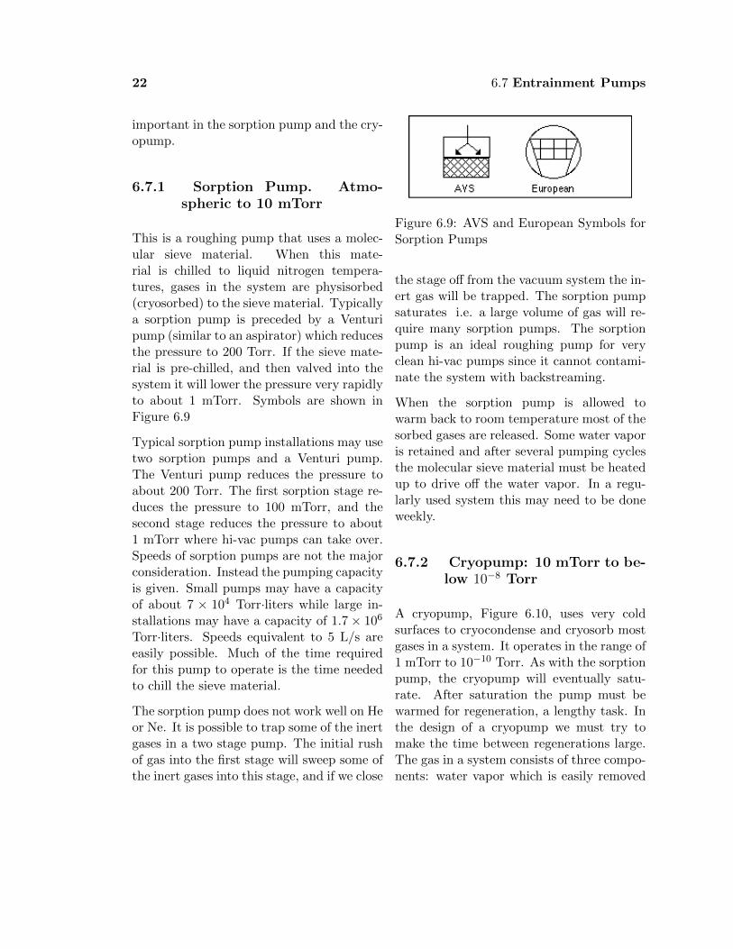
This is a roughing pump that uses a molec-ular sieve material. When this mate-rial is chilled to liquid nitrogen tempera-tures, gases in the system are physisorbed(cryosorbed) to the sieve material. Typicallya sorption pump is preceded by a Venturipump (similar to an aspirator) which reducesthe pressure to 200 Torr. If the sieve mate-rial is pre-chilled, and then valved into thesystem it will lower the pressure very rapidlyto about 1 mTorr. Symbols are shown inFigure 6.9
Typical sorption pump installations may usetwo sorption pumps and a Venturi pump.The Venturi pump reduces the pressure toabout 200 Torr. The first sorption stage re-duces the pressure to 100 mTorr, and thesecond stage reduces the pressure to about1 mTorr where hi-vac pumps can take over.Speeds of sorption pumps are not the majorconsideration. Instead the pumping capacityis given. Small pumps may have a capacityof about 7 × 10⁴ Torr·liters while large in-stallations may have a capacity of 1.7 × 10⁶
Torr·liters. Speeds equivalent to 5 L/s areeasily possible. Much of the time requiredfor this pump to operate is the time neededto chill the sieve material.
The sorption pump does not work well on Heor Ne. It is possible to trap some of the inertgases in a two stage pump. The initial rushof gas into the first stage will sweep some ofthe inert gases into this stage, and if we close
Figure 6.9: AVS and European Symbols forSorption Pumps
the stage off from the vacuum system the in-ert gas will be trapped. The sorption pumpsaturates i.e. a large volume of gas will re-quire many sorption pumps. The sorptionpump is an ideal roughing pump for veryclean hi-vac pumps since it cannot contami-nate the system with backstreaming.
When the sorption pump is allowed towarm back to room temperature most of thesorbed gases are released. Some water vaporis retained and after several pumping cyclesthe molecular sieve material must be heatedup to drive off the water vapor. In a regu-larly used system this may need to be doneweekly.
6.7.2 Cryopump: 10 mTorr to be-low 10−8 Torr
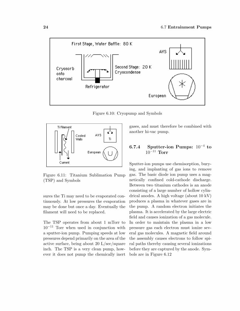
A cryopump, Figure 6.10, uses very coldsurfaces to cryocondense and cryosorb mostgases in a system. It operates in the range of1 mTorr to 10−10 Torr. As with the sorptionpump, the cryopump will eventually satu-rate. After saturation the pump must bewarmed for regeneration, a lengthy task. Inthe design of a cryopump we must try tomake the time between regenerations large.The gas in a system consists of three compo-nents: water vapor which is easily removed

6.7 Entrainment Pumps 23
at liquid nitrogen temperatures, active gaseswhich can be gettered, and inert gases whichmust be physisorbed.
Typically two stages are used. The firststage is cooled to about 80 K and cryocon-denses mostly water vapor. The secondstage is cooled to 15 K where it cryocon-denses the active gases in the system. Asorbing material such as charcoal is bondedto the 15 K surface and serves to cryosorbhydrogen and helium. These latter two gasesare pumped with much less efficiency thanother gases, and may not be pumped at allif the sorbant surface is saturated. Threestage designs which add a 4.2 K surface forenhanced pumping of H and He are not incommercial production. A closed cycle he-lium refrigerator is used to provide the lowtemperatures, and this accounts for much ofthe cost of the cryopump.
Cryopump speeds are large (10 L/s and up)and depend on the gas of interest.
The cryopump is very fast and very clean,and these features make it ideal for hi-vacwork in analytical instruments and micro-electronics applications. Ultimate pressuresbelow 10−6 Torr are possible. With carefuldesign UHV pressures down to 10−10 Torrare possible.
Table 6.6 presents info on He-lix Technology cryopumps (http://www.helixtechnology.com). Capac-ity is a measure of the total number ofmolecules that can be contained in thepump, given as Capacity =PV . For argonthe pressure used is 1 atmosphere (760Torr) while for hydrogen (present in verysmall amounts in the air) the pressure usedis 1 × 10⁻⁶ Torr.
Table 6.6: Cryopump specs for Cryo-TorrCryopump Models 8, 8F, and 10. Capac-ity =PV . For argon the pressure used is1 atmosphere (760 Torr) while for hydrogen(present in very small amounts in the air)the pressure used is 1 × 10⁻⁶ Torr.
Model 8 8F 10
Pumping SpeedsWater Vapor(L/s) 4000 4000 9000
Air(L/s) 1500 1500 3000Hydrogen(L/s) 2500 2200 5000
Argon(L/s) 1200 1200 2500Capacity, PV
Argon 1000 1000 2000Hydrogen 12 8 24
6.7.3 Titanium SublimationPump: 10−2 to below 10−11
Torr
The titanium sublimation pump (TSP), Fig-ure 6.11 operates primarily by chemisorptionor gettering of active gases. Since it does notpump inert gases it is generally used in con-junction with an ion pump. A filament ofa titanium-molybdenum alloy is surroundedby walls which may be left at room temper-ature or may be cooled by water or liquidnitrogen. Titanium can be sublimated fromthe filament onto the walls to form an atom-ically clean surface.
Chemically active gases combine with thefreshly evaporated titanium film. The ex-act reactions depend on the gas. As reac-tions take place, the Ti film saturates, anda new film must be deposited which buriesthe molecules previously gettered to the sur-face. The frequency of evaporations dependson the pressure in the system. At high pres-
24 6.7 Entrainment Pumps
Figure 6.10: Cryopump and Symbols
Figure 6.11: Titanium Sublimation Pump(TSP) and Symbols
sures the Ti may need to be evaporated con-tinuously. At low pressures the evaporationmay be done but once a day. Eventually thefilament will need to be replaced.
The TSP operates from about 1 mTorr to10−11 Torr when used in conjunction witha sputter-ion pump. Pumping speeds at lowpressures depend primarily on the area of theactive surface, being about 20 L/sec/squareinch. The TSP is a very clean pump, how-ever it does not pump the chemically inert
gases, and must therefore be combined withanother hi-vac pump.
6.7.4 Sputter-ion Pumps: 10−4 to10−11 Torr
Sputter-ion pumps use chemisorption, bury-ing, and implanting of gas ions to removegas. The basic diode ion pump uses a mag-netically confined cold-cathode discharge.Between two titanium cathodes is an anodeconsisting of a large number of hollow cylin-drical anodes. A high voltage (about 10 kV)produces a plasma in whatever gases are inthe pump. A random electron initiates theplasma. It is accelerated by the large electricfield and causes ionization of a gas molecule.In order to maintain the plasma in a lowpressure gas each electron must ionize sev-eral gas molecules. A magnetic field aroundthe assembly causes electrons to follow spi-ral paths thereby causing several ionizationsbefore they are captured by the anode. Sym-bols are in Figure 6.12

6.7 Entrainment Pumps 25
Figure 6.12: Symbols for Sputter Ion Pumps
Table 6.7: StarCell Sputter Ion TSP Com-binations Speeds in L/s
Vacion Plus 150 N2 610H2 1380
Vacion Plus 150 N2 720H2 1580
Vacion Plus 150 N2 880H2 1930
The ions are accelerated towards the cath-ode, and being more massive than the elec-trons are little affected by the magnetic field.When they strike the cathode they typicallybury themselves physically in the cathode,and at the same time eject (sputter) some ofthe titanium of the cathode. This titaniumdeposits elsewhere in the system providing agettering surface for active gases. Thus ionsare physically buried during the sputtering.Neutrals and inert gases are trapped eitherin by gettering with a fresh titanium surfaceor by being buried by newly sputtered tita-nium.
Clearly the ion pump does not remove themolecules from the system, it either gettersor captures them. Thus it has a finite op-erating lifetime after which it must be ”re-built” by being cleaned and by having freshtitanium applied to the cathodes. In nor-mal operation this must be done only afterseveral years of operation.
Active gases are both buried and gettered.The noble gases are only trapped by beingburied. Thus inert gases are pumped less ef-ficiently than active gases. Gases buried inthe cathode can be released at a later timeby another sputtering event, and this is espe-cially a problem for the inert gases. “Nobeldiode ion pumps” use tantalum on one cath-ode to better trap the inert gases. Specialion pumps exist for hydrogen as well. Hy-drogen diffuses easily through titanium, andso the cathodes are made thicker to absorbgreater amounts of hydrogen than the regu-lar pump.
Ion pump “triodes” also exist. These havecathodes which are strips of titanium ratherthan being a solid sheet. Some of the sput-tered titanium then can hit the walls of thepump, and act as a getter there. Gasestrapped or buried at the wall are not sub-ject to ion bombardment, and thus willbe trapped permanently. Triodes are alsoslightly better at pumping inert gases forreasons which are beyond the scope of thiscourse.
Sputter-ion pumps are available with pump-ing rates as high as 7000 L/s and operatebetween 10−2 Torr and 10−11 Torr. Anodesand cathodes can be replaced, and a typicallifetime is 50 000 hours at 10−6 Torr. Thepump is a clean pump.
Often Ion Pumps are paired with TitaniumSublimation Pumps such as the Varian “Vac-Ion Plus”pump.

26 6.8 Some Typical Systems
6.8 Some Typical Sys-tems
Three systems will briefly be described here,a general purpose hi-vac system, an ultra-hi-vac system capable of pressures as low as10−10 Torr, and a high gas-flow system capa-ble high-vacuum base pressures but operatedin the 1-100 mTorr range.
6.8.1 General Purpose Hi-VacSystem
The system in Figure 6.13 is capable ofhigh vacuum, 10−7 Torr, and is relativelyclean and inexpensive. It might be used forvacuum evaporation, vacuum sputtering, orplasma physics experiments.
Figure 6.13: General Purpose Vacuum Sys-tem
6.8.2 Ultra Hi-Vac System
The system in Figure 6.14 is very clean, andreaches ultra-high vacuum. It would be usedin surface analysis work such as XPS (X-rayPhotoelectron Spectroscopy.)
Figure 6.14: An UHV System suitable forlow gas flow applications
6.8.3 High Gas Flow System
Figure 6.15 shows a system suitable forvery clean, high vacuum applications wherea substantial gas flow might be required.It would find application in manufacturing-scale sputtering systems.
Figure 6.15: Vacuum System for High GasFlow Clean System

6.10 Summary 27
6.9 Capital Costs, Operat-ing Costs
Nothing doesn’t come cheap. Here I sum-marize the 2005 costs of a variety of pumpsand accessories. My sources are Varian Vac-uum Products and Kurt J. Leskar Company.Other vendors have high quality equipmentalso, these are chosen for convenience.
Consider a diffusion pump system suitablefor a small laboratory chamber of less than1000 L. A 6-inch diffusion pump system isappropriate. The following are significantitems.
For a large system, a Roots blower-rotarypump combination is very effective. A 50cfm (1300 L/min) rotary pump coupled witha Roots blower makes a combination effec-tive speed of 350 cfm (9300 L/min). Thecombination (Leskar VBPS350) costs $13200. This would be appropriate for a pro-duction system that might use a 50 000L/s diffusion pump on a 21 000 L chamber(7 × 10 × 10 feet).
Instead of a diffusion pump, we might wantto use a cryopump because of its cleanliness.Here are costs for a cryopump comparable inspeed to the VHS-6 diffusion pump.
Table 6.9: Cryopump System, Helix Tech-nology
Cryo-Torr 10 3000 L/s air $9 555Compressor $10 180Regenerator $1 900Thermometer $1 300
If we are looking for a small UHV system weuse different pumps. These might be appro-
priate choices.
The prices above are just for the pump-ing components of a system. We still needto specify and purchase the chamber, vac-uum gauges, equipment for the chamber,and assorted plumbing of water lines, pipes,etc.
In addition to the capital costs associatedwith the pumps, we must consider the oper-ating costs. These include the costs of elec-tricity, cooling water, liquid nitrogen as wellas maintenance costs. For an excellent dis-cussion, see O’Hanlon.
6.10 Summary
Several types of pumps have been outlinedin this chapter. As mentioned in the intro-duction, each has certain pressure ranges itoperates in and each has advantages and dis-advantages.
In choosing a system you must balance fac-tors of cost (both initial purchase price andoperating costs), cleanliness, and suitabil-ity for your application. By far the mostwidespread system in use today uses a ro-tary pump coupled with either a diffusionpump or a turbopump. In certain applica-tions however other types of pumps are thenorm.
Spend some time becoming familiar withyour pumping system and pay attention toservice intervals, safety aspects, and properoperating procedure. Vacuum pumps aregenerally quite reliable as long as they arenot too severely mistreated.

28 6.10 Summary
Table 6.8: Small Diffusion Pumped SystemVarian SD451 Rotary Pump 450 L/min, 17 cfm $3500
Rotary Pump Oil Leskar TKO-19 VP 8.8 × 10⁻⁹ Torr, 4L $15Varian VHS-6 Diffusion Pump 2400 L/s $4000
Cryotrap $2400Hi-vac gate valve $3000Roughing valves $800
Diffusion Pump Oil DC704 500 mL workhorse $103Fomblin Y06 500 mL high oxygen loads $138Santovac-5 500 mL oxidation resistant $1632
Table 6.10: UHV SystemVarian Vac-Sorb Sorption Pump 76 000 Torr-L $1 000Varian Vac-Ion Plus-150 Ion-Pump 150 L/s $4 600
Controller $3 200Varian TSP Titanium Sublimation $3 000
Controller $1 600Varian V150HT Turbo Pump 130 L/s $5 300
Controller $2 000Rotary pump, SD-40 $1 300