chapter 6 – parallel dc circuits introductory circuit analysis robert l. boylestad
TRANSCRIPT

Chapter 6 – Parallel dc Circuits
Introductory Circuit AnalysisRobert L. Boylestad

6.1 - Introduction
There are two network configurations – series and parallel.
In Chapter 5 we covered a series network. In this chapter we will cover the parallel circuit and all the methods and laws associated with it.

6.2 – Parallel Resistors
Two elements, branches, or circuits are in parallel if they have two points in common as in the figure below
Insert Fig 6.2Insert Fig 6.2

Parallel Resistors For resistors in parallel, the total resistance is
determined from
Note that the equation is for the reciprocal of RT rather than for RT.
Once the right side of the equation has been determined, it is necessary to divide the result into 1 to determine the total resistance
Parallel Resistors
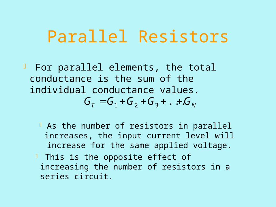
For parallel elements, the total conductance is the sum of the individual conductance values.
As the number of resistors in parallel increases, the input current level will increase for the same applied voltage.
This is the opposite effect of increasing the number of resistors in a series circuit.
NT GGGGG ...321

Parallel Resistors
The total resistance of any number of parallel resistors can be determined using
The total resistance of parallel resistors is always less than the value of the smallest resistor.
N
T
RRRR
R1
...1111
321

Parallel Resistors
For equal resistors in parallel:
Where N = the number of parallel resistors.


1/RT = 1/1 + ¼ + 1/5 = 1 + 0.25 + 0.2 = 1.45
RT = 1/1.45 = 0.69

Parallel Resistors
A special case: The total resistance of two resistors is the product of the two divided by their sum.
The equation was developed to reduce the effects of the inverse relationship when determining RT
RT = PRODUCT/SUM

RT = (3 x 6)/(3 + 6) = 18/9 = 2

Parallel Resistors
Parallel resistors can be interchanged without changing the total resistance or input current.
For parallel resistors, the total resistance will always decrease as additional parallel elements are added.

Using a protoboard to set up the circuit

6.3 – Parallel CircuitsVoltage is always the same across parallel elements.
V1 = V2 = E The voltage across resistor 1 equals the voltage across
resistor 2, and both equal the voltage supplies by the source.
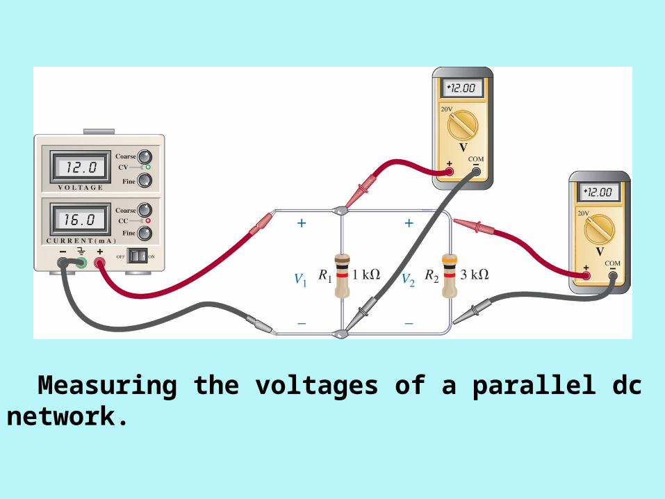
Measuring the voltages of a parallel dc network.

Parallel Circuits
For single-source parallel networks, the source current (Is) is equal to the sum of the individual branch currents.
21 IIIs For a parallel circuit, source current equals the sum
of the branch currents. For a series circuit, the applied voltage equals the sum of the voltage drops.

Parallel Circuits
For parallel circuits, the greatest current will exist in the branch with the lowest resistance.
2121 R
E
R
EIIIs

6.4 – Power Distribution in a Parallel Circuit
For any resistive circuit, the power applied by the battery will equal that dissipated by the resistive elements.
NRRRRE PPPPP ...321
The power relationship for parallel resistive circuits is identical to that for series resistive circuits.

Measuring the source current of a parallel network.

Measuring the current through resistor R1.

6.5 - Kirchhoff’s Current Law
Kirchhoff’s voltage law provides an important relationship among voltage levels around any closed loop of a network.
Kirchhoff’s current law (KCL) states that the algebraic sum of the currents entering and leaving an area, system, or junction is zero.
The sum of the current entering an area, system or junction must equal the sum of the current leaving the area, system, or junction.
outin II

Kirchhoff’s Current Law
Most common application of the law will be at the junction of two or more paths of current.
Determining whether a current is entering or leaving a junction is sometimes the most difficult task.
If the current arrow points toward the junction, the current is entering the junction.
If the current arrow points away from the junction, the current is leaving the junction.

Kirchhoff’s current law.

(a) Demonstrating Kirchhoff’s current law; (b) the water analogy for the junction in (a).

I3 = 5A and I4 = 4A
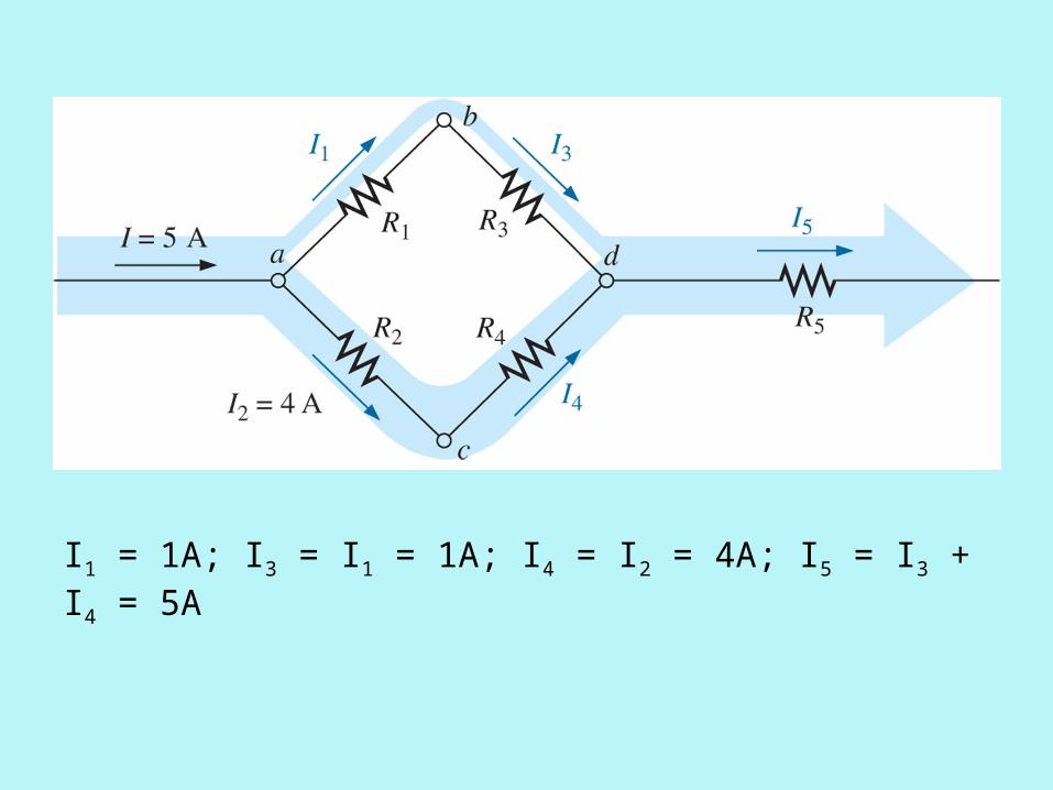
I1 = 1A; I3 = I1 = 1A; I4 = I2 = 4A; I5 = I3 + I4 = 5A

6.6 – Current Divider Rule The current divider rule (CDR) is used to find the
current through a resistor in a parallel circuit.General points:
For two parallel elements of equal value, the current will divide equally.
For parallel elements with different values, the smaller the resistance, the greater the share of input current.
For parallel elements of different values, the current will split with a ratio equal to the inverse of their resistor values.

Current Divider Rule
Tx
Tx I
R
RI

Using the current divider rule to calculate current I1
1/RT = 1/1k + 1/10k + 1/22k RT = 873
I1 = (RT/R1)IT = (873/1000)(12 mA) = 10.5 mA

6.7 - Voltage Sources in Parallel
Voltage sources are placed in parallel only if they have the same voltage rating.
The purpose for placing two or more batteries in parallel is to increase the current rating.
The formula to determine the total current is:
at the same terminal voltage.
21 intint
21
RR
EEI

Voltage Sources in Parallel
Two batteries of different terminal voltages placed in parallel
When two batteries of different terminal voltages are placed in parallel, the larger battery tries to drop rapidly to the lower supply
The result is the larger battery quickly discharges to the lower voltage battery, causing the damage to both batteries
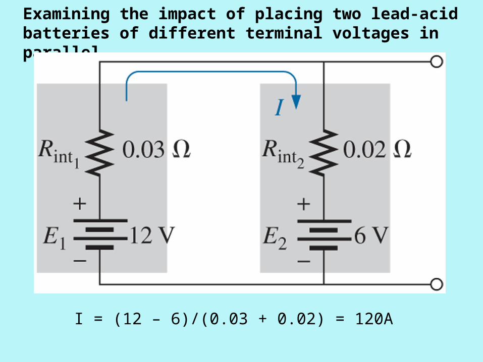
Examining the impact of placing two lead-acid batteries of different terminal voltages in parallel.
I = (12 – 6)/(0.03 + 0.02) = 120A

6.8 - Open and Short Circuits
An open circuit can have a potential difference (voltage) across its terminal, but the current is always zero amperes.

Open and Short Circuits A short circuit can carry a current of a level determined
by the external circuit, but the potential difference (voltage) across its terminals is always zero volts.
Insert Fig 6.44Insert Fig 6.44

I = (6V)/(12) = 0.5A and V = (0.5A)(10) = 5V

I = (6V)/(2) = 3A and V = 0

6.9 – Voltmeter Loading Effects
Voltmeters are always placed across an element to measure the potential difference.
The resistance of parallel resistors will always be less than the resistance of the smallest resistor.
A DMM has internal resistance which may alter the resistance of the network under test.
The loading of a network by the insertion of a meter is not to be taken lightly, especially if accuracy is a primary consideration.

Voltmeter Loading Effects
A good practice is to always check the meter resistance against the resistive elements of the network before making a measurement.
Most DMMs have internal resistance levels in excess of 10 M on all voltage scales.
The internal resistance of a VOM depends on the scale chosen.
Internal resistance is determined by multiplying the maximum voltage of the scale setting by the ohm/volt ( / V) rating of the meter, normally found at the bottom of the face of the meter.
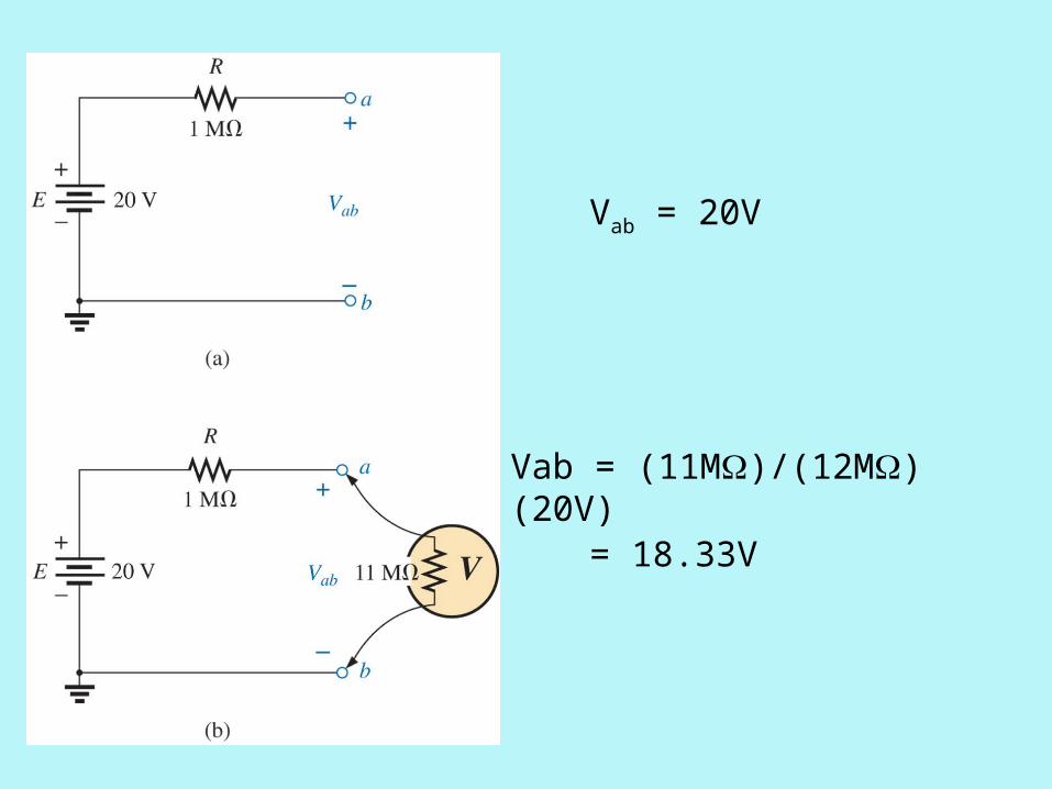
Vab = 20V
Vab = (11M)/(12M)(20V)
= 18.33V

6.11 – Troubleshooting Techniques
Troubleshooting is a process by which acquired knowledge and experience are employed to localize a problem and offer or implement a solution.
Experience and a clear understanding of the basic laws of electrical circuits is vital.
First step should always be knowing what to expect

6.13 – Applications
Car system The electrical system on a car is essentially a
parallel system. Parallel computer bus connections
The bus connectors are connected in parallel with common connections to the power supply, address and data buses, control signals, and ground.

Expanded view of an automobile’s electrical system.

Applications
House wiring Except in some very special circumstances the basic
wiring of a house is done in a parallel configuration. Each parallel branch, however, can have a
combination of parallel and series elements. Each branch receives a full 120 V or 208 V, with the
current determined by the applied load.

Single phase of house wiring: (a) physical details; (b) schematic representation.

Continuous ground connection in a duplex outlet.