chapter 6 lines and lettering. learning objectives identify the lines found on a given industry...
TRANSCRIPT
CHAPTER 6
Lines and Lettering
Learning Objectives
• Identify the lines found on a given industry drawing
• Draw ASME standard lines• Solve engineering given problems• Create ASME standard text• Answer questions related to lines
and lettering
Lines
• Must be of a quality that reproduces easily
• Dark, crisp, sharp, and of the correct thickness
• No variation in darkness• Variation in thickness• Thicker lines stand out clearly
• Thinner lines are subordinate
Mechanical Drafting Line Standards
• ASME Y14.2, Line Conventions and Lettering• Thick lines .02 in. (0.6 mm)
Twice as wide as thin lines• Thin lines .01 in. (0.3 mm)
Half as as wide as thick lines
• Military (MIL) standards (STD)• Thick• Medium• Thin
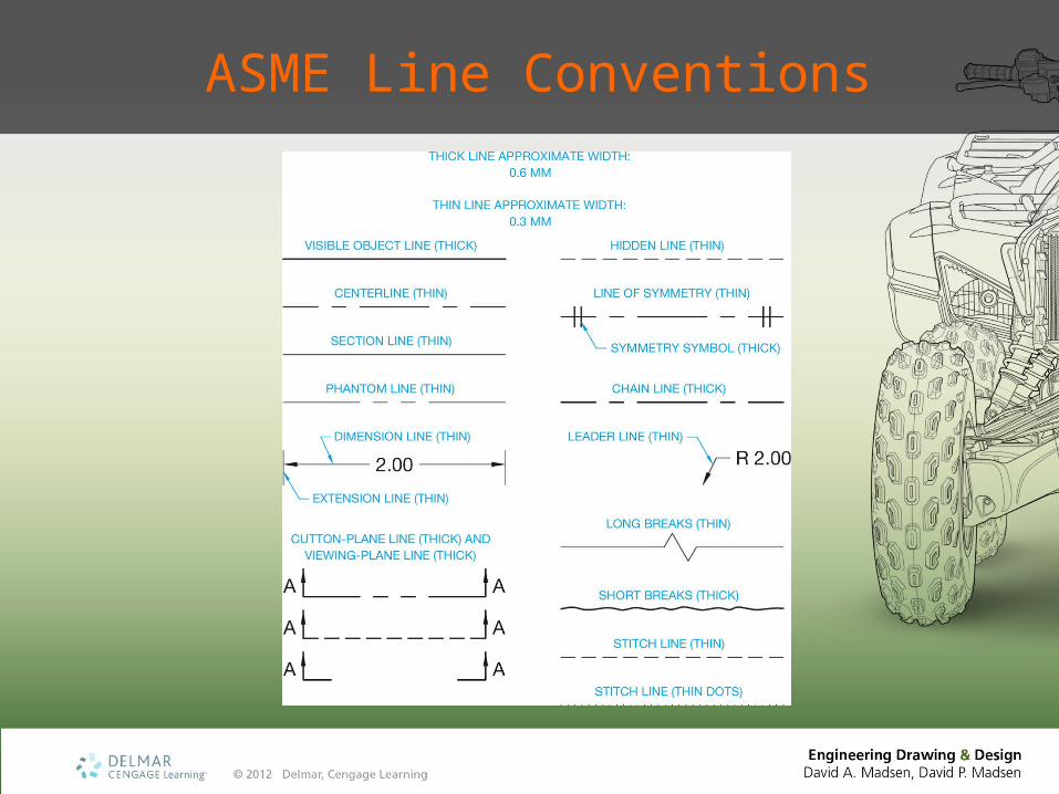
ASME Line Conventions
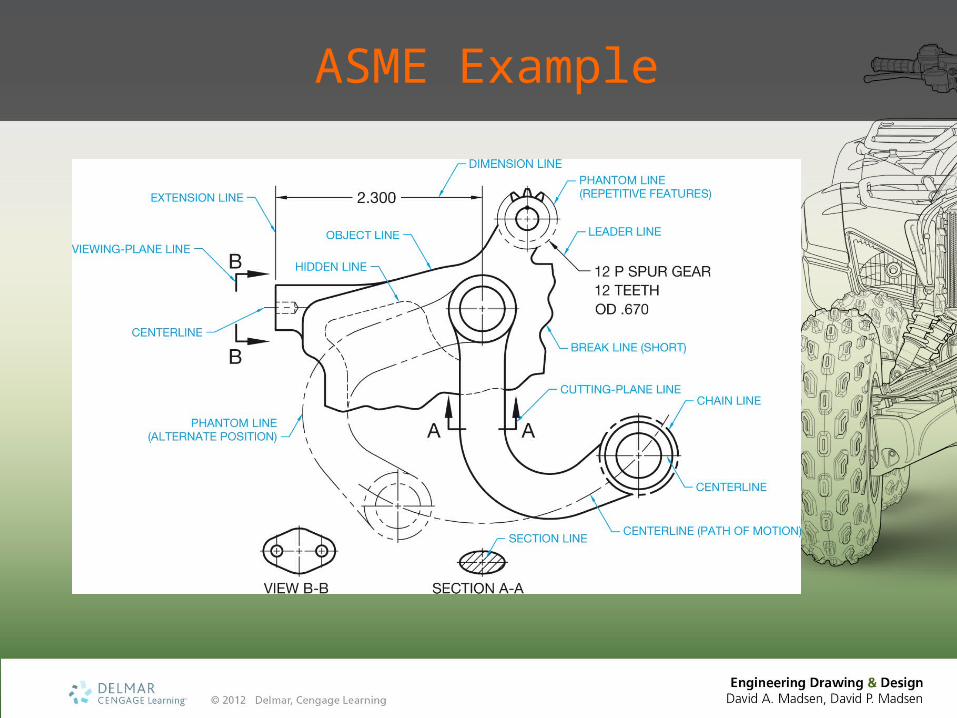
ASME Example
[Insert Figure 6.2]
Construction Lines
• Layout• Do not represent a specific
drawing feature• Not reproduced on the final
drawing
Visible Lines
• Object lines, or outlines• Visible surfaces or edges• Continuous (solid)• Thick• .02 in. (0.6 mm)
• ASME example
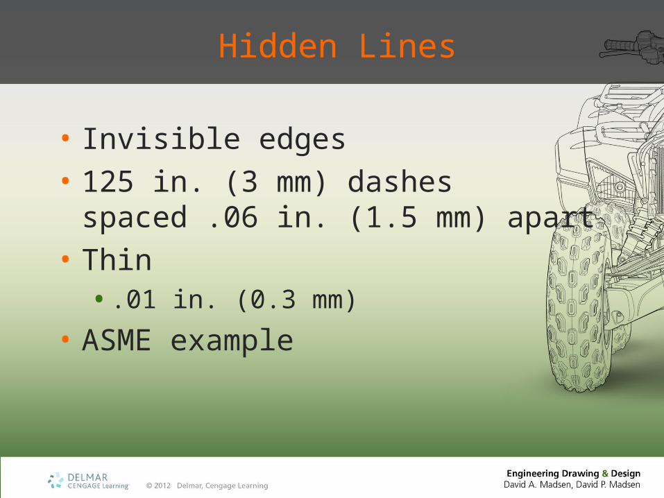
Hidden Lines
• Invisible edges• 125 in. (3 mm) dashes spaced .06
in. (1.5 mm) apart• Thin• .01 in. (0.3 mm)
• ASME example
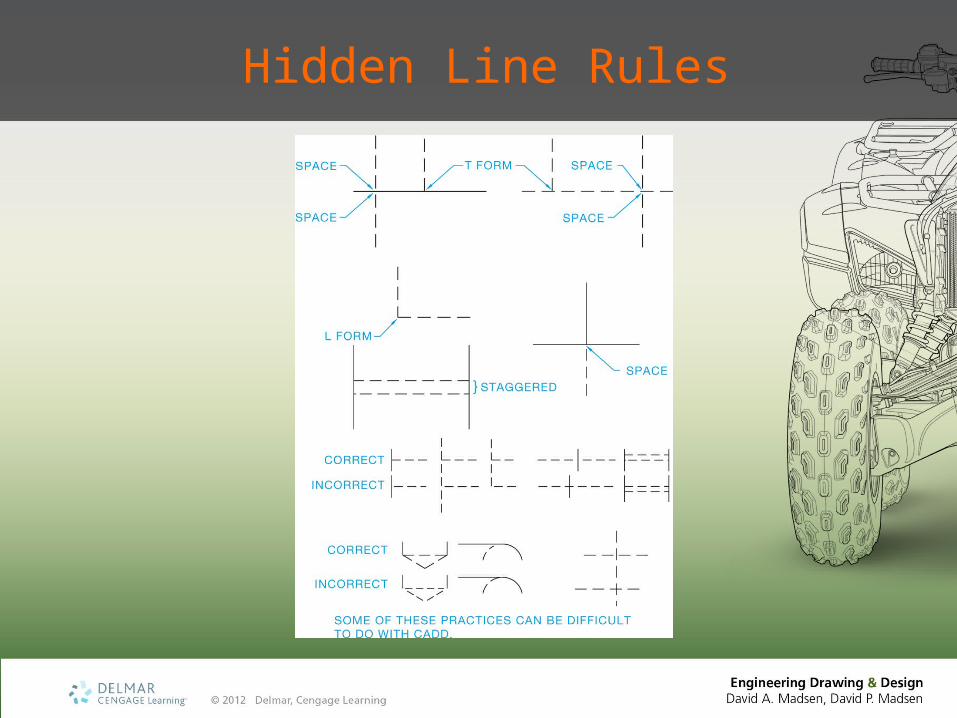
Hidden Line Rules
Centerlines
• Centers of circles and arcs• Center axis of a circular or
symmetrical form• Centers in a bolt circle pattern• Paths of motion in a mechanism
Centerlines
• Series of alternating long and short dashes• Long dash .75 to 1.50 in. (19-35 mm)
• Spaces between dashes .062 in. (1.5 mm)
• Short dash .125 in. (3 mm)
Centerlines
• Extend .125 in. (3 mm) or .25 in. (6 mm) past objects
• Thin• .01 in. (0.3 mm)
• ASME example
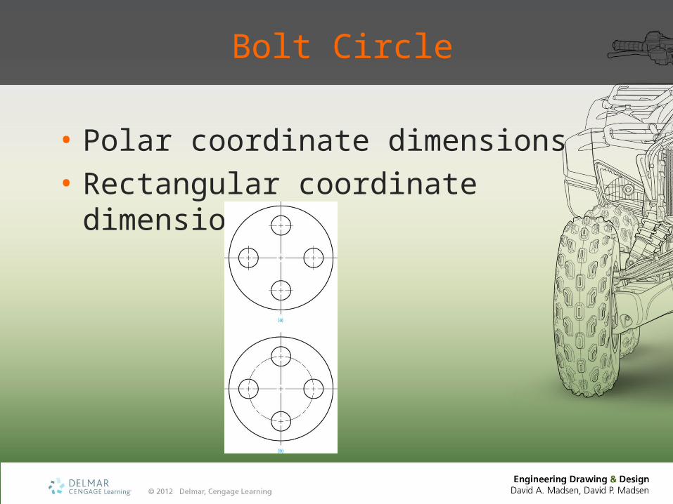
Bolt Circle
• Polar coordinate dimensions• Rectangular coordinate
dimensioning
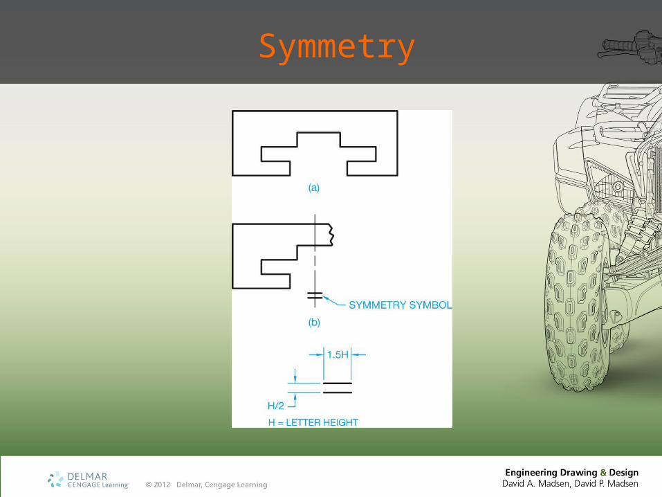
Symmetry
Extension Lines
• Establish the extent of a dimension• Begin with a .06 in. (1.5 mm)
space from the object• Extend .125 in. (3 mm) beyond the
last dimension• Thin• .01 in. (0.3 mm)
• ASME example
Extension Line Rules
• Can cross object lines, centerlines, hidden lines, other extension lines
• Should not cross dimension lines• Centerlines become extension
lines for dimensioning purposes
Dimension Lines
• Capped on the ends with arrowheads
• Broken to provide a space to indicate the length of the dimension
• Thin• .01 in. (0.3 mm)
• ASME example
Leader Lines
• Leaders• Connect a specific note to a
feature• Direct dimensions• Symbols• Item numbers• Part numbers
Leader Lines
• 45°, 30°, or 60° angles common• .125 to .25 in. (3-6 mm) shoulder
common• Pointing to a line: cap with an arrow• Pointing to a dimension line: no arrow• Pointing inside an object: cap with
a .05 in. (1.5 mm) dot
Leader Lines
• Continuous or hidden• Thin• .01 in. (0.3 mm)
• ASME example
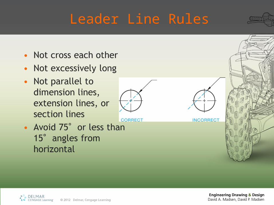
Leader Line Rules
Arrowheads
• Terminate dimension lines and leader lines• Cutting plane lines and viewing plane lines• Twice as big as arrowheads on dimension and
leader lines• Three times as long as wide• .125 in. (3 mm) long for dimension lines and
leader lines• Consistent sizes• Open or filled• ASME example
Cutting-Plane and Viewing-Plane Lines
• Thick• .02 in. (0.6 mm)
• Takes precedence over the centerline
• ASME example
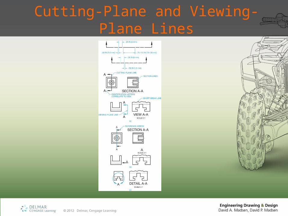
Cutting-Plane and Viewing-Plane Lines
Section Lines
• Appear in the view of a section• Show where the cutting-plane line
cuts through material• 45°, 30°, or 60°angles common• Thin• .01 in. (0.3 mm)
• ASME example
Section Line Rules
• Equally spaced• ASME minimum space .06 in. (1.5 mm)
• Avoid 75°or less than 15°angles from horizontal
• Not parallel or perpendicular to object lines• Opposite directions on adjacent parts• Thin parts can be shown without section
lining• Omit around text when necessary to have
text in a sectional view
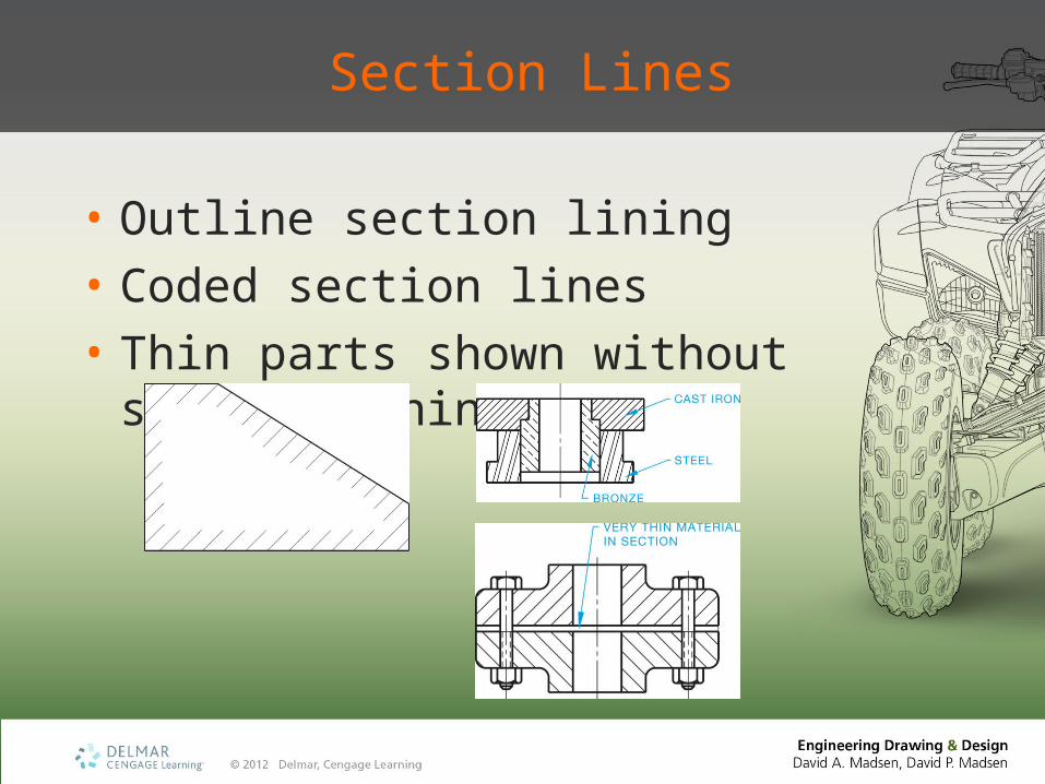
Section Lines
• Outline section lining• Coded section lines• Thin parts shown without section
lining

Short Break Lines
• Shorten the length of a long object or part
• Provide a partial view of a feature• Thick• .02 in. (0.6 mm)
• ASME example
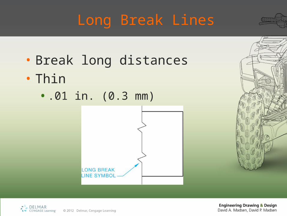
Long Break Lines
• Break long distances• Thin• .01 in. (0.3 mm)
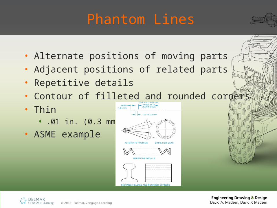
Phantom Lines
• Alternate positions of moving parts• Adjacent positions of related parts• Repetitive details• Contour of filleted and rounded corners• Thin• .01 in. (0.3 mm)
• ASME example
Chain Lines
• Indicate specified treatment• Projected tolerance zone• Alternately spaced long and short
dashes• Thick• .02 in. (0.6 mm)
• ASME example
Stitch Lines
• Indicate the location of stitching or sewing
• Short thin dashes, or• .01 in. (0.3 mm) diameter dots
spaced .12 in. (3 mm) apart
Lettering
• Dimensions• Notes• Titles
Lettering
• Must be of a quality that reproduces easily
• Dark, crisp, sharp• CADD text• Font
ASME Lettering Standards
• ASME Y14.2, Line Conventions and Lettering• Opaque
• Clearly spaced
• Vertical or inclined
• One style
• Upper case letters
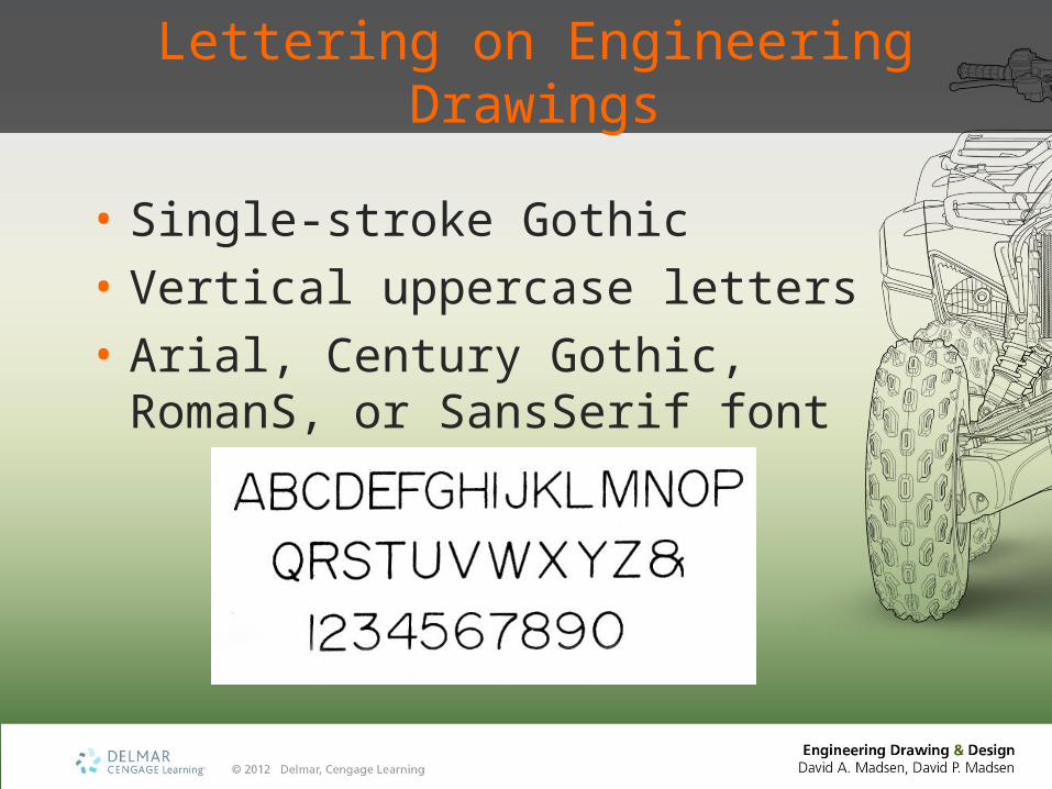
Lettering on Engineering Drawings
• Single-stroke Gothic• Vertical uppercase letters• Arial, Century Gothic, RomanS, or
SansSerif font
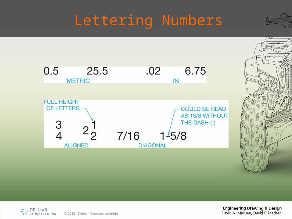
Lettering Numbers
Inclined and Lowercase Lettering Styles
• Inclined• 68°to the right from horizontal
• Structural drafting
• Civil drafting or maps
• Lowercase• Uncommon in mechanical drafting
• Engineering specifications
• Civil drafting or maps
Architectural Lettering
• Traditional freehand architectural lettering with an artistic flair• StylusBT, ArchiText, CountryBlueprint,
or CityBlueprint fonts
• United States National CAD Standard (NCS)• SansSerif font
Lettering Legibility
• Background area between letters:• Approximately equal
• Individual words clearly separated• Space between two numerals with a
decimal point between:• Minimum two-thirds the lettering height
• Vertical space between lines of lettering• No more than the lettering height, no less
than half the lettering height
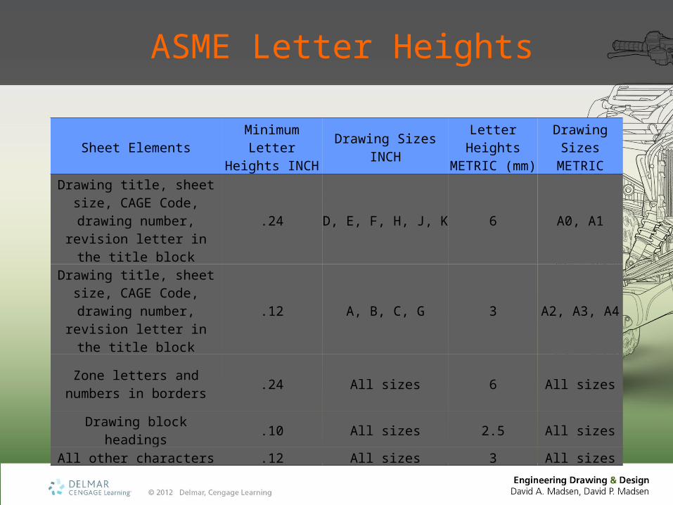
ASME Letter Heights
Sheet ElementsMinimum
Letter Heights INCH
Drawing Sizes INCH
Letter Heights METRIC (mm)
Drawing Sizes
METRIC
Drawing title, sheet size, CAGE Code, drawing
number, revision letter in the title block
.24 D, E, F, H, J, K 6 A0, A1
Drawing title, sheet size, CAGE Code, drawing
number, revision letter in the title block
.12 A, B, C, G 3 A2, A3, A4
Zone letters and numbers in borders
.24 All sizes 6 All sizes
Drawing block headings .10 All sizes 2.5 All sizesAll other characters .12 All sizes 3 All sizes
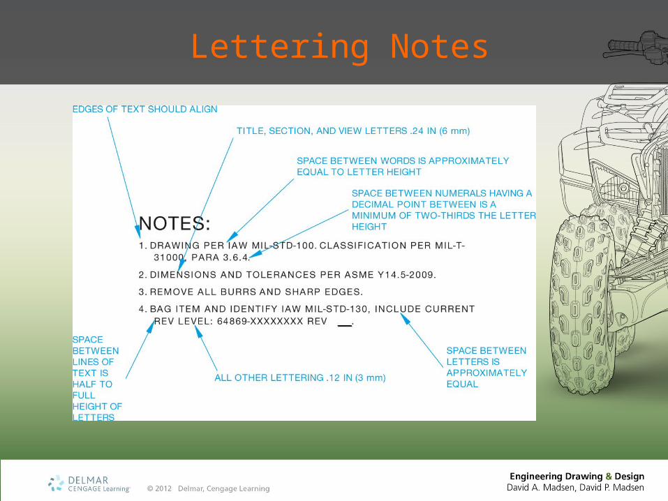
Lettering Notes