chapter 5 repair of concrete structure …5-2 5.2 case of concrete structure repair this section is...
TRANSCRIPT

5-1
CHAPTER 5 REPAIR OF CONCRETE STRUCTURE 5.1 Planning of Concrete structure repair Before repair work, approximate concrete bridge repair plan and cost shall be prepared. In this manual, it is recommended that the planning and cost estimate should be done. This manual covers ‘repair plan’ and ‘repair cost’. The repair plan shall include;
- Province (DPWT) that manages target bridge sections - Location - Work priority - Repair method - Reference No. of unit costs for cost estimate (refer to “Appendix”), and - Total repair cost
Rough bridge repairing cost can be obtained by summing up unit cost estimates. The typical repair code is shown in Table5.1.1. All repair codes are described in ‘Appendix’
No. Code Repair Work Unit
1 1001 Concrete Crack Repair m
2 1002 Concrete Defect repair m3
3 1003 Concrete Surface Reinforcement m2
4 1004 Reinforcement by Steel Plate m2
In the repair execution plan, work priority order has to be determined with comprehensive consideration of progressive speed, location and current severity of damages plus route importance and preference. Since the bridge maintenance technology is constantly evolving, road administrator must keep obtaining new knowledge by dense communication and information exchange to relevant organizations.
Table 5.1.1Typical bridge repair code (Concrete)

5-2
5.2 Case of Concrete structure repair This section is introduced to repair cases of concrete structures.
C-1 Concrete crack
(a) Conditions
There are alligator cracks or multiple numbers of linear cracks on the sides of concrete piers, and their width is more than 0.3mm (Photo 5.2.1.1). If this situation remains untreated, corrosion of reinforcements is in danger of progressing. As a result, spalling and decrease of concrete strength might occur in the future (Fig. 5.2.1.1).
Photo 5.2.1.1 Concrete crack on pier
Fig. 5.2.1.1 Progress of concrete crack

5-3
(b) Possible Causes Though there are some possible causes of the damage such as dry shrinkage during construction, it is difficult to identify to the one. However, since many similar cracks exist in multiple directions and locations, the excessive external load from overloading vehicles can be excluded.
(c) Outline of repairs Concrete cracks are filled with epoxy resin injection (Photo 5.2.1.2). The procedures are as follows:
(1) Preparing of material (Photo 5.2.1.3)
* Epoxy resin and hardener *Sealant (Sealing) *Syringes set
Photo 5.2.1.2 Concrete crack repair method
Photo 5.2.1.3 Concrete crack repair material
Syringes set
Epoxy resin Sealant
①Washer
②Syringes
③Rubber Band
④Pressure Ring
⑤Stopper

5-4
(2) Execution Procedures This repair work is carried out by dividing three days (Fig. 5.2.1.2).
①1st day
Removing the dirt Sealing
②2nd day ③3rd day
Injection into cracks with epoxy resin Remove syringes, washers and sealing
After sealing become hardened (24 hours after)
After Injection material becomes hardened (24 hours after)
Fig. 5.2.1.2 Outline of crack repair method by Epoxy Resin

5-5
Work procedure 1) Measuring cracks (1st day)
To decide which cracks to be repaired, the width of cracks was measured and marked. And the length of cracks to be repaired was also measured and marked (Photo 5.2.1.4).
2) Cleaning the cracks (1st day) To attach sealing and injection material well, cracks were cleaned by using wire brush (Photo 5.2.1.5) and air blower (Photo 5.2.1.5) along the crack for 50mm wide on both sides. Oil also should be wiped off with thinner.
3) Determining washer setting points (1st day) Washer setting points are marked by chalk. (Photo 5.2.1.6) Their standard interval is 4 points per 1m.
Photo 5.2.1.4 Deciding repair range
Photo 5.2.1.5 Surface Preparation
Photo 5.2.1.6 Determining injection points
(a) Wire brush (b) Air blower

5-6
4) Mixing sealing material (1st day) Sealing material consists of ‘Main material’ and ‘Hardener’ (Photo 5.2.1.7). Defined amounts of ‘Main material’ and ‘Hardener’ are weighed (Photo 5.2.1.8) and mixed to knead up to uniform texture (about 3 minutes) (Photo 5.2.1.9).
(Mixing Ratio (Weight); Main material: Hardener = 2:1) After the materials are mixed, the material starts to become hard. It is necessary to mix well and use the material within 30 min. after starting mixing time (30 degree Celsius). Therefore, the mixing time (about 3 min.) and using time (30 min.) was measured by using a stopwatch.
Photo 5.2.1.7 Sealing material
Main material Hardener 2 : 1
Photo 5.2.1.8 Weighing material (Sealing material)
Photo 5.2.1.9 Mixing material (Sealing material)
Mixed to knead up to uniform texture
Quantity of sealing material used 0.3kg/m (Depend on the worker’s skill)
Mixing Ratio (Weight)
5-7
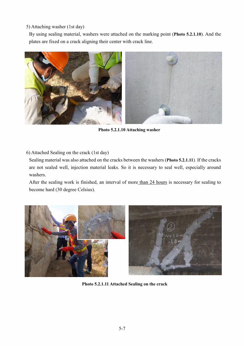
5) Attaching washer (1st day) By using sealing material, washers were attached on the marking point (Photo 5.2.1.10). And the plates are fixed on a crack aligning their center with crack line.
6) Attached Sealing on the crack (1st day) Sealing material was also attached on the cracks between the washers (Photo 5.2.1.11). If the cracks are not sealed well, injection material leaks. So it is necessary to seal well, especially around washers. After the sealing work is finished, an interval of more than 24 hours is necessary for sealing to become hard (30 degree Celsius).
Photo 5.2.1.10 Attaching washer
Photo 5.2.1.11 Attached Sealing on the crack

5-8
7) Mixing epoxy resin material (2nd day) Epoxy resin material consists of ‘Main material’ and ‘Hardener’ (Photo 5.2.1.12). Defined amounts of ‘Main material’ and ‘Hardener’ are weighed (Photo 5.2.1.13) and mixed to knead up to uniform texture (about 3 minutes) (Photo 5.2.1.14).
(Mixing Ratio (Weight); Main material: Harder = 2:1) After the materials are mixed, the material starts to become hard. It is necessary to mix well and use the material within 30 min. after starting mixing time (30 degree Celsius).Therefore, the mixing time (about 3 min.) and using time (30 min.) was measured by using a stopwatch.
Hardener Main material 1 : 2
Mixing Ratio (Weight)
Photo 5.2.1.12 Sealing material
Photo 5.2.1.13 Weighing material (Epoxy resin material)
Photo 5.2.1.14 Mixing material (Epoxy resin material)
Mixed to knead up to uniform texture

5-9
8) Epoxy resin injecting (2nd day) Epoxy resin material was inserted into syringes with rubber band (Photo 5.2.1.15). Then, stoppers of syringes are set (locked) so that the syringes don’t move (Photo 5.2.1.16). After the syringes were set on the washers (Photo 5.2.1.17), stoppers of the syringes were removed (unlocked) and the injection started by rubber pressure. Do not remove any syringes until the curing is completely made. After the injection work is finished, longer than 24 hours interval is necessary for epoxy resin material to become hard (30 degree Celsius).
Photo 5.2.1.15 Inserting into syringes
Photo 5.2.1.16 Stoppers of the syringes
Rubber band
Stopper
(a)Unlocked (b)Locked
Photo 5.2.1.17 Syringes set

5-10
9) Removing syringes and washers (3rd day) After Injection material became hard, the syringes and washers were removed (Photo 5.2.1.18).
10) Completion (Photo 5.2.1.19) (3rd day) Excess resin and dirt attached on the surface beyond repair section should be removed. Work site must be cleared. And used equipment shall be checked, cleaned.
(d) Remarks The cost of resin injection method for concrete crack repairing is relatively less expensive than other method (Fig 5.2.1.3). In case that the cause of the concrete cracks is not caused by external loading, repair budget is saved in the long run by this simple and reasonable method while the degree of cracks remains small.
Photo 5.2.1.18 Removing syringes and washers
Photo 5.2.1.19 Completion
(a)Removed syringes (b)Removed washer

5-11
Counter measures
Counter measures
Counter measures
Counter measures
Cost and scale of repair work
★
Cost and scale of repair work
★★
Covering the exposed rebar with mortar
Cost and scale of repair work
★★★
Cost and scale of repair work
★★★★
Detachment
Rusting factors Rusting factors
Rusting factors
Rusting factors
Rusting factors
Reinforcement
Replacement
Load
Load
Rusting of rebar
Expanding of rebar by rusting
Rebar is eaten away by rusting
Further damage
By expanding pressure, surface
concrete becomes detached
The whole structure becomes
weaker and weaker
Collapse
Fig. 5.2.1.3 Progress of concrete crack
Low cost!!

5-12
C-2 Carbon Fiber Cloth (CFC) Reinforcement Method (a) Introduction 1) Introduction It analyzed the damage cause of the bridge in Cambodia from the inspection results. The followings are the main causes of bridge collapse or serious damage in Cambodia; Case1: Insufficient strength capacity due to non-conforming work or design deficiency (Photo 5.2.2.1) Case2: Overloading (Photo 5.2.2.2)
Basic policy of these countermeasures is shown following Case1: Structural reinforcement bridge members in order to recover the losing strength Case2: Strengthening law enforcement of overloading vehicles and structural reinforcement of bridge members in order to increase the strength capacity Therefore as a feasible solution for the two main damages causes, structural reinforcement of bridge
‘Thickness of deck slab’ and ‘rebar volume’ are not enough
Photo 5.2.2.1 Insufficient strength capacity
Photo 5.2.2.2 Overloading

5-13
members’ must be performed. The structural reinforcement methods are shown in Table 5.2.2.1 Methods often applied for slab reinforcements are concrete overlaying, steel plate bonding and CFC (Carbon Fiber Cloth) bonding. In case of concrete overlaying and steel plate bonding methods, dead load is greatly increased by reinforcement. Therefore it is necessary to re-examine the capacity of existing girders, piers, and bearings. And according to the calculation, there is a case that requires redesigning for bearing replacement and pier reinforcement. (In case of re-designing, structural calculation reports and design drawing of existing bridge should be prepared.)
Concrete overlaying Steel plate bonding CFC bonding
Repair
Method
Increasing the thickness of
concrete slab from the surface
Bonding steel plate from slab
bottom with adhesive and anchor
bolts
Bonding CFSR from slab bottom
with adhesive
Merits
Scaffolding not needed No traffic regulation
needed
Many applications for busy
bridges in Japan
No traffic regulation
needed
Incremental weight is
very small
Easier construction
procedure
Demerits
Big incremental weight
Heavy equipment needed
Chipping of existing
concrete is necessary for
firm fixing
Road closure is needed
during construction
Big incremental weight
Heavy equipment needed
Scaffolding is needed
Anchor’s holding
capacity is not guaranteed
if the existing concrete is
poor
Scaffolding is needed
Risk of energization
Judgment Medium Not good Good
Table 5.2.2.1 The selection of concrete slab reinforcement method

5-14
2) Features of CFC The reinforcement is generally used as CFC (Photo 5.2.2.3) which is impregnated carbon fiber with resin, bonded and hardened on the concrete surface. CFC reinforcement method merits are shown following. -Excellent material properties. -Lightweight -High strength, high elasticity (Tensile strength: 3,400N/mm2, 10 times more compared with iron) -High durability against ultraviolet ray -Excellent workability Density of CFC is approximately 1.6 g/cm3, and is only 1/5 compared to the density of steel. Therefore, there is very little weight increase if you reinforce by this material. And CFC tensile strength of High strength is greater than 3,400 N/mm2. That means that it has ten times or greater than the tensile strength of steel. There is very little size increase of concrete structure, even after CFC strengthening. It is thickness less than 0.35mm. The unidirectional CFC has a high performance only in one direction. Therefore only one direction can be reinforced by the unidirectional CFC. In another way, if ‘both directions CFC’ is used, bi-direction can be reinforcement.
Photo 5.2.2.3 CFC (Carbon Fiber Cloth)
5-15
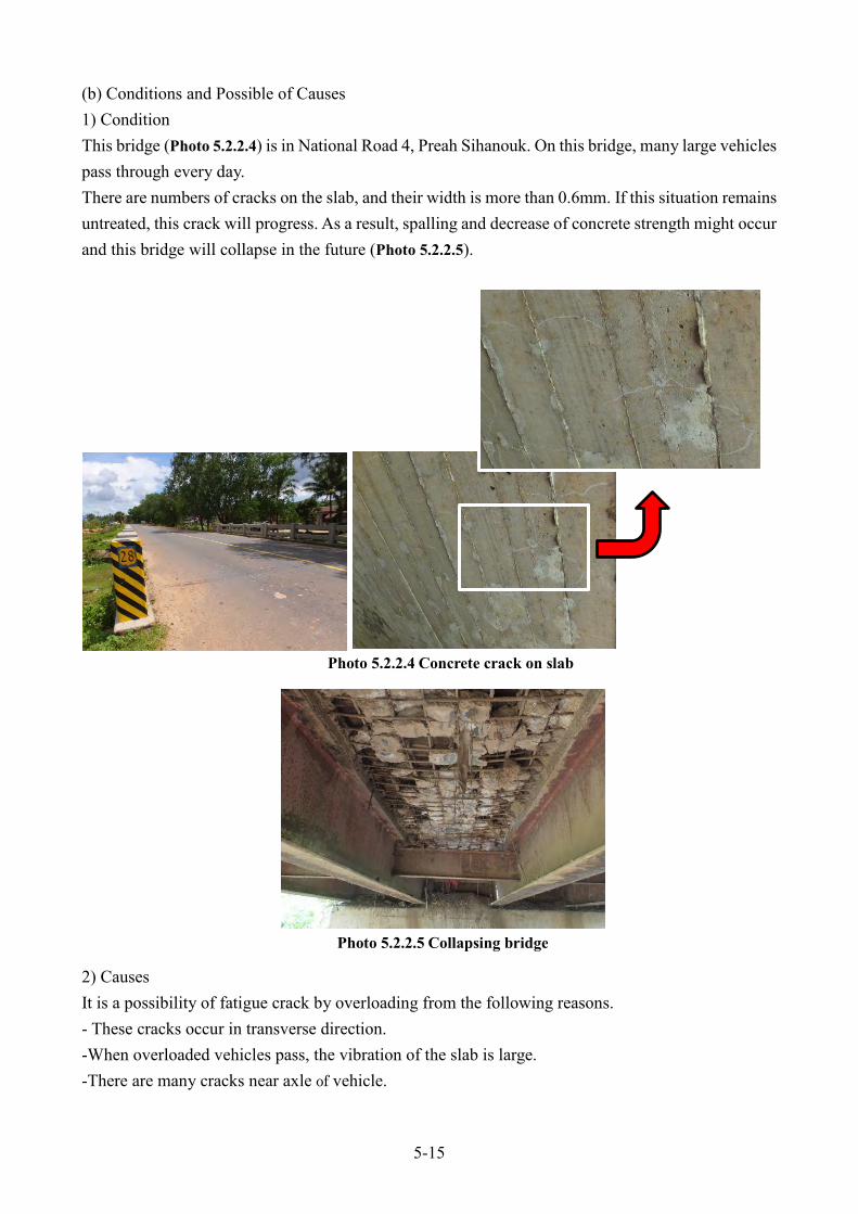
(b) Conditions and Possible of Causes 1) Condition This bridge (Photo 5.2.2.4) is in National Road 4, Preah Sihanouk. On this bridge, many large vehicles pass through every day. There are numbers of cracks on the slab, and their width is more than 0.6mm. If this situation remains untreated, this crack will progress. As a result, spalling and decrease of concrete strength might occur and this bridge will collapse in the future (Photo 5.2.2.5).
2) Causes It is a possibility of fatigue crack by overloading from the following reasons. - These cracks occur in transverse direction. -When overloaded vehicles pass, the vibration of the slab is large. -There are many cracks near axle of vehicle.
Photo 5.2.2.5 Collapsing bridge
Photo 5.2.2.4 Concrete crack on slab

5-16
(c) Outline of repair This method is the reinforcement of concrete structure by CFC. This method can be reinforced by hand without some heavy equipment because of a very light weight of CFC. In addition, CFC can be cut by scissors as you would like. Therefore CDC can be adjusted freely and flexibly with the surface of concrete. The standard usage weight per unit area of epoxy resin is shown in Table 5.2.2.2. The execution of the little resin weight causes the deterioration of the reinforcement.
Type of resin Areal weight of CFC
(g/m2)
Standard usage weight per unit area (kg/m2)
Under applying Over applying Total
Primer - - - 0.20
Smoothing Agent - - - 1.00
Impregnating resin 400 0.50~0.60 0.50~0.40 1.00
CFC - 1 - -
* It depends on the type of CFC.
Required tools for CFC reinforcement are shown in Table 5.2.2.3.
Process Tool Photo
Protection tool Gloves
Protect glass
Helmet
Table 5.2.2.2 The standard usage weight of epoxy resin (per unit area)
Table 5.2.2.3(a) Required tools for CFC reinforcement

5-17
Process Tool Photo
Protection tool Mask
a Raincoat
Sectional repair Surface preparation
Chalk
Wire brush
Blower
Crack gauge, Steel Tape
Table 5.2.2.3(b) Required tools for CFC reinforcement

5-18
Process Tool Photo
Sectional repair Surface preparation
Thermo-
hygrometer
Disk grinder
Pail
Pan balance
Stopwatch
permanent marker
Table 5.2.2.3(c) Required tools for CFC reinforcement

5-19
Process Tool Photo
Sectional repair Surface preparation
Spatula
Board (Plastic type)
Bucket
Polishing sheet
Trowel
Box cutter, and Scissors
Table 5.2.2.3(d) Required tools for CFC reinforcement

5-20
Process Tool Photo
Agitator (Low speed type)
Application roller (Handle)
Application roller (Roller)
Brush
Paddle Roller
Table 5.2.2.3(e) Required tools for CFC reinforcement

5-21
Process Tool Photo
For tool clean and for keeping clean site
Picnic sheet (Plastic type)
Paper towel
Thinner
Garbage bag
Tongs
Table 5.2.2.3(f) Required tools for CFC reinforcement

5-22
Work procedure The purpose of this method is bridge reinforcement. Therefore, it is necessary to repair work before implementing this method. Also, it is necessary to measure repair and reinforcement part and to reflect them in the work plan before site work. This workflow of CFC is shown in Fig. 5.5.2.1.
(1)Advance reinforcement work 1) Bridge inspection Inspection and recording should be done so that you can make work plan. Therefore, the bridge inspection should be done at first. And if there is crack wider than 0.3mm on the bridge, this crack must be repaired. In addition, by hammering inspection, we check detached sections and remove them. We measure the reinforcing range and record it on the expansion plan. (Photo 5.2.2.6)
2) Sectional repair The oversight of hollows and cracks causes bad bonding. Therefore if there is lacking parts and the hollows in concrete, it must be repair by resin mortar. And if there is crack wider than 0.3mm, it must be repair by epoxy resin (Fig. 5.2.2.2, Photo 5.2.2.7). (Reference: Crack repair method is shown in C-1 Concrete crack)
(2) CFC reinforcement work
Photo 5.2.2.6 Measure the reinforcing range
(1) Advance reinforcement work Bridge repair work
Fig. 5.2.2.1 Workflow of CFC

5-23
3) Surface Preparation (Fig. 5.2.2.3) Surface difference in level or edge of the corner causes bad bonding and break of carbon fiber. Therefore, surface difference is flatten on the concrete surface by disk grinder (Photo 5.2.2.8(a)) (less than 1mm difference in level) or put resin mortar (larger than 30mm in radius). And such as mortar, oil and dust are removed to expose the sound concrete by a disk grinder or a wire brush and a polishing scrubbing (Photo 5.2.2.8(b)).
Hollow Crack Fill a hollow with resin
mortar Inject into a crack with
epoxy resin
Cross section of slab
Photo 5.2.2.7 Crack repair (Reference: C-1 Concrete crack)
Fig. 5.2.2.2 Crack and hollow repair

5-24
Make a slope with resin mortar
Remove an edge using a grinder
Clean concrete surface
Cross section of slab
(a) To flatten by disk grinder (b) To remove dust by polishing scrubbing
Photo 5.2.2.8 Surface Preparation
Fig. 5.2.2.3 Surface Preparation
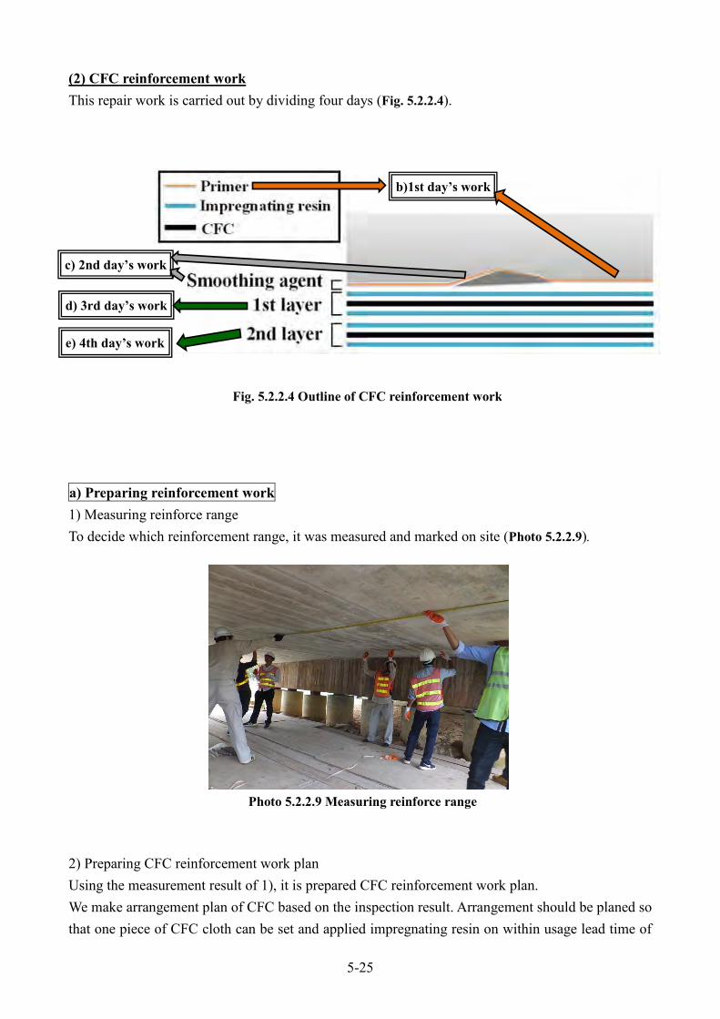
5-25
(2) CFC reinforcement work This repair work is carried out by dividing four days (Fig. 5.2.2.4). a) Preparing reinforcement work 1) Measuring reinforce range To decide which reinforcement range, it was measured and marked on site (Photo 5.2.2.9). 2) Preparing CFC reinforcement work plan Using the measurement result of 1), it is prepared CFC reinforcement work plan. We make arrangement plan of CFC based on the inspection result. Arrangement should be planed so that one piece of CFC cloth can be set and applied impregnating resin on within usage lead time of
b)1st day’s work
c) 2nd day’s work
d) 3rd day’s work
e) 4th day’s work
Fig. 5.2.2.4 Outline of CFC reinforcement work
Photo 5.2.2.9 Measuring reinforce range

5-26
the impregnating resin (about 30 minutes). At that time, splice should be considered (Fig. 5.2.2.5, Table 5.2.2.4).
CFC should be executed each other without any gap or wrapped them each other. An allowance of wrap (l0) is between 0 to 20mm (Fig. 5.2.2.6).
Purpose Splice length (L) Detached (Ld)
Strengthening of bending, shearing ≧ 200mm ≧ 300mm
Splice
Fiber direction
Interval Splice Splice
L Ld L
Table 5.2.2.4 Splice length
Fig. 5.2.2.5 Splice of CFC
Fig. 5.2.2.6 Allowance of wrap

5-27
On December 2016 - February 2017, CFC reinforcement work was carried out in Preah Sihanouk (Photo 5.2.2.4, Table 5.2.2.5).
Province Preah Sihanouk
Road Name National road 4
Bridge Name Tro paing Sa-Ou
Latitude, Longitude 10.667072, 103.794133
Number of span 2span
Concrete Bridge
Bridge width 9.9m
Bridge length 7.5m + 7.3m
Number of lane 2 lane
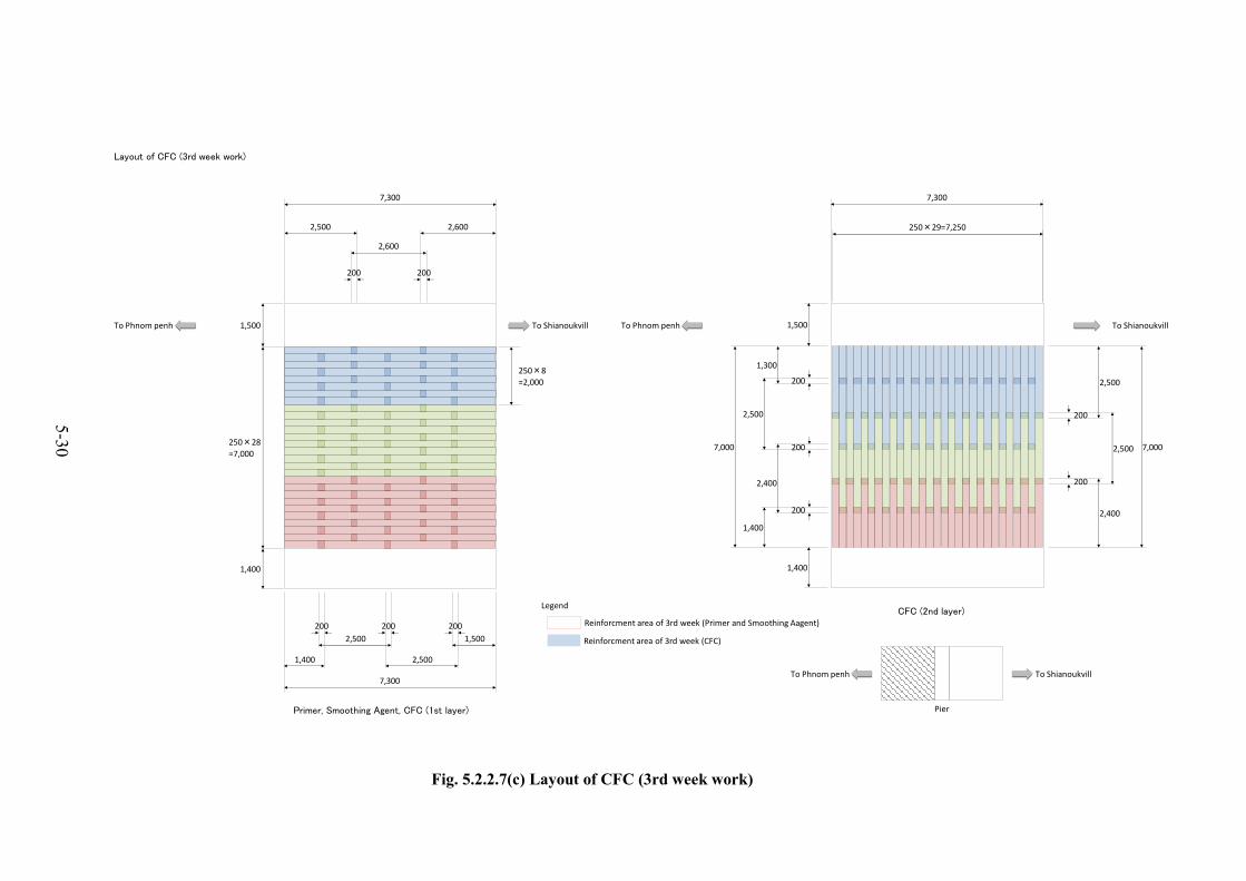
Using the measurement result, it was prepared this CFC reinforcement work plan before site work. The layout plan of CFC is shown in Fig 5.2.2.7. The material use plan is shown in Fig 5.2.2.8. The resin mix plan of CFC is shown in Fig 5.2.2.9.
Table 5.2.2.5 Various factors of target bridge

5-28
Layout of CFC (1st week work)
CFC (2nd layer)
Primer, Smoothing Agent, CFC (1st layer)
2,500
2,600
200 200
2,600
7,300
1,400
2,500
200 200
2,500
1,500
200
1,400
1,500
250×28
=7,000
7,300
7,300
1,400
1,500
2,400
2,500
200
7,000
2,500
200
1,300
2,500
2,400
1,400
7,000 200
200
250×29=7,250
To Phnom penh To Shianoukvill
Pier
To ShianoukvillTo Shianoukvill To Phnom penhTo Phnom penh
250×10
=2,500
Reinforcment area of 1st week (Primer and Smoothing Aagent)
Reinforcment area of 1st week (CFC)
Legend
200
Fig. 5.2.2.7(a) Layout of CFC (1st week work)

5-29
Layout of CFC (2nd week work)
Primer, Smoothing Agent, CFC (1st layer)
CFC (2nd layer)
2,500
2,600
200 200
2,600
7,300
1,400
2,500
200 200
2,500
1,500
200
1,400
1,500
250×28
=7,000
7,300
7,300
1,400
1,500
2,400
2,500
200
7,000
2,500
200
1,300
2,500
2,400
1,400
7,000 200
200
250×29=7,250
To Phnom penh To Shianoukvill
Pier
To ShianoukvillTo Shianoukvill To Phnom penhTo Phnom penh
250×10
=2,500
Reinforcment area of 2nd week (Primer and Smoothing Aagent)
Reinforcment area of 2nd week (CFC)
Legend
200
Fig. 5.2.2.7(b) Layout of CFC (2nd week work)
5-30
Layout of CFC (3rd week work)
CFC (2nd layer)
Primer, Smoothing Agent, CFC (1st layer)
2,500
2,600
200 200
2,600
7,300
1,400
2,500
200 200
2,500
1,500
200
1,400
1,500
250×28
=7,000
7,300
7,300
1,400
1,500
2,400
2,500
200
7,000
2,500
200
1,300
2,500
2,400
1,400
7,000 200
200
250×29=7,250
To Phnom penh To Shianoukvill
Pier
To ShianoukvillTo Shianoukvill To Phnom penhTo Phnom penh
250×8
=2,000
Reinforcment area of 3rd week (Primer and Smoothing Aagent)
Reinforcment area of 3rd week (CFC)
Legend
200
Fig. 5.2.2.7(c) Layout of CFC (3rd week work)

5-31
Layout of CFC (4th week work)
CFC (2nd layer)
Primer, Smoothing Agent, CFC (1st layer)
2,000
2,900
200 200
2,000
7,500
500
3,400
200
3,300
500
1,700
1,700
250×26
=6,500
7,500
7,300
1,700
1,700
1,600
3,700
200
6,500
1,600
2003,500
3,200
6,500 200
250×26=6,500
To Phnom penh To Shianoukvill
Pier
To ShianoukvillTo Shianoukvill To Phnom penhTo Phnom penh
250×13
=3,250
Reinforcment area of 4th week (Primer and Smoothing Aagent)
Reinforcment area of 4th week (CFC)
Legend
500 500
Fig. 5.2.2.7(d) Layout of CFC (4th week work)

5-32
Layout of CFC (5th week work)
CFC (2nd layer)
Primer, Smoothing Agent, CFC (1st layer)
2,000
2,900
200 200
2,000
7,500
500
3,400
200
3,300
500
1,700
1,700
250×26
=6,500
7,500
7,300
1,700
1,700
1,600
3,700
200
6,500
1,600
2003,500
3,200
6,500 200
250×26=6,500
To Phnom penh To Shianoukvill
Pier
To ShianoukvillTo Shianoukvill To Phnom penhTo Phnom penh
250×13
=3,250
Reinforcment area of 5th week (Primer and Smoothing Aagent)
Reinforcment area of 5th week (CFC)
Legend
500 500
Fig. 5.2.2.7(e) Layout of CFC (5th week work)

5-33
●Material use plan
Primer 7.3m × 7.0m = 51.1m2 0.2kg/m2 Main 7.5kg Hardener 3.7kg7.3m × 7.0m = 51.1m2 1.0kg/m2 Main 37.5kg Hardener 18.7kg7.3m × 7.0m = 51.1m2 Resin Main 37.5kg Hardener 18.7kg
CFC 54.6 1.4m × 14 + 1.5m × 14 + 2.5m × 42 + 2.6m × 287.3m × 7.0m = 51.1m2 Resin Main 37.5kg Hardener 18.7kg
CFC 54.35 1.3m × 14 + 1.4m × 14 + 2.4m × 29 + 2.5m × 44Primer 7.3m × 2.5m = 18.3m2 0.2kg/m2 Main 2.7kg Hardener 1.3kg
7.3m × 2.5m = 18.3m2 1.0kg/m2 Main 13.4kg Hardener 6.7kg7.3m × 2.5m = 18.3m2 Resin Main 13.4kg Hardener 6.7kg
CFC 19.5m2 1.4m × 5 + 1.5m × 5 + 2.5m × 15 + 2.6m × 10(2.4m × 15 + 1.4m × 14) × 0.25m = 13.9m2 Resin Main 10.2kg Hardener 5.1kg
CFC 13.9m2 1.4m × 14 + 2.4m × 15Primer 7.3m × 2.5m = 18.3m2 0.2kg/m2 Main 2.7kg Hardener 1.3kg
7.3m × 2.5m = 18.3m2 1.0kg/m2 Main 13.4kg Hardener 6.7kg7.3m × 2.5m = 18.3m2 Resin Main 13.4kg Hardener 6.7kg
CFC 19.5m2 1.4m × 5 + 1.5m × 5 + 2.5m × 15 + 2.6m × 10(2.5m × 15 + 2.4m × 14) × 0.25m = 17.8m2 Resin Main 13.0kg Hardener 6.5kg
CFC 17.8m2 2.4m × 14 + 2.5m × 15Primer 7.3m × 2.0m = 14.6m2 0.2kg/m2 Main 2.1kg Hardener 1.1kg
7.3m × 2.0m = 14.6m2 1.0kg/m2 Main 10.7kg Hardener 5.4kg7.3m × 2.0m = 14.6m2 Resin Main 10.7kg Hardener 5.4kg
CFC 15.6m2 1.4m × 4 + 1.5m × 4 + 2.5m × 12 + 2.6m × 8(3.6m × 14 + 2.5m × 15) × 0.25m = 22.0m2 Resin Main 16.1kg Hardener 8.1kg
CFC 22.7m2 1.3m × 14 + 2.5m × 29
CFC Cutting planNo.1 No.2 No.3 No.4 No.5 No.6 No.7 No.8 No.9 No.10 No.11 No.12 No.13 No.14 No.15 No.16
1.3m1.4m 5 51.5m 5 4 12.4m2.5m 15 7 82.6m 10 101.3m1.4m 14 3 111.5m2.4m 15 7 82.5m2.6m1.3m1.4m 5 51.5m 5 1 42.4m2.5m 15 12 32.6m 10 3 71.3m1.4m1.5m2.4m 14 142.5m 15 1 142.6m1.3m1.4m 4 41.5m 4 1 32.4m2.5m 12 122.6m 8 5 31.3m 14 1 131.4m1.5m2.4m2.5m 29 13 162.6m
0.5m 0.5m 0.6m 0.3m 0.4m 0.5m 0.8m 0.6m 10.0m 50.0m 50.0m 50.0m 50.0m 50.0m 50.0m 50.0mRemainder of CFC
000000
000000
3rd week
1st layer
2nd layer
2nd week
1st layer
2nd layer
000000
00000
0
0
1st week
1st layer
2nd layer
CFC(1st layer)
0000000
20m2/day(1.0kg/m2) (Including Loss 10%)
Area
Remainder
0000
3rd week
46m2/day (Including Loss 10%)Smoothing Agent 24m2/day (Including Loss 10%)
2nd week
46m2/day (Including Loss 10%)Smoothing Agent 24m2/day (Including Loss 10%)
CFC(1st layer) 20m2/day(1.0kg/m2) (Including Loss 10%)
20m2/day(1.0kg/m2) (Including Loss 10%)
CFC(2nd layer) 20m2/day(1.0kg/m2) (Including Loss 10%)
CFC(2nd layer)
1st week
46m2/day (Including Loss 10%)Smoothing Agent 24m2/day (Including Loss 10%)
CFC(1st layer) 20m2/day(1.0kg/m2) (Including Loss 10%)
CFC(2nd layer) 20m2/day(1.0kg/m2) (Including Loss 10%)
Procedure Ability/day Quantity of Material
PhnomPenhsideTotal
(Including Loss 10%)Smoothing Agent (Including Loss 10%)
CFC(1st layer)(1.0kg/m2) (Including Loss 10%)
CFC(2nd layer)(1.0kg/m2) (Including Loss 10%)
Fig. 5.2.2.8(a) Material use plan (1st-3rd week work)
5-34
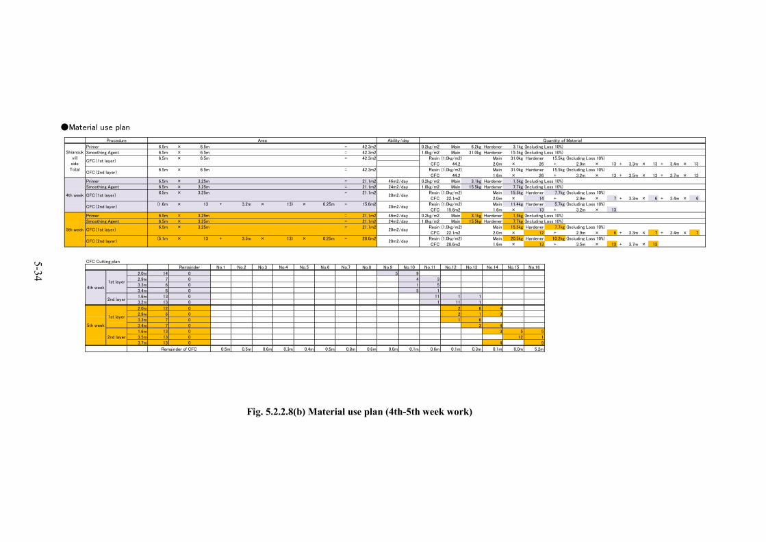
●Material use plan
Primer 6.5m × 6.5m = 42.3m2 0.2kg/m2 Main 6.2kg Hardener 3.1kg6.5m × 6.5m = 42.3m2 1.0kg/m2 Main 31.0kg Hardener 15.5kg6.5m × 6.5m = 42.3m2 Resin Main 31.0kg Hardener 15.5kg
CFC 44.2 2.0m × 26 + 2.9m × 13 + 3.3m × 13 + 3.4m × 136.5m × 6.5m = 42.3m2 Resin Main 31.0kg Hardener 15.5kg
CFC 44.2 1.6m × 26 + 3.2m × 13 + 3.5m × 13 + 3.7m × 13Primer 6.5m × 3.25m = 21.1m2 0.2kg/m2 Main 3.1kg Hardener 1.5kg
6.5m × 3.25m = 21.1m2 1.0kg/m2 Main 15.5kg Hardener 7.7kg6.5m × 3.25m = 21.1m2 Resin Main 15.5kg Hardener 7.7kg
CFC 22.1m2 2.0m × 14 + 2.9m × 7 + 3.3m × 6 + 3.4m × 6(1.6m × 13 + 3.2m × 13) × 0.25m = 15.6m2 Resin Main 11.4kg Hardener 5.7kg
CFC 15.6m2 1.6m × 13 + 3.2m × 13Primer 6.5m × 3.25m = 21.1m2 0.2kg/m2 Main 3.1kg Hardener 1.5kg
6.5m × 3.25m = 21.1m2 1.0kg/m2 Main 15.5kg Hardener 7.7kg6.5m × 3.25m = 21.1m2 Resin Main 15.5kg Hardener 7.7kg
CFC 22.1m2 2.0m × 12 + 2.9m × 6 + 3.3m × 7 + 3.4m × 7(5.1m × 13 + 3.5m × 13) × 0.25m = 28.0m2 Resin Main 20.5kg Hardener 10.2kg
CFC 28.6m2 1.6m × 13 + 3.5m × 13 + 3.7m × 13
CFC Cutting planNo.1 No.2 No.3 No.4 No.5 No.6 No.7 No.8 No.9 No.10 No.11 No.12 No.13 No.14 No.15 No.16
2.0m 14 5 92.9m 7 4 33.3m 6 1 53.4m 6 5 11.6m 13 11 1 13.2m 13 1 11 1
2.0m 12 2 6 42.9m 6 2 1 33.3m 7 1 63.4m 7 3 41.6m 13 3 5 53.5m 13 12 13.7m 13 4 9
0.5m 0.5m 0.6m 0.3m 0.4m 0.5m 0.8m 0.6m 0.0m 0.1m 0.6m 0.1m 0.3m 0.1m 0.0m 5.2m
Procedure Area Ability/day Quantity of Material
ShianoukvillsideTotal
(Including Loss 10%)Smoothing Agent (Including Loss 10%)
CFC(1st layer)(1.0kg/m2) (Including Loss 10%)
CFC(2nd layer)(1.0kg/m2) (Including Loss 10%)
(Including Loss 10%)
CFC(2nd layer) 20m2/day(1.0kg/m2) (Including Loss 10%)
Remainder
Remainder of CFC
4th week
46m2/day (Including Loss 10%)Smoothing Agent 24m2/day (Including Loss 10%)
CFC(1st layer) 20m2/day(1.0kg/m2)
5th week
46m2/day (Including Loss 10%)Smoothing Agent 24m2/day (Including Loss 10%)
CFC(1st layer) 20m2/day(1.0kg/m2) (Including Loss 10%)
CFC(2nd layer) 20m2/day(1.0kg/m2) (Including Loss 10%)
2nd layer00
4th week1st layer
0000
00
5th week
1st layer
0000
2nd layer0
Fig. 5.2.2.8(b) Material use plan (4th-5th week work)

5-35
●Resin mix plan (1st week)Loss 5%Primer
← →
↑ Standard usage weight 0.2kg/m2Including Loss 5%
Area 5.5m2 Area 4.3m2 Area 4.3m2 Area 4.3m2Hight2.5m
Total 1.2kg Total 0.9kg Total 0.9kg Total 0.9kg Main 0.8kg Main 0.6kg Main 0.6kg Main 0.6kg Hardener 0.4kg Hardener 0.3kg Hardener 0.3kg Hardener 0.3kg
↓
Smoothing Agent← →
↑ Standard usage weight 1.0kg/m2Including Loss 5%
Area 5.5m2 Area 4.3m2 Area 4.3m2 Area 4.3m2Hight2.5m
Total 5.8kg Total 4.5kg Total 4.5kg Total 4.5kg Main 4.0kg Main 3.0kg Main 3.0kg Main 3.0kg Hardener 2.0kg Hardener 1.5kg Hardener 1.5kg Hardener 1.5kg
↓
Impregnating Resin (1st Layer)
Standard usage weight 1.0kg/m2Under Application 0.6kg/m2Over Application 0.4kg/m2
Loss 5%
Each cycle (Total 5 cycle)Area
7.3m × 0.5m = 3.7m2
Quantity of MaterialUnder Application
Total 2.3kgMain 1.6kgHardener 0.8kg
Over ApplicationTotal 1.5kgMain 1.2kgHardener 0.6kg
Impregnating Resin (2nd Layer)
Standard usage weight 1.0kg/m2Under Application 0.6kg/m2Over Application 0.4kg/m2
Loss 5%
1st - 4th CycleArea
(1.4m + 2.4m)× 3× 0.25m = 2.9m2
Quantity of MaterialUnder Application
Total 1.8kgMain 1.2kgHardener 0.6kg
Over ApplicationTotal 1.2kgMain 0.8kgHardener 0.4kg
5th CycleArea
(1.4m × 2 +2.4m × 3)
× 0.25m = 2.5m2
Quantity of MaterialUnder Application
Total 1.6kgMain 1.2kgHardener 0.6kg
Over ApplicationTotal 1.1kgMain 0.8kgHardener 0.4kg
Quantity of Material Quantity of Material Quantity of Material Quantity of Material
Total Width 7.3mWidth 2.2m Width 1.7m Width 1.7m
Quantity of MaterialQuantity of MaterialQuantity of MaterialQuantity of Material
Width 1.7m
Width 1.7mWidth 2.2m Width 1.7m Width 1.7mTotal Width 7.3m
500
500
500
500
500
7,300
2,400
1,400
250×29=7,250
250×6=1,500
250×6=1,500
250×6=1,500
250×6=1,500
250×5=1,250
Fig. 5.2.2.9(a) Resin mix plan (1st week work)

5-36
●Resin mix plan (2nd week)Loss 5%Primer
← →
↑ Standard usage weight 0.2kg/m2Including Loss 5%
Area 4.4m2 Area 3.4m2 Area 3.4m2 Area 3.4m2Hight2.0m
Total 0.9kg Total 0.7kg Total 0.7kg Total 0.7kg Main 0.8kg Main 0.6kg Main 0.6kg Main 0.6kg Hardener 0.4kg Hardener 0.3kg Hardener 0.3kg Hardener 0.3kg
↓
Smoothing Agent← →
↑ Standard usage weight 1.0kg/m2Including Loss 5%
Area 4.4m2 Area 3.4m2 Area 3.4m2 Area 3.4m2Hight2.0m
Total 4.6kg Total 3.6kg Total 3.6kg Total 3.6kg Main 3.2kg Main 2.4kg Main 2.4kg Main 2.4kg Hardener 1.6kg Hardener 1.2kg Hardener 1.2kg Hardener 1.2kg
↓
Impregnating Resin (1st Layer)
Standard usage weight 1.0kg/m2Under Application 0.6kg/m2Over Application 0.4kg/m2
Loss 5%
Each cycle (Total 4 cycle)Area
7.3m × 0.5m = 3.7m2
Quantity of MaterialUnder Application
Total 2.3kgMain 1.6kgHardener 0.8kg
Over ApplicationTotal 1.5kgMain 1.2kgHardener 0.6kg
Impregnating Resin (2nd Layer)
Standard usage weight 1.0kg/m2Under Application 0.6kg/m2Over Application 0.4kg/m2
Loss 5%
1st - 4th CycleArea
(2.5m + 2.4m)× 3× 0.25m = 3.7m2
Quantity of MaterialUnder Application
Total 2.3kgMain 1.6kgHardener 0.8kg
Over ApplicationTotal 1.5kgMain 1.2kgHardener 0.6kg
5th CycleArea
(2.5m × 3 +2.4m × 2)
× 0.25m = 3.1m2
Quantity of MaterialUnder Application
Total 1.9kgMain 1.4kgHardener 0.7kg
Over ApplicationTotal 1.3kgMain 1.0kgHardener 0.5kg
Quantity of Material Quantity of Material Quantity of Material Quantity of Material
Total Width 7.3m
Total Width 7.3mWidth 2.2m Width 1.7m Width 1.7m Width 1.7m
Width 1.7m Width 1.7m
Quantity of Material Quantity of Material Quantity of Material Quantity of Material
Width 2.2m Width 1.7m
500
500
500
500
7,300
2,400
1,000
250×29=7,250
250×6=1,500
250×6=1,500
250×6=1,500
250×6=1,500
250×5=1,250
2,500
Fig. 5.2.2.9(b) Resin mix plan (2nd week work)

5-37
●Resin mix plan (3rd week)Loss 5%Primer
← →
↑ Standard usage weight 0.2kg/m2Including Loss 5%
Area 5.5m2 Area 4.3m2 Area 4.3m2 Area 4.3m2Hight2.5m
Total 1.2kg Total 0.9kg Total 0.9kg Total 0.9kg Main 0.8kg Main 0.6kg Main 0.6kg Main 0.6kg Hardener 0.4kg Hardener 0.3kg Hardener 0.3kg Hardener 0.3kg
↓
Smoothing Agent← →
↑ Standard usage weight 1.0kg/m2Including Loss 5%
Area 5.5m2 Area 4.3m2 Area 4.3m2 Area 4.3m2Hight2.5m
Total 5.8kg Total 4.5kg Total 4.5kg Total 4.5kg Main 4.0kg Main 3.0kg Main 3.0kg Main 3.0kg Hardener 2.0kg Hardener 1.5kg Hardener 1.5kg Hardener 1.5kg
↓
Impregnating Resin (1st Layer)
Standard usage weight 1.0kg/m2Under Application 0.6kg/m2Over Application 0.4kg/m2
Loss 5%
Each cycle (Total 5 cycle)Area
7.3m × 0.5m = 3.7m2
Quantity of MaterialUnder Application
Total 2.3kgMain 1.6kgHardener 0.8kg
Over ApplicationTotal 1.5kgMain 1.2kgHardener 0.6kg
Impregnating Resin (2nd Layer)
Standard usage weight 1.0kg/m2Under Application 0.6kg/m2Over Application 0.4kg/m2
Loss 5%
1st - 4th CycleArea
(2.5m + 3.6m)× 3× 0.25m = 4.6m2
Quantity of MaterialUnder Application
Total 2.9kgMain 2.0kgHardener 1.0kg
Over ApplicationTotal 1.9kgMain 1.4kgHardener 0.7kg
5th CycleArea
(2.5m × 3 +3.6m × 2)
× 0.25m = 3.7m2
Quantity of MaterialUnder Application
Total 2.3kgMain 1.6kgHardener 0.8kg
Over ApplicationTotal 1.5kgMain 1.2kgHardener 0.6kg
Quantity of Material Quantity of Material Quantity of Material Quantity of Material
Total Width 7.3m
Total Width 7.3mWidth 2.2m Width 1.7m Width 1.7m Width 1.7m
Width 1.7m Width 1.7m
Quantity of Material Quantity of Material Quantity of Material Quantity of Material
Width 2.2m Width 1.7m
500
500
500
500
500
7,300
2,500
200
250×29=7,250
250×6=1,500
250×6=1,500
250×6=1,500
250×6=1,500
250×5=1,250
2,5001,300
Fig. 5.2.2.9(c) Resin mix plan (3rd week work)

5-38
●Resin mix plan (4th week)Loss 5%Primer
← →
↑ Standard usage weight 0.2kg/m2Including Loss 5%
Area 5.2m2 Area 5.2m2 Area 5.2m2 Area 5.5m2Hight3.25m
Total 1.1kg Total 1.1kg Total 1.1kg Total 1.2kg Main 0.8kg Main 0.8kg Main 0.8kg Main 0.8kg Hardener 0.4kg Hardener 0.4kg Hardener 0.4kg Hardener 0.4kg
↓
Smoothing Agent← →
↑ Standard usage weight 1.0kg/m2Including Loss 5%
Area 5.2m2 Area 5.2m2 Area 5.2m2 Area 5.5m2Hight3.25m
Total 5.5kg Total 5.5kg Total 5.5kg Total 5.8kg Main 3.8kg Main 3.8kg Main 3.8kg Main 4.0kg Hardener 1.9kg Hardener 1.9kg Hardener 1.9kg Hardener 2.0kg
↓
Impregnating Resin (1st Layer)
Standard usage weight 1.0kg/m2Under Application 0.6kg/m2Over Application 0.4kg/m2
Loss 5%
1-5th cycleArea
6.5m × 0.50m = 3.3m2
Quantity of MaterialUnder Application
Total 2.0kgMain 1.4kgHardener 0.7kg
Over ApplicationTotal 1.4kgMain 1.0kgHardener 0.5kg
6th cycleArea
6.5m × 0.75m = 4.9m2
Quantity of MaterialUnder Application
Total 3.1kgMain 2.2kgHardener 1.1kg
Over ApplicationTotal 2.0kgMain 1.4kgHardener 0.7kg
Impregnating Resin (2nd Layer)
Standard usage weight 1.0kg/m2Under Application 0.6kg/m2Over Application 0.4kg/m2
Loss 5%
1st - 3rd CycleArea
(1.6m + 3.2m)× 3× 0.25m = 3.6m2
Quantity of MaterialUnder Application
Total 2.3kgMain 1.6kgHardener 0.8kg
Over ApplicationTotal 1.5kgMain 1.2kgHardener 0.6kg
4th CycleArea
(1.6m + 3.2m)× 4× 0.25m = 4.8m2
Quantity of MaterialUnder Application
Total 3.0kgMain 2.2kgHardener 1.1kg
Over ApplicationTotal 2.0kgMain 1.4kgHardener 0.7kg
Quantity of Material Quantity of Material Quantity of Material Quantity of Material
Total Width 6.5mWidth 1.6m Width 1.6m Width 1.6m Width 1.7m
Quantity of Material Quantity of Material Quantity of Material Quantity of Material
Total Width 6.5mWidth 1.6m Width 1.6m Width 1.6m Width 1.7m
500
500
500
500
500
6,500
750
3,200
1,600
250×26=6,500
250×8=2,000
250×6=1,500
250×6=1,500
250×6=1,500
Fig. 5.2.2.9(d) Resin mix plan (4th week work)

5-39
●Resin mix plan (5th week)Loss 5%Primer
← →
↑ Standard usage weight 0.2kg/m2Including Loss 5%
Area 5.2m2 Area 5.2m2 Area 5.2m2 Area 5.5m2Hight3.25m
Total 1.1kg Total 1.1kg Total 1.1kg Total 1.2kg Main 0.8kg Main 0.8kg Main 0.8kg Main 0.8kg Hardener 0.4kg Hardener 0.4kg Hardener 0.4kg Hardener 0.4kg
↓
Smoothing Agent← →
↑ Standard usage weight 1.0kg/m2Including Loss 5%
Area 5.2m2 Area 5.2m2 Area 5.2m2 Area 5.5m2Hight3.25m
Total 5.5kg Total 5.5kg Total 5.5kg Total 5.8kg Main 3.8kg Main 3.8kg Main 3.8kg Main 4.0kg Hardener 1.9kg Hardener 1.9kg Hardener 1.9kg Hardener 2.0kg
↓
Impregnating Resin (1st Layer)
Standard usage weight 1.0kg/m2Under Application 0.6kg/m2Over Application 0.4kg/m2
Loss 5%
1-5th cycleArea
6.5m × 0.50m = 3.3m2
Quantity of MaterialUnder Application
Total 2.0kgMain 1.4kgHardener 0.7kg
Over ApplicationTotal 1.4kgMain 1.0kgHardener 0.5kg
6th cycleArea
6.5m × 0.75m = 4.9m2
Quantity of MaterialUnder Application
Total 3.1kgMain 2.2kgHardener 1.1kg
Over ApplicationTotal 2.0kgMain 1.4kgHardener 0.7kg
Impregnating Resin (2nd Layer)
Standard usage weight 1.0kg/m2Under Application 0.6kg/m2Over Application 0.4kg/m2
Loss 5%
1st - 4th CycleArea
(3.5m + 5.1m)× 2× 0.25m = 4.3m2
Quantity of MaterialUnder Application
Total 2.7kgMain 2.0kgHardener 1.0kg
Over ApplicationTotal 1.8kgMain 1.4kgHardener 0.7kg
5th CycleArea
(3.5m × 3+ 5.1m × 2)
× 0.25m = 5.2m2
Quantity of MaterialUnder Application
Total 3.3kgMain 2.2kgHardener 1.1kg
Over ApplicationTotal 2.2kgMain 1.6kgHardener 0.8kg
6th CycleArea
(3.5m × 2+ 5.1m × 3)
× 0.25m = 5.6m2
Quantity of MaterialUnder Application
Total 3.5kgMain 2.4kgHardener 1.2kg
Over ApplicationTotal 2.3kgMain 1.6kgHardener 0.8kg
Quantity of Material Quantity of Material Quantity of Material Quantity of Material
Total Width 6.5mWidth 1.6m Width 1.6m Width 1.6m Width 1.7m
Quantity of Material Quantity of Material Quantity of Material Quantity of Material
Total Width 6.5mWidth 1.6m Width 1.6m Width 1.6m Width 1.7m
500
500
500
500
500
6,500
750
5,100
3,500
250×26=6,500
250×5=1,250
250×4=1,000
250×4=1,000
250×4=1,000
250×4=1,000
250×5=1,250
Fig. 5.2.2.9(e) Resin mix plan (5th week work)
5-40
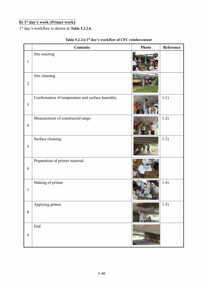
b) 1st day’s work (Primer work) 1st day’s workflow is shown in Table 5.2.2.6.
Contents Photo Reference
1
Site meeting
2
Site cleaning
3
Confirmation of temperature and surface humidity 1-1)
4
Measurement of constructed range 1-2)
5
Surface cleaning 1-3)
6
Preparation of primer material
7
Making of primer 1-4)
8
Applying primer 1-5)
9
End
Table 5.2.2.6 1st day’s workflow of CFC reinforcement

5-41
1-1) Confirmation of temperature and surface humidity To measure moisture of the concrete surface (Photo 5.2.2.10) and if it is more than 8%, dry the concrete surface or postpone primer application work. It is better to measure about 5 point per 1 span. 1-2) Measurement of constructed range The measurement of constructed range is carried out to mark it (Photo 5.2.2.11). 1-3) Surface cleaning By using polishing sheet or disk grinder, the dust and dirt is removed from the concrete surface (Photo 5.2.2.12).
Photo 5.2.2.10 To measure moisture of the concrete surface
Photo 5.2.2.11 Measurement of constructed range

5-42
1-4) Making of primer Primer material consists of ‘Main material’ and ‘Hardener’ (Photo 5.2.2.13). Defined amounts of ‘Main material’ and ‘Hardener’ are weighed (Photo 5.2.2.14) and mixed to uniform texture (about 3 minutes) (Photo 5.2.2.15).
(Mixing Ratio (Weight); Main material: Hardener = 2:1) After the materials are mixed, the material starts to become hard. It is necessary to mix well and use the material within 30 min. after starting mixing time (30 degree Celsius). Therefore, the mixing time (about 3 min.) and using time (30 min.) was measured by using a stopwatch.
Photo 5.2.2.13 Primer material
Main material Hardener
2 : 1 Mixing Ratio (Weight)
Photo 5.2.2.12 Surface cleaning

5-43
Photo 5.2.2.14 Weighing material (Primer material)
Photo 5.2.2.15 Mixing material (Primer material)
Quantity of primer material used 0.9kg/1 time (Main: Hardener = 0.6:0.3) 0.21kg/m2 (Main: Hardener = 1.4:0.7) (Depend on the worker’s skill)

5-44
1-5) Applying primer Uniform amount of primer is applied on the concrete surface by using an application roller or a brush (Fig. 5.2.2.10, Photo 5.2.2.16). .
Primer
Application roller
Photo 5.2.2.16 Applying prime
Fig. 5.2.2.10 Applying prime
Application roller
Brush

5-45
c) 2nd day’s work (Smoothing agent work) 2nd day’s workflow is shown in Table 5.2.2.7.
Contents Photo Reference
1 Site meeting
2 Site cleaning
3 Confirmation of temperature and surface humidity
4 Confirmation of primer surface flatness
2-1)
5 Preparation of smoothing agent material
6 Making of smoothing agent
2-2)
7 Applying smoothing agent
2-3)
8 End
Table 5.2.2.7 2nd day’s workflow of CFC reinforcement
5-46
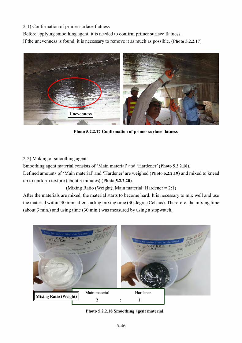
2-1) Confirmation of primer surface flatness Before applying smoothing agent, it is needed to confirm primer surface flatness. If the unevenness is found, it is necessary to remove it as much as possible. (Photo 5.2.2.17) 2-2) Making of smoothing agent Smoothing agent material consists of ‘Main material’ and ‘Hardener’ (Photo 5.2.2.18). Defined amounts of ‘Main material’ and ‘Hardener’ are weighed (Photo 5.2.2.19) and mixed to knead up to uniform texture (about 3 minutes) (Photo 5.2.2.20).
(Mixing Ratio (Weight); Main material: Hardener = 2:1) After the materials are mixed, the material starts to become hard. It is necessary to mix well and use the material within 30 min. after starting mixing time (30 degree Celsius). Therefore, the mixing time (about 3 min.) and using time (30 min.) was measured by using a stopwatch. Photo 5.2.2.18 Smoothing agent material
Main material Hardener
2 : 1 Mixing Ratio (Weight)
Photo 5.2.2.17 Confirmation of primer surface flatness
Unevenness

5-47
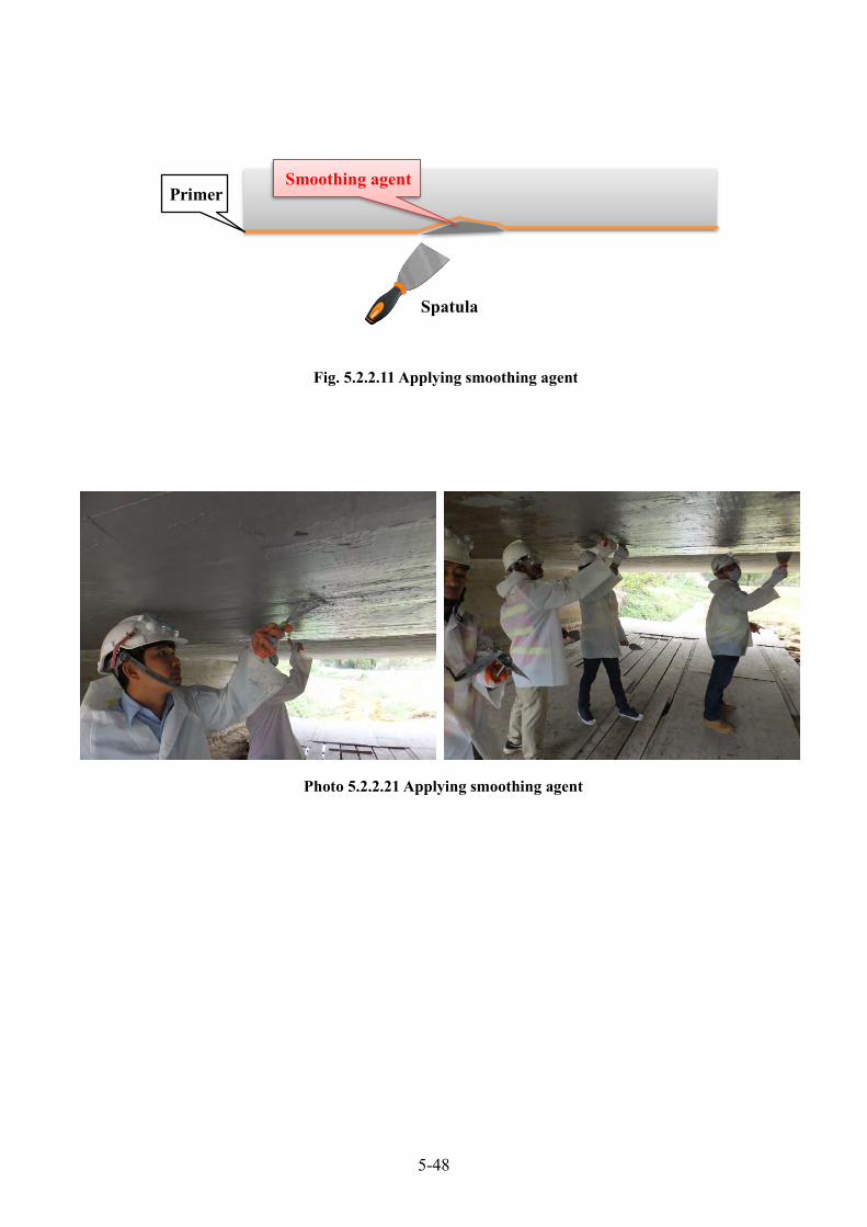
2-3) Applying smoothing agent Smoothing agent is applied on the concrete surface flatten (less than 1mm difference in level) using by spatula or a trowel (Fig. 5.2.2.11, Photo 5.2.2.21) because surface difference in level or edge of the corner causes bad bonding and break of carbon fiber. At first, hardening of the primer is confirmed before smoothing agent application. After the smoothing agent application work is finished, an interval of more than 24 hours is necessary for smoothing agent to become hard (30 degree Celsius).
Photo 5.2.2.19 Weighing material (Smoothing agent material)
Photo 5.2.2.20 Mixing material (Smoothing agent material)
Quantity of smoothing agent material used 3kg/1 time (Main : Hardener = 2:1) , 1.5kg/m2 (Main : Hardener = 1:0.5) (Depend on the worker’s skill)
5-48
Primer Smoothing agent
Spatula
Fig. 5.2.2.11 Applying smoothing agent
Photo 5.2.2.21 Applying smoothing agent

5-49
c) 3rd day’s work (1st CFC layer work) 3rd day’s workflow is shown in Table 5.2.2.8.
Contents Photo Reference
1 Site meeting
2 Site cleaning
3 Confirmation of temperature and surface humidity
4 Confirmation of smoothing agent surface flatness
3-1)
5 Measurement of CFC construction range
3-2)
6 Cutting CFC
3-3)
7 Preparation of impregnating resin material
8 Making of impregnating resin material
3-4)
9 Applying 1st impregnating resin
3-5)
Table 5.2.2.8(a) 3rd day’s workflow of CFC reinforcement

5-50
Contents Photo Reference
10 Setting CFC
3-6)
11 Pushing out air bubbles by paddle roller
3-7)
12 Applying 1st impregnating resin (once again)
3-8)
13 Applying 2nd impregnating resin (After 20 min of ‘12’ work)
3-9)
14 End
Table 5.2.2.8(b) 3rd day’s workflow of CFC reinforcement

5-51
3-1) Confirmation of smoothing agent surface flatness Before applying impregnating resin, it is needed to confirm smoothing agent surface flatness. If the unevenness is found, it is necessary to remove it by using polishing sheet or disk grinder as much as possible. (Photo 5.2.2.22) 3-2) Measurement of CFC construction range The measurement of CFC construction range is carried out to mark it (Photo 5.2.2.23).
Photo 5.2.2.22 Confirmation of smoothing agent surface flatness
Unevenness
Photo 5.2.2.23 Measurement of CFC construction range

5-52
3-3) Cutting CFC CFC is cut at a right angle with fiber direction, according to the arrangement plan < example) Fig. 5.2.2.7(a)-(e) > by scissors or cutter (Photo 5.2.2.24). CFC’s length should be including splice length. 3-4) Making of impregnating resin material Impregnating resin material consists of ‘Main material’ and ‘Hardener’ (Photo 5.2.2.25). Defined amounts of ‘Main material’ and ‘Hardener’ are weighed (Photo 5.2.2.26) and mixed to uniform texture by using agitator (about 3 minutes) (Photo 5.2.2.27).
(Mixing Ratio (Weight); Main material: Hardener = 2:1)
Photo 5.2.2.24 Cutting CFC
Photo 5.2.2.25 Impregnating resin material
Main material Hardener
2 : 1 Mixing Ratio (Weight)

5-53
3-5) Applying 1st impregnating resin Impregnating resin is applied by using an application roller. (Fig. 5.2.2.12, Photo 5.2.2.28). Short of impregnating resin causes lack of strength. Therefore impregnating resin must be applied sufficient amount. After the applying 1st impregnating resin work is finished, an interval of less than 24 hours is necessary to become hard (30 degree Celsius) until next work.
Photo 5.2.2.26 Weighing material (Impregnating resin material)
Photo 5.2.2.27 Mixing material (Impregnating resin)
Quantity of impregnating resin material used 2.4kg/1 time (Main : Hardener = 1.6:0.8) , 1.2kg/m2 (Main : Hardener = 0.8:0.4) (Depend on the worker’s skill)
Agitator

5-54
3-6) Setting CFC CFC arrangement plan (Including splice length.) should be prepared before site work (Fig. 5.2.2.7(a)-(e)). And CFC is set on the under applying impregnating resin along the marking plan (Photo 5.2.2.29). Photo 5.2.2.29 Setting CFC
Primer Smoothing agent
Impregnating resin (Under application)
Application roller
Fig. 5.2.2.12 Applying 1st impregnating resin
Photo 5.2.2.28 Applying 1st impregnating resin
Applied sufficient amount

5-55
3-7) Pushing out air bubbles by paddle roller CFC should be pushed by using a paddle roller in order to push out air bubbles into CFC. (Fig. 5.2.2.13, Photo 5.2.2.30) At that time, the impregnation roller is rolled along the fiber direction. Pushing out air bubbles work should be finished less than 24 hours from setting CFC to become hard (30 degree Celsius).
Primer Smoothing agent
Impregnating resin (Under application) CFC
Paddle roller
Photo 5.2.2.30 Pushing out air bubbles by paddle roller
Fig. 5.2.2.13 Pushing out air bubbles by paddle roller

5-56
If CFC is impregnated by impregnating resin, color of glass fiber in CFC turns to resin color. (Photo 5.2.2.31) So, please check glass fiber color after pushing out air bubbles. 3-8) Applying 1st impregnating resin (once again) The impregnating resin is applied again for applied sufficient amount (Photo 5.2.2.32).
Photo 5.2.2.31 Turning glass fiber color
Glass fiber: White Color
Impregnating resin: Green Color
(a) Before pushing out air by paddle roller (b) After pushing out air by paddle roller
Glass fiber: Green Color
Photo 5.2.2.32 Applying 1st impregnating resin (once again)

5-57
3-9) Applying 2nd impregnating resin (After 20 min of ‘3-8)’ work) Impregnating resin material of 2nd layer consists of same to that of 1st layer. <Reference: 3-5) > Therefore defined amounts of ‘Main material’ and ‘Hardener’ are same weighed. 2nd impregnating resin is applied by using an application roller. (Fig. 5.2.2.14, Photo 5.2.2.33). Be careful not to move the CRC when applying. And check the usage limit time of 2nd impregnating resin. After the 2nd impregnating resin application work is finished, an interval of more than 24 hours is necessary for 2nd impregnating resin to become hard (30 degree Celsius).
Primer Smoothing agent
Impregnating resin (Under application)
Impregnating resin (Over application)
CFC
Application roller
Fig. 5.2.2.14 Applying 2nd impregnating resin
Photo 5.2.2.33 Applying 2nd impregnating resin

5-58
d) 4th day’s work (2nd CFC layer work) 4th day’s workflow is shown in Table 5.2.2.9.
Contents Photo Reference
1 Site meeting
2 Site cleaning
3 Confirmation of temperature and surface humidity
4 Confirmation of pushing out air bubbles
4-1)
5 Repairing after completely cured impregnating resin (If necessary from 4 work)
4-2)
6 Confirmation of impregnating resin surface flatness
4-3)
7 Measurement of CFC construction range
4-4)
8 Cutting CFC
9 Preparation of impregnating resin material
Table 5.2.2.9(a) 4th day’s workflow of CFC reinforcement

5-59
Contents Photo Reference
10 Making of impregnating resin material
4-5)
11 Applying 1st impregnating resin
4-6)
12 Setting CFC
4-7)
13 Pushing out air bubbles
4-8)
14 Applying 1st impregnating resin (once again)
15 Applying 2nd impregnating resin (After 20 min of ‘14’ work)
4-9)
16 End
Table 5.2.2.9(b) 4th day’s workflow of CFC reinforcement

5-60
4-1) Confirmation of pushing out air bubbles Before applying impregnating resin of 2nd CFC layer, it is needed to confirm of pushing out air bubbles of 1st CFC layer (Photo 5.2.2.34). If the peeling is found, it is necessary to repair of this part < Reference: 4-2) >. 4-2) Repairing after completely cured impregnating resin If the peeling is found from 4-1) work, it is necessary to repair this part (Photo 5.2.2.35). 1) The failure part is removed carefully by using disk grinder. 2) It is backfilled by impregnation resin. 3) CFC patch is overlapped with impregnation resin.
Photo 5.2.2.34 Confirmation of pushing out air bubbles
Peeling (It is necessary to repair of this part)
Photo 5.2.2.35 Repairing after completely cured impregnating resin
Peeling

5-61
4-3) Confirmation of impregnating resin surface flatness It is needed to confirm impregnating resin surface flatness. If the unevenness is found, it is necessary to remove it by using polishing sheet or disk grinder as much as possible. (Photo 5.2.2.36) 4-4) Measurement of CFC construction range The measurement of CFC construction range is carried out to mark it (Photo 5.2.2.37). 4-5) Making of impregnating resin material Impregnating resin material is prepared < Reference: 3-4) >. 4-6) Applying 1st impregnating resin Impregnating resin is applied by using an application roller. < Reference: 3-5) >.
Photo 5.2.2.36 Confirmation of impregnating resin surface flatness
Photo 5.2.2.37 Measurement of CFC construction range

5-62
4-7) Setting CFC CFC arrangement plan (Including splice length.) should be prepared before site work < Reference: 3-6) >. 4-8) Pushing out air bubbles CFC should be pushed by using a paddle roller in order to push out air bubbles into CFC < Reference: 3-7) >. 4-9) Applying 2nd impregnating resin (After 20 min of ‘14’ work) Impregnating resin material of 2nd layer consists of same to that of 1st layer < Reference: 3-9) >. The completion status of this repair method is shown to Photo 5.2.2.38.
Photo 5.2.2.38 Completion

5-63
(d) Remarks If the peeling of CFC is found out after completion of reinforcement work, it should be repaired partially. . a) Repairing at the initial curing (Fig 5.2.2.15) 1) It is cut several locations into the fiber direction on the surface by using box cutter. 2) ‘Impregnating resin’ is applied from the surface by using a brush or spatula. b) Repairing after completely cured (Fig 5.2.2.16) If the peeling of CFC is found out after completely cured, it should be cut open and patched. 1) The failure part is removed carefully. 2) It is backfilled by the smoothing agent. 3) CFC patch is overlapped with impregnation resin. (CFC patch is same number of layer as the
original CFC)
Fig 5.2.2.15 Repairing at the initial curing
Fig 5.2.2.16 Repairing at the initial curing

5-64
Please pay attention to electric shock because CFC conducts electricity (Fig 5.2.2.17). And if there is electric wire near work space, it should be covered and sealed.
Fig 5.2.2.17 Patching repair method

5-65
C-3 Corrosion of reinforcement in concrete pier column (a) Conditions Concrete pieces were damaged to exfoliate from the column of rigid frame (Photo 5.2.3.1). Through the hammer-tapping off the damaged concrete, corrosion on the RE-bars and rust float were observed along the hoop (Photo 5.2.3.2 and Photo 5.2.3.3).
(b) Possible Causes The pier columns were made much higher than other columns to cross over the elevated railroad. It is speculated, in such a height, that conditions caused improper concrete placement, coarse aggregate segregation, and insufficient compaction. Corrosion on RE-bars initiated because of the existence of honeycomb in concrete, insufficient thickness of covering concrete where cracks generate, ingress of rainwater. Such corrosion is understood to have caused the exfoliation and dropping of concrete. In heavily exfoliated area, the honeycomb repairs with mortar had been experienced. Some of these repair patches caused exfoliation probably due to difference in material properties or vibration. (c) Outline of repair The honeycomb in concrete was completely chipped off. The chipped areas were covered by epoxy putty sealant with grout infection (Photo 5.2.3.4 and Photo 5.2.3.5).
Photo 5.2.3.1 General view of damaged part
Photo 5.2.3.2 Concrete flake-off Photo 5.2.3.3 Exposed RE-bars and
concrete flake-off

5-66
To prevent the concrete exfoliation, steel plates (4.5mm thick) were affixed on the concrete surface (Fig. 5.2.3.1, Photo 5.2.3.6).
Photo 5.2.3.4 Repair by putty sealant
Photo 5.2.3.5 Grout injection hole provided
Photo 5.2.3.6 Steel plates affixed
Fig. 5.2.3.1 Steel plates affixed
5-67
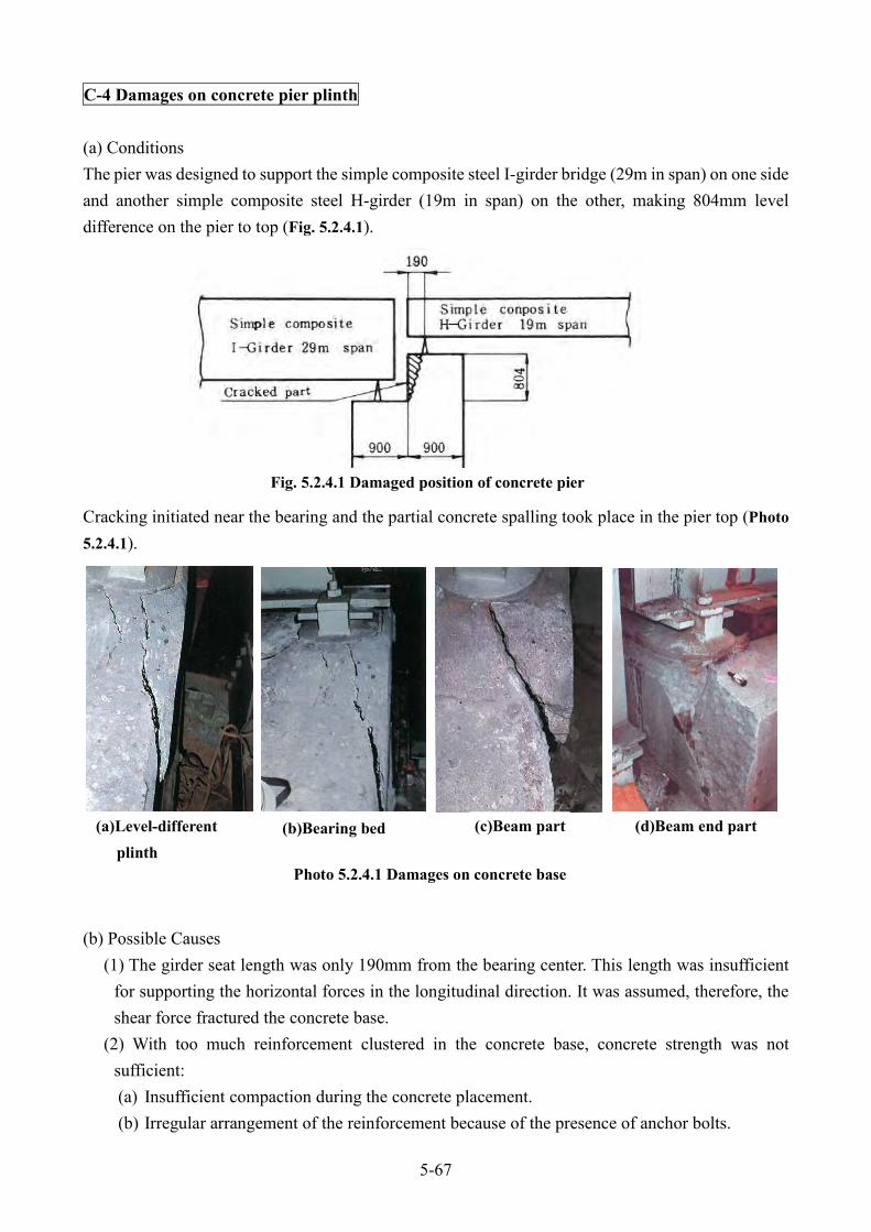
C-4 Damages on concrete pier plinth
(a) Conditions The pier was designed to support the simple composite steel I-girder bridge (29m in span) on one side and another simple composite steel H-girder (19m in span) on the other, making 804mm level difference on the pier to top (Fig. 5.2.4.1).
Cracking initiated near the bearing and the partial concrete spalling took place in the pier top (Photo 5.2.4.1).
(b) Possible Causes (1) The girder seat length was only 190mm from the bearing center. This length was insufficient
for supporting the horizontal forces in the longitudinal direction. It was assumed, therefore, the shear force fractured the concrete base.
(2) With too much reinforcement clustered in the concrete base, concrete strength was not sufficient: (a) Insufficient compaction during the concrete placement. (b) Irregular arrangement of the reinforcement because of the presence of anchor bolts.
Fig. 5.2.4.1 Damaged position of concrete pier
Photo 5.2.4.1 Damages on concrete base
(a)Level-different plinth
(b)Bearing bed (c)Beam part (d)Beam end part

5-68
(3) The current design standard requires the seat length not to be less than 200mm for the staggered beam (Fig.5.2.4.2). In this condition, the staggered beam exhibits strong enough against the shearing force.
(c) Outline of repairs Fig.5.2.4.3 shows the repairing method of the damaged part of concrete base, with attaching steel plate. The steel plate serves dual purpose, reinforcement and form for concrete. The procedures taken in this repair is as follows.
(1) Install L-shape steel member to the girder web at the jacking position, reinforcing the temporary support for the bearing (Fig. 5.2.4.4).
(2) Install jacks (two sets of 100 ton hydraulic jacks) as temporary support.
Fig. 5.2.4.4 Steel plate for reinforcement of pier plinth
Fig. 5.2.4.2 Required seat length
Fig. 5.2.4.3 Required bed edge distance

5-69
(3) Jack up (Photo 5.2.4.2). (4) Remove the damaged concrete part (Photo 5.2.4.3).
(5) Place hole-in anchors (Fig.5.2.4.4) (6) Arrange reinforcement and install steel
plate (Photo 5.3.4.4) (7) Seal around the steel plate and the hole in
anchors. (8) Place prepacked concrete. Epoxy resin was
injected as bonding material from the pier top after filing up the aggregate (Photo 5.2.4.5).
(9) Curing. (10) Adjust the bearing position (height and level). (11) Place mortar for bearing. (12) Curing. (13) Paint of the face plate (Photo 5.2.4.6).
Photo 5.2.4.2 Temporary support by jack up Photo 5.2.4.3 Damaged concrete chipped off
Photo 5.2.4.4 Steel plate being mounted
Photo 5.2.4.5 Poring epoxy resin Photo 5.2.4.6 Reinforcing steel plate painted

5-70
C-5 Cavity in the lower flange
(a) Condition PC girder (Post-tensioned or Pre-stressed Concrete) was found to have cavity at a mid-span part in a lower flange (Photo 5.2.5.1). The hammer-tapping around the cavity broke off the concrete cover in about 30cm×100cm area exposed sheaths (Photo 5.2.5.2).
(b) Possible Causes The damaged area and its surroundings had concrete paste. The possible cause was understood as insufficient compaction of concrete and lack of cover concrete thickness for the sheaths.
(c) Outline of repairs Repair was carried out first by hammering and removing the damaged concrete, then by placing a putty sealant, and lastly by filling the cavity with epoxy resin mortar (Photo 5.2.5.3).
(d) Remarks The repair was performed without traffic suspension, and it was structurally doubtful if such repair was applied for pre-stressed concrete. In this case, insufficient fabrication workmanship of the main girder caused the defect. From now on, therefore, it is required to be much more careful for the sheaths arrangement and concrete quality control, especially of compaction, of the girder fabrication.
Photo 5.2.5.1 Cavity in flange Photo 5.2.5.2 Condition after
hammer-tapping
Photo 5.2.5.3 Damage repair (a)Epoxy resin applied for the repair (b)Repair working

5-71
C-6 Water leakage from the lower flange
(a) Conditions Efflorescence flowed out from the lower flange at a mid-span of the posttensioned pre-stressed concrete girder, its deposit hanging like icicles from the lower flange (Photo 5.2.6.1).
(b) Possible Causes (1) In search of cause, from the road surface fluorescent paint material was poured over the
damaged area. The paint flowed out from the damaged position of the lower flange of the girder, evidencing that the rainwater of road surface was penetrating into the girder.
(2) The leakage was located about 8.5m to the mid-span from the girder end (Fig. 5.2.6.1). It was judged it originated from C3 and C4 sheaths (Fig. 5.2.6.2).
(3) To confirm the grouting workmanship, soffit concrete portion was removed (Fig. 5.2.6.2). The sheath was easily broken when it was hammered.
(4) The site investigation revealed corrosion of PC steel wire and seepage of a small amount of water from the C4 sheath. It was assumed the rainwater came in from the girder end, penetrated the C4 sheath, and came out from the damage position.
Photo 5.2.6.1 Deposit of free hanging like icicles
Fig. 5.2.6.1 Side view of main girder
Fig. 5.2.6.2 Chipped part and arrangement of sheaths

5-72
(5) The cause for the damage was insufficient grouting work of sheath at the construction stage and subsequent rainwater.
(c) Outline of repairs The sheath location was identified by means of ultrasonic wave transmitted across the main girder section in the thickness direction. To confirm of the sheath position in relation with the girder size, holes were drilled outside at the sheath position. Grout filling was carried out through the holes, starting from the mid-span, until the grouting material flowed out from the inspection holes. The repair was complete with the resin filling of inspection holes and the restoration of the gauged girder with resin.
(d) Remarks (1) At the end of pre-stressed concrete girder, a number of PC steel cables were bent up and
anchored on the deck surface (Fig. 5.2.6.1). With an insufficient grouting in the sheath, the rainwater came in through the pavement, entered the sheath from the anchoring position, and moved to the mid-span parts where it stayed.
(2) The mid-span was crowded with many PC cables, and the rainwater in the sheath would have damaged the lower flange concrete. (Fig. 5.2.6.2)
(3) A very careful girder fabrication, especially careful concrete placing, is required because the lower flange is not ideal for concrete placement because of:
a. Difficulty to obtain uniform quality concrete. b. Difficulty to obtain good distribution of coarse aggregate.
(4) The repair in the early state is required because in the meantime the long run PC steel cables would eventually be broken due to corrosion.
(5) It was recommended to develop and establish a method to diagnose the soundness of PC cables.
Photo 5.2.6.2 Steel wire exposed by hammering Photo 5.2.6.3 Lower flange after chipping-off

5-73
C-7 Cracking damage on slab (a) Conditions Honeycomb (or carapace shell) patterned cracking, 0.1mm-0.3mm, grew in the soffit of slab concrete (Photo 5.2.7.1 and Fig. 5.2.7.1). The cracks clustering area exhibited square pattern. From measurement, the cracking density was 7.5mm2-10mm2 (Table 5.2.7.1).
Photo 5.2.7.1 Crack on the slab (a) A-4 panel damage (b) B-5 panel damage
Fig. 5.2.7.1 Honeycomb patterned cracking
(a) A-4 panel damage (b) B-4 ,B-5.C-5 panel damage

5-74
(b) Outline of repair According to the criteria of slab damage, the slab needs to be repaired through the reinforcement method to restore its function, and if possible enhancement of rigidity was preferred. The reinforcement method was as follows. The most suitable repair from method must be selected.
1) Epoxy Bonded Steel Plate Method Set steel plate adhered on the slab underside surface with synthetic resin adhesive to increase bending strength. Adoption of the method was decided as: - Works on the roadway with traffic control must be restricted to ensure free and smooth traffic. - Concrete pieces must be prevented from falling on to the roads at grade.
2) Additional Concrete Method Place additional concrete on the slab surface to increase the slab thickness and to gain further shearing strength.
3) Girder Addition Method
Supply additional girder to the slab underside to shorten the span. 4) Reconstruction Method
Remove the damaged slab and install new slab cast in place. This is the most reliable repair method.
‘Epoxy Bonded Steel Plate Method’ which is most commonly adopted is shown in Fig. 5.2.7.2. The deflection measurement and the load test proved increased bending rigidity of slab repaired by this method. However, steel plate adhered under the entire slab surface makes it unavailable to evaluate whether damages in the slab is progressive after the repair.
B-4 B-5 C-5 A-4
Density
(mm2)
Ratio
(%)
Density
(mm2)
Ratio
(%)
Density
(mm2)
Ratio
(%)
Density
(mm2)
Ratio
(%)
Bridge axial direction 4.63 47.4 5.12 47.7 3.54 45.0 2.34 31.2
Orthogonal to bridge direction 5.13 52.6 5.62 52.3 4.32 55.0 5.26 68.3
Total 9.76 100.0 10.74 100.0 7.85 100.0 7.50 100.0
Table 5.2.7.1 Result of cracking density measurement

5-75
Fig. 5.2.7.2 Procedure of ‘Epoxy bonded steel plate method’
5-76
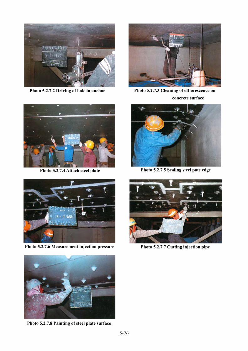
Photo 5.2.7.2 Driving of hole in anchor Photo 5.2.7.3 Cleaning of efflorescence on concrete surface
Photo 5.2.7.4 Attach steel plate Photo 5.2.7.5 Sealing steel pate edge
Photo 5.2.7.6 Measurement injection pressure Photo 5.2.7.7 Cutting injection pipe
Photo 5.2.7.8 Painting of steel plate surface
5-77
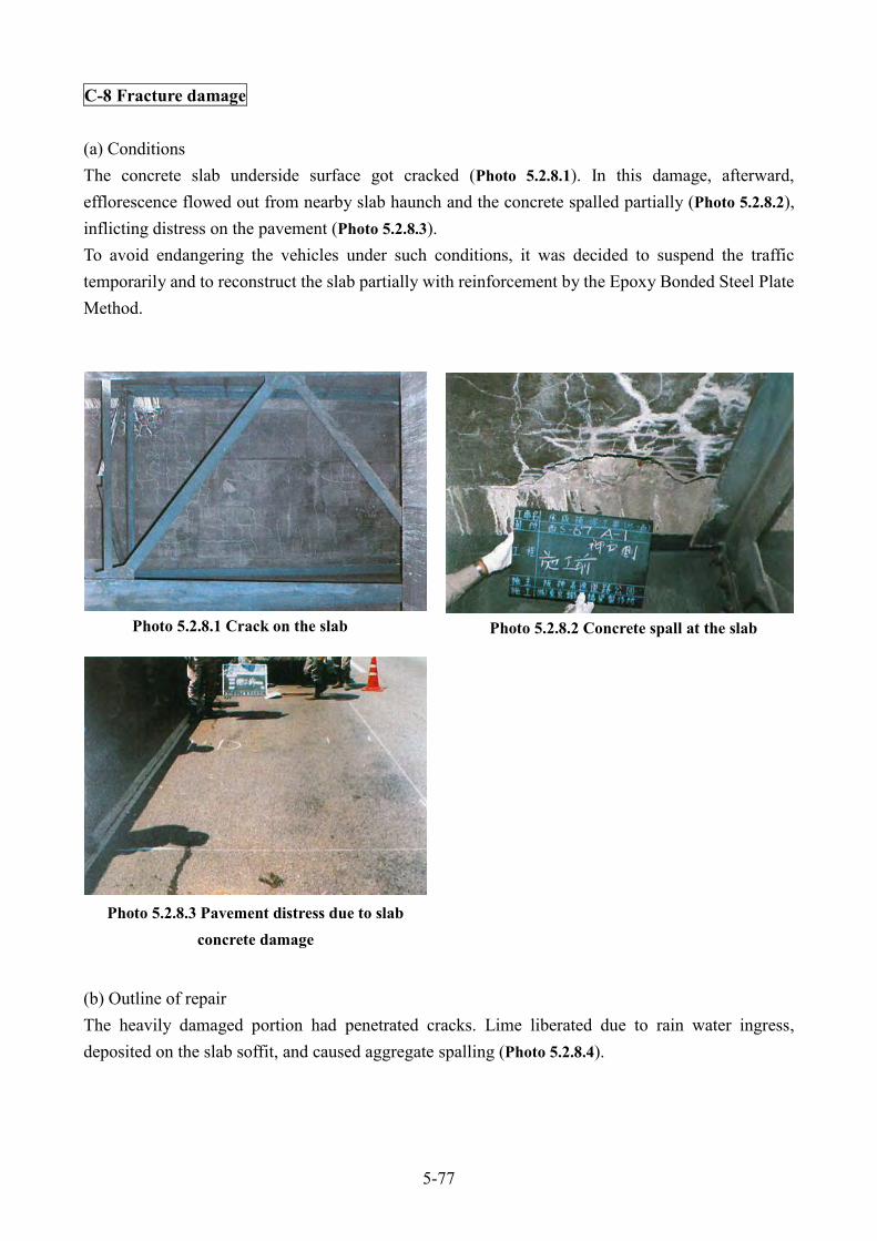
C-8 Fracture damage
(a) Conditions The concrete slab underside surface got cracked (Photo 5.2.8.1). In this damage, afterward, efflorescence flowed out from nearby slab haunch and the concrete spalled partially (Photo 5.2.8.2), inflicting distress on the pavement (Photo 5.2.8.3). To avoid endangering the vehicles under such conditions, it was decided to suspend the traffic temporarily and to reconstruct the slab partially with reinforcement by the Epoxy Bonded Steel Plate Method.
(b) Outline of repair The heavily damaged portion had penetrated cracks. Lime liberated due to rain water ingress, deposited on the slab soffit, and caused aggregate spalling (Photo 5.2.8.4).
Photo 5.2.8.1 Crack on the slab Photo 5.2.8.2 Concrete spall at the slab
Photo 5.2.8.3 Pavement distress due to slab concrete damage
5-78
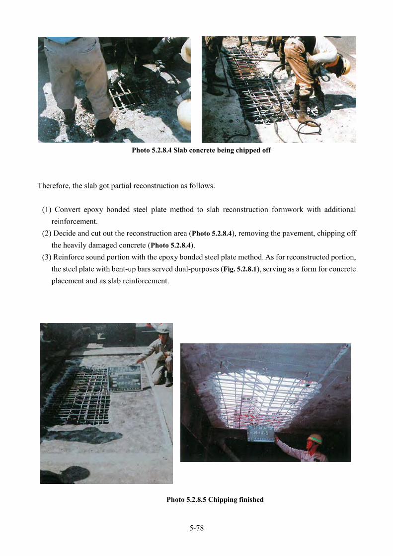
Therefore, the slab got partial reconstruction as follows.
(1) Convert epoxy bonded steel plate method to slab reconstruction formwork with additional reinforcement.
(2) Decide and cut out the reconstruction area (Photo 5.2.8.4), removing the pavement, chipping off the heavily damaged concrete (Photo 5.2.8.4).
(3) Reinforce sound portion with the epoxy bonded steel plate method. As for reconstructed portion, the steel plate with bent-up bars served dual-purposes (Fig. 5.2.8.1), serving as a form for concrete placement and as slab reinforcement.
Photo 5.2.8.4 Slab concrete being chipped off
Photo 5.2.8.5 Chipping finished

5-79
Fig. 5.2.8.1 Re-concreting of slab
Photo 5.2.8.6 Driving of hole in anchor Photo 5.2.8.7 Drilling finished
Photo 5.2.8.8 Steel plate attached Photo 5.2.8.9 Injection pipes and sealing are installed

5-80
(4) Concrete with ultra-high-strength cement, using field mixing to place concrete (Photo 5.2.8.11).
(5) To cure the placed concrete for about 4 hours, checking with the completed dimension (Photo 5.2.8.12).
Photo 5.2.8.10 Resin injection
Photo 5.2.8.11 Placing concrete
Photo 5.2.8.12 Checking re-concrete work
Photo 5.2.8.13 Pavement being placed and compacted

5-81
(c) Remarks The regular periodical inspection in November 1980 revealed this damage, ranked as level A in damage degree (Photo 5.2.8.1). This damage, thereafter, developed to level AA by 31 August 1981 (Photo 5.2.8.2). Like this case, the crack-penetrated slab degraded at an unexpected speed. Inspection with appropriate “prediction” is important. Two methods are available for the adhering steel plate to slab underside surface with epoxy resin. One is to give resin spread on the steel plate’s adhesion surface, to press the plate against the slab until resin cures (hardens), and to maintain for certain time the plate pressed against the slab, the pressure adhesion method (Fig. 5.2.8.2).
Another is to hold the steel plate with chinks between the slab, to give resin sealing along the steel plate’s edge all round, to inject an epoxy-based adhering agent in-between (Fig. 5.2.8.3). The injection pipe is usually installed at the lowest position. Epoxy is injected till the space is filled. The current repair works include the resin injection method, expecting resin pressure to fill the slab crack.
Fig. 5.2.8.2 Example of steel plate adhesion by pressure
Fig. 5.2.8.3 Example of the epoxy bonded steel plate method
5-82
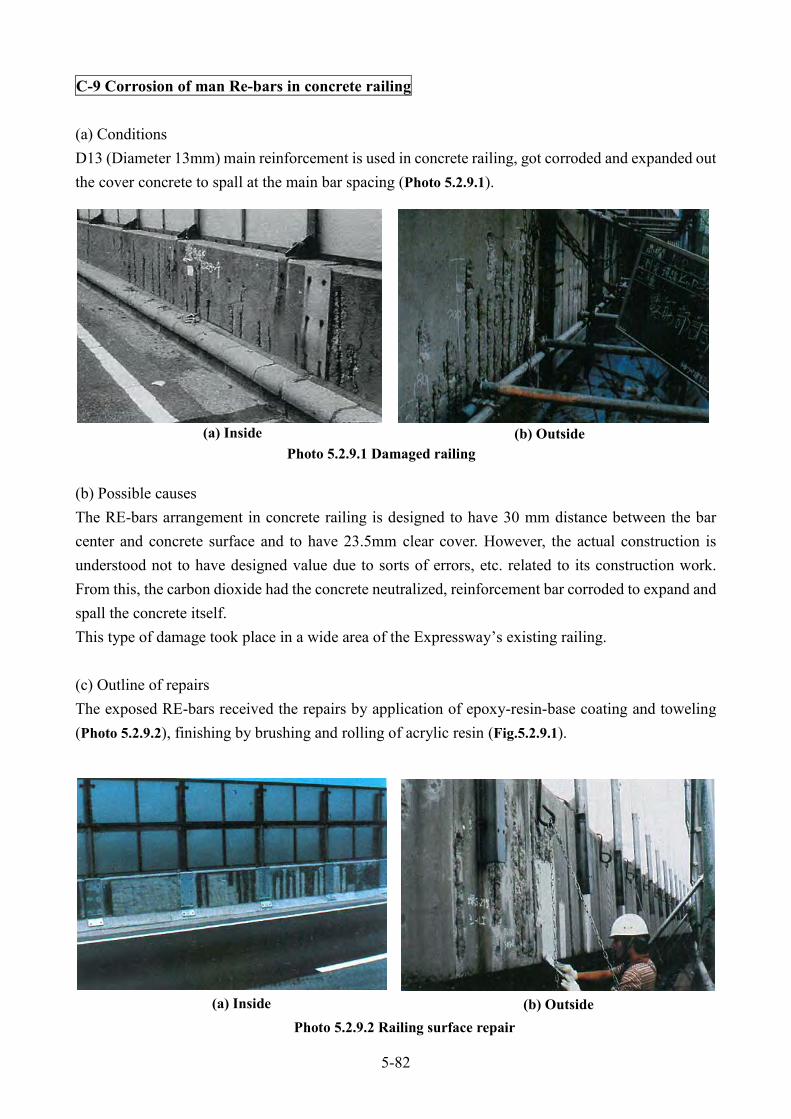
C-9 Corrosion of man Re-bars in concrete railing
(a) Conditions D13 (Diameter 13mm) main reinforcement is used in concrete railing, got corroded and expanded out the cover concrete to spall at the main bar spacing (Photo 5.2.9.1).
(b) Possible causes The RE-bars arrangement in concrete railing is designed to have 30 mm distance between the bar center and concrete surface and to have 23.5mm clear cover. However, the actual construction is understood not to have designed value due to sorts of errors, etc. related to its construction work. From this, the carbon dioxide had the concrete neutralized, reinforcement bar corroded to expand and spall the concrete itself. This type of damage took place in a wide area of the Expressway’s existing railing.
(c) Outline of repairs The exposed RE-bars received the repairs by application of epoxy-resin-base coating and toweling (Photo 5.2.9.2), finishing by brushing and rolling of acrylic resin (Fig.5.2.9.1).
Photo 5.2.9.1 Damaged railing (a) Inside (b) Outside
Photo 5.2.9.2 Railing surface repair (a) Inside (b) Outside

5-83
The procedure goes as shown in Fig. 5.2.9.2 and Photo 5.2.9.3 to Photo 5.2.9.8.
Fig. 5.2.9.1 Standard for repair work of exposed bars in railing
Fig. 5.2.9.2 Flow chart of repair work for concrete railing

5-84
(d) Remarks In new design type, the concrete cover is 45.5mm to expel this type of damage (Fig. 5.2.9.3). Furthermore, the concrete railing got embedding of welded steel netting (6.2mm×50mm×50mm mesh galvanized welding), inside by 1cm from concrete surface, to prevent flying of concrete pieces crashed asunder by vehicle collision.
Photo 5.2.9.3 Surface cleaning
Photo 5.2.9.4 Primary coat painting Photo 5.2.9.5 Tack-coating for second coat
Photo 5.2.9.6 Tack-coating for intermediate coating Photo 5.2.9.7 Intermediate coating of resin mortar

5-85
This type of damage with concrete spalling inflicts injury to drivers and pedestrians going by under the Expressway. Especially outside of the concrete railing, it is imperatively necessary to devise a drastically improved method for prevention of concrete spalling.
The lightweight concrete railing also experiences this type of damage, even with trend of larger concrete spalling than other types of concrete.
Photo 5.2.9.8 Top coating
Fig. 5.2.9.3 Bar arrangement in concrete railing
(a) Old design (b) New design

5-86
C-10 Vehicle Collision Damage on Concrete Railing
(1) Case 1 (a) Conditions Four vehicles running on the overtaking lane hit on one after another. The tail-end cargo vehicle steered to the left and collided with the concrete railing at an acute angle. The collision damaged the railing and its concrete fell (Photo 5.2.10.1). The damage, broke through RC railing wall, caused falling of 1.7m concrete lump downward from the Expressway. Although crack in the concrete railing spread over 4.45m in length, the concrete slabs underside surface was intact. (b) Outline of Repair Repair generally takes the following procedure in these types of concrete railing damaged.
1) Chipping concrete of the damaged portion. 2) Repairing and assembly of reinforcement. 3) Placing of super quick strength concrete. 4) Installing of blocks. 5) Finishing of repair.
Photo 5.2.10.1 Damage condition (Case 1)
Photo 5.2.10.2 Repair method (Case 1)
5-87
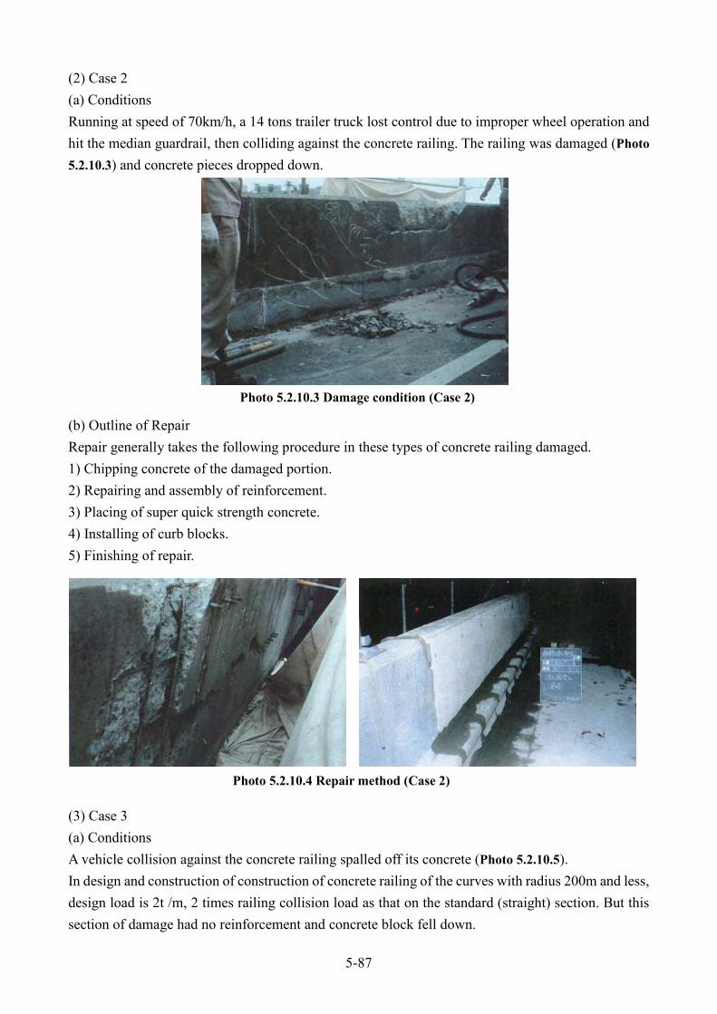
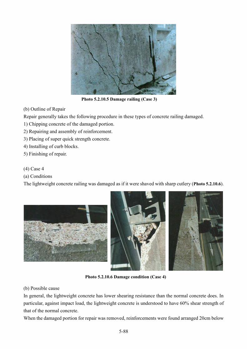
(2) Case 2 (a) Conditions Running at speed of 70km/h, a 14 tons trailer truck lost control due to improper wheel operation and hit the median guardrail, then colliding against the concrete railing. The railing was damaged (Photo 5.2.10.3) and concrete pieces dropped down. (b) Outline of Repair Repair generally takes the following procedure in these types of concrete railing damaged. 1) Chipping concrete of the damaged portion. 2) Repairing and assembly of reinforcement. 3) Placing of super quick strength concrete. 4) Installing of curb blocks. 5) Finishing of repair. (3) Case 3 (a) Conditions A vehicle collision against the concrete railing spalled off its concrete (Photo 5.2.10.5). In design and construction of construction of concrete railing of the curves with radius 200m and less, design load is 2t /m, 2 times railing collision load as that on the standard (straight) section. But this section of damage had no reinforcement and concrete block fell down.
Photo 5.2.10.3 Damage condition (Case 2)
Photo 5.2.10.4 Repair method (Case 2)
5-88
(b) Outline of Repair Repair generally takes the following procedure in these types of concrete railing damaged. 1) Chipping concrete of the damaged portion. 2) Repairing and assembly of reinforcement. 3) Placing of super quick strength concrete. 4) Installing of curb blocks. 5) Finishing of repair. (4) Case 4 (a) Conditions The lightweight concrete railing was damaged as if it were shaved with sharp cutlery (Photo 5.2.10.6). (b) Possible cause In general, the lightweight concrete has lower shearing resistance than the normal concrete does. In particular, against impact load, the lightweight concrete is understood to have 60% shear strength of that of the normal concrete. When the damaged portion for repair was removed, reinforcements were found arranged 20cm below
Photo 5.2.10.5 Damage railing (Case 3)
Photo 5.2.10.6 Damage condition (Case 4)

5-89
the concrete railing top. It proved the collided portion had no reinforcement, giving a “shaving off” of its concrete. (b) Outline of Repair Repair generally takes the following procedure in these types of concrete railing damaged. 1) Chipping concrete of the damaged portion. 2) Repairing and assembly of reinforcement. 3) Placing of super quick strength concrete. 4) Installing of curb blocks. 5) Finishing of repair. (5) Case 5 (a) Conditions Due to vehicle collision, the curved concrete railing was damaged for about 5m long (Photo 5.2.10.8).
Photo 5.2.10.7 Repair method (Case 4)
Photo 5.2.10.8 Damage condition (Case 5)

5-90
(b) Possible cause The cause for such a large scale damaged was excessive loading caused by vehicle collision. (c) Outline of Repair Repair generally takes the following procedure in these types of concrete railing damaged. 1) Chipping concrete of the damaged portion. 2) Repairing and assembly of reinforcement. 3) Placing of super quick strength concrete. 4) Installing of curb blocks. 5) Finishing of repair. (6) Remarks While the direct causes for the damages were excessive loading from vehicle collision, some of damages were due to improper reinforcement arrangement in its concrete. It, therefore, requires careful management in construction not to cause such incident.

5-91
C-11 Longitudinal Crack in the Lower Flange of PC Girder
(a) Condition A longitudinal crack was found along the sheaths on the lower flange of PC girder (Photo 5.2.11.1).
G4, the central girder, had crack of 0.5mm-1.0mm wide and approximately 18m long in its mid-span lower flange (Fig. 5.2.11.1). Two cracks spread in the longitudinal direction, dividing 60cm-wide lower flange into trisections and trace of efflorescence at places. The ultrasonic detector measured the estimated crack depth as 6cm to 10cm.
Photo 5.2.11.1 Crack on low flange

5-92
(b)Possible Causes Possible other causes are: (1) Growth of lateral tension strain equivalent to Poison’s ratio by pre-stressing. (2) Excessive pressure by the grout injection (3) Expansion pressure effect of grouting material due to expansion admixture. (4) Internal pressure effect generated from the difference of thermal expansion coefficient and
drying shrinkage between grout and concrete. (5) Secondary lateral strain generated by PC cable tension. (6) Lateral strain triggered by bucking of reinforcement bar.
A combination of some of these causes is understood responsible for this type of damage, as well as other factors such as construction workmanship (compaction, curing time length before formwork removal), etc. Eventually, it is a matter of great importance to design about the eligible arrangement of reinforcement (stirrups, etc.), so that a sufficient cover thickness provides rational compaction and curing.
Fig. 5.2.11.1 Cracked position

5-93
(c)Outline of Repairs The investigation confirmed the sheath completely filled with grout. To prevent corrosion from starting on reinforcement and PC cables, sealing to the cracks of 0.2mm and larger width was implemented through injection pipes positioned at 20cm interval along the cracking line. The repair was completed with the injection of epoxy resin grouts with pressure of about 0.2kg/m2 and with the surface finishing.
Fig. 5.2.11.2 Detail crack on low flange

5-94
C-12 Concrete Pier Damaged by Alkali-Aggregate Reaction
(a) Condition Fig.5.2.12.1 shows typical crack pattern in the column head caused by Alkali-Aggregate Reaction, illustrating wide cracks extending in horizontal direction.
The widest crack (Photo 5.2.12.1) was 4 to 5 mm in width, located in the position where the column reinforcement terminates at the beam center.
Fig. 5.2.12.1 Crack on the concrete pier beam
Photo 5.2.12.1 Crack caused by alkali-aggregate reaction (b)Abutment (b)Pier beam

5-95
As Fig. 5.2.12.2 shows, each side of cracks of the beam surface had about 4mm dislocation. Except for this cracks, other cracks were not deep and stayed within the cover concrete according to the random core sampling. This type of cracking was found out also in the abutment and its core samples are shown in Photo 5.2.12.1.
(b) Possible Cause This type of cracking, dislocation in the concrete surface, was caused by concrete expansion. The surface of cores sampled from the beam was carefully observed (Photo 5.2.12.2) in pursuit of the cause of the concrete expansion. The investigation confirmed aggregate reaction rings (Photo 5.2.12.3), and also revealed exudation of gel around each ring (Photo 5.2.12.4).
Fig. 5.2.12.2 Detail Crack on the concrete pier beam Photo 5.2.12.2 Surface observation by core sample
Photo 5.2.12.3 Reaction ring and crack inside of aggregate

5-96
A considerable elongation (expansion) was recorded through the measuring of variation of perimeter after core boring (Photo 5.2.12.5).
Powdered x-ray analyzing and deflective microscopic observation of mineral composition in the aggregate of sampled core revealed the presence of reactive minerals. From such outcome of observation, it was concluded that the damage was caused by alkali-aggregate reaction.
The alkali-aggregate reaction in this case, more precisely, is defined as the alkali-silica reaction. And such alkali-silica reaction takes place when the three factors, reactive silica (SiO2) in the aggregate, alkali metal (Na or K), and moisture-satisfy a certain condition, produce an alkali silica gel as follows,
SiO2+2NaOH+8H2O = Na2H2SiO4・8H2O
This gel is highly hygroscopic and expands by absorbing more moisture. The expansion in the surroundings of aggregate invites the expansion of concrete structure. The concrete structure gets cracked in its surface when it can no longer sustain such internal expansion.
(a) Gel exudation from aggregate (b) Exuded gel observes with Scanning Electron Microscope
(c) X-ray intensity spectrum by elements exuded gel
Photo 5.2.12.4 Exudation of gel around each ring
Photo 5.2.12.5 Sampled cores banded for change of perimeter measurement

5-97
(c) Outline of Repairs No research or studies of alkali-aggregate has ever presented any perfect method for repair. Presently, single conceivable repair method is the waterproof of existing concrete structure to eliminate one of the aforementioned three factors. Available single method is surface coating after injection of flexible epoxy resins of high elongation type into cracks to shut out the moisture ingress. Table-5.2.12.1 shows the coating specifications coded by ‘Hanshin express company limited (In Osaka, Japan)’ actually used in the repairing of existing structures. In general, if the base concrete can be completely cut off from the water, waterproof type is used. Otherwise, repellent water type is used.
Table-5.2.12.1 Concrete surface coating system (a) Repellent water type
Process Material
Coating conditions
Target film
Thickness(m
Standard
usage(kg/m2) Method
Pre-treatment Disc sander or Wire brushing
First coating Reactive silane impregnated material - 0.20 – 0.24 Brush or roller
Second coat Flexible polymer cement mortar 1050 - 1200 2.10 – 2.30 Brush or roller
Top coat Acrylic emulsion paint 60 – 80 0.20 Brush or roller
(b) Waterproof type
Process Material
Coating conditions
Target film
Thickness(m
Standard
usage(kg/m2) Method
Pre
-
treatment
Primer Epoxy or polyurethane primer - 0.1 Brush or roller
Putty Epoxy resin putty - 0.5 Spatula or trowel
Second coat 1 Flexible epoxy resin (Thick-film) 160 0.35 Roller
Second coat 2 Flexible epoxy resin (Thick-film) 160 0.35 Roller
Second coat 3 Flexible epoxy resin (Thick-film) 160 0.35 Roller
Top coat Flexible epoxy resin 30 0.12 Brush or roller
One of recommendable way is that resin-injection by reasonable pressure into these kinds of cracks. (Reference: 5.2 Case of Concrete structure repair C-1 Concrete crack)
In surface coating, brushing, roller, or spraying is generally applied. It is essentially important for the suppressing of alkali aggregating reaction to keep moisture content as low as possible. For the purpose, the concrete surface must be checked for its fair dryness before

5-98
the application of surface coating. However, this method is suitable for repair of structures damaged by cracks but not deficient structurally deficient. In the structural proof-stress, it should specifically be repaired by steel plate bonding, carbon fiber sheet bonding, pre-stress introduction, structural member increment, or re-concreting, etc. (d) Remarks Various types of examination, field investigation through repairs, have been conducted on the cracks caused by alkali-aggregate reaction. The followings are summary of discussion.
(1) Field investigation and examination of causes Table-5.2.12.2 shows the items of the field investigation carried out after finding cracks and of the core sampling examination to identify the causes of the defect.
Table-5.2.12.2 Investigation items on alkali-aggregate reaction
Method Item
Fiel
d in
vest
igat
ion Visual inspection on surface Crack width, depth, length, distribution
Hammering Cavity, Loosening
Schmidt rebound hammer test Compressive strength
Ultrasonic wave propagation velocity Crack depth, strength
Cor
e sa
mpl
ing
Visual inspection Sol, gel, reaction ring
Expansion measurement Open expansion, residual expansion
Aggregate analysis Grain distribution by rock types, polarizing photomicrograph,
Power X-ray diffraction
Cement analysis Mix proportions, cement used, amounts of alkalis and chlorine.
Strength test Compressive strength, elastic modulus, Poisson ratio,
neutralization depth
ASTM test (reproducibility) Chemical method, Mortal bar method
Gel analysis Alkali silica gel
(2) Proof test 1) Loading tests on model beams
Bending load tests were conducted on two model beams with the same reinforcement ratio as designed in the existing column. One model: a built beam with alkali-aggregate and wish typical cracks developed, and another: a beam with ordinary aggregate. The tests revealed the compressive strength of standard concreted test specimen decreased by 40% with reactive aggregate than with ordinary aggregate, however the both models gave no substantial

5-99
difference in structural behavior. This, in the model with reactive aggregate, can be well understood that chemical pre-stress is generated in the concrete sections because of reinforcement restraints against concrete expansion. In addition to this static bending test on RC-beam, dynamic bending test, shearing test, and RE-bar adhesion test were carried out on the RC-beam. Static and dynamic bending tests were also carried out on pre-stressed concrete beam.
2) Load tests on actual (existing) bridge Sound pier and damaged pier with alkali-aggregate reaction had little difference in their structural response under the live load condition.

6-1
CHAPTER 6 REPAIR OF STEEL STRUCTURE 6.1 Planning of Steel structure repair Before repair work, brief concrete bridge repair plan and cost estimation shall be prepared. In this manual, it is recommended that the planning and cost estimate should be done, and due consideration is revealed in the manual. The repair plan shall include;
- Province (DPWT) that manages the target bridge - Location - Priority - Repair method - Reference No. of unit costs for cost estimate (refer to “Appendix”), and - Repair cost
Approximate repair bridge cost can be obtained by summing each cost estimate. The typical repair code is shown in Table6.1.1. All repair code is described in ‘Appendix’
No. Code Repair Work Unit
1 2001 Steel Corrosion Repair m2
2 2002 Reinforcement by Steel Plate m2
In the repair execution plan, work priority order has to be determined with comprehensive considerations of time schedule, location, current severity of damages, route importance, and preference. Since the bridge maintenance technology is constantly evolving, road administrator must keep obtaining new knowledge by dense communication and information exchange with relevant organizations.
Table 6.1.1Typical bridge repair code (Steel)

6-2
6.2 Case of Steel structure repair This section is to introduce repair case studies of steel structures.
S-1 Corrosion on steel girder due to water leakage
(a) Conditions Corrosion was found at web, lower edge of the vertical stiffener and lower flange of the steel girder as shown in Photo 6.2.1.1.
The corrosion grew at the outer girder of 4 main girders at the center of the 2 span continuous non-composite I-girder bridge. Based on a thickness measurement by ultrasonic tester, the corrosion was judged as serious and it was confirmed that decrease of the thickness is by 5.2mm for the lower flange compared to the original design (Web: 9mm, lower flange: 16mm to 19mm). Also, a large amount of water leakage was found at the floor slab over the corroded area and a large amount of efflorescence had been deposited on the lower flange (Fig.6.2.1.1).
(b) Possible Causes It is assumed that deterioration was caused by the water leakage from the construction joint of slab concrete which was insufficiently treated, and that rainwater has gradually leaked to the lower flange for a long period of time as shown in Photo 6.2.1.2. Also, some of the wooden form which had accidentally came into the wrong position was left in the slab concrete during the construction (Fig. 6.2.1.1 and Photo 6.2.1.3). It is assumed that the deterioration had developed as follows.
Photo 6.2.1.1 Steel girder corrosion condition
Corrosion
Low Flange Girder web
Fig. 6.2.1.1 Condition for corrosion

6-3
Rainwater with efflorescence coming though the slab concrete was stored around the wooden form and immersed out whenever traffic passed through. This efflorescence accumulated on the lower flange, and kept the area wet all the time. Therefore, deterioration had developed.
(c) Repair outline Repainting is the normal repair method for this kind of deterioration. If the corrosion is very serious, placing of steel reinforcement with additional members after polishing the deteriorated area is usually used. Because of its extremely serious loss of thickness for the designed section, repainting was not sufficient for this damage. Also, the repair method could not be applied in this case because the repair should be done without any supports from the ground at the site. In addition, the traffic could not be suspended during this repair. Because of these, if the method would be applied, it would be very difficult to secure a stress transmission to the reinforcing members to observe whether the repair was effective or not. The alternative repair was carried out as follows (Fig. 6.2.1.2):
(1) Install temporary members at both ends of the corroded member to divert stress to attached member.
(2) Remove the corroded area from the original structural member.
(3) Install reinforcing member consisting of a prefabricated I-shaped girder with high-strength bolts for the web and by welding the lower flange to the main girder.
Photo 6.2.1.2 Water leakage from the construction joint of slab concrete
Photo 6.2.1.3 Wooden form which was left in the slab concrete
Wooden form

6-4
Prior to the repair work, the static test was carried out to confirm the effectiveness of the repair method and the dynamic test was done to investigate the most effective construction method at the site under traffic by utilizing a model girder. As the result of the static load test, it was clarified that temporary members (by-pass material) functioned well as a structural member to bear real stress when the original section was removed. The repair work could be completed under a stress-free condition.
Also, the following countermeasures were taken to keep a good condition for the work by taking into account of the test result.
Fig. 6.2.1.2 Procedure for the repair

6-5
(1) The groove (V-shape, back chipping) of the model girder produced a crack at the initial layer. Because of this, the groove shape was changed to an X-shape and the defective layer was removed by gouging.
(2) After placing a scallop on the web where welding lines cross, a overlapping weld system was performed.
(3) A vibration on the mother material was restrained as little as possible and the root gap was controlled as less than 1mm during the work at site.
After installing the new members, a water proof layer was placed on the slab to prevent water from leaking not to cause corrosion on the surface of the steel girder. Because the measurement showed that all internal stress was transferred onto the by-pass member when the deteriorated area was removed and there was no excessive stress around the area when the work was complete.
(d) Remarks Careful attention for preventing rainwater leakage from road surface shall be given to construction joints of the slab concrete and expansion joint because rainwater leakage develops serious corrosion on the steel girder. If the areas become rusty, action to stop the water leakage shall be immediately taken. Also, at the same time, partial re-painting shall be performed, if necessary. The method used for the work can also be applied to other type of girders. This method has a useful advantage because it can be completed in a short period without a temporary support from the ground under traffic load.

6-6
S-2 Cracks the jammed part connecting cross beam and vertical stiffener of I-girder (a) Conditions A crack was found at jammed part where so many members, such as cross beam sway bracing and main girder on the nearby upper flange and web, are connected by welding to the simple composite steel I-girder, as shown in Photos 6.2.2.1 and Fig.6.2.2.1.
Type 1 2 3 4
Cross
beam
Sway
bracing
These cracks have been observed on almost all kinds of similar structures. The cracks were classified as follows: (1) Many cracks were found at the simple composite I-girder bridge or H-girder Bridge. (2) Many cracks were found for bridges where the slab span is more than 3.5 meters and that the slab
thickness of 17 to 22 centimeters is thin compared with the conventional slab span (main girder spacing).
(b) Possible causes
Photo 6.2.2.1 Cracks the jammed part connection cross beam and vertical stiffener of I- girder
Fig. 6.2.2.1 Cracks pattern of simple composite I-girder

6-7
In order to investigate the cause, an elastic analysis was performed by using Finite Element Method with a solid model to review the stress condition in the damaged area. The result was outlined as follows: (1) Large bending moment three times bigger than the allowable stress was observed at the rib plate
and top of the vertical stiffener. Also, composite force of bending and shearing was observed at the jammed part welded with the rib plate and upper flange of the vertical stiffener (Fig. 6.2.2.2, Fig. 6.2.2.3).
Fig. 6.2.2.2 Structural members
Fig. 6.2.2.3 Stress diagram on the web

6-8
(2) The stress on the web of main girder is disturbed at the scallop and has a great influence on flow of stress.
(3) The weld part exhibits bending. It is caused by structural members, such as upper flange, web of the main girder, rib plate and vertical stiffener.
In order to confirm the reliability of the analysis results, a load test was performed under the same conditions as those for the analysis. The result shows that an excessive stress, exceeding the allowable stress which is not as large as that found in the analysis, exists at the welded part. The major causes according to the investigation are as follows: (1) An excessive secondary stress and its repetition caused by an oscillation phenomenon of slab due
to live load. (2) Concentrated stress due to existence of scallop. (3) Insufficient welding caused by a gap between rib plate or vertical stiffener and the flange due to
unskillful fabrication or assembly. This crack seems to be not so serious for soundness of the girder itself when it stays only on the rib plate or on the vertical stiffener. However, when it develops into the web of the main girder, an urgent repair and reinforcement work is required. (c) Repair Outline (1) Preliminary study of repair work The repair method shown in Fig. 6.2.2.4 was studied according to the results of the stress analysis.
Fig. 6.2.2.4 Stress diagram on the web

6-9
The proposed method for the repair has advantages as follows: 1) Shearing deformation generated on the rib plate of the present model was minimized. Also, local
bending deformation on the web of the main girder near the rib plate was eliminated. 2) Either main stress or equivalent stress was reduced to about 1/3 of that of the previous one. Also,
stress disturbance nearby the scallop was reduced. (2) Repair Method A new design for the welded part based on the result of stress analysis was made and a preliminary repair was applied on the damaged part. As a result, the stress generated round the welded part was considerably reduced and the expected purpose was attained. However, local deformation was formed on the upper flange of the girder due to welding heat. Therefore, an improved repair method was designed as follows:
1) After removing the damaged parts of the welded area, apply a sufficient welding on the necessary part.
2) Replace the present rib plate by a new thicker plate to distribute forces on cross beams. 3) Install a 12mm thick plate by welding around the upper rib of the vertical stiffener against the
sway bracing. 4) Scallop is not allowed on the plate mentioned in 2), 3) above. 5) The welding for the new plates to be connected with main girder, cross beam and sway bracing
must be strong enough for the stress obtained by an analytical design or test. (d) Remarks In this kind of repair works, trial work in advance must be considered to find problems and appropriate repair methods.

6-10
S-3 M-Cracks on connected part of gusset or lateral bracing around support of steel I-girder (a) Conditions The cracks shown in Fig.6.2.3.1 and Photo 6.2.3.1 were found on both welded parts of the main girder web and vertical stiffener connected with gusset for a lateral bracing at the end of the main girder, around the support, in the simple steel girder bridge. The characteristics of the cracks are as follows:
1) The simple steel composite I-girder has more cracks than the others. 2) Cracks have been found at the second panel of the main girder next to the outermost girder. 3) More cracks are observed at the superstructure support by a single T-type pier and on the slender
superstructure supported by a steel pier. This was found through survey of relation between types of cracks in substructure.
(b) Possible causes The causes can be summarized as follows on the characteristics of cracks and the results of elastic analysis by means of Finite Element Method by utilizing a complete solid model and a partial solid model.
1) A large axial force was found at the lateral bracing not only due to horizontal force caused by such as winds and earthquakes, that are normally considered in ordinary design, but also due to the vertical displacement difference between the main girders caused by dead loads, live loads and differential settlement of the support.
Fig. 6.2.3.1 Location of crack Photo 6.2.3.1 Condition of crack

6-11
2) A large axial force is introduced on the web of the inner main girder from both sides of the lateral bracing by a live load.
3) Stress generated by the axial force is in disorder at the position of the scallop on the gusset plate and makes a local deformation on the web of the main girder (Fig.6.2.3.2).
4) Repetition of the deformation develops cracks at the toe of welding near the scallop of the gusset. 5) As the deformation becomes larger, the cracks grow on the welded part of the vertical stiffener
on the support, too. (c) Repair Outline A repair method was examined by the internal committee. The proposed repair method and the results of analysis were shown below. Two repair methods were proposed as follows:
1) In order to eliminate the stress disturbance around the scallop of the gusset, the scallop must be buried by installing reinforcing plates as shown in Fig.6.2.3.3 (a).
2) Unless the plate is effective for improving the stress flow, additional reinforcing members with the plate must be added to support an imbalanced axial force transmitted from both sides of the lateral bracing as shown in Fig.6.2.3.3 (b).
According to Finite Element Method, the stress flow at the jointed part of the gusset can be sufficiently improved by eliminating the scallop. Effectiveness with additional members is almost the same as that with only reinforcing plates.
Fig. 6.2.3.2 Stress nearly gusset

6-12
(d) Remarks In the design for the secondary members, more careful attention is needed for the secondary stress and structure details that accompany deformation of the main girder.
Fig. 6.2.3.3 Example of repair method

6-13
S-4 Crack at haunch girder
(a) Conditions
A crack was found on the steel web and on the fillet welding area of lower flange at the hunched main girder as shown in Photos 6.2.4.1. Magnetic particle test revealed the crack dimension is in full size as shown in Fig. 6.2.4.1.
This bridge, simple composite girder bridge which consists of 6 main I-girders, has been operating for 13 years. In survey of the other I-girders on the same bridge, cracks were found at four places of filet welding area on the middle girders. Also, similar kinds of cracks were found on the same type of three other bridges, including two cracks which expanded from the welded area to the web.
This bridge had been repainted a year before the cracks were found. According to the results of
Fig. 6.2.4.1 Crack dimension in full scale drawing
Photo 6.2.4.1 Crack on steel girder
Stop hole

6-14
investigation, paint penetrated into the crack at the flange fillet welding, but it did not on the crack at web. It is assumed that the crack at the web developed about 60cm during the first year after repainting. Investigation by magnetic particle test showed obviously both a root failure of the weld bead and a toe failure of the mother material existed alternatively.
(b) Possible Causes The causes of damage clarified up to the present time were as follows:
(1) It was determined from the fracture surface observation that the crack was caused by fatigue.
(2) The root gap for fabrication of notched part is 2.1 mm maximum. This dimension is bigger than that of normal standard, but it is not the main factor according to research data in the past. However, a larger root gap will become one of factors for slag inclusion. Also, a larger root gap increases such possibilities as an occurrence of a small pit to introduce stress concentration at bottom of the weld bead due to increasing a residual stress or extending a root crack.
(3) Results according to Finite Element Method (FEM) show that a normal stress at the R-Shape notched section (One of local stress existing between a lower flange plate and a web) exceeds the ultimate strength of the welding material during loading of the design load. This will be one of causes to encourage development of fatigue crack.
(4) As long as a crack exists only in the welded zone of the flange plate, the overall stress is almost
the same as that of the sound structures. However, when the crack develops into the web the strength charged by the flange plate will be decreased and the stress acted on the web will be exceeded.
Therefore, while the crack stays in the R-shape notched section, it is not so serious from viewpoint on the strength of the structure. However, if the crack expands onto the web, it will introduce serious damage of the structure. Because of this, repair is necessary as soon as possible during the crack stays in the weld bead. (c) Repair Outline Repairing work for the crack reaching the web was carried out as follows:
(1) Confirming the location of the crack end on the web by means of SUMP photo, put a stop-hole with a diameter as big as the web thickness, at the point of the crack end.
(2) Reinforcing the I-girder with temporary support at 1/8 span of the girder, jack it up to remove the
dead load. (3) Keeping the notched part to be in the stress-free condition as much as possible, conduct the
welding with an x-shape groove at site after bead gouging.

6-15
(4) Placing splice plates with reinforced flanges at the both sides of the web, by high-strength bolts shown in Fig. 6.2.3.2 and Photo 6.2.3.2.
Fig. 6.2.4.2 Detail design of repair work

6-16
(5) In order to decrease a shear stress level, extend both ends of reinforced flanges vertically and horizontally at the corner according to a new design standard.
(6) Due to installation of new flanges the stress acted on the flange at the corner will be minimized
and the stress by the curved flange will be distributed to the splice plate. (7) With repainting the necessary parts complete the repair work.
(d) Remarks The major advantages to make a notched part on the main girder are as follows in case of hanging girders which has a different height because of a different length of the span.
1) To keep enough clearance underneath a girder. 2) To avoid constructing a step beam, 3) To adjust the horizontal level of bearings.
To relieve concentrated stress appeared at the haunch girder, a careful investigation for various kinds of the shape as shown in Fig. 6.2.4.3 was carried out. After the investigation with a load test, the new type of notches with reinforcing flanges was recommended in the present design standard.
Photo 6.2.4.2 Plates with reinforced flanges (a)Marking in full section web (b)Bolted condition
Fig. 6.2.4.3 Haunch girder

6-17
S-5 Steel pier corrosion
(a) Conditions
A serious corrosion due to an intensive dew condensation occurred in a steel pier as shown in Photo 6.2.5.1. In a steel pier, sometimes paint-missing fault (usually 2-layer coat with tar epoxy must be applied) occurred because of tight condition. Rust due to dew condensation inside of the pier as shown in Photo 6.2.5.1(b).
(b) Possible cause This kind of examples can be found out more often in structures with complicated shapes as shown in Fig. 6.2.5.1. The primary factors are assumed that the air circulation in the sealed area is not smooth because of its complicated shape, so dew condensation is introduced on the steel surface due to the temperature difference between inside and outside of structures.
(a)Remarkable dew condensation (b)Corrosion status (No painting)
Photo 6.2.5.1 Steel pier corrosion
Fig. 6.2.5.1 Steel pier sectional diagrams

6-18
More careful supervision at site must be taken to protect the paint-missing for coating in accordance with the standards at the joint area. (c) Remarks The best preventive way of this damage is to provide smooth ventilation. No perfect painting material is now available for repairing of such a closed area, then the repair work is rather difficult now. The following measures shall be taken in consideration.
(1) Painting of non-solvent paint Perfect ventilation in the use of tar epoxy resin paint for the jointed area can be applied on the fabrication of steel structures in a workshop. Especially for a safe of field working, however, it is difficult to provide perfectly controlled ventilation for repainting. In this context, non-solvent tar epoxy resin paint must be considered effective in such works. Characteristics of the non-solvent tar epoxy resin paint can be compared with that of solvent tar epoxy resin paint as shown in Table 6.2.5.1. A serious risk for using non-solvent paint is that it is greatly influenced by the temperature and that a setting time is very short. A low temperature is suitable for controlling a setting time, while a high temperature is useful for a promotion of a dry strength.
Solvent tar epoxy Non-solvent tar epoxy
Ventilation bad good
Dryness good bad
Rust proofing (for a bad surface) bad bad
Water proofing good good
Brush painting property good bad
Work safety bad good
Pot life n.a. bad
Economic view point good bad
(2) Spraying of urethane foam Corrosion on the steel material is mainly caused by oxygen and water. In order to isolate these items, solid urethane foam resin with an excellent thermal insulation effect was tentatively applied on the structures as shown in Photo 6.2.5.2.
Table 6.2.5.1 Comparison of utilization properties for solvent and non-solvent tar epoxy resin paint

6-19
The procedure is as follow: 1) Draining the steel pier. 2) Ventilation 3) Rust removal 4) Cleaning (wiping with a rag) 5) Primer coating 6) Urethane foam spraying.
For using solid urethane foam resins, it is necessary to confirm properties such as: 1) Applicability of a combustible material like petroleum, class IV. 2) Cost 3) Adhesive effect 4) Viability and durability to follow the deflection of steel structures
(a) Inspection (b) Ventilation
(c) Rigid urethane spraying
(d) Rigid urethane spraying Photo 6.2.5.2 Solid urethane foam resin

6-20
(3) Providing a ventilation system with no temperature difference. The condensation easily starts in high humidity. Also, when the humidity is low, a high temperature difference between the inside and outside is quite sensitive to initiate condensation. Therefore, it is useful to provide manholes covered by a wire net (to protect entering of birds) to keep a smooth ventilation.

7-1
CHAPTER 7 REPAIRE OF FOUNDATION OR OTHER STRUCTURE 7.1 Case of other bridge structure repair This section is to introduce repair cases of other bridge structures.
J-1 Damage on Expansion joint (a) Conditions For any bridges, expansion joints are essential components in order to adjust its displacement caused by such factors as temperature variation, concrete creep and shrinkage. However expansion joints are the weakest point among bridge structure components and their failure may cause unevenness on road surface and hinder smooth movement of vehicles. Rubber joint and steel finger types are mostly used for the purpose of keeping road continuous and adjusted due to temperature change or live load. It is, however, rather difficult to provide a high quality joint to satisfy the requirements sufficiently. There are several patterns of damages on expansion joints which are discussed below. (b) Possible causes Main causes of the damage to expansion joints are as follows:
1) As traffic volume and vehicle load increase, expansion joints of bridges suffer from abrasion and fatigue failures
2) Inadequate choice of expansion joints for a long-span bridge, skewed bridge or curved bridge causes malfunction, or they are not anchored properly to the main girders.
3) When a level difference exists between the expansion joint and the concrete deck of abutment parapet due to faulty construction, impact of vehicle’s weight becomes greater and inflicts damage to expansion joints on bridge decks.
It is difficult to identify the cause of expansion joint damage, as the damages appear in a combination of several adverse conditions. Major causes mentioned above can be classified into several factors shown as follows:
1) Design factors * Insufficient rigidity of the slab ends,
* Insufficient rigidity of expansion joint body, * Insufficient strength of expansion joint anchor members, * Mistakes in the selection of mounting materials, * Miscalculation of maximum expansion due to temperature change and creep, * Misallocation of drain facilities and drain water inlet.
2) Construction Factors * Construction error in slab spacing, * Insufficient construction control for mounting materials.
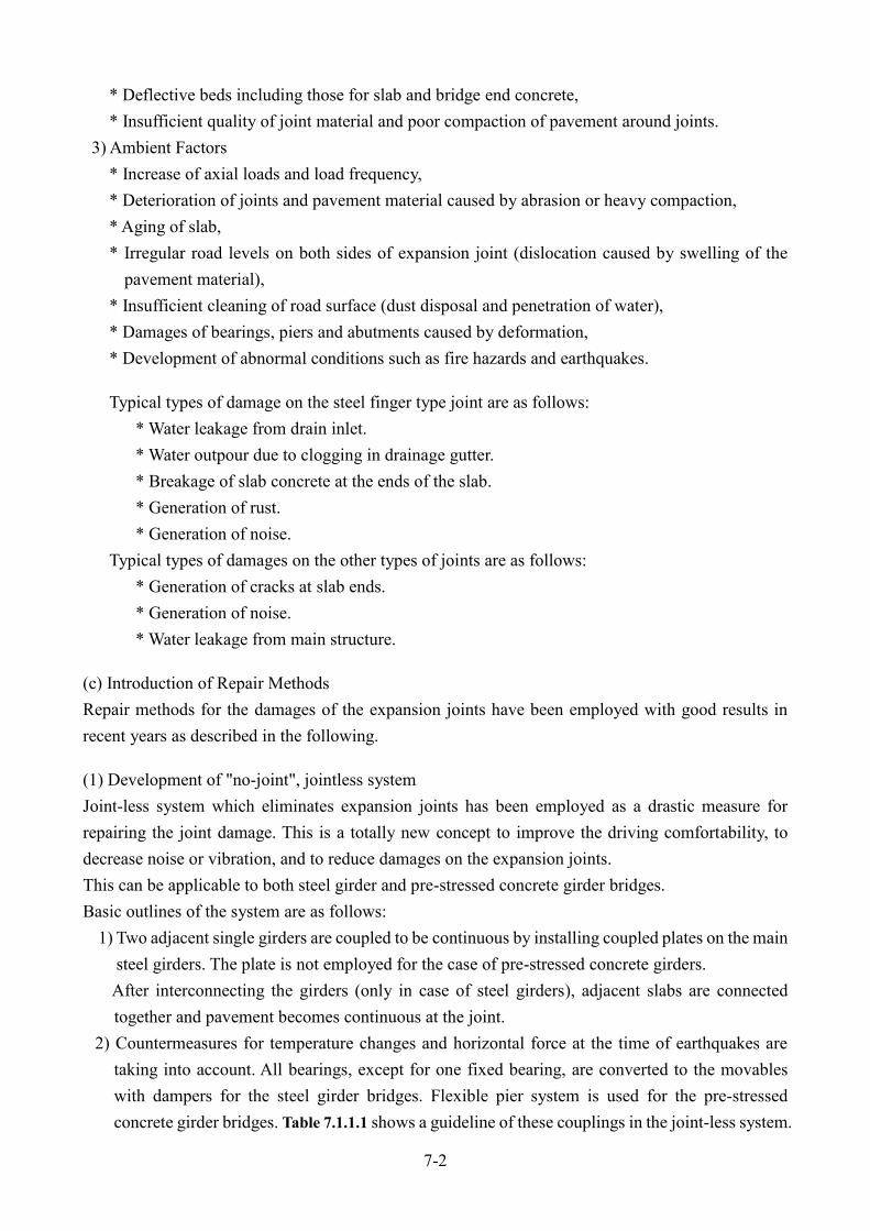
7-2
* Deflective beds including those for slab and bridge end concrete, * Insufficient quality of joint material and poor compaction of pavement around joints.
3) Ambient Factors * Increase of axial loads and load frequency, * Deterioration of joints and pavement material caused by abrasion or heavy compaction, * Aging of slab, * Irregular road levels on both sides of expansion joint (dislocation caused by swelling of the
pavement material), * Insufficient cleaning of road surface (dust disposal and penetration of water), * Damages of bearings, piers and abutments caused by deformation, * Development of abnormal conditions such as fire hazards and earthquakes.
Typical types of damage on the steel finger type joint are as follows: * Water leakage from drain inlet. * Water outpour due to clogging in drainage gutter. * Breakage of slab concrete at the ends of the slab. * Generation of rust. * Generation of noise.
Typical types of damages on the other types of joints are as follows: * Generation of cracks at slab ends. * Generation of noise. * Water leakage from main structure.
(c) Introduction of Repair Methods Repair methods for the damages of the expansion joints have been employed with good results in recent years as described in the following.
(1) Development of "no-joint", jointless system Joint-less system which eliminates expansion joints has been employed as a drastic measure for repairing the joint damage. This is a totally new concept to improve the driving comfortability, to decrease noise or vibration, and to reduce damages on the expansion joints. This can be applicable to both steel girder and pre-stressed concrete girder bridges. Basic outlines of the system are as follows:
1) Two adjacent single girders are coupled to be continuous by installing coupled plates on the main steel girders. The plate is not employed for the case of pre-stressed concrete girders. After interconnecting the girders (only in case of steel girders), adjacent slabs are connected together and pavement becomes continuous at the joint.
2) Countermeasures for temperature changes and horizontal force at the time of earthquakes are taking into account. All bearings, except for one fixed bearing, are converted to the movables with dampers for the steel girder bridges. Flexible pier system is used for the pre-stressed concrete girder bridges. Table 7.1.1.1 shows a guideline of these couplings in the joint-less system.

7-3
Steel girder PC girder
Cou
plin
g sy
stem
Con
ditio
n an
d re
actio
n
forc
e sp
read
ing
syst
em Change from fixed bearings to movable bearing.
Stress spreading is done by means of viscous fracture
model damper
The current bridge bearing conditions are maintained.
Reaction force spreading is done by means of “ flexible
pier” system
Out
line
of p
roce
dure
1) By connecting the top flanges of main girders with a splice
plate, decrease the deformation of the connecting deck slab.
2) Continue deck slabs, and settle a buffer layer with a Styrofoam
plate between the slab and girders to absorb the deformation
due to rotation of girders.
3) Connect the top flanges of the end cross beams with a kin plate
(6 -8mm), which is also used as the foam concurrently.
4) For the crack in deck slab, execute an anti-corrosive treatment
to the reinforcing bars and perform a water proof coating on
the deck slab.
5) For the thermal expansion of girders and transmission of
horizontal seismic forces caused by continuing the top flanges
and deck slab, though it is desired to absorb these forces by the
deformation of the foundations and the piers, it will not be
enough. Exchange therefore every fixing bearing into movable
bearing except one and settle a damper system between girders
and piers instead.
1) Continue deck slabs of girder ends, and settle a buffer layer
made of a Styrofoam plate between the slab and the girder to
separate their behaviors.
2) Because deck slabs will not be supported at the girder ends
due to executing the term i), expand the haunch of the end
cross beams and support the slab.
3) For the crack in deck slab, execute an anti-corrosive
treatment to the reinforcing bars and perform a water proof
coating on the deck slab.
4) For the thermal expansion of girders and transmission of
horizontal seismic force caused by continuing the deck slabs,
absorb these forces by the deformation of the foundations and
the piers.
Table 7.1.1.1 Guideline of joint-less system

7-4
Detailed structural analysis is carried out for coupling parts as the key components of the system. Static and dynamic tests were executed by using a large scale model in a research laboratory. Later, on the occasions of a major repair work by closing road traffic, the system has been applied to several bridges as shown Photo 7.1.1.1 at several sections.
No abnormality has been appeared so far and, it is convinced that this application has been successful. Furthermore, a simplified joint-less system for the shorter span girders has been conducted tentatively.
This could be classified into the following two methods: 1) Method by hexagonal panel:
A light weight steel plate, hexagonally shaped porous panel is built in the asphalt pavement. Because of this arrangement, the rigidity and toughness of deformation of the pavement are improved. (Fig.7.1.1.1 (a), Photo 7.1.1.2).
Photo 7.1.1.1 Construction of joint-less system

7-5
(a) Method by hexagonal panel
(c) Idle space adjustment
(b) Method by expand metal
Fig. 7.1.1.1 Simplified joint-less system

7-6
2) Method by expand-metal:
The expand-metal is buried in the pavement, instead of the hexagonal-panel. This method aims to improve the rigidity and toughness against the pavement deformation. This also aims to get high ability for shear deformation of the water-proof layer installed on the surface of the slab. (Fig.7.1.1.1 (b)) As a result of these applications, cracks in the pavement surface were found for the hexagonal panel after about one year. The cracks were observed at locations where unevenness or bumping on the slab surface were conspicuous. This suggested that it was important to give smooth finish in construction when this method was applied.
(2) Watertight system on steel finger joints In the current design standard for new construction, this system with stainless steel gutter has been already introduced instead of the conventional drain type. However, concerns still remain to be unimproved with the rainwater leakage from the joint’s gutter. To eliminate the problem of water leakage, the watertight system on the steel finger joints is applied, as the design standard recommended, using elastic sealing materials. Brief construction procedure of the system is as follows:
1) Taking away old type water gutters 2) Placing water cut-off member (made of thermoplastic elastomer) underneath the face plate of
the finger joints. 3) Pouring the elastic sealing material (of poly-buthan-diethylene or like).
All works, except for around curb stones, must be done on the road surface. Fig. 7.1.1.2 and Fig. 7.1.1.3 show the procedure of the works by the foamed water cut-off member. (As for the elastic sealing material, refer to Fig. 7.1.1.4 and Photo 7.1.1.7, respectively)
Photo 7.1.1.2 Joint less method by hexagonal panel
Joint less line
Incomplete line

7-7
(a) Before the work (b) Withdrawal of water gutter, cleaning
(c) Welding of supporting plate (d) Insert the formed water cut-off member
(e) Installation of fixing band, painting
Fig. 7.1.1.2 Improvement of water gutter by formed water cut-off member

7-8
(a) Improved type (b) Conventional type
Fig. 7.1.1.3 Improvement of water gutter by formed water cut-off member (2 types)
Photo 7.1.1.3 Cleaning of the web surface
Photo 7.1.1.4 Setting of formed water cut-off material
Photo 7.1.1.5 Installation of supporting metal pieces

7-9
Fig. 7.1.1.4 Improvement of water gutter by elastic sealing material
(a) Adhesive coating and installation of back-up material
(b) Pouring of elastic water cut-off material
(c) Withdrawal of back-up material and painting
(a) Installation of back-up material (b) Pouring of elastic sealing
(c) Finished work Photo 7.1.1.6 Improvement of water gutter by elastic sealing material

7-10
(d) Remarks Damage of expansion joints not only causes traffic troubles but also causes discomfort and dangerous sensations to the drivers. Moreover, it has such serious effects as damaging slabs, causing rust generation and corrosion in the bearings and the bridge structures, especially on the steel bridge. At the same time, the noise and vibrations caused by passing vehicles inflict great discomfort to the inhabitants of the surrounding area. Being subjected to direct loads, expansion joints are susceptible to the damage. And once they are damaged, expansion joints are so difficult to be repaired that many problems arise in maintaining and managing them because of their locations. Because an expansion joint is directly subjected to the impact force of vehicles, it must be firmly attached to the main body of the bridge. Although it is also difficult to restore them perfectly to the original state, it is often necessary to replace the whole equipment or to change to another type of structure depending on the damage. In recent years in Japan, due to increase of traffic volume and heavy weight vehicles the conditions are aggravating. In consequence, even a slight defect in construction becomes the cause of a joint damage. Further, due to the restrictions imposed by the works conditions, sufficient repair measures cannot always be taken, so that it becomes necessary to perform repair now and then. Suggestions for the maintenance of expansion joints As even a slight defect in the expansion joint may develop into major damage, the best policy in management would be the early discovery of defects. However, when the damage reaches a advanced stage and restoration by routine management becomes no longer appropriate, it is essential that repair be performed before any serious consequences are generated. In the case of the expansion joint selection, it is necessary to give consideration to the following points.
a) Investigation of the cause of damage, b) Nature of the Expressway in terms of service, c) Bridge type……Construction of slab and bridge ends, d) Required expansion movement and joint spacing, e) Desired characteristics of expansion joint to be selected, such factors as:
- Durability, - Levelness, - Water tightness, - Maintainability - Economical advantages.
As it is difficult to judge such matters as the 1) thickness at the slab ends, 2) degree of damage and 3) abnormality in the joint gap from the road surface, it will be necessary to chip off a part of the slab concrete, or a part of the bridge end, or the whole slab and to perform repair depending on the type of the expansion joint. During chipping work, particular attention must be paid toward avoiding

7-11
damages to the RE-bars in the slab concrete. Particularly careful attention is required for pre-stressed concrete bridges as the anchoring of PC steel wires will be found concentrated in the bridge end sections.
Although in the constructions following factors are assumed; 1) the performance of each expansion joint and 2) the classification and type of the bridge in design and construction work. It is necessary to reexamine these factors before starting repair work. Generally, the optimum type of expansion joint must be selected as i) design expansion amount, ii) design minimum joint gap and design maximum joint gap, and iii) allowance. By taking these into account, the capability and features of the expansion joints will be decided. In setting up the repair work plan, restriction relating to traffic measures, construction method must be taken into account.

7-12
J-2 Bridge scour Spread footings on soil or erodible rock shall be located so that the top of footing is below the design flood against bridge scour and the bottom of footing is below scour depths determined by the check flood for scour. Spread footings on scour-resistant rock shall be designed and constructed to maintain the integrity of the supporting rock. Deep foundations with footings shall be designed to place the top of the footing below the estimated degradation plus contraction scour depth to minimize obstruction to flood flows and resulting local scour. Even lower elevations should be considered for pile-supported footings where the piles could be damaged by erosion and corrosion from exposure to stream currents. Where conditions dictate a need to construct the top of a footing to an elevation above the streambed, attention shall be given to the scour potential of the design.
Fig. 7.1.2.1 Ground line from the foundation
Fig. 7.1.2.2 Spread footings of the bridge

7-13
The stability of abutments in areas of turbulent flow shall be thoroughly investigated. Exposed embankment slopes should be protected with appropriate scour countermeasures. Abutment footings shall be designed so as to be stable for permanent loads and hydraulic forces assuming the loss of approach fill. Deep foundations may be necessary. (a) Conditions The most common cause of bridge failures is caused by floods scouring bed material from around bridge foundations. In 1985, 73 bridges were destroyed by floods in Pennsylvania, Virginia, and West Virginia in USA. The 383 bridge failures caused by catastrophic floods showed that 25 percent involved pier damage and 75 percent involved abutment damage in 1973, USA. (b) Possible causes Total scour at a highway crossing is comprised of three components. Aggradation and Degradation:
These are long-term streambed elevation changes due to natural or human-induced causes within the reach of the river.
Contraction Scour: This type of scour involves the removal of material from the bed and banks across all or most of the width of a channel. Most commonly, this scour is the result of a contraction of the flow (Fig. 7.1.2.3 and Photo 7.1.2.2).
Photo 7.1.2.1 Condition of Bridge Score
Fig. 7.1.2.3 Approach embankments

7-14
Local Scour:
This scour occurs around piers, abutments, spurs, and embankments and is caused by the acceleration of the flows and the development of vortex systems induced by these obstructions to the flow Fig. 7.1.2.4 and Photo 7.1.2.3).
Photo 7.1.2.2 Narrow river width by old bridge abutment
Fig. 7.1.2.4 Schematic representation of scour at a cylindrical pier
Photo 7.1.2.3 Schematic representation of scour at a cylindrical pier

7-15
(c) Outline of repair work The selection of a countermeasure depends on the type of scour involved. Different materials scour at different rates. Loose granular soils are rapidly eroded under water action while cohesive or cemented soils are more scour-resistant. However, ultimate scour in cohesive or cemented soils can be as deep as scour in sand-bed streams. Scour will reach its maximum depth by materials as follows;
In sand and gravel bed materials in hours; Cohesive bed materials in days; Glacial tills, poorly cemented sand stones and shales in months; Hard, dense and cemented sandstone or shales in years; And granites in centuries; a) Reduction of cause Before carrying out the repair work, it is necessary to remove the cause of scouring as possible. In the previous case of Photo 7.1.2.2, because the abutment of the old bridge wasn’t removed, the river flow increased in rainy season, and the scouring progressed at an early stage. In this bridge, the old abutment of unnecessary had to be removed not to interfere with the river flow. And as much trash is accumulated under the bridge shown Photo 7.1.2.4, it is needed to clear debris regularly because of the similar concern. b) Countermeasures for contraction scour Design alternatives to decrease contraction scour include longer bridges, superstructures at elevations above flood stages of extreme events, and a crest vertical profile on approach roadways to provide for overtopping. These design alternatives are integral features of the highway facility which reduce the contraction at bridges and, therefore, reduce the magnitude of contraction scour.
Photo 7.1.2.4 Trash under the bridge

7-16
In general, design alternatives against structural failure from local scour consist of measures which reduce scour depth, such as pier shape and orientation, and measures which retain their structural integrity after scour reaches its maximum depth, such as placing foundations in sound rock and using deep piling. The reinforcement of abutment and pier for scouring is shown in Fig.7.1.2.5-Fig.7.1.2.7.
The stone size may be decided by the following formula. V/(gy)1/2 ≦ 0.80 ( V2/gy ≦ 0.64)
Where: D50 ; Median stone diameter (m) V ; Characteristic average velocity in the contracted section (explained below) (m/s) Ss ; Specific gravity of rock riprap
g ; Gravitational acceleration (9.81 m/s2) y ; Depth of flow in the contracted bridge opening (m) K ; 0.89 for a spill-through abutment 1.02 for a vertical wall abutment
Fig. 7.1.2.5 Plan view of the extent of rock riprap apron

7-17
Countermeasures which can reduce the risk from local scour include placing armor (e.g., riprap) at the structure or installing monitoring devices.
Fig. 7.1.2.6 Typical of cross section for abutment riprap
Fig. 7.1.2.7 Riprap layout diagram for pier scour protection

Attachment

Ministry of Public Works Transport, Cambodia
BRIDGE REPAIR WORK JOB SHEET
Code : 1 - 00001 Item : Concrete Crack Repair
Standard * Concrete cracks are filled with epoxy resin injection
* This method for concrete crack repairing is relatively less expensive than other methodologies.
Work Method * This repair work is carried out by dividing three days
Material *Epoxy resin *Sealant (Sealing)
*Syringes set *Thinner
*Chalk *Clay
Tool (Main) *Platform scale *Trowel
*Wire brush *Air blower
*Stopwatch
*Plastic cup *Plastic plate
Safety Signs and Devices *Scaffolding
*Glove
*Site Cleaning tool
Expensed *Repair material (Epoxy resin, Sealant, Syringes set Thinner etc.)
*Labor cost *Site inspection cost *Transport worker and material cost
*Equipment hire *Safety cost
Remarks * This method for concrete crack repairing is relatively less expensive than other methodologies.
Reference: C-1 Concrete crack

Ministry of Public Works Transport, Cambodia
BRIDGE REPAIR WORK JOB SHEET
Code : 1 - 00002 Item : Concrete Defect repair
Standard * After the degradation part of the concrete is removed by chipping, new concrete part is restored.
Work Method *After the degradation part of the concrete is removed by
chipping, new concrete part is restored.
* In practice, it is carried out survey before the repair work because of check peeling and the floating of the concrete by hitting test or visual survey.
*Since the high durability of the repair material is required, the polymer cement mortar material is usually used.
Material *Polymer cement mortar
*Primer
Tool (Main) *Generator
*Disc sander
*Hydraulics breaker
*Mortar mixer
*Trowel
*Plastic plate
Safety Signs and Devices *Scaffolding
*Glove
*Site Cleaning tool
Expensed *Repair material (Polymer cement mortar, Primer etc.) *Rental Fee
*Labor cost *Site inspection cost *Transport worker and material cost
*Equipment hire
Remarks

Ministry of Public Works Transport, Cambodia
BRIDGE REPAIR WORK JOB SHEET
Code : 1 - 00003 Item : Carbon Fiber Cloth (CFC) Reinforcement method
Standard * This method is applied to the concrete structure of insufficient strength such as construction defect,
design defect, strength lack due to overloaded vehicles.
Work Method *Reinforced by carbon fiber cloth
*If concrete deficit is large, it is used in
conjunction with the ‘Concrete Defect
repair method’.
*The carbon fiber sheet adheres to the existing concrete member,
combines for reinforced between the fibers by synthetic resin
adhesive.
Material *Carbon fiber Cloth (CFC)
*Primer
*Smoothing agent
*Impregnating resin
Tool (Main) *Generator
*Disc sander
*Trowel
*Plastic plate
Safety Signs and Devices *Scaffolding
*Glove
*Site Cleaning tool
Expensed *Repair material (Carbon fiber cloth, Primer etc.) *Rental Fee
*Labor cost *Site inspection cost *Transport worker and material cost
*Equipment hire
Remarks * This method isn’t needed heavy equipment.
Reference : C-2 Carbon Fiber Cloth (CFC) Reinforcement Method

Ministry of Public Works Transport, Cambodia
BRIDGE REPAIR WORK JOB SHEET
Code : 1 - 00004 Item : Reinforcement by Steel Plate (Concrete structure)
Standard * This method is applied to concrete slab of insufficient strength such as construction defect, design defect,
strength lack due to overloaded vehicles.
Work Method *Reinforced by steel plate
*To be spliced steel plate, dead load of the slab is increased. If this method is applied, the bearing and the
pier must be confirmed whether the reinforcement is necessary. For this reason, it is necessary to prepare
the design document of the repair bridge.
Material *Steel Plate
*Anchor bolt
*Painting
*Grout (cement between tile squares)
*Epoxy resin
Tool (Main) *Generator
*Drilling machine
*Electric hoist
*Disc sander
Safety Signs and Devices *Scaffolding
*Glove
*Site Cleaning tool
Expensed *Repair material (Steel plate, Anchor bolt etc.) *Rental Fee
*Labor cost *Site inspection cost *Design coat
*Transport worker and material cost *Equipment hire *Safety cost
Remarks * This method must be confirmed whether the reinforcement of bearing or pier is necessary.
To confirm whether the
reinforcement is necessary

Ministry of Public Works Transport, Cambodia
BRIDGE REPAIR WORK JOB SHEET
Code : 2 - 00001 Item : Steel Corrosion Repair
Standard * Corroded parts are repainted.
Work Method *The corrosion part is re-painted after cleaning to
see surface of the iron by disc sander
* Re-paint in a 5 layer (include zinc rich coating)
Material * Paint (undercoating,
second coating, final coating)
* Thinner
Tool (Main) *Generator
*Disc sander
*Brush
*Roller
Safety Signs and Devices *Scaffolding
*Glove
*Site Cleaning tool
Expensed *Repair material (Paint, Thinner etc.) *Rental Fee
*Labor cost *Site inspection cost *Transport worker and material cost
*Equipment hire
Remarks

Ministry of Public Works Transport, Cambodia
BRIDGE REPAIR WORK JOB SHEET
Code : 2 - 00002 Item : Reinforcement by Steel Plate (Steel structure)
Standard * This method is applied to reinforce the loss part by corrosion.
* This method is applied to reinforce of insufficient structure such as design defect, strength lack due to
overloaded vehicles.
Work Method *The rust part is removed the by disc sander.
*The deficit part is reinforced by spliced plate. It is designed to
determine the size or spliced method of the spliced plate. For this
reason, it is necessary to prepare the design document of the repair
bridge.
* If the existing spliced plate need to be removed, it is necessary to
carefully consider the removal method.
Material *Steel Plate
*High strength bolt
*Painting
*Thinner
Tool (Main) *Generator
*Impact wrench
*Drilling machine
*Electric hoist *Disc sander
* Brush *Roller
Safety Signs and Devices *Scaffolding
*Glove
*Site Cleaning tool
Expensed *Repair material (Steel plate, High strength bolt etc.) *Rental Fee
*Labor cost *Site inspection cost *Design coat
*Transport worker and material cost *Equipment hire *Safety cost
Remarks *This method must be designed to determine the size or spliced method of the spliced plate.
* If the existing spliced plate need to be removed, it is necessary to carefully consider the removal method.


Name List of People Involved with
Guideline for Bridge Inspection and Repairing
Prepared by
1. Mr. Chhim Phalla Director, Road Infrastructure Department
2. Mr. You Dara Deputy Director, Road Infrastructure Department
3. Mr. Sitthy Panhavuth Deputy Chief Office, Road Infrastructure Department
4. Mr. Nin Menakak Deputy Chief Office, Road Infrastructure Department
5. Mr. Eam Sovisoth Deputy Chief Office, Road Infrastructure Department
6. Mr. Long Davuth Officer, Road Infrastructure Department
7. Mr. Chhouk Sochea Officer, Road Infrastructure Department
8. Mr. Nut Sovanneth Officer, Road Infrastructure Department
Technical Contribution from
1. Mr. Koichi OGAWA JICA Chief Advisor
2. Mr. Yuzo MIZOTA JICA Expert
3. Mr. Masatoshi WATANABE JICA Expert
4. Mr. Ken TOKUMASU JICA Expert
5. Mr. Shiegeaki TSUKAMOTO JICA Expert
Edit and Comments from Routine Maintenance Working Group
1. H.E Touch Chankosal Secretary of State, Ministry of Public Works and Transport
2. H.E Lim Sidenine Secretary of State, Ministry of Public Works and Transport
3. H.E Yit Bunna Under Secretary of State, Ministry of Public Works and Transport
4. H.E. Nou Vaddhanak General Directorate of Techniques
5. H.E. Heng Rathpiseth General Directorate of Public Works
6. Mr. Nay Chamnang Deputy General Directorate of Administration
7. Mr. Chhim Phalla Director, Road Infrastructure Department
8. Mr. Khuon Kompheak Chief Officer, Road Infrastructure Department
9. Mr. Sun Chan Chief Officer, Road Infrastructure Department
10. Mr. Kem Socheat Chief Officer, Road Infrastructure Department
11. Directors and Deputy Directors of 25 Provincial and Municipal Public Works and Transport