chapter 5: digital logic - jufiles.comjufiles.com/wp-content/uploads/2016/12/lecture-14.pdfwe have...
TRANSCRIPT
Digital Logic Lecture 14
Synchronous Counters
By
Ghada Al-Mashaqbeh
The Hashemite University
Computer Engineering Department

The Hashemite University 2
Outline
Introduction.
Synchronous counters.
Regular (binary) synchronous counters.
Irregular synchronous counters.
Frequency dividers.
Examples.

The Hashemite University 3
Counters I
Counter: A Sequential Circuit that counts clock pulses.
Also, Counters are registers that store numeric values along with circuits to increment/decrement the stored value.
Counters has a specified states. For example you have to construct a counter that counts as follows: 0, 1, 2, …, 7, 0, 1… So, it is very easy to construct the state diagram.

The Hashemite University 4
Counters II
Basically, counters have no external inputs neither external outputs. Only we are care about the present and next states of the flip flops. only we need an external input which is the
control line for the up-down counters design.
You can use any flip flop type to construct counters (D, T, and JK flip flops).
However, JK and T flip flops are preferred to construct counters than D flip flops since they need less gates due to the existence of the toggling state.
The Hashemite University 5
Counters II
Counters are also called mod-n or modulo-n counters. For example, mod-5 counter counts from 0 to 4 (with a step width of 1) and so on.
We will use the general design procedure that
we have learned in chapter 5 to design synchronous counters.
Also, counters are called frequency dividers since they divide the frequency of the original clock.
The Hashemite University 6
Types of Counters I
Counters types based on the counting sequence: up-counters.
E.g. counts 0, 1, 2, 3, 0, …
down-counters. E.g. counts 3, 2, 1, 0, 3, …
up-down counters. The same counter with a control line can be up and
down counter at the same time.
Random counters. E.g. counts 0, 3, 2, 5, 4, 0, …
generalized counters E.g. BCD counters (0 - 9), Gray-code counters, ...
The Hashemite University 7
Types of Counters II
Types of counters based on clocking: Synchronous (parallel) counters: all flip flops are
connected to the same clock. It has two types: Regular (binary counters). Irregular (counters with unused states and random counters).
Ripple (asynchronous) counters: flip flops are not connected to the same clock. It has two types: Regular (binary counters). Irregular (counters with unused states and random counters).
We will study Synchronous Counters only
in our course.

The Hashemite University 8
Regular (Binary) Counters I
Binary counters are three types: Up counters. Down counters. Up-down counters.
Up regular counters have the following characteristics: The initial state is 0. The final state is the maximum unsigned number
that can be stored in m-bits where m is the number of flip flops used in the counter.
The step width is 1. The next state is 1+present state.

The Hashemite University 9
Regular (Binary) Counters II
Down binary or regular counters have the following characteristics: The initial state is is the maximum unsigned number that
can be stored in m-bits where m is the number of flip flops used in the counter.
The final state is 0. The step width is 1. The next state is present state - 1.
Up-Down regular counters: The same circuit is used to count in both directions (i.e. up
and down). Only in this type of counters we have external inputs (at
least one input) which are used as control lines to determine whether the counter will be up or down.
The Hashemite University 10
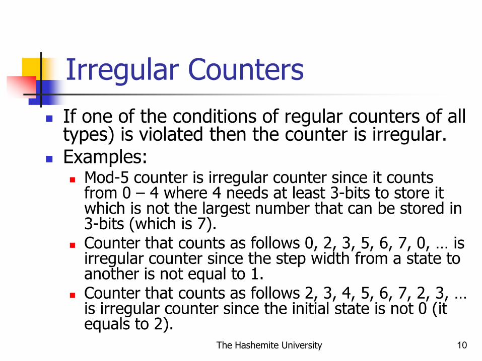
Irregular Counters
If one of the conditions of regular counters of all types) is violated then the counter is irregular.
Examples: Mod-5 counter is irregular counter since it counts
from 0 – 4 where 4 needs at least 3-bits to store it which is not the largest number that can be stored in 3-bits (which is 7).
Counter that counts as follows 0, 2, 3, 5, 6, 7, 0, … is irregular counter since the step width from a state to another is not equal to 1.
Counter that counts as follows 2, 3, 4, 5, 6, 7, 2, 3, … is irregular counter since the initial state is not 0 (it equals to 2).
The Hashemite University 11
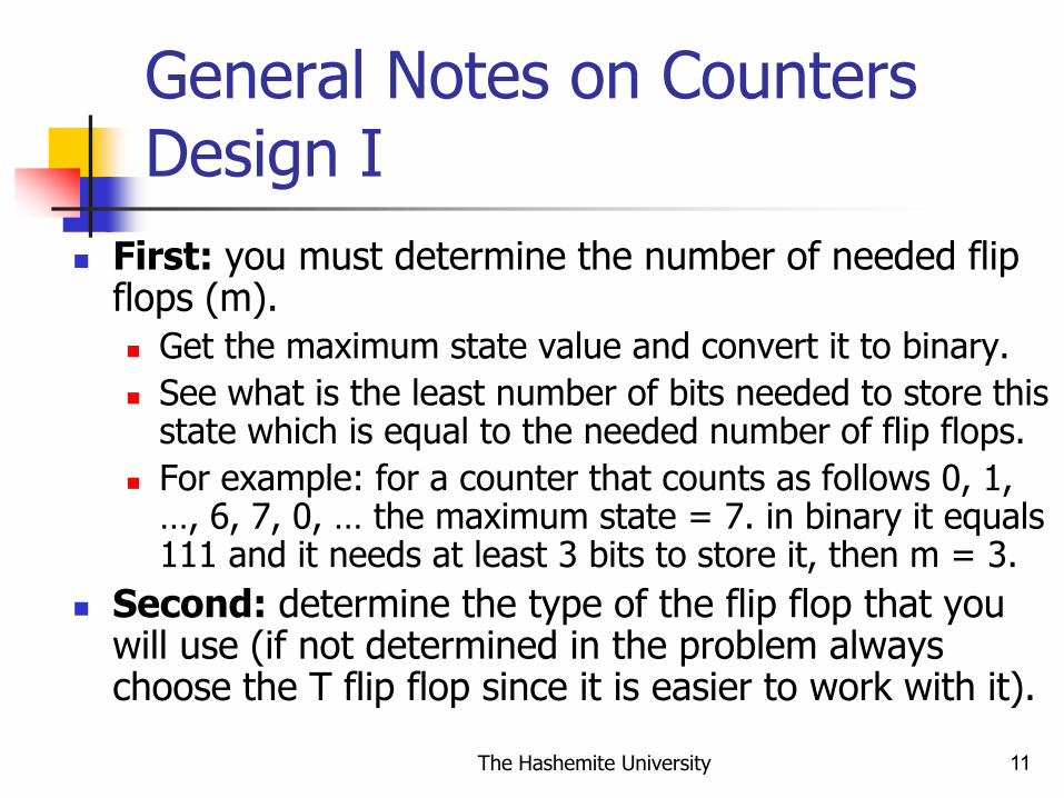
General Notes on Counters Design I
First: you must determine the number of needed flip flops (m).
Get the maximum state value and convert it to binary.
See what is the least number of bits needed to store this state which is equal to the needed number of flip flops.
For example: for a counter that counts as follows 0, 1, …, 6, 7, 0, … the maximum state = 7. in binary it equals 111 and it needs at least 3 bits to store it, then m = 3.
Second: determine the type of the flip flop that you will use (if not determined in the problem always choose the T flip flop since it is easier to work with it).

The Hashemite University 12
General Notes on Counters Design II
Third: determine whether these flip flops are +ve edge triggered or –ve edge triggered.
Fourth: determine what is the initial state of these flip flops which is the starting state of the counter. For the previous example the starting state of the counter is
0 so you assume that all flip flops are initially at 0 state (reset state).
Another example: lets have a counter counts as follows: 2, 3, 4, 5, 6, 7, 2, …. Here we need 3 flip flops Q2Q1Q0. The initial state is 2 so you will have initially Q2 = 0, Q1 = 1, Q0 = 0.
The Hashemite University 13
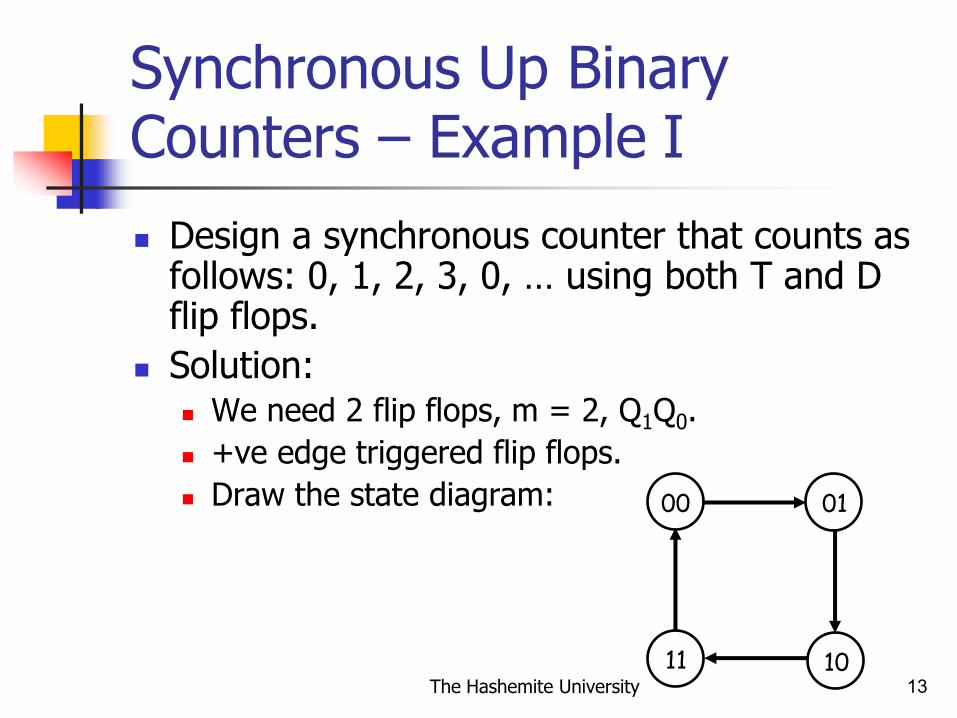
Synchronous Up Binary Counters – Example I
Design a synchronous counter that counts as follows: 0, 1, 2, 3, 0, … using both T and D flip flops.
Solution: We need 2 flip flops, m = 2, Q1Q0.
+ve edge triggered flip flops.
Draw the state diagram: 00 01
10 11

The Hashemite University 14
Synchronous Up Binary Counters – Example II
Next fill the state diagram which contains the present state, the next state, and the inputs of the flip flops (both T and D flip flops).
Fill the inputs of the flip flops based on the excitations tables.
Q1 Q0 Q1(t+1)
0
0
1
1
0
0
1
1
T1 T0 D1 D0
00
0
0
11
1
1
0
0
1
1
1
1
1
1
00
0
0
11
1
1
Q0(t+1)

The Hashemite University 15
Synchronous Up Binary Counters – Example III
Obtain the Boolean expressions of the flip flops inputs using K-maps.
Remember that we are working in parallel (design with both D and T flip flops).
For the T flip flop: T0 = Q0
T1 = 1
For the D flip flop: D0 = Q0’ D1 = Q0’Q1 + Q0Q1’ = Q0 XOR Q1

The Hashemite University 16
Synchronous Up Binary Counters – Example IV
Finally draw the circuits.
With T flip flops:
With D flip flops:
T0 Q0 T1 Q11
Clk
D0 Q0 D1 Q1
Clk
Q0' Q1'

The Hashemite University 17
Simplified Design Procedure for Synchronous Up-Binary Counters I
This method is applied for T and JK flip flops.
Every flip flops will toggle when all previous Q’s (lower order) must be 1 (connect them with AND gate).
The LSB flip flop Q0 is always toggling. So, its J = K = 1, or its T = 1.
The initial state is 0. so all flip flops must be at 0.

The Hashemite University 18
Simplified Design Procedure for Synchronous Up-Binary Counters II
Example: design a mod-8 synchronous counter using T flip flops. Mod-8: counts 0-7 and we need 3 flip flops.
It is regular counter. So, simply all previous Q’s must be 1 to toggle.
T0 Q0
Clk
T1 Q1 T2 Q21

The Hashemite University 19
Synchronous Down-Binary Counters – Home Exercise
Design a synchronous counter that counts as follows: 7, 6, …, 2, 1, 0, 7, … using JK flip flops.
Sol:
We need 3 flip flops, m = 3, Q2Q1Q0.
+ve edge triggered flip flops.
Draw the state diagram:
110
000 001 010
011
100101
111
The Hashemite University 20
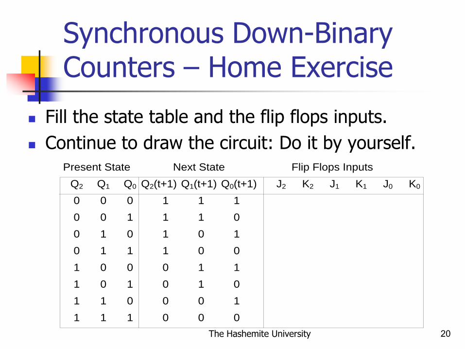
Synchronous Down-Binary Counters – Home Exercise
Fill the state table and the flip flops inputs.
Continue to draw the circuit: Do it by yourself.
Q1 Q0 Q1(t+1)
0
0
1
1
0
0
1
1
K2 J1
0
1
1
1
10
1
1
0 0
1 1
1
1
1
1 0
0 1
1
1
1 1
0
Q0(t+1)Q2 Q2(t+1)
0
0
0
0
0
0
Present State Next State Flip Flops Inputs
J2
0
010
00
10
1
0
K0J0K1

The Hashemite University 21
Simplified Design Procedure for Synchronous Down-Binary Counters I
This method is applied for T and JK flip flops. Every flip flops will toggle when all previous
Qs (lower order) must be 0: Connect Q’ to NAND to get 1 when this condition
is met.
The LSB flip flop Q0 is always toggling. So, its J = K = 1, or its T = 1.
The initial state is that all flip flops must be at 1.

The Hashemite University 22
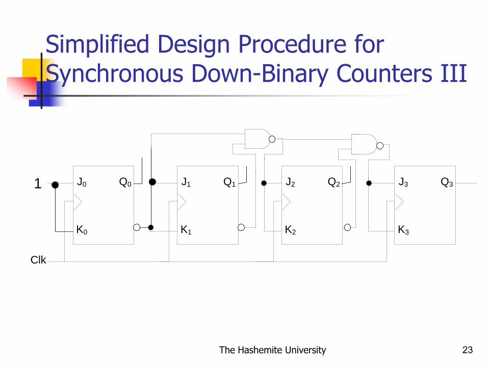
Simplified Design Procedure for Synchronous Down-Binary Counters II
Example: design a synchronous counter that counts as follows 15, 14, …, 1, 0, 15, …. Using JK flip flops. We need 4 flip flops.
The initial state of these flip flops is 1111 (state 15)
It is regular counter. So, simply all previous Q’s must be 0 to toggle.
So use NAND gate to connect Q’ of all previous FFs to get when all are 0s.
See the next slide.
The Hashemite University 23
Simplified Design Procedure for Synchronous Down-Binary Counters III
Q0
Clk
J0
K0
Q1 Q2J1
K1
J2
K2
Q3J3
K3
1

The Hashemite University 24
Synchronous Up-Down Binary Counter Design
The same counter with a control line can count up and down.
Must use the general design procedure to construct up-down regular counters (no simplified design procedures).

The Hashemite University 25
Synchronous Up-Down Binary Counter – Example I
Let’s try to design a slightly different two-bit counter:
Again, the counter outputs will be 00, 01, 10 and 11.
Now, there is a single input, X. When X=0, the counter value should increment on each clock cycle. But when X=1, the value should decrement on successive cycles.
We will use JK flip flops.

The Hashemite University 26
Synchronous Up-Down Binary Counter – Example II
Sol:
We need two flip flops, m = 0, Q1Q0.
Draw the state diagram:
00 01
10 11
0
0
0
1 0 1
1
1
The Hashemite University 27
Synchronous Up-Down Binary Counter – Example III
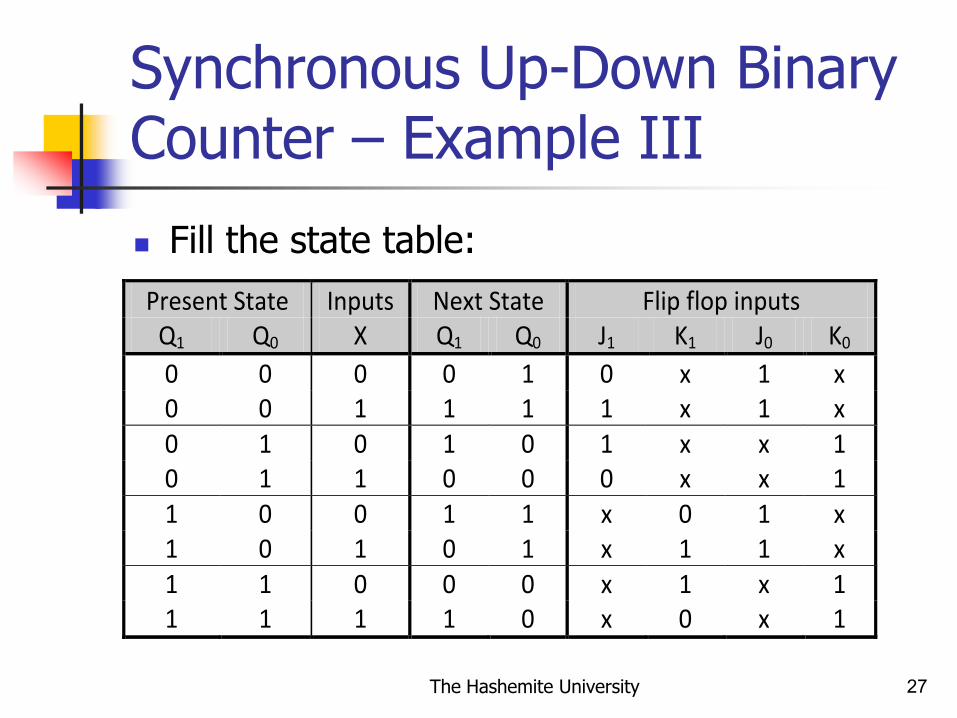
Fill the state table:
Present State Inputs Next State Flip flop inputs Q1 Q0 X Q1 Q0 J1 K1 J0 K0
0 0 0 0 1 0 x 1 x 0 0 1 1 1 1 x 1 x 0 1 0 1 0 1 x x 1 0 1 1 0 0 0 x x 1 1 0 0 1 1 x 0 1 x 1 0 1 0 1 x 1 1 x 1 1 0 0 0 x 1 x 1 1 1 1 1 0 x 0 x 1
The Hashemite University 28
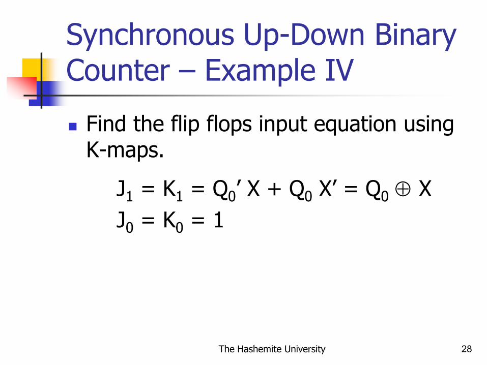
Synchronous Up-Down Binary Counter – Example IV
Find the flip flops input equation using K-maps.
J1 = K1 = Q0’ X + Q0 X’ = Q0 X
J0 = K0 = 1

The Hashemite University 29
Synchronous Up-Down Binary Counter – Example V
Draw the circuit:
J0 Q0 J1 Q1
Clk
Q0' Q1'K0 K1
X
1
The Hashemite University 30
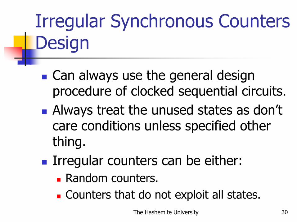
Irregular Synchronous Counters Design
Can always use the general design procedure of clocked sequential circuits.
Always treat the unused states as don’t care conditions unless specified other thing.
Irregular counters can be either:
Random counters.
Counters that do not exploit all states.

The Hashemite University 31
Example I
Design a synchronous mod-6 counter using T flip flops.
Sol:
Mod-6 counts 0-5, so we need 3 T flip flops.
Draw the state diagram:
000
101 100 011
010001

The Hashemite University 32
Example I .. Cont.
Fill the state table based on the state diagram and the excitation table of the T flip flop.
Note that there is unused states such as state 110 and 111 in the present state. We do not care about the next states for
these present states
and so we do not care about the flip flops inputs for these states.

The Hashemite University 33
Example I .. Cont.
Q1 Q0 Q1(t+1)
0
0
1
1
0
0
1
1
T1 T0
0
0
0
0
11
1
1
0 0
1 1
1
1
1
1 0
0 0
0
1
1 1
1
Q0(t+1)Q2 Q2(t+1)
0
0
0
0
0
0
Present State Next State Flip Flops Inputs
T2
X
000
XX
XX
1
X
X
XX
XX
X
1
1
1
0
1
0
0
0
0
0
1
1
1
1
0
1
01

The Hashemite University 34
Example I .. Cont.
Using K-maps obtain the Boolean expressions of the flip flops inputs:
T0 = 1
T1 = Q2’Q0
T2 = Q2Q0 + Q1Q0 = Q0 (Q2 + Q1)
The Hashemite University 35
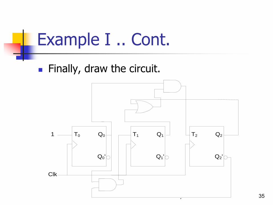
Example I .. Cont.
Finally, draw the circuit.
T0 Q0 T1 Q11
Clk
Q0' Q1'
T2 Q2
Q2'
The Hashemite University 36
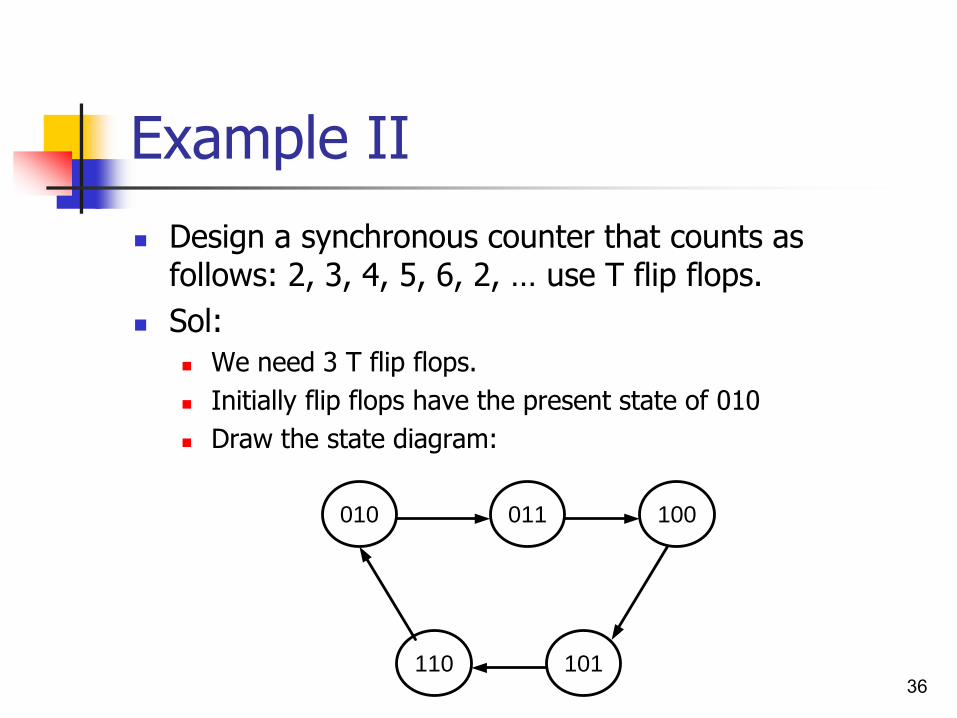
Example II
Design a synchronous counter that counts as follows: 2, 3, 4, 5, 6, 2, … use T flip flops.
Sol:
We need 3 T flip flops.
Initially flip flops have the present state of 010
Draw the state diagram:
010
110 101
100011

The Hashemite University 37
Example II … cont.
Fill the state table.
Q1 Q0 Q1(t+1)
0
0
1
1
0
0
1
1
T1 T0
X
0
X
X
11
X
X
0 0
1 1
1
1
1
1 0
0 0
X
1
1 1
1
Q0(t+1)Q2 Q2(t+1)
0
0
0
0
0
0
Present State Next State Flip Flops Inputs
T2
0
011
XX
01
1
X
1
XX
00
X
1
X
X
0
X
X
0
X
X
0
1
1
1
1
0
1
01

The Hashemite University 38
Example II … cont.
Complete the solution of the example by yourself.
What is remaining is obtaining the inputs equations of the flip flops using K-maps and sketch the circuit.

The Hashemite University 39
Example III
Design a synchronous counter that counts as follows: 2, 1, 4, 3, 7, 2, 1, … use T flip flops.
Sol:
We need 3 T flip flops.
Initially flip flops have the present state of 010
Draw the state diagram:
010
111 011
100001

The Hashemite University 40
Example III … cont.
Fill the state table.
Continue the solution.
Q1 Q0 Q1(t+1)
0
0
1
1
0
0
1
1
T1 T0
0
0
1
X
10
0
X
1 1
1 1
1
1
1
1 0
0 1
X
1
1 1
0
Q0(t+1)Q2 Q2(t+1)
0
0
0
0
0
0
Present State Next State Flip Flops Inputs
T2
X
XXX
10
XX
1
0

The Hashemite University 41
Simplified Design Procedure for Irregular Synchronous Mod-n Counters with Direct Inputs Flip Flops (Initial State is 0) I
If the flip flops that are used in the design are supported with a Reset or Clear input (when activated the flip flop is reset Q = 0) this can simplify the design of mod-n irregular synchronous counters.
For example: if you want to design a mod-5 counter (counts from 0 to 4) where you use T flip flops with active low reset input.
In this example the states greater than 4 are not allowed to appear.
Exactly after reaching state 4 (when state 5 appears) all flip flops must reset (return to their initial state 0).

The Hashemite University 42
Simplified Design Procedure for Irregular Synchronous Mod-n Counters with Direct Inputs Flip Flops (Initial State is 0) II
So, at that time simply activate the reset inputs of all flip flops to force them to return to state 0 (which is the initial state).
When you reach state 5 the present state is 101 which is (in minterms) Q2Q1’ Q0
Two cases exist:
Active low clear input.
Active high clear input.
The Hashemite University 43
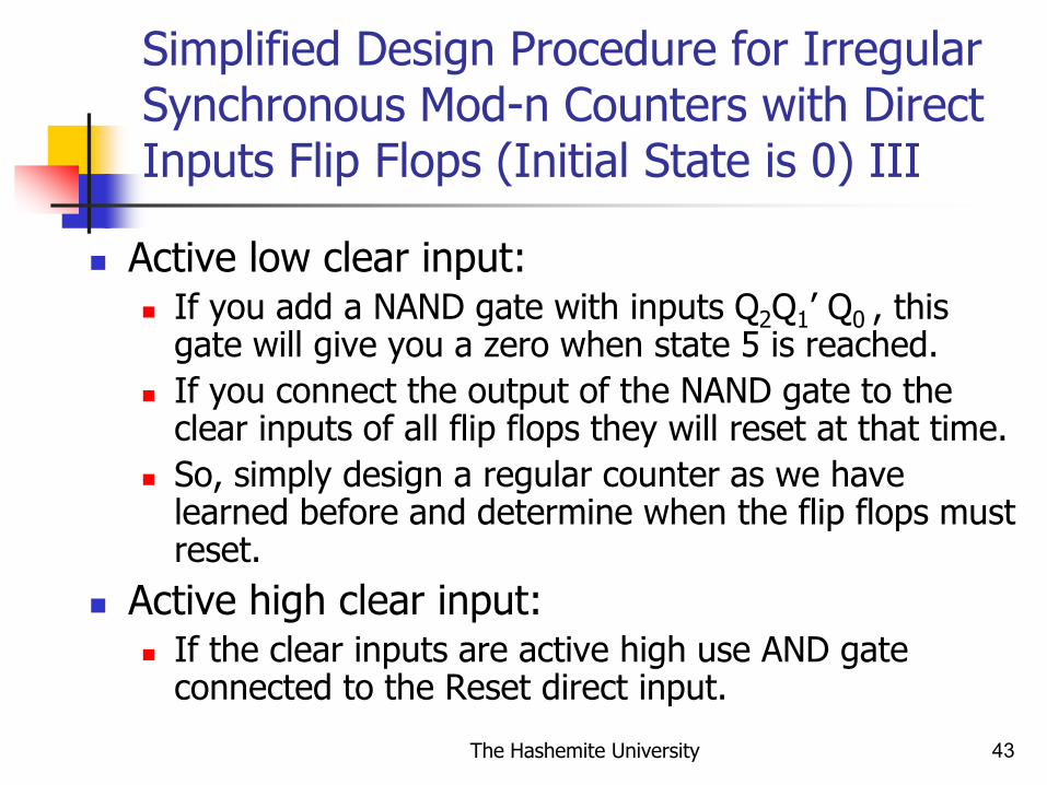
Simplified Design Procedure for Irregular Synchronous Mod-n Counters with Direct Inputs Flip Flops (Initial State is 0) III
Active low clear input: If you add a NAND gate with inputs Q2Q1’ Q0 , this
gate will give you a zero when state 5 is reached.
If you connect the output of the NAND gate to the clear inputs of all flip flops they will reset at that time.
So, simply design a regular counter as we have learned before and determine when the flip flops must reset.
Active high clear input: If the clear inputs are active high use AND gate
connected to the Reset direct input.

The Hashemite University 44
Example
Design a synchronous mod-5 counter. Use T flip flops with clear inputs.
T0 Q0
Clk
T1 Q1 T2 Q2
Clear ClearClear
Q0
Q1
Q2
1
The Hashemite University 45
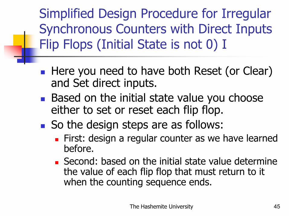
Simplified Design Procedure for Irregular Synchronous Counters with Direct Inputs Flip Flops (Initial State is not 0) I
Here you need to have both Reset (or Clear) and Set direct inputs.
Based on the initial state value you choose either to set or reset each flip flop.
So the design steps are as follows: First: design a regular counter as we have learned
before.
Second: based on the initial state value determine the value of each flip flop that must return to it when the counting sequence ends.

The Hashemite University 46
Simplified Design Procedure for Irregular Synchronous Counters with Direct Inputs Flip Flops (Initial State is not 0) II
For example if you want to design a counter that counts as follows: 2, 3, 4, 5, 2, … The initial state is 2.
After we reach the state 5 we must return to 2.
So, exactly when state 6 appears (which is represented by minterm Q2Q1Q0’) you must return to state 2.
At state 2 Q2 = 0 (reset) , Q1 = 1 (set) , Q0 = 0 (reset).
So, for each flip flop the following direct inputs must be activated: Q2 Clear
Q1 Set
Q0 Clear

The Hashemite University 47
Simplified Design Procedure for Irregular Synchronous Counters with Direct Inputs Flip Flops (Initial State is not 0) III
T0 Q0
Clk
T1 Q1 T2 Q2
Clear ClearClear
Q0
Q1
Q2
Set SetSet
1

The Hashemite University 48
Restrictions on The Simplified Design of Irregular Synchronous Counters Using Direct Inputs
The counter must be either Up or Down counter.
Step width must be equal to 1
So either NS = PS + 1 or NS = PS - 1

The Hashemite University 49
Frequency Dividers I
Counters are called frequency dividers due to their usage in the application of reducing the frequency of square signals.
The output of frequency division is different for both regular and irregular counters where we are mainly interested in up and down counters only.
Mainly we are dividing the frequency of the system clock in our examples.

The Hashemite University 50
Frequency Dividers II
Every flip flop in the counter divides frequency. However, the name of the frequency divider is based on the most significant flip flop division only.
For example: in mod-8 counter FF0 divides frequency by 2, FF1 divides frequency by 4, and FF2 divides frequency by 8. The counter is called frequency divider by 8.
Recall the following definition: Duty cycle: percentage of the clock pulse where the signal is at
level 1.

The Hashemite University 51
Regular Frequency Dividers
Each FF (flip flop) divides the frequency of the system clock by 2N where N is the order of the flip flop (least significant FF has order of 1 and the most significant FF has an order of N).
For example: in mod-4 counter the output of FF0 has a frequency of ½ clock frequency and the output of the second FF would have a frequency equal to ¼ of the clock frequency.
Using the appropriate number of FFs, this circuit could divide a frequency by any power of two you want.
Using N FFs would produce an output frequency from the last FF (most significant) which is equal to 1/2N of the input frequency.
All flip flops outputs have duty cycle of 50%.

The Hashemite University 52
Example I
This is the wave diagram of mod-8 synchronous/asynchronous counter. Q0 divides the frequency of the system clock by 2. Q1 divides the frequency of the system clock by 4. Q2 divides the frequency of the system clock by 8. This counter is called frequency dividers by 8 Since the counter is regular the duty cycle of all outputs = the system
clock duty cycle = 50%

The Hashemite University 53
Example II
This is the wave diagram of mod-16 synchronous/ asynchronous counter. A divides the frequency of the system clock by 2. B divides the frequency of the system clock by 4. C divides the frequency of the system clock by 8. D divides the frequency of the system clock by 16. This counter is called frequency dividers by 16. Since the counter is regular the duty cycle of all outputs = the system clock duty
cycle = 50%

The Hashemite University 54
Additional Notes
This lecture covers the following material from the textbook:
Chapter 6: Sections 6.4 and 6.5