chapter 5 communication processor designvuir.vu.edu.au/527/1/03chapters5-8.pdf · chapter 5:...
TRANSCRIPT
Chapter 5: Communication Processor Design
119
Chapter 5 Communication Processor Design 5.1 Introduction
In this chapter, the design and implementation details of the IEC-MOM middleware are
presented. IEC-MOM is a Message-Oriented Middleware (MOM) architecture that
integrates various functionalities as a means of satisfying the unique behaviour and
communication needs of the IEC 61850 standard. It is located between the IEC 61850
application and network access layers of a communication processor and provides
various message distribution mechanisms for the transmission of messages to and from
the application layer. In addition to the middleware architecture, two application layer
modules are also proposed in this chapter. The designed and implemented application
layer modules enable the configuration of ACSI client and server operations at the
application layer and together with the middleware architecture form the upper layers of
a communication processor protocol stack.
The chapter starts in Section 5.2 with an overview of the IEC 61850 standard’s
communication-view constituent. Then in Section 5.3, the architecture and components
of the overall communication processor architecture are discussed. Section 5.4 focuses
on the design and implementation details of the IEC-MOM middleware while Section
Chapter 5: Communication Processor Design
120
5.5 focuses on the design and implementation details of the application layer modules.
Performance analysis of the designed communication model is presented in Section 5.6.
The conclusions of this chapter are given in Section 5.7.
5.2 IEC 61850 Communication View In this section, the IEC 61850 standard’s communication-view constituent is examined.
Although IEC 61850 allows discrete devices to share data and services, it is only an
abstract application layer protocol outlining two main groups of communication models
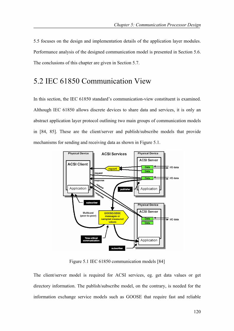
in [84, 85]. These are the client/server and publish/subscribe models that provide
mechanisms for sending and receiving data as shown in Figure 5.1.
Figure 5.1 IEC 61850 communication models [84]
The client/server model is required for ACSI services, eg. get data values or get
directory information. The publish/subscribe model, on the contrary, is needed for the
information exchange service models such as GOOSE that require fast and reliable

Chapter 5: Communication Processor Design
121
transmission of data to multiple receivers. Finally, the reporting model makes use of a
one-way communication model that involves transmission of the available reports to
ACSI clients making use of their IP addresses.
IEC 61850 defines abstract data and object models as a standardised method of power
system device description enabling data to be described using identical structures. The
IEC 61850 ACSI models are set of services and responses to these services that regulate
identical network behaviour for all IEDs. Although the abstract models are an important
step towards interoperability, they can only be usable when operated over a set of real
protocols. The IEC 61850 standard describes this in IEC 61850-8-1 [76] as the Specific
Communication Service Mapping (SCSM) on specific communication services such as
the MMS and ISO/IEC 8802-3 as shown in Figure 5.2 [11].
Figure 5.2 IEC 61850 communication profiles [11]
In this research, a standard Object Oriented (OO) implementation of the ACSI OSMs
was accomplished as described in Chapters 3 and 4. Although the latter eliminated the
need for the mapping process, ACSI OSMs do not themselves provide the required
Chapter 5: Communication Processor Design
122
communication models. Consequently, there still existed the need for a data delivery
network middleware architecture to be designed for serving the special communication
requirements of the IEC 61850 standard such as the need to support:
1. Client/server communication model,
2. Publish/subscribe communication model,
3. Fine grained time synchronisation [106],
4. The ability to trade off delivery reliability against delivery delay [54], and
5. The ability to identify differing Quality of Service (QoS) requirements of the
different message types supported by the application layer.
The designed middleware had to be small and fast adding only minimal overhead to the
underlying network communication stack. Furthermore, it needed to be much more
efficient than MMS or CORBA. Although MMS preserves many technical advantages,
it has not been completely successful. Main criticism to the MMS architecture includes
the complexity; poor performance and lack of any explicit support for publish/subscribe
architectures. The latter item explains the reason why a second communication stack,
the ISO/IEC 8802-3, had to be proposed in [76] for the mappings of peer-to-peer
communication capability requiring models such as the GOOSE.
Clearly, there were many challenges such as aforesaid, which had to be solved.
However, the need to design a real-time communication model to run with a
communication processor was evident. The term “real-time” means that an application
should respond to events within a prescribed range of time even under failure and
extreme load conditions. Overall, the real-time communication model had to support the
following features:
Chapter 5: Communication Processor Design
123
• Support for the client/server communication model,
• Support for the publish/subscribe communication model,
• Modelling time and time-stamping each transaction [54],
• Allowing for the trade-off between delivery delay and reliability [54],
• Working in a real-time communication processor environment [54],
• Support for the different QoS requirements.
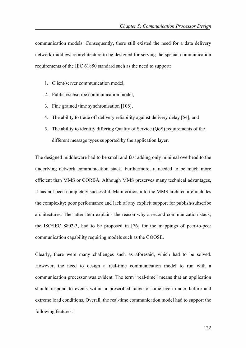
5.3 The Proposed Model The overall architecture of the proposed communication processor is shown in Figure
5.3. On the network access side of the communication processor protocol stack, an
Ethernet based Internet network is utilised offering different levels of guarantees for
network performance such as fast delivery times or guaranteed delivery.
IEC 61850 Client IEC 61850 Server
Middleware
Network Access
Middleware
Network Access
Network
Sta
nd
ard
Wo
ksta
tion
Figure 5.3 The overall communication processor architecture
On the application side, the designed communication processor contains an application
layer module where ACSI applications can be configured. The application layer
processor can be modelled either as an ACSI server or an ACSI client. The modelling of
Chapter 5: Communication Processor Design
124
an ACSI server has to be carried out making use of the C++ class and service
descriptions developed in Chapters 3 and 4. This clarifies the reason behind the need for
the OO implementation of ACSI OSMs so that they can be used in the process of
implementing various representations of real devices at the application layer.
An end-system based middleware, which decouples applications from network
processes, is located between the network access and application layers as shown in
Figure 5.3. The designed middleware, IEC-MOM, does not provide any object or
service models but only message distribution mechanisms. It uses the principles of
MOM for timely message delivery across the network [107-109]. MOM is based on the
model of message passing or queuing between a sender and a receiver. One of the most
important principles of MOM is message queuing [110], which provides strong
reliability guarantees in case of failure by storing messages on disk. Originally, MOMs
used to have only client/server architectures. Yet, nowadays they have been extended to
include publish/subscribe features as well. This is one of the most significant features of
the IEC-MOM middleware that helps to eliminate the need and disadvantages that arose
from the use of multiple communication stacks as illustrated in Figure 5.2.
IEC-MOM operates above the TCP-UDP/IP stack and provides a single common
interface to all IEC 61850 profiles including core ACSI services, GOOSE and SV. The
TCP/IP stack is used for the core ACSI services whereas the UDP/IP stack is utilised for
the GOOSE and SV profiles. IEC-MOM enables applications to exchange messages
with other applications without having to know what kind of platform the other
application resides on, thus increasing the flexibility of the whole architecture. The
following sub-sections describe the individual features of the IEC-MOM middleware.

Chapter 5: Communication Processor Design
125
5.3.1 The Client/Server Communication Model
This sub-section covers various aspects of the client/server communication model of the
designed middleware. The client/server is based on MOM’s asynchronous message
passing between a client and a server application as demonstrated in Figure 5.4.
Asynchronous means that the client application will not be blocked until server’s
response arrives and it can continue to issue requests to other applications. In contrast to
synchronous mechanisms employed by Remote Procedure Call (RPC) [111, 112], an
infrastructure type attempted earlier on in [113, 114], the use of an asynchronous
request-reply mechanism in MOM does not require the client and server to be available
all the time. If the destination application is unavailable or busy, the messages will be
held in a temporary store location, a message queue, until they can be processed.
Client Application Server Application
IEC-MOM IEC-MOM
ServerObject (e.g
LogicalNode 1)
Server Object (e.g LogicalNode n or DATA)
Request Confirm
Communication Services
Response Indication
Communication Services
Communication Stack/ Profile
Figure 5.4 Interaction between a client and a server
The client/server communication model is used for transferring messages that originate
at the application layer due to service requests such as get data values or get data
directory information, etc. Such services require a communication processor to receive
every step in the command sequence properly, which can only be guaranteed with
reliable delivery. One of the fundamental advantages of the asynchronous client/server

Chapter 5: Communication Processor Design
126
MOM is reliable message delivery through the use of message queues [115]. The use of
the TCP protocol, which is very popular for its reliable transmission, for such messages
further supports the quarantined delivery of messages.
TCP is a connection-oriented transport layer protocol that requires the name of the
destination node when establishing an application session with that node. Hence, the IP
addresses must always be included in the request-reply messages originating from the
application layer. This is not a major concern since in IEC 61850 applications, the
communicating nodes are required to be aware of the names of the destination nodes
with which they need to communicate. The IEC-MOM middleware makes use of these
IP addresses when establishing connections with the destination nodes.
5.3.2 The Publish/Subscribe Communication Model
This sub-section covers various aspects of the publish/subscribe communication model
of the designed communication processor. It focuses on the design constraints behind
the design of a suitable real-time publish/subscribe model for substation communication
systems. The publish/subscribe communication model is basically an added feature to
the client/server model formerly described. The main difference is that multicast group
addresses are used instead of IP addresses. In this section, design issues are described
for successfully distributing mission and time critical information within the substations
to legitimate parties in a timely, reliable and accurate manner. A number of issues need
to be considered simultaneously when building an appropriate publish/subscribe
communication model. These involve the choice of a suitable routing mechanism and a
number of techniques for the tasks of binding, filtering and making subscriptions.

Chapter 5: Communication Processor Design
127
5.3.2.1 The routing problem The main approaches for solving the routing problem are:
1) Sending a number of points to point messages,
2) Sending a multicast message, and
3) Sending a broadcast message.
GOOSE and SV are the main profiles requiring indirect peer-to-peer asynchronous
delivery. The IEC 61850 standard has specified the use of the multicast alternative,
shown in Figure 5.5, for this purpose.
Sending Host
1 2 3 4 5 6
7 8 91 01 112
AB
1 2x
6x
8 x
2 x
9x
3x
1 0x
4 x
11 x
5x
7x
1x
Eth
erne
t
A
1 2x
6x
8 x
2 x
9x
3x
10 x
4x
11 x
5x
7x
1x
C
Ethernet Hub
Receiving Device Receiving Device Receiving Device
1 2 3 4 5 6
7 8 9 101 11 2
AB
1 2x
6x
8x
2x
9x
3x
1 0x
4x
11x
5x
7x
1x
Ethe
rnet
A
12 x
6x
8x
2x
9 x
3 x
1 0x
4x
11 x
5 x
7 x
1 x
C
1 2 3 4 5 6
7 8 9 10 111 2
AB
12 x
6x
8x
2x
9 x
3 x
10 x
4x
1 1x
5 x
7 x
1 x
Eth
ern
et
A
12 x
6 x
8x
2x
9 x
3 x
10 x
4 x
1 1x
5 x
7 x
1 x
C
Another subnet
1 2 3 4 5 6
7 8 9 1 01112
AB
12 x
6 x
8 x
2 x
9x
3x
10 x
4 x
11 x
5x
7x
1x
Eth
erne
t
A
1 2x
6 x
8 x
2 x
9x
3x
10x
4 x
11 x
5x
7x
1x
C
Another subnet
Receiver not interested in the multicastdoes not receive it
Figure 5.5 Multicast transmission
Multicast represents a unidirectional and connectionless communication between a
server and a selected set of clients as defined in IEC 61850. The multicast concept is
crucial for power system applications in which a given analogue value, state change, or
command may be communicated to several peers at the same time. Multicast messaging

Chapter 5: Communication Processor Design
128
[116, 117] allows the sender to send a single copy to the data stream, which will then be
replicated by switches or routers and forwarded to receivers that have previously
signalled their interest in that message. Receivers, also called subscribers, indicate their
interest by joining a particular multicast session group. The key advantage of multicast
messaging is that it reduces the amount of traffic over the network yielding an increased
efficiency for both the publisher and network with a number of other key performance
improvements. Multicast oriented communication enables nodes to join or leave groups
as a local activity unambiguously creating group membership and group wide
awareness.
The major disadvantage concerned with multicast transmission, on the other hand, is the
fact that it can be unreliable. However, it is possible to multicast GOOSE and SV
messages due to the fact that they can be repeated a number of times until their time-to-
live expire to achieve higher reliability and they need not to be acknowledged.
5.3.2.2. The subscription mechanism In ACSI, GOOSE messages are put forward as a means of expressing all required
protection scheme information of an individual protection IED. The status of the
functional elements in an IED is reported in the form of a state machine. Once IEDs
capture the effects of abnormal system conditions within a substation, they express the
details in the form of GOOSE messages. The power quality monitoring and recording
devices are the type of devices that are usually interested in receiving such GOOSE
messages [82]. However, in order to receive such messages, they need to have a
mechanism for registering and subscribing to the publishing device’s multicast group.
This suggests that each subscribing device needs to be aware of its publishers and their

Chapter 5: Communication Processor Design
129
relative IP Multicast Group Addresses (MGAs). Figure 5.6 shows a distribution feeder
protection relay, the PIED, publishing to a subscribing device that is a power quality
monitoring and recording (PQMR) IED. When the feeder detects a fault, it will trigger
the operation of the PQMR by sending a multicast message to various destinations
including the PQMR itself.
Figure 5.6 Feeder IED publishing to the subscribing IED [82]
Reference [54] discusses that each publishing node must not only be aware of its own
subscribers but also a complete list of publishers each one of its subscribers subscribes
to. Similarly, reference [54] also states that in the case of a subscribing node, each
subscriber needs to be aware of its own publishers and a complete list of the subscribers
each one of its publishers publishes to.
The designed real-time publish/subscribe model associates a logical handle to each
publishing device. The logical handle can simply be a variable length ASCII string
containing the address and name of each publishing device and names of its subscribers.
Each subscriber interested in receiving GOOSE messages from a particular publisher
needs to subscribe itself in the “subscribers” list of the publishing device with a
subscription message containing its name, address and the names of the other devices it

Chapter 5: Communication Processor Design
130
has subscribed to. Thus, each publisher will have a list of its own subscribers and a list
of the other publishers they have subscribed to as stated as a necessity in reference [54].
Each published GOOSE message will be tagged with the logical handle information of
its publisher. Subscribers upon receiving GOOSE messages will be able to filter the
logical handle to acquire the name and address of the publisher as well as the list of
subscribers it publishes to. The subscribers will then be able to keep a record of not just
their publishers but also a list of the other subscribers that subscribe to same publishers.
5.3.2.3. Binding and filtering The problem of binding can be overcome very easily by using the publisher-based
subscription mechanism. Publisher-based subscription mechanism requires subscribers
to subscribe to publishers providing their details such as node name, node address and
protocol etc. Once a subscription is processed, a publisher will add the relative
subscriber into its “subscribers” list. When a GOOSE message becomes available at the
publisher, it can be multicast to all the subscribers by the source making use of the IP
MGA instead of individual subscriber addresses. However, since the GOOSE message
is to be tagged with a logical handle, the task of binding includes the processing of the
subscriptions in order to fetch the subscriber addresses forming a “subscribers” list to
accompany the GOOSE message. This has to be repeated before the delivery of every
GOOSE message updating the list of subscribers taking into account the possibility of
new subscriptions and unsubscriptions.
While binding takes place at the publisher, filtering needs to be carried out at each
subscriber to filter out unwanted messages. Although the possibility of receiving
unsubscribed GOOSE messages at the subscriber is quite low, it would still be desirable

Chapter 5: Communication Processor Design
131
to include a filtering mechanism. The relative overhead of the filtering is quite small
when the publisher-based subscription mechanism is used. Each GOOSE message is
tagged with a logical handle, which includes information about its publisher. The
complexity of the filter and hence the overhead will be reduced since the filter only
needs to evaluate the logical handle rather than the whole message content. The
evaluation of the logical handle includes matching the publisher’s name with one of the
names in the subscriber’s list of publishers. If a match is found, then the message will be
accepted and processed. Otherwise, the message will be rejected and destroyed.
5.3.2.4 QoS
Publish/subscribe systems usually address mechanisms for message ordering and
reliability of message delivery. One such example is “Priority Queuing”. Priority
queuing uses multiple queues as shown in Figure 5.7, which are serviced with different
priority levels.
Figure 5.7 Priority queuing [118]
As depicted in Figure 5.7, the highest priority queue containing the highest priority
messages is usually serviced first. In the case of any congestion, packets residing in the
Chapter 5: Communication Processor Design
132
lower priority queues will be dropped [118]. This kind of queuing is perfectly suitable
for the delivery of GOOSE state change messages, which are certainly to have the
highest priority level on a substation network. Therefore, priority queuing along with an
appropriate scheduling mechanism is beneficial in the publish/subscribe communication
model that needs to be designed for substation communications. Besides the use of
congestion management mechanisms such as priority queuing, the use of congestion
prevention mechanisms such as the Weighted Random Early Detection (WRED) [119]
for congestion avoidance is also favourable. WRED prevents congestion by starting to
drop low priority packets only in the case of a future congestion detection to ensure the
delivery of mission critical messages such as GOOSE messages.
In this research, the synchronised use of the User Datagram Protocol (UDP) and the
Resource Reservation Protocol (RSVP) [120] is proposed to satisfy the most important
QoS parameter concerned with the delivery of GOOSE messages, which is the
maximum application-to-application delay requirement of 4 ms [121, 122]. The 4 ms
delivery delay requirement implies that the total delivery delay between the
communicating devices should not exceed 4 ms. It includes the delay on the wire as
well as the delay the message encounters while travelling through the protocol stack
from the application layer all the way to the hardware [122].
According to the published IEC 61850 standard, GOOSE and SV profiles do not use the
ISO network layers UDP/IP as illustrated in Figure 5.2. However, in this research, the
use of the UDP/IP stack is seen as a benefit. The main criticism to this decision is high
likely to include the fact that GOOSE and SV messages will be introduced to extra
delays when passing through these layers. Although correct, this delay is relatively

Chapter 5: Communication Processor Design
133
small and will not exterminate the 4 ms timing determinism. Moreover, considering the
advantages gained from the use of the UDP/IP stack, this decision can be justified. UDP
is a connectionless transport layer protocol, which has a very fast response time and a
very low overhead. It is well suited for real-time applications where messages can be
multicast efficiently and datagram boundaries are respected. The greatest advantage of
utilizing IP is that security and encryption can be built into the communications. The IP
multicasting technology has been proven over the years and presents many advantages
to the users. One such example is the fact that it is well optimised and packets are only
sent to the routers that need them. In addition, using the RSVP protocol, each publisher
can easily specify the upper bound of the delay, which in the case of GOOSE messages
will be 4 ms. Once the specifications are given, then the delivery of GOOSE messages
takes place taking the traffic specification into consideration at every step along the
network.
However, the mechanisms described above are not adequate when addressing some
other issues concerned with substation communication systems. With the synchronised
use of UDP and RSVP, it is quite possible to satisfy the 4 ms delay condition. However,
the reliability of messages becomes a major concern in this case since UDP cannot
provide reliable messaging at all. There is a different interpretation in substations for the
relationship between reliability and delivery delay. Timely and reliable transmission of
messages implies that GOOSE messages need to be repeated in the case of failures until
their hold time expires whilst not exceeding the 4 ms application-to-application delay
criteria. This can be achieved by a mechanism, which trades off delivery delay against
delivery reliability. What is needed is a guaranteed delivery mechanism operating above
the level of the UDP transport protocol. Such a mechanism running above UDP will be

Chapter 5: Communication Processor Design
134
superior to TCP since it will prevent the uncontrollable communication latency that
results in the case of TCP. Moreover, by limiting the number of re-transmissions, the
necessary trade-off can be achieved since UDP will not get stuck trying to re-transmit
the messages forever destroying the timing determinism completely.
5.4 The Design and Implementation of the IEC-MOM middleware
This section focuses on the architectural design and implementation of the IEC-MOM
middleware. First, the architectural overview of the middleware is given followed by its
implementation details.
5.4.1 IEC-MOM Architectural Overview Figure 5.8 depicts the detailed architectural overview of the IEC-MOM middleware.
Sending Application Receiving Application
IEC-MOM
Network
InterruptsManager
Queue Manager
Transmission subqueues
DeliveryManager
Connection ManagerTPAL
Transport & Network LayerData Link & Physical Layer
Network Interface
IEC-MOM Delivery Manager
Interrupts ManagerTPAL
Transport & Network LayerData Link & Physical Layer
Network Interface
QueueManager
Applicationsubqueue
Msg Msg
Msg Msg
Figure 5.8 IEC-MOM architecture
Chapter 5: Communication Processor Design
135
The middleware layer consists of several components such as Interrupts Manager,
Queue Manager, Connection Manager and Delivery Manager. These components take
care of many communication details and handle the interaction of IEC 61850
applications. The tasks of the individual components are described below:
Interrupts Manager: The interrupts manager is responsible for receiving interrupts and
determining their type when the middleware module is interrupted as a result of a new
event. For example, the arrival of a new message (packet) at the input stream of the
middleware module triggers a stream interrupt. In such cases, the interrupts manager
needs to detect whether the packet is an application layer or a transport layer packet. If
the packet is coming from the application layer, then it will be forwarded to the queue
manager of the transmission queue. Otherwise, it will be forwarded to the queue
manager of the application queue.
Queue Manager: The queue manager is responsible for associating an incoming packet
with an appropriate queue. It is possible to define a number of internal subqueues in
which packets can be inserted and sorted, and from which packets can be extracted for
transmission according to a general user-defined method. If the arriving packet is from
the transport layer, it will be stored in the application subqueue that contains packets
headed to the application layer. However, if the packet is from the application layer,
then queue manager decodes the packet in order to determine its type. Three subqueues
have been reserved for messages arriving from the application layer: subqueue 1 for
GOOSE Messages, subqueue 2 for SV messages and subqueue 3 for the remainder
including service requests and reports. The vital aim here is to assign different priority
levels to the subqueues to make sure that highest priority messages are serviced first.

Chapter 5: Communication Processor Design
136
Rationally, in this project, the highest priority has been assigned to subqueue 1, then
subqueue 2 with subqueue 3 having the least priority. Once the newly arrived packet is
inserted into the relevant subqueue, then the queue manager hands of the control to the
delivery manager.
Delivery Manager: The delivery manager is responsible for handling the flow of
messages in the IEC-MOM module. As soon as the control is passed to the delivery
manager, it starts removing messages from the subqueues beginning from subqueue 1.
As soon as all the messages in subqueue 1 have been catered for, it moves on with
subqueue 2 and so on. Besides removing messages from the subqueues, the delivery
manager is also responsible for creating and invoking a new transport mechanism thread
(connection manager) for each removed message.
The use of a dedicated transport mechanism thread for each individual message is much
useful in stopping problems that arise during the delivery of a single message from
affecting the transmission of other messages. Whilst the connection manager is being
invoked, a number of transmission specific details are passed to the connection manager
along with the original message. Such information includes:
1 The application service name,
2 The transport protocol to be used ,
3 Whether the transmission needs to be unicast or multicast, and
4 Type of service (TOS) and RSVP parameters.
Therefore, for each message, the delivery manager informs the connection manager
about the constraints to be used when establishing a connection. For example, for

Chapter 5: Communication Processor Design
137
GOOSE messages from subqueue 1, the delivery manager sets the application service
name as “GOOSE Messaging” and indicates that a multicast session needs to be
established using the UDP transport protocol. The TOS and RSVP parameters will be
set to their highest priority/best effort values since GOOSE messages require highly
deterministic delivery.
The delivery manager follows two different approaches to maintain the reliable delivery
of messages. Undelivered service request from subqueue 3 will be reinserted into
subqueue 3 by the delivery manager and their priorities will be increased. It is also
possible to assign different priorities to messages within the same subqueue and then
sort the subqueue based on increasing priority. On the other hand, for GOOSE messages
from subqueue 1, a delivery delay against delivery reliability trade-off mechanism is
utilised. It simply involves the invocation of a number of transport mechanism threads
for the same GOOSE message at different intervals given by the following formulae
until a maximum delay time of 4 ms is reached.
)1.5(0001.0)1( 1 equationnt R ×+= −
where t is the delay time, in milliseconds, between the successive retransmissions, n is a
setting between two and seven inclusive while R is the sequential repeat number of the
message [123]. For example, when a setting number (n) of five is used, the delay
between the first event-driven message and the second retransmission is 0.6 ms.
The whole process is much simpler for the application subqueue messages. In that case,
the delivery manager simply removes messages from the application subqueue and
forwards them to the application layer module. There is no need for any reliability

Chapter 5: Communication Processor Design
138
concern in this case since the likelihood of a message being unsuccessfully transmitted
between two modules in the same processor is extremely low.
Connection Manager: The connection manager or otherwise called the transport
mechanism thread manages the unicast and multicast transmissions. It is basically used
for opening a connection with the underlying Transport Protocol Application Layer
(TPAL) to start an application. While establishing the connection, all the constraints
regarding the transmission of the message will be forwarded to the TPAL layer. TPAL
is a basic and uniform interface between the middleware layer and different transport
protocols. It establishes a connection with the transport protocol specified by the
connection manager virtually linking the middleware module with the specified
protocol. Once TPAL gives “OPEN” confirmation, the packet received from the
delivery manager will be sent to TPAL to be forwarded to the chosen transport protocol.
5.4.2 IEC-MOM Implementation
Software based implementation of the IEC-MOM middleware was carried out by using
the OPNET Modeller from MIL3. OPNET [124] is an object-oriented simulator that
allows for modelling, simulating and analysing the performance of communication
networks, computer systems, applications and distributed systems. It contains a set of
networking protocols and analysis environments such as:
1 Client-Server Analysis Environment,
2 Transmission Control Protocol (TCP),
3 User Datagram Protocol (UDP), and
4 Internet protocol (IP).

Chapter 5: Communication Processor Design
139
It also contains many tools for designing and collecting data on network models such as:
1 Network Editor (creating network model),
2 Node Editor (creating node models),
3 Process Editor (creating process models), and
4 Analysis Tool (analysing simulation results).
The IEC-MOM middleware has been implemented in a queue module between the
TPAL and application layers of a communication processor as shown in Figure 5.9.
Figure 5.9 Communication processor node model
Figure 5.9 shows the general node model of a communication processor. A node model
is a collection of modules representing district functional areas of the node. The use of a
queue module for the IEC-MOM middleware allows for the creation of subqueues in
which packets can be stored in an organised manner for later use. In OPNET, process

Chapter 5: Communication Processor Design
140
models are used to specify the behaviour of processor and queue modules that exit in
the node domain. An individual process or groups of processes implement a particular
task when placed in a process model. A single process is an instance of a process model
defined within the process editor. Figure 5.10 shows the process model of the queue
module that was used to implement the behaviour model of the IEC-MOM middleware.
Figure 5.10 Process model of the IEC-MOM middleware module
OPNET process editor provides a powerful and efficient method based on State
Transition Diagrams (STDs) for describing the behaviour of discrete event systems.
STDs, also referred to as Finite State Machines (FSMs), are used in specifying and
developing a wide range of software and hardware systems. A STD consists of two
basic component types: states and transitions as illustrated in Figure 5.10. States
represent top-level modes that a process can enter. Transitions show the possible state
changes of the process. The IEC-MOM STD consists of 4 states and transitions between
these as illustrated in Figure 5.10. The description of each state is provided below
examining the tasks performed in each state.

Chapter 5: Communication Processor Design
141
• Init State: The main task performed in this state is the initialisation of the
process model of the IEC-MOM middleware module. After the initialisation of
the lower layers is completed, the “Init” state schedules an interrupt in order to
perform the initialisation of the middleware module. OPNET processes are
event-driven. An interrupt is a terminology given to an event that is actually
delivered to a process. Most transitions between states occur once a certain
interrupt is received. The process remains in the “Init” state until a confirmation
is received indicating the completion of the initialisation process after which the
process proceeds to the next stage that is the “Start” state.
• Start State: The main tasks performed in this state include initialisation of all
the state variables used by this process model as well as service registration.
Service registration is the act of issuing a service registration command to TPAL
for each supported service. A service registration command basically includes
the name of the service, the protocol and port index through which it can be
accessed. Examples of services, an IEC 61850 node may support, include the
transmission of GOOSE, SV and service request messages. Besides the tasks
described above, the statistics that are maintained by this process model are also
registered in this state. Once all this tasks are accomplished, the process
proceeds to the “Idle” state.
• Idle State: The interrupts manager is the sole component running in this state.
The functions of the interrupts manager were previously described in detail. The
IEC-MOM process model stays in the “Idle” state until a stream interrupt is
received triggered by the arrival of a new packet. If the received packet is

Chapter 5: Communication Processor Design
142
coming from the TPAL layer, the process proceeds to the “RECEIVE” state.
Otherwise, it proceeds to the “SEND” sate.
• RECEIVE State: The main components running in this state are the queue
manager of the application subqueue and the delivery manager. The queue
manager inserts the packets arriving from the TPAL layer into the application
subqueue. The packets are shortly removed from the application subqueue one
by one by the delivery manager to be processed and forwarded to the application
layer. After all the packets in the application subqueue are removed and
forwarded to the application layer, the process proceeds back to the “Idle” state.
• SEND State: The queue manager of the transmission subqueues and the
delivery manager are the main components running in this state. The queue
manager processes the incoming packets from the application layer inserting
them into the relevant subqueue based on their type. The delivery manager
removes all the packets from the transmission subqueues starting from the
highest priority one. For each message, it creates and invokes a new connection
manager thread running in the child process model shown in Figure 5.11 passing
the transmission specific requirements to the thread along with the original
message. Once all the packets in the transmission subqueues have been catered
for, the process proceeds back to the “Idle” state.
Figure 5.11 IEC-MOM child process model

Chapter 5: Communication Processor Design
143
The process model shown in Figure 5.11 is referred to a child process with respect to
the process model that creates it. The use of a separate child process for the connection
manager is useful in stopping the failure of a single transport mechanism thread from
affecting the parent process. The connection manager running in the child process
establishes a TPAL connection and sends the packet to the TPAL module subsequent to
receiving an “OPEN” confirmation. These actions are all carried out in the “open” state.
If the connection manager fails to receive an open confirmation from TPAL for the
service request messages (core ACSI services), the packet will be reinserted into
subqueue 3. The connection manager closes the TPAL connection in the “close” state
where the child process also terminates itself.
5.5 The Design and Implementation of the Application Layer Modules
This section focuses on the architectural design and implementation of two different
application layer models. The first application layer model has been designed as a
module where ACSI servers can be configured whilst the second for the configuration
of ACSI clients. The application layer is the seventh layer of the seven-layer OSI model.
Common application services for the application processes are performed in this layer.
5.5.1 Server Application Layer Design and Implementation
In this sub-section, the architectural design of a standard application layer module built
on top of IP-TCP/UDP, where ACSI servers and virtual representations of real devices
can be configured, is proposed and described in detail. The core ACSI services using the
client/server communication model do not require any complex mechanisms. It is

Chapter 5: Communication Processor Design
144
sufficient that the requesting node knows about the IP address of the destination node.
However, this is not the case for the publish/subscribe communication model requiring
information exchange service models such as GOOSE. The success of these services
relies on the ordered use of mechanisms for the tasks of registering, binding, filtering
and making subscriptions. The key behind the design of the real-time publish/subscribe
communication model can be briefly summarized as follows. Non-real time activities
such as getting publication or subscription rights happen outside the real time loop
ideally at the start-up. Conversely, the generation, transfer and reception of messages
are real-time activities happening in the real-time loop requiring very fast response
times. There are two types of nodes. Subscriber nodes can only subscribe to messages
whereas “publisher-subscriber” nodes can publish messages as well as subscribe to
messages published by other nodes. The following sub-sections describe how the tasks
of registering, binding, filtering and making subscriptions are accomplished at the
server application layer module. The architectural components, which play part in the
carrying out of these tasks and others including the sending, reception and execution of
IEC 61850 associated messages, are also described.
5.5.1.1 Registering Ideally at the start-up, each publishing node must be associated to a multicast group
each having a unique label, which is referred to as the IP Multicast Group Address
(MGA). The Multicast Membership Service (MltcMS) is responsible for storing IP
MGAs. Entries within the MltcMS contain publishers’ IP host names and MGAs.
Various nodes on the network communicate with the MltcMS to create/delete entries
and to add/delete their publication/subscription rights.
Chapter 5: Communication Processor Design
145
A node interested in publishing messages gets its publication right by creating an entry
in the MltcMS’s IP MGAs table. On the other hand, those nodes interested in receiving
messages from a particular publisher have to make use of the publisher’s IP MGA in
order to join themselves to the multicast group associated with that publisher. This is
referred to as registering. Any node interested in subscribing to messages gets its
subscription right by retrieving the IP MGA for the multicast group it seeks to join from
the MltcMS. Once the subscriber obtains the IP MGA, it can complete its registration
and join a multicast group by following the subsequent sequence:
1. The registry manager process running within the subscriber joins a multicast group,
Group 1, by sending a join request to its IP module using a remote interrupt,
2. The IP module forwards an IGMP membership report message to the neighbouring
multicast router, and
3. The multicast router sets up a distribution tree for Group 1 adding the interface
details of the joining subscriber so that it can receive packets sent to Group 1.
5.5.1.2 Subscription, binding and filtering Registering has to be followed with a subscription request sent to the relevant publisher.
It should be kept in mind that registering basically serves the purpose of setting up a
distribution tree for each multicast group within the multicast router. In applications
where publishers need not to be aware of their subscribers, the process of registering is
by itself adequate. However, as indicated previously, each publisher in a substation
network is required to hold detailed information related to its subscribers. Thus, the
mechanism of sending subscription requests and receiving confirmation messages in
return has been designed and implemented in this project in order to solve this problem.

Chapter 5: Communication Processor Design
146
Subscription requests are sent immediately after the subscriber registers for any
multicast group. One subscription request has to be sent to each one of the publishers.
A subscription request is no more than a packet containing a number of fields. By
setting the fields of a subscription request, a subscriber can inform any publisher over
the network about its own local details such as the node name and IP address in addition
to information specifying whether it wants to subscribe for GOOSE and/or MSVCB
messages produced by that node. Hence, a combined approach of publisher and subject
based subscription mechanism has been adopted, which has a number of advantages
when used in conjunction with the registering process.
Strictly speaking, the task of binding in publishers is unnecessary since each publisher
uses a Multicast Group Address to publish its messages. However, each publisher still
produces a list of its own subscribers to be tagged onto the outgoing multicast message.
This serves two purposes. First of all, such a list can be cross-examined by the router
against its own registry list reducing the possibility of unwanted messages from being
sent to nodes showing no interest in them. Secondly, when a multicast message reaches
its destination, the subscriber can access to the tagged information and store the names
of the other subscribers that subscribe to the same publisher as required in substation
applications. Similarly, the task of filtering can also be fully avoided since after all the
measures taken, the chances of an unwanted message reaching at any node is fairly low.
However, with the intention of being precautious, a fairly simple filtering process has
been implemented that checks the source of messages comparing it to the entries in the
node’s list of publishers. In cases where a match can not be found, the packet will
simply be destroyed.

Chapter 5: Communication Processor Design
147
Data
Publisher Subscriber
IEC-MOM
Real-Time OS
Delivery Manager
Registry Manager
ACSI Configuration Manager
My Publishers /Subscribers list
Node Node
Node Node
Network
MltcMS
Operations Membership
Execution Manager
5.5.1.3 Architectural components Figure 5.12 depicts the detailed architectural overview of the server application layer
module. Such a model is appropriate and efficient for client/server requests as well as
periodic and synchronous updates between sources and sinks. It exclusively supports the
publish/subscribe model as it makes use of the previously discussed mechanisms.
Figure 5.12 Architectural components of the ACSI server application layer module
The following sequence of events occurs when a source (publisher) pushes multicast
packets out of its output interface destined for a particular multicast group:
Local Manager

Chapter 5: Communication Processor Design
148
1. The application running within the source multicasts a packet using the Multicast
Group Address (MGA) that is also referred to as the multicast membership address,
2. When the packet reaches its rendezvous point (IP address of the router responsible
for distributing multicast traffic to the specified multicast group), the router’s IP
process forwards the multicast packet to the “ip_pim_sm” process, and
3. The “ip_pim_sm” process is one of the child processes of the IP module, which
makes multiple copies of the multicast data and sends one copy to each one of the
subscribers listed in the multicast route table.
All the architectural components shown in Figure 5.12 assist in the successful operation
of the application layer communication model in one way or another. An individual
discussion for each one of the architectural components is provided below:
Local Manager: Local manager executing in every publisher and subscriber is
responsible for the creation/deletion of publication or subscription rights. One of the
tasks of the local manager is to periodically update its “multicast membership
addresses” list based on the periodic info received from the MltcMS regarding the status
of the publication/subscription rights.
Registry Manager: Subscribers interested in joining any multicast session group do
this with the help of the registry manager, which simply contacts the IP module
expressing the subscriber’s interest in joining a multicast session group. Registry
manager also handles the process of sending subscription requests. In cases where
publishers subscribe to other publishers’ multicast session groups, it also performs the
task of updating the “publishers” component of the MyPublishersSubscribers list.

Chapter 5: Communication Processor Design
149
Execution Manager: Execution manager is responsible for determining the type of the
packet arriving from the IEC-MOM middleware module. After it determines the type of
the packet, it executes the relevant packet execution/destroy mechanism. Examples of
the packet types expected at an ACSI server application layer include reports, GOOSE
messages, ACSI service requests, GOOSE or MSVCB subscription requests, MSV
messages and etc. Individual packet execution/destroy mechanisms have been designed
and implemented for various packet types. The packet execution/destroy mechanism are
mainly used for accessing the relevant fields of the received packet obtaining the
information stored within its fields. Once this is concluded, they execute a response
based on the information acquired. For example, in the case of service requests received
from ACSI clients, the information stored within the packet include the name of the
service to be performed and input parameters to be passed to the service. The ACSI
service request execution/destroy mechanism accesses this information executing the
relevant service with the input parameters received in the request. The names and
possible input parameters of ACSI services were previously covered in Chapters 3 and
4. After the packet is executed, the packet execution/destroy mechanism updates a
number of statistics such as the application-to-application delay statistic of the packet
before destroying it.
Delivery Manager: The delivery manager thread is executed shortly after the execution
of a service request received from an ACSI client. Each service request needs to return a
reply back to the calling client. This task is accomplished by the delivery manager,
which creates and sets the fields of a reply packet headed to the requesting client. All
the output parameters returned by the executed service are inserted into the same packet
along with a timestamp designating the current time and date.
Chapter 5: Communication Processor Design
150
ACSI Configuration Manager: The ACSI configuration manager basically acts as a
device parameter configuration tool. It is mainly used for configuring an ACSI server at
the server application layer module. Substation configuration describes which of the
optional information is used in a specific device, what the instance names of all LNs
are. IEC 61850-6 has specified a description language for the configuration of electrical
substation IEDs. This language is called the Substation Configuration Description
Language (SCL), which is based on the XML schema language. However, in this study,
the SCL has not been utilised. Instead, the LNs, LDs, data and data attributes as well as
the services used and provided by an IED are configured utilising the C++ programs
described in Chapters 3 and 4.
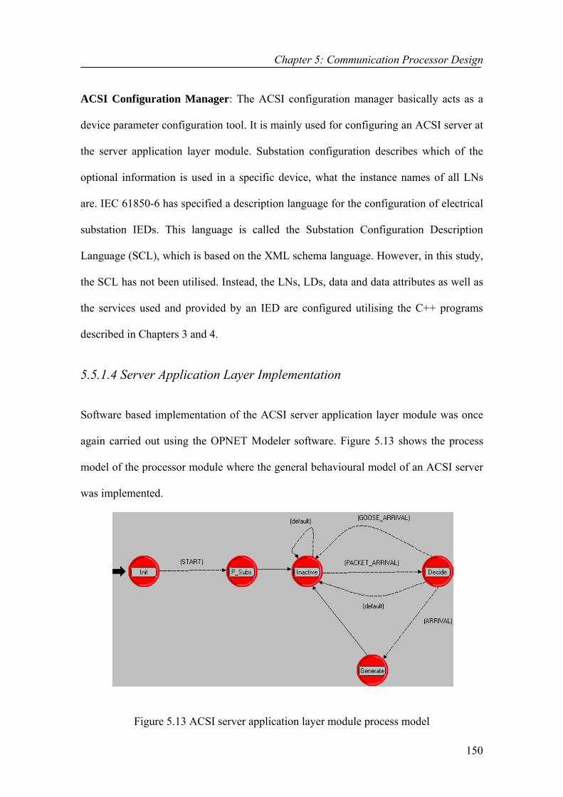
5.5.1.4 Server Application Layer Implementation
Software based implementation of the ACSI server application layer module was once
again carried out using the OPNET Modeler software. Figure 5.13 shows the process
model of the processor module where the general behavioural model of an ACSI server
was implemented.
Figure 5.13 ACSI server application layer module process model

Chapter 5: Communication Processor Design
151
Processor modules are the primary building blocks of node models. They can be
connected to other modules via a number of packet streams. They can act as traffic
generators and/or sinks. As illustrated, the STD of the server application layer module
consists of 5 states and transitions between these. The actions performed in each state
are listed below:
• Init State: The ACSI configuration manager and the local manager are the two
components executing in the “Init” state. The ACSI configuration manager
configures an ACSI server whilst the local manager updates the “multicast
membership addresses” list of the node with the information it receives from the
MltcMS. The state variables used by this process model are also initialised in
this state. The process proceeds to the “P_Subs” state once all these tasks are
accomplished.
• P_Subs State: Registry manager is the sole component executing in the
“P_Subs” state. It carries out the registering and sends subscription requests to
the publisher nodes.
• Inactive State: The process stays in the “Inactive” state until a stream interrupt
is received triggered by the arrival of a new packet. Only then, the process
model proceeds to the “Decide” state.
• Decide State: Execution manager is the main component running in this state. It
determines the type of the received packet and calls the relevant packet
destroy/execution mechanism. If the packet is a service request message, the
process proceeds to the “Generate” state. Otherwise, for all other message types,
it defaults back to the “Inactive” state where it waits the arrival of the next
packet.
Chapter 5: Communication Processor Design
152
• Generate State: The “Generate” state is where a reply (confirmation) packet is
created for the executed service, its fields set and forwarded to the ACSI client
where the service request initially originated from.
5.5.2 Client Application Layer Design and Implementation
This sub-section presents the architectural design and implementation of an application
layer module, where the ACSI client operations can be modelled. The IEC 61850
standard only defines the ACSI server role including the roles of the LNs, data, control
blocks and etc. located in the server. Clients and their internal structures have not been
defined in the standard. Therefore, in this project, the design of the ACSI client model
has been based on the role a client characterises within the context of the standard.
5.5.2.1 Design of the ACSI Client application layer module
The design of the ACSI client application layer module has been based on the various
tasks a client can perform. These include:
1 Issuing service requests and receiving confirmations of the services after they
have been processed in the ACSI servers,
2 Subscribing to publishers’ GOOSE or SV messages,
3 Receiving GOOSE or SV messages, and
4 Receiving report indications.
The ACSI client application layer is also required to have supporting mechanisms for
both the client/server and publish/subscribe communication models as some client
applications rely on the client/server communication model and some others rely on the

Chapter 5: Communication Processor Design
153
publish/subscribe communication model. Therefore, the issues of registering, binding,
making subscriptions and filtering described while presenting the design of the server
application layer module are also relevant in the design of the ACSI client application
layer module. Similarly, all the manager threads, discussed in section (5.5.1.3) except
for the ACSI configuration manager, are also utilised. It should also be noted that ACSI
clients can only subscribe to multicast messages produced by other nodes and they can
not publish any multicast messages.
5.5.2.2 Client Application Layer Implementation This sub-section covers the implementation details of the ACSI client application layer
model, which was also implemented in a processor module. Figure 5.14 shows the
process model of the processor module that was used to implement the general
behavioural model of an ACSI client.
Figure 5.14 ACSI client application layer module process model
The STD of the client application layer consists of 4 states and transitions between them
as shown in Figure 5.14. The tasks performed in each state are listed below:

Chapter 5: Communication Processor Design
154
• Init State: The state variables used by this process model as well as the
statistics maintained by this model are initialised and registered in this state.
The local manager updates the “multicast membership addresses” list of the
node, which can be used later when determining the IP MGA of any publisher
node. The ACSI client node itself does not have an associated MGA as it can
not publish any messages.
• Service State: In the “Service” state, the ACSI client application fetches the IP
addresses of the surrounding nodes. The registry manager registers the client
application in the multicast session groups of the publisher nodes from which
multicast messages are desired. It also sends subscription requests to these
publisher nodes.
• Generate State: The “Generate” state is where service requests are assembled
and forwarded to the underlying middleware. The process model stays in this
state until a stream interrupt is received. If the received packet is a multicast
message or a report, the process proceeds to the “Received” state. However, if
it is an ACSI service reply message, it will be processed in this same stage. In
such cases, the process stays in the “Generate” state and moves on with
sending the nest request message.
• Received State: The “Received” state is entered when a GOOSE, SV or report
message is received. After executing such a message, the process stays in the
“Received” state until a stream interrupt is received. If an ACSI service reply
message is received, it will be processed in the “Received” state before the
process proceeds back to the “Generate” state. Otherwise, the process stays in
this state and processes the received multicast message or the report.
Chapter 5: Communication Processor Design
155
5.6 Performance Analysis of the System
This section discusses the simulations that were carried out to test the IEC 61850
standard and evaluate the performance of the implemented communication processor
architecture, which consists of the designed application layer and IEC-MOM
middleware modules. The idea for the simulation test set-ups presented in this chapter
was taken from references [125-127].
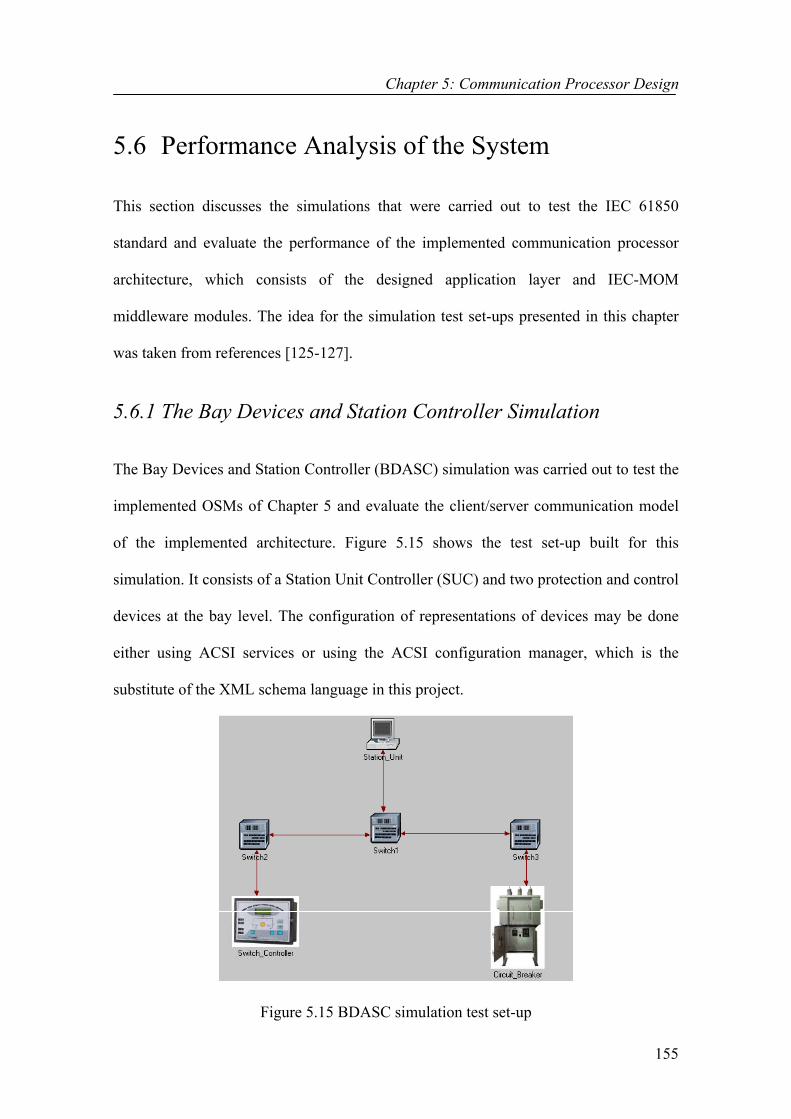
5.6.1 The Bay Devices and Station Controller Simulation The Bay Devices and Station Controller (BDASC) simulation was carried out to test the
implemented OSMs of Chapter 5 and evaluate the client/server communication model
of the implemented architecture. Figure 5.15 shows the test set-up built for this
simulation. It consists of a Station Unit Controller (SUC) and two protection and control
devices at the bay level. The configuration of representations of devices may be done
either using ACSI services or using the ACSI configuration manager, which is the
substitute of the XML schema language in this project.
Figure 5.15 BDASC simulation test set-up

Chapter 5: Communication Processor Design
156
One of the devices at the bay level was configured as an ACSI server representing the
functionality of a circuit breaker (XCBR). It contained a single LD, the LD1, and was
configured as a composition of the LNs: LLNO, LPHD and XCBR. Figure 5.16 depicts
the nested structure of this ACSI server only showing the components relevant to this
simulation. This simulation also intended to test and evaluate the reporting and logging
models of the IEC 61850 standard. Therefore, a DataSet and a BRCB were also
configured for the Circuit_Breaker making use of the ACSI services “CreateDataSet”
and “SetBRCBValues”.
ACSI Server
LD1
LLNO LPHD XCBR
stValctVal
ModePos
LN Instances
Compatible Data Class (CDC)
DataAttributes
Figure 5.16 Nested structure of the Circuit_Breaker
The DataSet and BRCB of the Circuit_Breaker were configured as follows:
DataSet:
DSName: DataSet1
DSRef: LD1/LLNO.DataSet1
DSMemberRef [0]: LD1/XCBR.Pos.ctVal [st]
DSMemberRef [1]: LD1/XCBR.Pos.stVal [sv]
BRCB:
BRCBName: BRCB1

Chapter 5: Communication Processor Design
157
BRCBRef: LD1/LLNO.BRCB1
RptID: BRCB1 Report Identifier
RptEna: TRUE
DatSet: LD1/LLNO.DataSet1
BufTm: 0
PurgeBuf: FALSE
TrgOp: data-change = TRUE
IntgPd: 0
OptFlds: sequence-number = TRUE, report-time-stamp = TRUE, reason-for-inclusion =
TRUE, data-set-name = TRUE, data-reference =TRUE, buffer-overflow =TRUE,
entryID = TRUE, conf-revision = TRUE
The second device at the bay level was configured as an ACSI server that represented
the virtual behaviour of a switch controller (CSWI). The Switch_Controller also
contained a single LD, the LD1, which was a composition of the LNs: LLNO, LPHD
and CSWI. Figure 5.17 shows the nested structure of the Switch_Controller illustrating
only the components with relevance to this simulation.
ACSI Server
LD1
LLNO LPHD CSWI
ctlNum
Pos
LN Instances
Compatible Data Class (CDC)
DataAttributes
Figure 5.17 Nested structure of the Switch_Controller
The Switch_Controller was moreover configured with a DataSet and a LCB to enable
the testing of the logging model. Unlike the Circuit_Breaker, all configuration of the

Chapter 5: Communication Processor Design
158
Switch_Controller was carried out using the offline method that’s by making use of the
ACSI Configuration Manager. The DataSet and LCB were configured as follows:
DataSet:
DSName: DataSet1
DSRef: LD1/LLNO.DataSet1
DSMemberRef [0]: LD1/CSWI.Pos.ctlNum [op]
LCB:
LCBName: lcb
LCBRef: LD1/LLNO.lcb
LogRef: LD1/LD1
LogEna: TRUE
DatSet: LD1/LLNO.DataSet1
IntgPd: 0
TrgOp: data-change = TRUE
OptFlds: reason-for-inclusion = TRUE
The following code segment shows the ACSI service requests that were issued to the
devices by the Station Unit Controller (SUC).
// Issue a “GetServerDirectory” ACSI request GetServerDirectory ("LOGICAL_DEVICE"); strcpy (Addr1->server, "Circuit_Breaker"); // Destination = Circuit Breaker PD // Issue a “GetLogicalDeviceDirectory” ACSI request GetLogicalDeviceDirectory ("LD1"); strcpy (Addr1->server, "Circuit_Breaker"); // Destination = Circuit Breaker PD // Issue a “GetLogicalNodeDirectory” ACSI request GetLogicalNodeDirectory ("LD1/XCBR", "DATA"); strcpy (Addr1->server, "Circuit_Breaker"); // Destination = Circuit Breaker PD // Issue a “CreateDataSet” ACSI request char** reff = new char*[2]; // Declare a variable for the DSMemberRef [1..2]

Chapter 5: Communication Processor Design
159
reff [0] = "LD1/XCBR.Pos.ctVal[st]"; // Set the value of DSMemberRef [0] reff [1] = "LD1/XCBR.Mode.stVal[sv]"; // Set the value of DSMemberRef [1] CreateDataSet ("LD1/LLNO.DataSet1", reff); // Issue the request strcpy (Addr1->server, "Circuit_Breaker"); // Destination = Circuit Breaker PD // Declare and initialise variables for the BRCB creation enum FC FunctionalConstraint = br; char ReportIdentifier[65] = "BRCB1 Report Identifier"; bool ReportEnable = true; char DataSetReference[255] = "LD1/LLNO.DataSet1"; PACKET_LIST_BOOLEAN OptionalFields; unsigned _int32 BufferTime = 0; TriggerConditions TriggerConditionsEnabled; unsigned _int32 IntegrityPeriod = 0; bool GeneralInterrogation =false; bool PurgeBuffer=false; binary_number* EntryIdentifier; TriggerConditionsEnabled.data_change = true; OptionalFields.packet_list_name = "OptFlds"; OptionalFields.list_members [0] = true; OptionalFields.list_members [1] = true; OptionalFields.list_members [2] = true; OptionalFields.list_members [3] = true; OptionalFields.list_members [4] = true; OptionalFields.list_members [5] = true; OptionalFields.list_members [6] = true; OptionalFields.list_members [7] = true; // Using the set variables, create a BRCB for the Circuit Breaker PD SetBRCBValues ("LD1/LLNO.BRCB1", FunctionalConstraint, ReportIdentifier, ReportEnable, DataSetReference, OptionalFields, BufferTime, TriggerConditionsEnabled, IntegrityPeriod, GeneralInterrogation, PurgeBuffer, EntryIdentifier); strcpy (Addr1->server , "Circuit_Breaker"); // Destination = Circuit Breaker PD // Write the values of the DataAttributes referenced by the DataSet1 void**Val = new void*[2]; Val[0] = (int*)true; Val[1] = (int*)12; SetDataSetValues ("LD1/LLNO.DataSet1", Val); strcpy (Addr1->server, "Circuit_Breaker"); // Destination = Circuit Breaker PD // Issue a “GetDataSetDirectory” ACSI request GetDataSetDirectory ("LD1/LLNO.DataSet1"); strcpy(Addr1->server , "Switch_Controller"); // Destination = Switch Controller PD // Issue a “GetDataValues” ACSI request GetDataValues ("LD1/CSWI.Pos.ctlNum[op]"); strcpy (Addr1->server, "Switch_Controller"); // Destination = Switch Controller PD
Chapter 5: Communication Processor Design
160
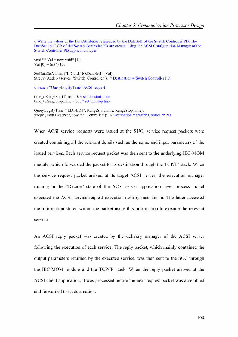
// Write the values of the DataAttributes referenced by the DataSet1 of the Switch Controller PD. The DataSet and LCB of the Switch Controller PD are created using the ACSI Configuration Manager of the Switch Controller PD application layer void ** Val = new void* [1]; Val [0] = (int*) 10; SetDataSetValues ("LD1/LLNO.DataSet1", Val); Strcpy (Addr1->server, "Switch_Controller"); // Destination = Switch Controller PD // Issue a “QueryLogByTime” ACSI request time_t RangeStartTime = 0; // set the start time time_t RangeStopTime = 60; // set the stop time QueryLogByTime ("LD1/LD1", RangeStartTime, RangeStopTime); strcpy (Addr1->server, "Switch_Controller"); // Destination = Switch Controller PD When ACSI service requests were issued at the SUC, service request packets were
created containing all the relevant details such as the name and input parameters of the
issued services. Each service request packet was then sent to the underlying IEC-MOM
module, which forwarded the packet to its destination through the TCP/IP stack. When
the service request packet arrived at its target ACSI server, the execution manager
running in the “Decide” state of the ACSI server application layer process model
executed the ACSI service request execution-destroy mechanism. The latter accessed
the information stored within the packet using this information to execute the relevant
service.
An ACSI reply packet was created by the delivery manager of the ACSI server
following the execution of each service. The reply packet, which mainly contained the
output parameters returned by the executed service, was then sent to the SUC through
the IEC-MOM module and the TCP/IP stack. When the reply packet arrived at the
ACSI client application, it was processed before the next request packet was assembled
and forwarded to its destination.

Chapter 5: Communication Processor Design
161
Figure 5.18 shows the event-by-event simulation summary that was received on the
simulation console. As shown in Figure 5.18, messages were displayed on the
simulation console when ACSI requests arrived and got executed at the ACSI servers
and when ACSI replies arrived and got executed at the SUC. Some of the output
parameters returned in the ASCI reply packets were also displayed.
Figure 5.18 BDASC simulation console output

Chapter 5: Communication Processor Design
162
It is also important to observe the “A report has been received in the Station_Unit”
message displayed on the simulation console. It indicates the report message that was
received at the Station Unit Controller (SUC) from the Circuit_Breaker. As to be
remembered, the Circuit_Breaker was enabled for reporting since a BRCB was
configured for that device. The configured BRCB continuously monitored the values of
the member DataAttributes of the specified DataSet and issued an immediate
transmission of the new values as soon as the old values changed as a result of the
SUC’s “SetDataSetValues” request. In contrast, the Switch_Controller was enabled for
logging as a LCB was configured for that device. The configured LCB continuously
monitored the values of the member DataAttributes of the specified DataSet and added
a new log entry into the log as soon as the old values changed as a result of the SUC’s
“SetDataSetValues” service request. This is indicated by the “A new log has been
added” message displayed on the simulation console. The new log entry was then
retrieved from the log by the SUC making use of the “QueryLogByTime” service.
Figure 5.19 shows the amount of data received at the SUC, which includes the ACSI
reply packets received from both ACSI servers as well as the report received from the
Circuit_Breaker. The size of the ACSI reply packets was measured as 288 bits and the
size of the report packet was measured as 224 bits. Figure 5.19 also shows the amount
of data received at the Circuit_Breaker, which includes the ACSI requests received from
the SUC. The size of the ACSI request packets was measured as 320 bits.
The speed of the links used, the choice of a transport protocol, message sizes, the
distance between the communicating nodes and message processing times in the
communication processor stack are amongst the factors that affect the application-to-

Chapter 5: Communication Processor Design
163
application (end-to-end) delay times. Figure 5.20 shows the application-to-application
delay times of various packets received at the SUC and Circuit Breaker when 100 Mbps
Ethernet drop links were used. Although the OPNET software does not allow the
distances between the communicating nodes to be measured, substantial distances were
allowed between the communicating nodes in the simulation test set-up with the aid of a
map based simulation background. No particular delay requirements do exist in the IEC
61850 standard for the transmission of non-time critical data such as ACSI request,
ACSI replies or reports. However, reasonable delay times, all of which less than 1ms,
were recorded in this simulation as illustrated in Figure 5.20 justifying the adequacy of
the designed communication architecture. It should also be bear in mind that TCP was
the transport protocol used for the transmission of these non-time critical data.
Figure 5.19 Amount of traffic (bits/sec) received at the
SUC and Circuit_Breaker

Chapter 5: Communication Processor Design
164
Figure 5.20 Application-to-application delays of packets received at the SUC and Circuit_Breaker
To get more insight into where the time was spent during the transmission of a 40 byte
ACSI request from the SUC to the Circuit_Breaker, the delay timing breakdown of such
a packet is provided in Table 5.1.
Table 5.1 Delay timing breakdown of a 40 byte request packet
Component Time (µs) IEC-MOM overhead 162 IP processing delay of SUC 20 On the wire delay 315 IP processing delay of Circuit_Breaker 4 Total 501
As illustrated in Table 5.1, the application-to-application delay has been broken up into
four major parts. IEC-MOM overhead is the time spent in the implemented middleware
architecture. IP processing delay refers to the delay experienced by an IP datagram

Chapter 5: Communication Processor Design
165
through the IP layer. “On the wire” delay is the delay the packet encounters on the
transmission link. Other protocol layer delays were observed to be insignificant (≈ 0).
It is to be noticed from Table 5.1 that the IEC-MOM overhead was relatively high. This
is solely due to the fact that the packet experienced a waiting delay in the middleware
queue module until the TCP connection was established with the destination host. As to
be remembered, TCP is a connection-oriented transport layer protocol that requires
establishing an application session with the destination node. As soon as the session was
established, the TPAL layer gave an “OPEN” confirmation to IEC-MOM after which
the packet was dispatched. However, as illustrated in Table 5.1, the packet did
experience a considerable waiting delay in the IEC-MOM middleware until the session
was established. Therefore, this large overhead is not directly related to the IEC-MOM
architecture but entirely to the TCP transport layer protocol.
5.6.2 The GOOSE Demo Simulation
The GOOSE Demo simulation was carried out to test the transfer of digital data
between bay devices according to the concepts outlined by the IEC 61850 standard
[128]. The objectives were to:
1. Demonstrate how virtual representations of real protection and control devices
can be developed in the simulation environment,
2. Verify the implemented GOOSE model (classes/services), and
3. Demonstrate the effectiveness of the designed communication architecture,
mainly the publish/subscribe communication model, in the handling and
distribution of time critical GOOSE messages.
Chapter 5: Communication Processor Design
166
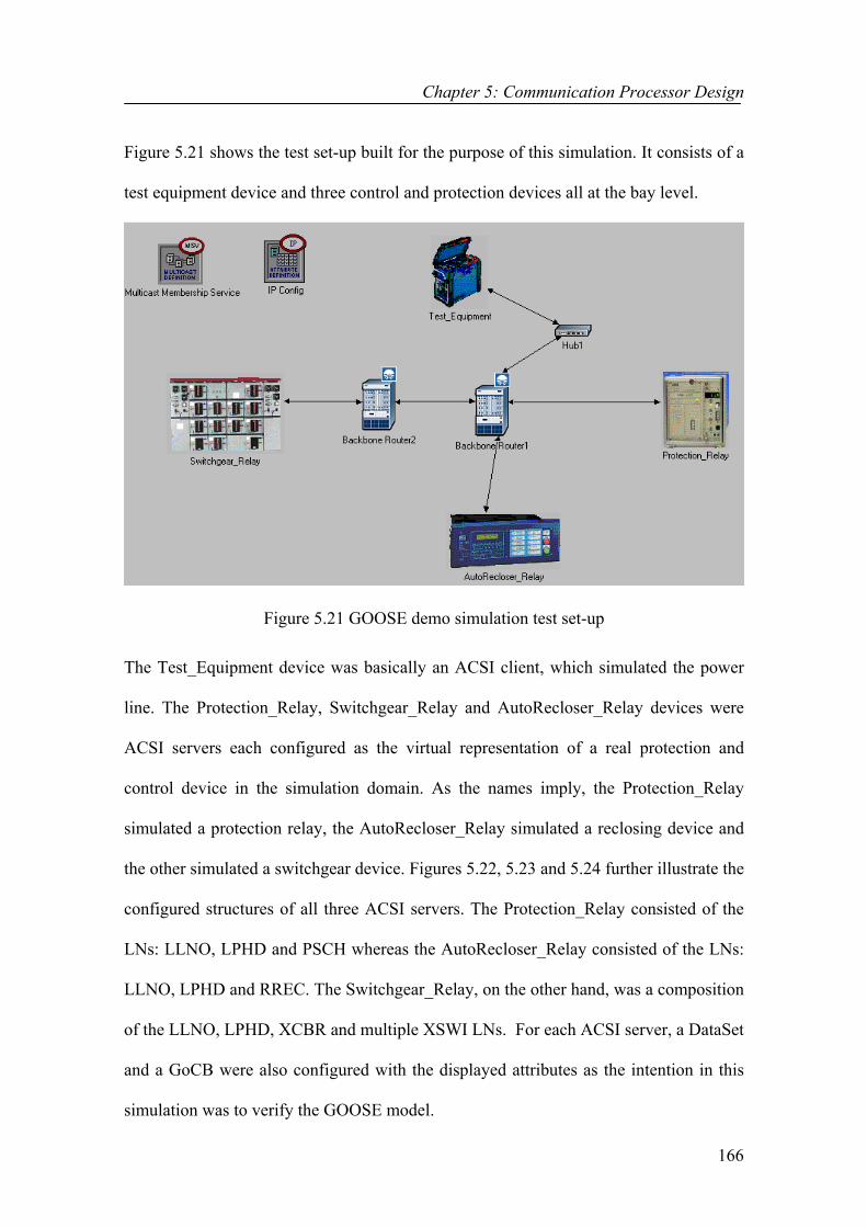
Figure 5.21 shows the test set-up built for the purpose of this simulation. It consists of a
test equipment device and three control and protection devices all at the bay level.
Figure 5.21 GOOSE demo simulation test set-up
The Test_Equipment device was basically an ACSI client, which simulated the power
line. The Protection_Relay, Switchgear_Relay and AutoRecloser_Relay devices were
ACSI servers each configured as the virtual representation of a real protection and
control device in the simulation domain. As the names imply, the Protection_Relay
simulated a protection relay, the AutoRecloser_Relay simulated a reclosing device and
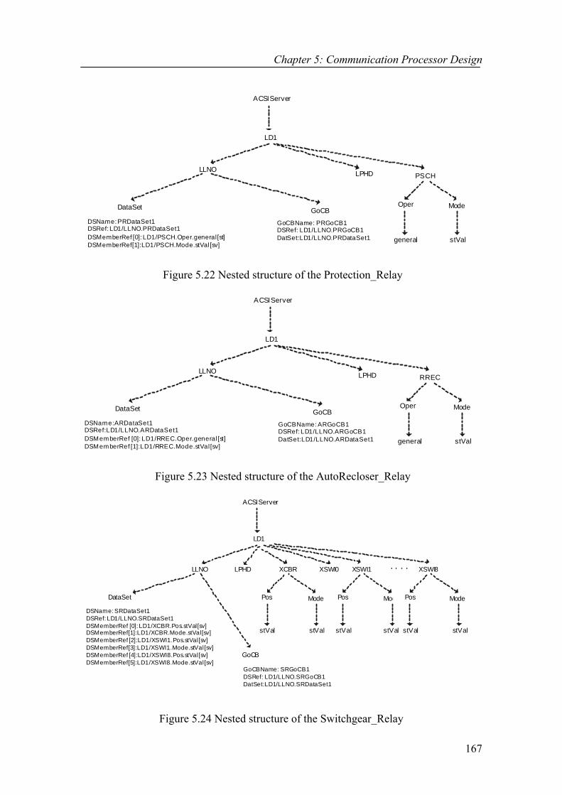
the other simulated a switchgear device. Figures 5.22, 5.23 and 5.24 further illustrate the
configured structures of all three ACSI servers. The Protection_Relay consisted of the
LNs: LLNO, LPHD and PSCH whereas the AutoRecloser_Relay consisted of the LNs:
LLNO, LPHD and RREC. The Switchgear_Relay, on the other hand, was a composition
of the LLNO, LPHD, XCBR and multiple XSWI LNs. For each ACSI server, a DataSet
and a GoCB were also configured with the displayed attributes as the intention in this
simulation was to verify the GOOSE model.
Chapter 5: Communication Processor Design
167
ACSI Server
LD1
LLNO LPHD PSCH
Oper Mode
general stVal
DataSet GoCBDSName: PRDataSet1DSRef: LD1/LLNO.PRDataSet1DSMemberRef [0]: LD1/PSCH.Oper.general[st]DSMemberRef [1]: LD1/PSCH.Mode.stVal[sv]
GoCBName: PRGoCB1DSRef: LD1/LLNO.PRGoCB1DatSet: LD1/LLNO.PRDataSet1
Figure 5.22 Nested structure of the Protection_Relay
ACSI Server
LD1
LLNO LPHD RREC
Oper Mode
general stVal
DataSet GoCBDSName: ARDataSet1DSRef: LD1/LLNO.ARDataSet1DSMemberRef [0]: LD1/RREC.Oper.general [st]DSMemberRef [1]: LD1/RREC.Mode.stVal[sv]
GoCBName: ARGoCB1DSRef: LD1/LLNO.ARGoCB1DatSet: LD1/LLNO.ARDataSet1
Figure 5.23 Nested structure of the AutoRecloser_Relay
ACSI Server
LD1
LLNO LPHD
DataSet
GoCB
DSName: SRDataSet1DSRef: LD1/LLNO.SRDataSet1DSMemberRef [0]: LD1/XCBR.Pos.stVal[sv]DSMemberRef [1]: LD1/XCBR.Mode.stVal[sv]DSMemberRef [2]: LD1/XSWI1.Pos.stVal[sv]DSMemberRef [3]: LD1/XSWI1.Mode.stVal[sv]DSMemberRef [4]: LD1/XSWI8.Pos.stVal[sv]DSMemberRef [5]: LD1/XSWI8.Mode.stVal[sv]
GoCBName: SRGoCB1DSRef: LD1/LLNO.SRGoCB1DatSet: LD1/LLNO.SRDataSet1
XCBR
Pos Mode
stVal stVal
XSWI0 XSWI1
Pos Mode
stVal stVal
. . . . XSWI8
Pos Mode
stVal stVal
Figure 5.24 Nested structure of the Switchgear_Relay

Chapter 5: Communication Processor Design
168
The Test_Equipment simulated a short circuit and fed the corresponding current into the
Protection_Relay. On receiving a fault current, the Protection_Relay issued a trip signal
to the Switchgear_Relay indicating that the relay had picked up. When the
Switchgear_Relay received the GOOSE message from the Protection_Relay, it opened
the circuit breaker in response to the GOOSE message. It then sent a GOOSE message,
which contained the status of the circuit breaker and switches, to all other devices.
When the AutoRecloser_Relay received the status (position) of the circuit breaker and
switches, it issued a “re-close” signal to the Switchgear_Relay. The Switchgear_Relay
re-closed the circuit breaker before sending the new status of the circuit breaker and
switches back to all other devices. The event-by-event simulation summary received on
the simulation console is shown in Figure 5.25. Text messages were displayed on the
simulation console as shown in Figure 5.25 for GOOSE subscription and notification
packets as well as GOOSE messages. Each time a new GOOSE message arrived at a
device, the publisher details of that GOOSE message were displayed together with the
response the receiving device took in reply to the GOOSE message.
Figure 5.25 GOOSE Demo simulation console output

Chapter 5: Communication Processor Design
169
GOOSE messages
Figure 5.26 shows the amount of data received at the Switchgear_Relay, which includes
the GOOSE subscription and notification packets as well as the GOOSE messages. The
size of the GOOSE subscription and notification packets was measured as 74 bits
whereas the size of the GOOSE messages was measured as 224 bits.
Figure 5.26 Amount of traffic received at the Switchgear_Relay
As illustrated in Figure 5.26, the Switchgear_Relay received a total number of eight
GOOSE messages shortly after the 5th minute. However, only two of these messages
were the event-driven GOOSE messages. The remaining six were the retransmissions of
the original event-driven GOOSE messages. Hence, three retransmissions took place for
every original event-driven GOOSE message. This was achieved by setting the setting
number (n) of equation (5.1) to four. The delays expected in between the first event-
driven message and the successive retransmissions were calculated as follows:

Chapter 5: Communication Processor Design
170
mst
mst
mst
7.10001.0)41(
5.00001.0)41(
2.00001.0)41(
133
122
111
=×+=
=×+=
=×+=
−
−
−
Figure 5.27 shows the application-to-application delay statistic of the GOOSE messages
received at the Switchgear_Relay. The measured delays include the transmission delay
as well as the delays through the protocol stack. For the retransmitted GOOSE
messages, they also include the retransmission waiting times.
Figure 5.27 Application-to-application delays of GOOSE messages received at the Switchgear_Relay
It can clearly be identified from Figure 5.27 that all measured delays satisfied the 4 ms
maximum delay requirement. Thus, the necessary trade off between the delivery delay
and reliability of GOOSE messages was achieved by repeating the first event-driven
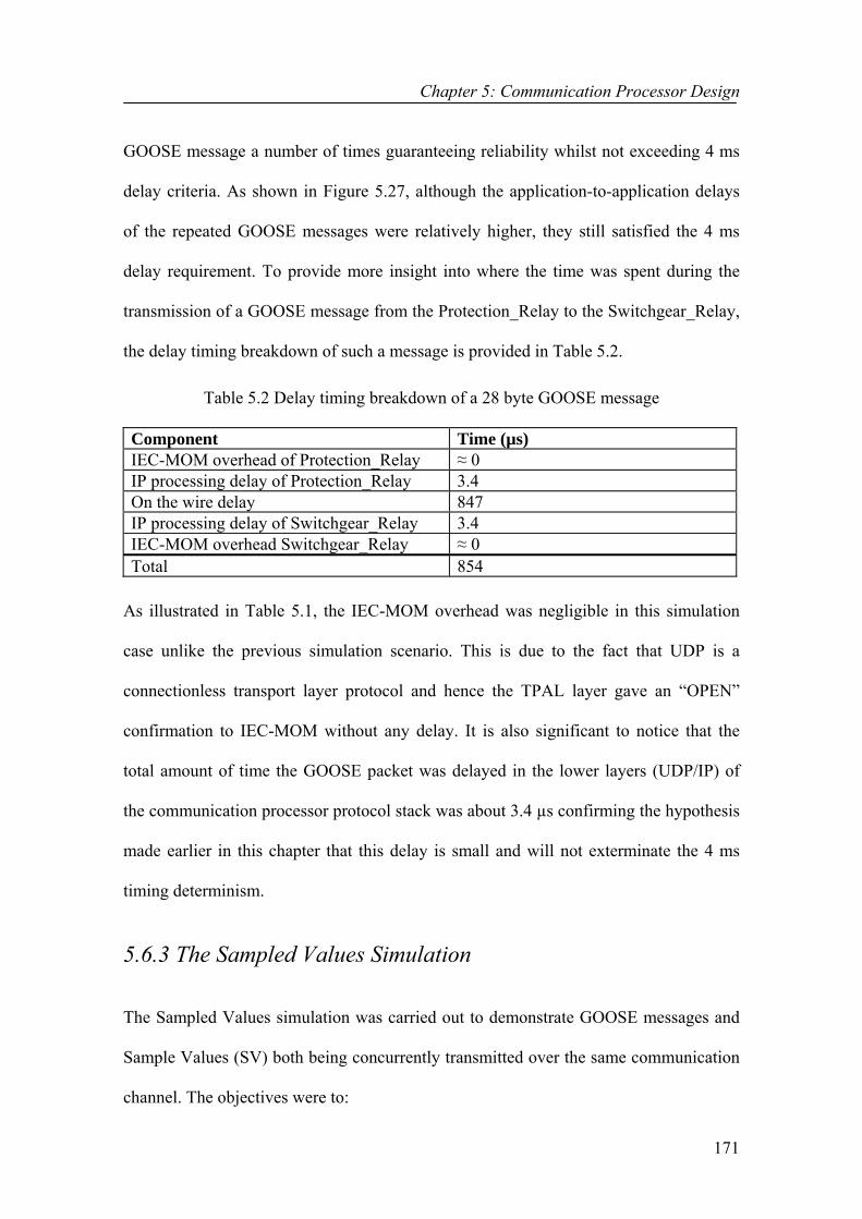
Chapter 5: Communication Processor Design
171
GOOSE message a number of times guaranteeing reliability whilst not exceeding 4 ms
delay criteria. As shown in Figure 5.27, although the application-to-application delays
of the repeated GOOSE messages were relatively higher, they still satisfied the 4 ms
delay requirement. To provide more insight into where the time was spent during the
transmission of a GOOSE message from the Protection_Relay to the Switchgear_Relay,
the delay timing breakdown of such a message is provided in Table 5.2.
Table 5.2 Delay timing breakdown of a 28 byte GOOSE message
Component Time (µs) IEC-MOM overhead of Protection_Relay ≈ 0 IP processing delay of Protection_Relay 3.4 On the wire delay 847 IP processing delay of Switchgear_Relay 3.4 IEC-MOM overhead Switchgear_Relay ≈ 0 Total 854
As illustrated in Table 5.1, the IEC-MOM overhead was negligible in this simulation
case unlike the previous simulation scenario. This is due to the fact that UDP is a
connectionless transport layer protocol and hence the TPAL layer gave an “OPEN”
confirmation to IEC-MOM without any delay. It is also significant to notice that the
total amount of time the GOOSE packet was delayed in the lower layers (UDP/IP) of
the communication processor protocol stack was about 3.4 µs confirming the hypothesis
made earlier in this chapter that this delay is small and will not exterminate the 4 ms
timing determinism.
5.6.3 The Sampled Values Simulation
The Sampled Values simulation was carried out to demonstrate GOOSE messages and
Sample Values (SV) both being concurrently transmitted over the same communication
channel. The objectives were to:

Chapter 5: Communication Processor Design
172
1. Verify the implemented SV model (classes/services), and
2. Demonstrate the effectiveness of the designed communication architecture in
the handling and distribution of time critical GOOSE messages and SV
simultaneously.
Figure 5.28 shows the test set-up built for the purpose of this simulation. The simulated
protection and control scenario was precisely same as the “GOOSE Demo” case except
that a new device, the Sensor_Simulation, was configured at the bay level. The
Sensor_Simulation continuously converted the analogue signals it received from the
Test_Equipment into SV and multicast them onto the bus. The Protection_Relay was
registered and subscribed to the Sensor_Simulation’s multicast group; therefore it
continuously received the SV packets sent by the Sensor_Simulation.
Figure 5.28 Sampled Values simulation test set-up
The Protection_Relay detected the short circuit after the 5th SV packet as illustrated in
Figure 5.29 and issued a trip signal to the Switchgear_Relay indicating that the relay
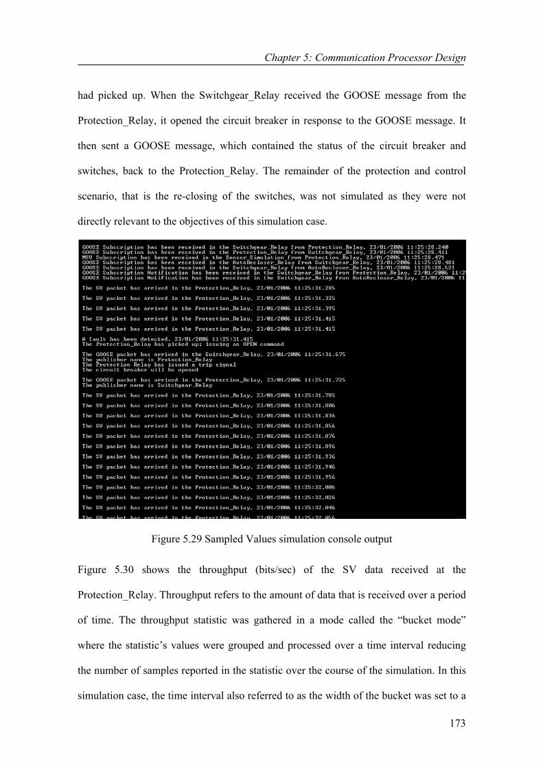
Chapter 5: Communication Processor Design
173
had picked up. When the Switchgear_Relay received the GOOSE message from the
Protection_Relay, it opened the circuit breaker in response to the GOOSE message. It
then sent a GOOSE message, which contained the status of the circuit breaker and
switches, back to the Protection_Relay. The remainder of the protection and control
scenario, that is the re-closing of the switches, was not simulated as they were not
directly relevant to the objectives of this simulation case.
Figure 5.29 Sampled Values simulation console output
Figure 5.30 shows the throughput (bits/sec) of the SV data received at the
Protection_Relay. Throughput refers to the amount of data that is received over a period
of time. The throughput statistic was gathered in a mode called the “bucket mode”
where the statistic’s values were grouped and processed over a time interval reducing
the number of samples reported in the statistic over the course of the simulation. In this
simulation case, the time interval also referred to as the width of the bucket was set to a

Chapter 5: Communication Processor Design
174
minute. The size of each individual SV packet was measured as 1200 bytes and the
Protection_Relay received a SV packet every second. The Protection_Relay drop link
utilized in this simulation case was 10 BASE-T. Therefore, an appropriate amount of
the Protection_Relay’s drop link was filled with the SV packets. Figure 5.30 also shows
the amount of GOOSE data received at the Protection_Relay as a result of the opening
of the circuit breaker in the Switchgear_Relay. The “GOOSE traffic” statistic was
gathered in the “All Values” mode where measurements of every individual transaction
are displayed instead of the time-oriented processing performed in the bucket-oriented
collection mode. A total number of four GOOSE messages including the first event-
driven GOOSE message and the three retransmissions were received in the
Protection_Relay. The size of the GOOSE messages was recorded as 224 bits.
Figure 5.30 SV traffic throughput (bits/sec) and the amount of GOOSE traffic received at the Protection_Relay

Chapter 5: Communication Processor Design
175
Finally, Figure 5.31 shows the application-to-application (end-to-end) delay statistic of
the GOOSE and SV packets received at the Protection_Relay. As illustrated in Figure
5.31, the application-to-application delay times of the SV packets are steady at 0.85 ms
as well as the end-to-end delay of the first event-driven GOOSE message. As expected,
an increase in the application-to-application delays of the repeated GOOSE messages
was observed that is primarily due to the waiting times in between the retransmissions.
However, as shown in Figure 5.31, all measured delays still satisfied the 4 ms maximum
delay criteria. Thus, the simulations carried out in this simulation case have verified the
implemented SV model and demonstrated that the 4 ms maximum delay requirement
can still be met in the case of GOOSE and SV messages both being simultaneously
transmitted over the same communication channel.
Figure 5.31 Application-to-application delays of GOOSE and SV messages received at the Protection_Relay

Chapter 5: Communication Processor Design
176
Even in cases where the network is much more heavily loaded with the SV data, it will
still be possible to meet the 4 ms delay requirement imposed for the transmission of
GOOSE messages. This is due to the fact that GOOSE messages have been given the
highest priority at every step along the network as a result of the mechanisms employed
in the designed IEC-MOM middleware and through the use of the RSVP protocol. This
ensures that the delivery of GOOSE messages takes place taking the order of traffic into
consideration at every step along the network. Thus, even if an outgoing router port is
busy with transferring larger or more frequent SV data, as soon as a GOOSE message is
received, it will be processed first and forwarded to its destination. Hence, in such
extreme cases, the timing determinism of SV data can be traded off in order to achieve
the timing determinism of more important GOOSE data. After taking all these
measures, the fulfilment of the QoS requirements will merely depend on issues such the
forwarding and processing capacity of the routers and other devices on the network.
5.7 Conclusion This chapter has presented a communication processor architecture that enables the
configuration of ACSI client and server applications as well as maintaining support for
all the communication models and techniques required for the reliable, fast and efficient
transmission of IEC 61850 related application data. The designed architecture consists
of application layer modules built on top of a middleware architecture running on
protocol stack that incorporates the TCP/UDP-IP network protocols. The ACSI client
and server applications can be configured at the application layer modules making use
of the C++ class and service descriptions of Chapters 3 and 4. The designed application
layers fully collaborate with and assist the underlying IEC-MOM middleware with
Chapter 5: Communication Processor Design
177
regards to time-critical multicast data transfer through a range of mechanisms such as
registering, subscription, binding and filtering.
The designed communication middleware does not include any object or service
models. It only integrates various message distribution mechanisms for the transmission
of messages received from the ACSI application layers. It is small, fast and efficient.
The IEC-MOM middleware provides an identical programming model for unicast or
multicast and an identical programming model for sources and sinks thus achieving ease
of programming. Efficiency has been achieved by making sure that the real-time
communications make minimal expenditure of computer resources by using locally
stored information and duplication of messages going to multiple receivers.
The remainder of this chapter evaluated the performance of the communication model
with the help of simulations. The simulations showed that the designed middleware
architecture can be used effectively to provide the necessary communication services to
ACSI clients and servers adding only nominal overhead to the underlying protocol
stack. It was also demonstrated that timely and reliable transmission of GOOSE
messages can be achieved with the aid of a trade-off mechanism that retransmits
GOOSE messages a few times whilst not exterminating the 4 ms timing determinism.
Finally, a more realistic network loading case was examined where an appropriate
amount of the receiving device’s drop link was filled with SV data. The simulations
carried out in the latter case have verified the accurate workings of the GOOSE and SV
models of Chapter 4 and showed that the designed architecture is capable of meeting the
timing determinism and reliability concerns even in the case of GOOSE and SV
messages both being simultaneously transmitted over the same communication channel.

Chapter 6: Substation Time Synchronisation
178
Chapter 6 Substation Time Synchronisation
6.1 Introduction
This chapter presents the implementation of the Simple Network Time Protocol (SNTP)
and the incorporation of SNTP client applications into ACSI application layer modules
of Chapter 5. Time Synchronisation (TS) involves harmonising the local clocks of all
the nodes within a network relative to a chosen reference so that sensing and actuation
of time-sensitive data can be coordinated accurately across multiple nodes. The
importance of TS has also been recognised by the IEC 61850 standard, which specifies
the need for TS in substation applications and sets different levels of accuracy
requirements for various protection functions. The TS protocol chosen in this research is
SNTP, a simplified version of the Network Time Protocol (NTP), which is often
regarded as the most accurate and flexible way of clock synchronisation over Ethernet.
This chapter is structured as follows: Section 6.2 gives an overview of Network Time
Synchronisation (NTS) and its importance in substation applications. SNTP is discussed
in detail in Section 6.3 along with its implementation details. Section 6.4 presents how a
stand-alone SNTP server is implemented in a separate communication processor and
discusses how SNTP client applications can be incorporated into the ACSI application

Chapter 6: Substation Time Synchronisation
179
layer modules. Section 6.5 provides a number of simulation case studies carried out to
evaluate the TS design whilst conclusions of this chapter are presented in Section 6.6.
6.2 Network Time Synchronisation
NTS is a crucial element of network design and implementation. A time-synchronised
network is vital for the operation of network applications with optimal performance.
The ultimate goal of TS is to bring the local clocks of servers and other instrumentation
in a network into phase so that their time differences will be zero. A typical TS process,
shown in Figure 6.1, may be divided into the following steps:
Time ServerSwitchClient1
Client2
Time request from client to server
Time response from server to client
Figure 6.1 The basic TS process
(1) One of the nodes within the network is chosen as the Time Server (TimeServer)
signifying that all other nodes within the same network need to synchronise their
clocks with the TimeServer’s local clock,
(2) A Time Client (TimeClient) initiates a time request to the TimeServer receiving
the TimeServer’s local clock time within a reply packet,
(3) The TimeClient, then, computes the difference between its own time setting and
the time setting it receives from the TimeServer and uses this difference to
adjust its internal clock bringing it into phase with that of the TimeServer.
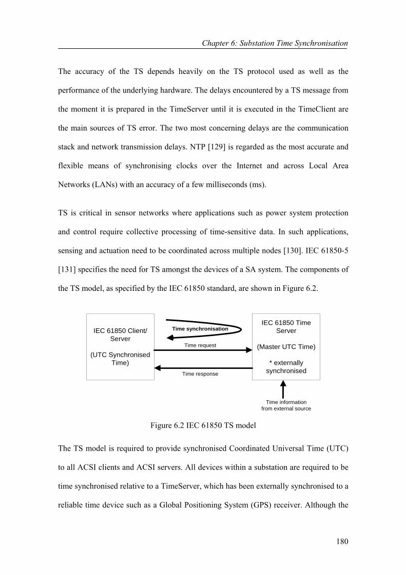
Chapter 6: Substation Time Synchronisation
180
The accuracy of the TS depends heavily on the TS protocol used as well as the
performance of the underlying hardware. The delays encountered by a TS message from
the moment it is prepared in the TimeServer until it is executed in the TimeClient are
the main sources of TS error. The two most concerning delays are the communication
stack and network transmission delays. NTP [129] is regarded as the most accurate and
flexible means of synchronising clocks over the Internet and across Local Area
Networks (LANs) with an accuracy of a few milliseconds (ms).
TS is critical in sensor networks where applications such as power system protection
and control require collective processing of time-sensitive data. In such applications,
sensing and actuation need to be coordinated across multiple nodes [130]. IEC 61850-5
[131] specifies the need for TS amongst the devices of a SA system. The components of
the TS model, as specified by the IEC 61850 standard, are shown in Figure 6.2.
IEC 61850 Client/Server
(UTC SynchronisedTime)
IEC 61850 TimeServer
(Master UTC Time)
* externallysynchronised
Time request
Time response
Time synchronisation
Time informationfrom external source
Figure 6.2 IEC 61850 TS model
The TS model is required to provide synchronised Coordinated Universal Time (UTC)
to all ACSI clients and ACSI servers. All devices within a substation are required to be
time synchronised relative to a TimeServer, which has been externally synchronised to a
reliable time device such as a Global Positioning System (GPS) receiver. Although the

Chapter 6: Substation Time Synchronisation
181
general features of a TS model are provided in IEC 61850, no specific descriptions of a
TS protocol are given. Instead, the Simple Network Time Protocol (SNTP) is hinted
out. Whether SNTP or another protocol is chosen, it must meet the requirements
specified in IEC 61850-5. According to IEC 61850-5, different levels of TS accuracy
requirements exist for diverse protection functions. Table 6.1 illustrates how the
different levels of TS accuracy requirements are set in IEC 61850-5 [131].
Table 6.1 IEC Classes T1-T5
IEC Class T1 ±1 ms
IEC Class T2 ± 0.1 ms
IEC Class T3 ± 25 µs
IEC Class T4 ± 4 µs
IEC Class T5 ± 1 µs
In this chapter, the focus is on describing how a fine grained TS function can be
incorporated into the designed communication architecture in order to synchronise
clocks of all devices within a substation network. The objective is to exemplify how the
SNTP TS protocol, with additionally included features, can be sufficient enough to meet
the accuracy requirements in substations by a means of time stamping at the lowest
possible stack layer instead of the application layer. In this phase of this project, the
synchronisation of substation nodes relative to a TimeServer has been looked into
excluding the process of externally synchronising the TimeServer’s local clock relative
to a real-time clock. A possible future inclusion to this part of this research would be the
modelling and implementation of a GPS device to take into account the process of
external synchronisation.
Chapter 6: Substation Time Synchronisation
182
6.3 Simple Network Time Protocol
Simple Network Time Protocol (SNTP) is a simplified version of NTP containing only
a subset of the NTP functionality [132]. The need for SNTP arose when a full
implementation of NTP seemed too complicated for many systems leading to the
development of SNTP. SNTP lacks some of the internal algorithms of NTP such as the
advanced filtering techniques used to control variable latency. However, it is still
considered to be adequate in meeting the TS demands of many systems within
acceptable accuracies.
SNTP is designed to produce two end products (variables): clock offset and roundtrip
delay. Another third product, dispersion that is normally not used in SNTP but in NTP,
is also utilised in this project. All of the above end products are calculated relative to a
selected clock reference (TimeServer). Clock offset is the amount of time to adjust the
local clock bringing it into agreement with the reference clock. In other words, it is the
time difference between the two. In addition to the time adjustment, the frequency
deviation (skew) of the local clock relative to the reference clock also needs to be
corrected. Skew can easily be calculated based on the clock offset. Roundtrip delay is
the two-way propagation delay between the TimeClient and TimeServer. Finally,
dispersion is the maximum local clock error relative to the reference clock [129].
6.3.1 SNTP Operation Modes SNTP can be implemented based on either client/server (unicast) or publish/subscribe
(multicast) modes of operation. In the client/server mode, a TimeClient sends a time
request to a designated TimeServer and waits for a reply by which it can determine the

Chapter 6: Substation Time Synchronisation
183
Round-Trip Delay (RTD), Local Clock Offset (LCO) and dispersion relative to the
TimeServer [132, 133]. SNTP uses the NTP message format shown in Figure 6.3.
Figure 6.3 SNTP message format
SNTP uses five different timestamps to represent the time values. Timestamps are 64-
bit unsigned integers representing time values in seconds relative to 0h on 1 January
1900. In addition to timestamps, the SNTP message format also consists of a number of
other fields such as Root Delay and Root Dispersion, which are not to be discussed in
detail in this chapter. More information on the latter can be obtained from [132]. The
descriptions of the timestamps used within the SNTP framework are given below [132]:
• Reference Timestamp: is the time at which the local clock is last set or corrected
in the TimeClient,
• Originate Timestamp (T1): is the time at which the time request leaves the
TimeClient headed to the TimeServer,
• Receive Timestamp (T2): is the time when the time request arrives at the
TimeServer,
• Transit Timestamp (T3): is the time at which the time reply leaves the
TimeServer headed to the TimeClient, and

Chapter 6: Substation Time Synchronisation
184
• Destination Timestamp (T4): is the time when the time reply arrives at the
TimeClient.
The sequence of events that take place in a unicast SNTP application is as follows:
a) The T3 field of the time request is set to the time of the day by the TimeClient
according to its own local clock,
b) When the time request arrives at the TimeServer, it copies the T3 field into the
T1 field and further sets T2 and T3 fields according to its own local clock
before forwarding the time reply back to the TimeClient,
c) When the time reply arrives at the TimeClient, it determines the time of its
arrival and sets this time into the T4 field,
d) The client application calculates the RTD (δ), LCO (θ) and dispersion (ε)
according to the following formulae [129]:
RTD = δ = T4-T1-T2+T3 equation (6.1)
LCO = θ = (T2-T1+T3-T4)/ 2 equation (6.2)
Dispersion = ε = ρ + ϕ(T4 − T1) equation (6.3)
Where T1, T2, T3, and T4 are the timestamp values, ρ is the measurement error, and
ϕ is the maximum skew rate given by the formula:
(6.4)equation .
EWSNTP.MAXSK MAXAGESNTP
=ϕ
Where MAXSKEW and MAXAGE are constants denoting the maximum skew error
and maximum clock age respectively. Skew is the frequency difference between the

Chapter 6: Substation Time Synchronisation
185
local and reference clocks. Clock age is the duration a reference clock is considered
valid [129]. The client application uses the value of the calculated LCO to advance its
local clock with t + LCO units during the next t time units bringing it into agreement
with that of the TimeServer. The client application can calculate the frequency (f´) it
needs to have using the formula: f´ = f / (1-LCO/T) where f is its current frequency and
T is the synchronisation period [134].
In a publish/subscribe SNTP application, the TimeServer uses a multicast group address
for periodically forwarding time updates. The key disadvantage concerned with the
publish/subscribe mode of operation is the fact that TimeClients can not calculate the
RTD based on equation (6.1) since the received multicast messages only have their T1
and T4 fields set. However, this disadvantage can easily be eliminated if each
TimeClient sends a single dummy unicast packet to the TimeServer at the start-up with
the intention of calculating the RTD. When the dummy unicast packet is received back
from the TimeServer, it will have all the timestamps making it possible to calculate the
RTD. Once the RTD is calculated, the TimeClient only listens and waits for the
multicast time updates. On their arrival, the client applications simply calculate the LCO
and make the necessary adjustments based on equation (6.5).
LO_multicast = (T1-T4) + (RTD/2) equation (6.5)
6.3.2 SNTP Implementation This section discusses the interface used, which provides the necessary Microsoft
Foundation Classes (MFCs) used to encapsulate SNTP. The interface is a collection of
freeware classes taken from the CSNTPClient project [135], which provides a total
Chapter 6: Substation Time Synchronisation
186
number of twelve Object Oriented (OO) structures and classes. Some of the classes are
aimed at implementing the core SNTP structure such as the timestamp structure while
others provide synchronous sockets and packet structures for workstation to workstation
communication. However, only the classes related to the core SNTP structure have been
utilised in this project. Their descriptions are provided below:
1) CNtpTimePacket Structure
The CNtpTimePacket structure is a representation of the SNTP timestamp format,
which consists of an integer and a fraction part each having a 32-bit unsigned fixed-
point number type. The C++ definition of the CNtpTimePacket structure, taken from
[135], can be viewed in Appendix C.
2) CNtpTime Class
The CNtpTime Class is an encapsulation of a time instance of the SNTP protocol
consisting of a 64-bit unsigned integer with the top 32 bits containing the number of
seconds elapsed since 1st January 1900 and the lower 32 bits containing the fraction of
seconds [135]. The C++ definition of the CNtpTime class is listed in Appendix C.
6.3.3 SNTP Filtering In this section, the use of adaptive filtering techniques to cope with the sources of errors
in TS schemes is explained. The major cause of error in a TS scheme, where Ethernet is
being used as the transfer media, is the non-deterministic structure of the Ethernet. This
non-determinism results in variable message delivery delays. The major sources of TS
error, all stemming from the non-deterministic property, are reviewed below [130, 136]:

Chapter 6: Substation Time Synchronisation
187
• Transmit protocol stack delay: is the delay a packet encounters when travelling
from the application layer, where it is assembled, all the way down to MAC
layer. Also referred to as “Send Time”, this delay is highly non-deterministic,
• Receive protocol stack delay: is the time it takes an incoming packet to travel
from MAC layer up till the application layer. Also referred to as “Receive
Time”, this delay is also highly variable, and
• Switch latency: is the time it takes a networking device such as a router to
process a data frame. Switch latency is highly dependent on the architecture of
the networking device and also the network load. The amount of time a packet is
delayed through a switch may vary differently based on the switch load.
Although SNTP does not actually incorporate any filtering mechanisms, the need for
such a mechanism to deal with the variable switch latency was clearly recognised in this
project. Hence, an important feature of NTP, the clock filter procedure was incorporated
into the SNTP implementation.
The NTP clock filter procedure uses the clock offset, roundtrip delay and dispersion
variables as its input arguments. It is executed each time a new NTP message arrives (in
this case SNTP) where a new set of data samples (θ, δ, ε) is calculated and shifted into
the filter at the left end. A shift register consisting of many shift stages is used for the
storing and shifting process. The whole idea of this procedure is to calculate the filtered
clock offset, roundtrip delay and dispersion values updating the dispersion of the
samples previously received and saving the current time. It is based on the computation
of a quantity called the synchronisation distance (λ) from the roundtrip delay and
dispersion making use of the following formulae [129]:

Chapter 6: Substation Time Synchronisation
188
(6.6)equation 2
|| δελ +=
All sets of samples contained within the filter are sorted by increasing synchronisation
distance and the set of values with the minimum synchronisation distance is chosen as
the end products that correspond to the filtered clock offset, roundtrip delay and
dispersion. Reference [129] contains an appendix illustrating C-language
implementations of all the various filtering and selection algorithms suggested for NTP.
The C-language code segment for the clock filter procedure is amongst these. Although
full code taken from [129] was utterly tested, it was observed that it ceased to function
in the desired manner until all the filter stages were filled. Although it successfully sorts
the list by increasing λ, it fails to pick the sample set corresponding to the minimum λ in
cases where not all the filter stages are filled. An additional code segment was therefore
added to the original code to solve this problem. Appendix C includes the pseudo-code
that describes the full procedure of the modified NTP clock filter algorithm.
6.4 Implementation of SNTP client and server applications
In this section, the implementation of SNTP client and server applications is discussed.
SNTP client applications can be integrated into the IEC 61860 related applications
running at the ACSI application layer modules of the communication processor as
shown in Figure 6.4. They share the same connectivity functionalities of the underlying
middleware with the IEC 61850 related applications for interacting across the network.
An ACSI server represents the external visible behaviour of a real device. With regards
to TS, it may also act as a SNTP TimeClient. In any network, there could be as many as

Chapter 6: Substation Time Synchronisation
189
SNTP clients. However, hypothetically a single SNTP server is allowed. In this
research, the SNTP server was designed and implemented in a separate communication
processor as a single-application running node as shown in Figure 6.5.
IEC 61850 Server application
SNTP Client application
Figure 6.4 ACSI server node Figure 6.5 SNTP TimeServer node
6.4.1 Application Layer Process Modelling of a SNTP Client
The State Transition Diagram (STD) of the entire application layer module of an ACSI
server is shown in Figure 6.6. The intact state diagram consists of six states, only two of
which are related to the SNTP application. They are the “Time_Syn” and “Decide”
states. The remaining states are all related to the IEC 61850 associated applications and
SNTP SERVER
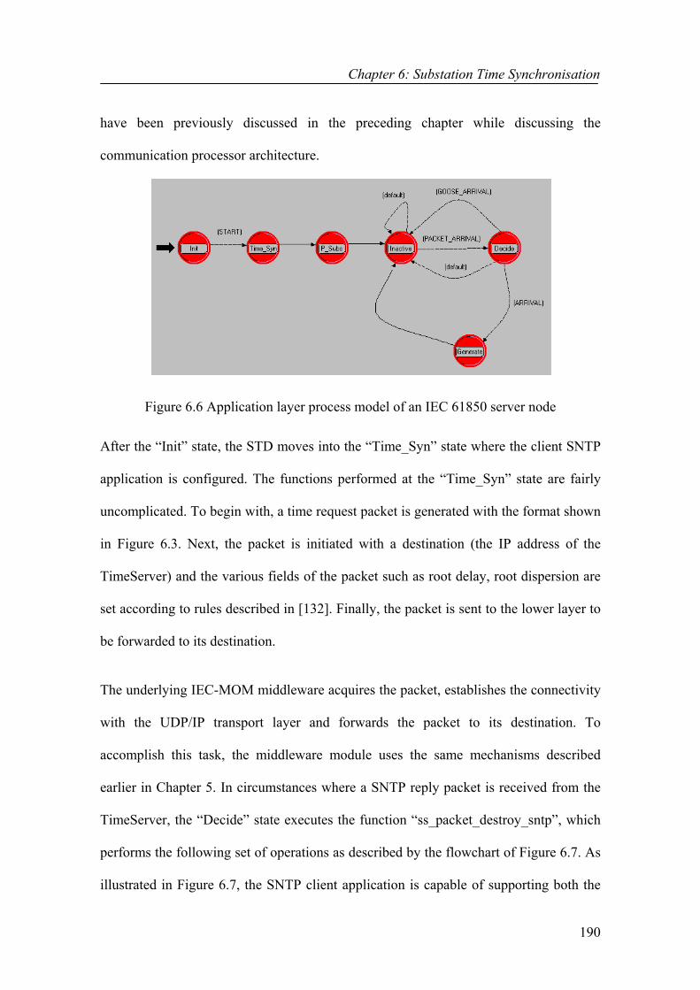
Chapter 6: Substation Time Synchronisation
190
have been previously discussed in the preceding chapter while discussing the
communication processor architecture.
Figure 6.6 Application layer process model of an IEC 61850 server node
After the “Init” state, the STD moves into the “Time_Syn” state where the client SNTP
application is configured. The functions performed at the “Time_Syn” state are fairly
uncomplicated. To begin with, a time request packet is generated with the format shown
in Figure 6.3. Next, the packet is initiated with a destination (the IP address of the
TimeServer) and the various fields of the packet such as root delay, root dispersion are
set according to rules described in [132]. Finally, the packet is sent to the lower layer to
be forwarded to its destination.
The underlying IEC-MOM middleware acquires the packet, establishes the connectivity
with the UDP/IP transport layer and forwards the packet to its destination. To
accomplish this task, the middleware module uses the same mechanisms described
earlier in Chapter 5. In circumstances where a SNTP reply packet is received from the
TimeServer, the “Decide” state executes the function “ss_packet_destroy_sntp”, which
performs the following set of operations as described by the flowchart of Figure 6.7. As
illustrated in Figure 6.7, the SNTP client application is capable of supporting both the

Chapter 6: Substation Time Synchronisation
191
unicast and multicast modes of operation. In both cases, the necessary timestamps are
acquired and the LCO and skew are calculated to be used in the process of correcting
the local clock relative to the chosen TimeServer.
No Yes
Compute the LCO and skew
START
Is packetfrom a
MulticastSNTP
Server?Obtain the
Transmit andReceive
Timestamp values
Obtain all fourtimestamp values
Compute the LCO,RTD and skew
Adjust the local clock using thevalues of the LCO and skew
End
Identify the sourceof the packet
Figure 6.7 Flowchart description of the ss_packet_destroy_sntp function
Ideally, T3 needs to be set at the application layer before the packet is sent. However,
studies undertaken by [133, 136] have shown that when time stamping is performed at
the application layer, the timing accuracy will heavily suffer from the latency and jitter
imposed by the UDP/IP transport layer. Such a timing accuracy might only satisfy the
IEC Class T1. Therefore, different techniques besides the technique of adaptive filtering
need to be used to be able to meet the harsh timing accuracy requirements imposed by

Chapter 6: Substation Time Synchronisation
192
the IEC 61850 standard. In [133, 136], the authors propose three techniques as a
solution:
1) Implementation of the TimeServer in the Ethernet switches,
2) Time stamping at the Ethernet data link/physical level, and
3) Time stamping at the Ethernet driver level.
These techniques originate from the fact that the location on the protocol stack, where
the time stamping of incoming and outgoing packets is performed, has an impact on the
amount of latency and jitter. Sub-section (6.4.3) discusses and compares the above
techniques detailing the approach chosen for implementation.
6.4.2 Application Layer Process Modelling of a SNTP Server
In contradiction to the SNTP client model, the SNTP server is fairly primitive since it is
designed as a single application running node. The STD diagram of the SNTP
TimeServer application layer is shown in Figure 6.8.
Figure 6.8 Application layer process model of an SNTP server node

Chapter 6: Substation Time Synchronisation
193
Similar to the SNTP client model, the SNTP server model is also designed to sustain
both of the operation modes. The most important function of the “init” state is to
schedule the frequency, start and end times of the multicast updates with the destination
address of the multicast packet set to the multicast address of “224.0.1.4”. Once the
multicast updates have been scheduled for transmission, STD enters into the
“Time_Syn” state where it stays until the end of the simulation. The “Time_Syn” state
waits for steam interrupts caused by the arrival of SNTP requests. On the arrival of a
SNTP request, the exit executive of the “Time_Syn” state performs the following set of
operations:
1. Obtains a pointer to a packet that has arrived on an input packet stream, and
removes the packet from the stream,
2. Obtains the source details of the received SNTP request,
3. Creates a new reply packet for the node that the request was received from,
4. Gets T3 from its field in the request packet and copies it into the T1 field of the
reply packet, and
5. Sends the reply packet to the lower layer to be forwarded to its destination.
6.4.3 Time Stamping This sub-section discusses the time stamping techniques before detailing the
implementation of the chosen approach. The need for such techniques has evolved from
the fact that when time stamping is carried out at the application layer, the relative time
accuracy could be in the range of a few milli seconds (ms) much higher than what is
needed by some applications, e.g. IEC class T5 requirement of 1µs.
Chapter 6: Substation Time Synchronisation
194
6.4.3.1 Implementation of the Time Server in the Ethernet Switches References [133, 136] discuss the implementation of TimeServers in Ethernet switches.
It is claimed that when a TimeServer is implemented in an Ethernet switch and time
stamping is performed at the lowest possible stack layer, it becomes possible to achieve
a timing accuracy of better than 1µs. This is promising since when the TimeServer is
implemented in the switch, the switch latency dilemma can be entirely eradicated. The
only drawback is that only one switch can be allowed between a TimeClient and a
TimeServer. Otherwise, TS suffers from increased jitter through the infrastructure.
This approach works perfectly well when all of the TimeClients can be interconnected
to a single TimeServer Ethernet switch. In cases where they are widespread and can not
all be connected to the same switch, the use of several TimeServers becomes necessary.
Nevertheless, the use of multiple TimeServers, all implemented in different Ethernet
switches in the same network, is highly undesirable. The latter inflicts the need for TS
between the TimeServer clocks themselves, which not only adds further load to the
network but also unlikely to provide high TS accuracies. The switch latency problem
will yet again turn out to be a critical issue when the distributed TimeServers try to
synchronise themselves. Although a solution to this problem has been given in reference
[133], it needs further investigation.
6.4.3.2 Time Stamping at the Ethernet Data Link/Physical Level This, as described by reference [133], involves time stamping in the hardware either in
the Ethernet controller or in a separate Field Programmable Gate Array (FPGA), which
completely removes the latency through the protocol stack. Reference [133] claims that
Chapter 6: Substation Time Synchronisation
195
this approach will provide an accuracy of better than 1µs provided that a single direct-
wire is used although no simulation results are provided to support this claim.
6.4.3.3 Time Stamping at the Ethernet Driver Level This requires time stamping of the T2 and T4 fields in the Ethernet “Receive” routine
and T1 and T3 fields in the Ethernet “Send” routine. Time Stamping at the Ethernet
driver level helps to remove a significant fraction of the stack latency and yields to
much higher TS accuracies. This was the approach chosen in this study primarily due to
its ease of implementation and high suitability. Although reference [133] states that T3
should not be time stamped in the Ethernet Send routine due to the fact that it is already
included in the reply packet coming from the application layer, it has to be disagreed
with that statement. When the application layer of a TimeServer receives a time request
packet, it generates a time reply packet and copies the T3 field of the request packet to
the T1 field of the reply packet. Consequently, the packet arriving at the Ethernet driver
of the TimeServer will have its T1, T2 and T3 fields set. Although set, the value stored
in the T3 field of the reply packet is no longer necessary (already copied to the T1 field)
and can absolutely be re-set it in the Ethernet driver of the TimeServer node.
The remainder of this sub-section discusses the changes made to the standard Media
Access Control (MAC) layer to allow time stamping in that protocol. Figure 6.9 shows
the STD diagram of MAC, which is one of the available modules in the OPNET’s
model library. Several alterations were made to the “ethernet_mac_phys_pk_accept ()”
and “eth_mac_fdx_pks_send ()” routines of the standard MAC layer module to enable
time stamping of the T1, T2, T3 and T4 fields at the Ethernet driver level. The pseudo-
code descriptions of both routines are provided in Appendix C.
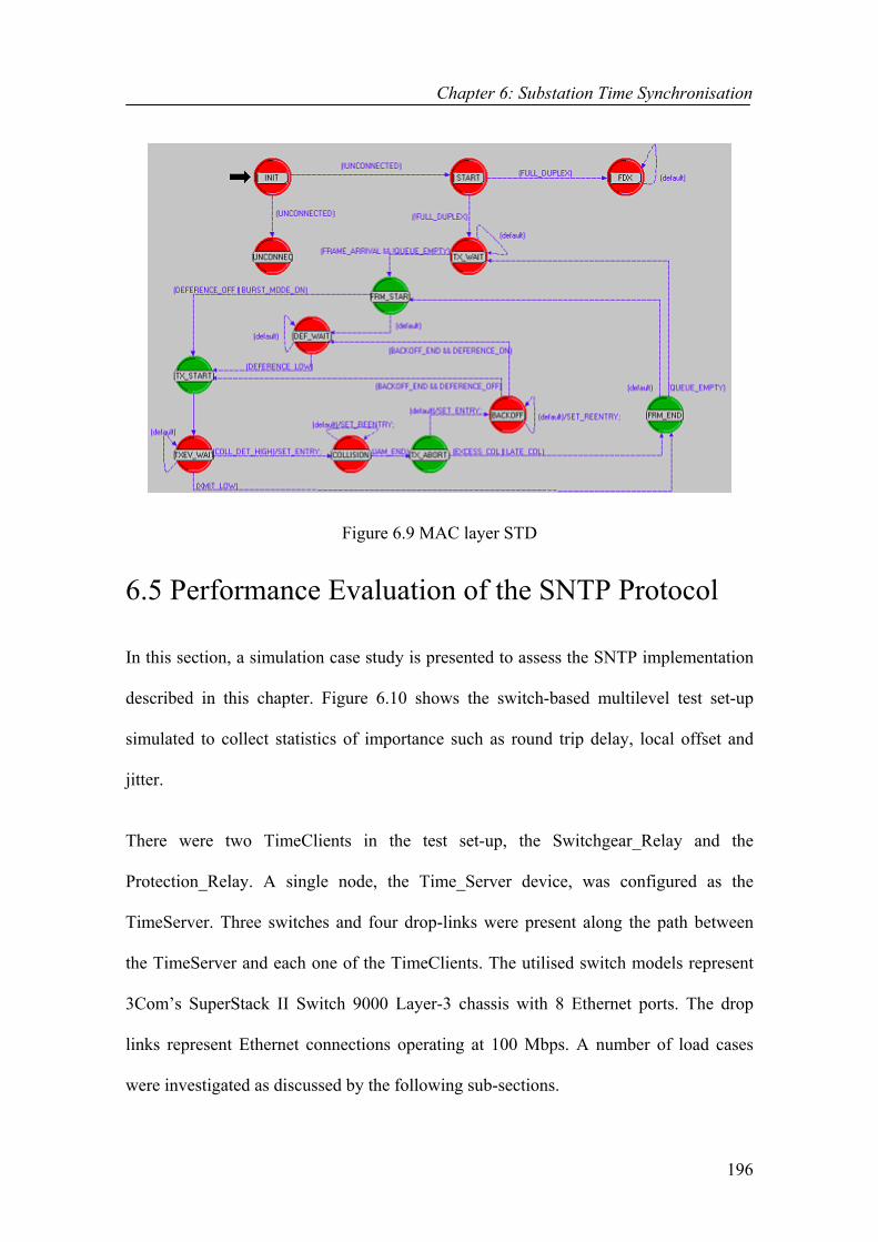
Chapter 6: Substation Time Synchronisation
196
Figure 6.9 MAC layer STD
6.5 Performance Evaluation of the SNTP Protocol In this section, a simulation case study is presented to assess the SNTP implementation
described in this chapter. Figure 6.10 shows the switch-based multilevel test set-up
simulated to collect statistics of importance such as round trip delay, local offset and
jitter.
There were two TimeClients in the test set-up, the Switchgear_Relay and the
Protection_Relay. A single node, the Time_Server device, was configured as the
TimeServer. Three switches and four drop-links were present along the path between
the TimeServer and each one of the TimeClients. The utilised switch models represent
3Com’s SuperStack II Switch 9000 Layer-3 chassis with 8 Ethernet ports. The drop
links represent Ethernet connections operating at 100 Mbps. A number of load cases
were investigated as discussed by the following sub-sections.

Chapter 6: Substation Time Synchronisation
197
Figure 6.10 Multilevel test set-up
6.5.1 No load case In this case, the network shown in Figure 6.10 was simulated with no other traffic other
than the TS traffic. The simulation duration was 30 seconds and each one of the
TimeClients was configured for sending time request packets to the TimeServer. Figure
6.11 shows the amount of SNTP traffic received and sent by the Protection_Relay in
bytes per second whilst Figure 6.12 shows the round trip delay and local clock offset
calculated in the Protection_Relay based on the received timestamps.
The round-trip delay was observed to be steady at 0.2 ms and the amount of offset
calculated did not exceed ± 1µs as illustrated in Figure 6.12. As a matter of fact, they all
turned out to be zeros in this no-load case. In a simulation such as this where the
simulation runs on a single operating system, all the nodes in the simulated network
have the same clock. Although they can be manually set to different clocks, this was not
experienced in this study since the main focus was on the timing accuracy.
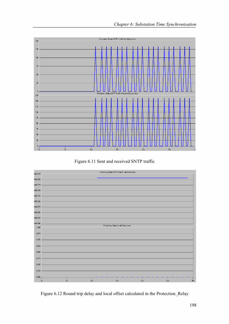
Chapter 6: Substation Time Synchronisation
198
Figure 6.11 Sent and received SNTP traffic
Figure 6.12 Round trip delay and local offset calculated in the Protection_Relay

Chapter 6: Substation Time Synchronisation
199
Ideally, all the calculated offset values are anyhow expected to be zeros in such a
simulation since the TimeServer and TimeClients’ clocks are already synchronised.
Therefore, the calculated offset values indicate the effect of the TS errors present in the
system reflecting the TS accuracy of the design. The results were pretty much as
expected pointing out the effectiveness of time stamping at the Ethernet driver level in
removing the effects of transmit and receive protocol stack delays on the TS accuracy.
The switch latency was not a major concern in this simulation case as the amount of
load through the switches was rather low. The main conclusion to derive is that IEC
class T5 timing accuracy of ± 1µs can easily be achieved in a network of 100 Mbps
Ethernet links with no other traffic but TS traffic when time stamping is carried out at
the Ethernet driver level.
6.5.2 5% load case
This simulation case presents a situation when 5 % of the bandwidth of the Time_Server
drop link was filled with dummy packets of 1000 bytes. The Time_Server drop link was
100 BASE-T, therefore the duration of the dummy packet was 1.6 ms. Figure 6.13
shows the round trip delay and local clock offset calculated in the Protection_Relay
based on the received timestamps. The results depicted in Figure 6.13 are significantly
different from the results of the no-load case. To begin with, the round trip delay varies
in between 0.2 and 0.35 ms primarily due to the variable switch latency. Finally, the
calculated local offset varies in between -40 and 50 µs. Although the offset values were
ideally expected to be zeros, they were calculated as non-zero values indicating the
presence of TS errors in the network. Figure 6.14 shows the queuing delay of
transmitter #2 of Switch 5, which is one of the components of the total switch latency.

Chapter 6: Substation Time Synchronisation
200
Figure 6.13 Round trip delay and local offset calculated for the 5 % load case
Figure 6.14 Switch 5 queuing delay

Chapter 6: Substation Time Synchronisation
201
The switch latency of Ethernet packets to the Time_Server was dependent on other
traffic sent to the Time_Server. This is clearly demonstrated in Figure 6.14, which
illustrates how the queuing delay increased when extra load through the switch was
present. Other components of the switch latency such as the Switch MAC delay were
also affected in a similar manner. Furthermore, having multiple switches on the path
between the TimeClients and TimeServer further imposed additional jitter worsening
the variable message delivery delay times. These sources of errors deteriorated the TS
accuracy as illustrated in Figure 6.13 where it is shown that only the IEC class T2
timing accuracy of ± 0.1ms can be achieved in such a network without the use of any
filtering mechanisms. Hence, the need for the use of filtering mechanisms in eliminating
the effect of variable switch latency was once more comprehended.
Figure 6.15 shows the case where the clock filter procedure was used to deal with the
variable switch latency selecting the set of filtered values corresponding to the
minimum synchronisation distance. It displays both the filtered and un-filtered local
offset values. As illustrated in Figure 6.15, some of the offset values (indicated by the
blue dots) calculated in the Protection_Relay do fall on the 0 µs line (in the vicinity of 0
µs --- ± 0.5 µs) while some others vary in between -40 and 50 µs. On the other hand, the
filtered offset values (indicated by the red dots) that are the end products of the clock
filter procedure all lay on the 0 µs line (± 0.5 µs). This indicates the effectiveness of the
clock filter procedure in choosing the best sample set corresponding to the minimum
synchronisation distance. When the first SNTP message reply arrived at the
Protection_Relay, the time stamps were recorded as T1: 10.000003s, T2: 10.000096s,
T3: 10.000109s and T4: 10.000201s. Subsequently, the first data set sample (θ, δ, ε)
(0.5µ, 0.00211, 1.000200686) was calculated as follows and shifted into the filter.

Chapter 6: Substation Time Synchronisation
202
RTD = δ = 10.000201 -10.000003 -10.000096 + 10.000109 = 0.000211s
LCO = θ = (10.000096 -10.000003 +10.000109 -10.000201)/ 2 = 0.5 µs
1.0003061 2
0.000211 61.00020068 2
|| =+=+=δελ
For all subsequent messages, the new sample sets were also calculated and inserted into
the filter. Nevertheless, the filtered clock offset was always chosen as the clock offset of
the first set, i.e. 0.5µ, as λ calculated from the first set was the lowest. In a much heavily
loaded network, the switch latency problem will unquestionably deteriorate. However, it
shall still be possible to bring the TS accuracy within the acceptable bounds since, as
illustrated by this simulation study, not all the data set samples are affected by the
variable switch latency. Consequently, the main conclusion to derive from this
simulation case is that the IEC class T5 timing accuracy of ± 1µs can be achieved in
medium or heavily loaded networks only with the proper use of the NTP filtering
mechanism employed to eliminate the effect of the variable switch latency.
Figure 6.15 Filtered and un-filtered local offset values
Chapter 6: Substation Time Synchronisation
203
6.6 Conclusion In this chapter, the design and implementation of SNTP client and server applications
and their incorporation into the overall communication architecture has been presented.
The need for TS in substation applications was revealed in Chapter 5 when discussing
the general communication related requirements of the IEC 61850 standard. This
chapter has focused on the concept of TS in further detail proposing the implementation
of a stand-alone IEC 61850 TimeServer and integration of SNTP client applications into
the ACSI application layer modules of Chapter 5. The proposed study has illustrated
how the SNTP TS protocol can be incorporated into the overall design to harmonise the
local clocks of the communicating IEDs within a substation network such that sensing
and actuation of time-sensitive data can be coordinated accurately across multiple
nodes.
The IEC 61850 standard stresses on different levels of TS accuracy requirements,
ranging from 1ms to 1µs, for different protection functions within a substation. This
chapter has demonstrated how the SNTP protocol can be sufficient enough for
achieving all the TS accuracy requirements by a means of time stamping at the MAC
layer and with the use of an adaptive filtering technique. It has been shown that the
protocol stack delays can be diminished by time stamping at the Ethernet driver level
leading to a better TS accuracy. The simulations have also revealed that the class T5
requirement is much harsher and can hardly tolerate any jitter within the infrastructure
as a result of increased switch load. Nevertheless, the use of the NTP adaptive filtering
mechanism to eliminate the effect of jitter has been demonstrated to be sufficient
enough in achieving the class T5 requirement.

Chapter 7: Hardware in the Loop Modelling & Simulation
204
Chapter 7 Hardware in the Loop Modelling & Simulation
7.1 Introduction
In this chapter, the methodology of incorporating Commercial off-the Shelf (COTS)
network hardware into the OPNET Modeller for “Hardware in the Loop” modelling and
simulation is described. The discussed methodology simply involves the design and
implementation of unique gateway models in OPNET enabling the OPNET software to
transmit messages to other simulations running on separate machines over a real
network and also to receive messages back from them over the same network. A
preliminary implementation is presented which allows for the testing of an ACSI
request-reply interaction in an application where two nodes exist: An ACSI client, an
ACSI server and client/server interactions between these.
The chapter starts in Section 7.2 with an overview of the “Hardware in the Loop”
methodology. Then in Section 7.3, the design and implementation details of the gateway
modules are discussed while Section 7.4 presents the “Hardware in the Loop”
simulation carried out to validate the designed gateway models and demonstrate the
testing of an ACSI request-reply interaction over a real Ethernet network. The
conclusions of this chapter are given in Section 7.5.

Chapter 7: Hardware in the Loop Modelling & Simulation
205
7.2 Hardware in the Loop Capability This chapter presents the design and implementation of a “Hardware in the Loop”
(HITL) capability within the discrete-event modelling package, the OPNET Modeller.
The objective is to develop such a capability that will enable the testing and
performance measurements of various components designed and implemented in this
project over a real network.
The HITL is a real Ethernet network that is interfaced with C language coded process
models designed and implemented in OPNET. The ambition is to run two separate
simulations on two different Personal Computers (PCs) as illustrated in Figure 7.1, e.g.
an ACSI client on one machine and an ACSI server on another, and link them both over
the real Ethernet communication network that exists between the two machines.
Router
Switch
Switch
Firewall
Simulation running on computer A Simulation running on computer B
Figure 7.1 Simulations linked through a real network
Several communication devices such as routers, switches and firewalls might exist in
the path between two PCs (in the simulation loop of the OPNET models) depending on
Chapter 7: Hardware in the Loop Modelling & Simulation
206
the network architecture. Therefore, it will not be an exaggeration if it is claimed that
several real network devices are being interfaced. However, the internal network
structure is not a major concern in this study since any two or more devices within a
network with IP addresses must be able to communicate amongst each other regardless
of the network architecture.
7.3 Design and Implementation of the HITL Model The main focus in this section is on describing the design and implementation of the
HITL model. The objective has resulted in the design and implementation of two
process models using OPNET as the software. The first process model has been
implemented in a node as a gateway for ACSI clients while the second as a gateway for
ACSI servers. The designed process models have two main tasks as outlined below:
1. They translate the OPNET packets they receive from other nodes running in
the simulation into IP packets and forward them to the transport layer of the
PC for transmission to the real network, and
2. They translate the IP packets received from the real network into OPNET
packet structures and discrete events transmitting them to their destination
nodes in the simulation.
The possibility of a HITL simulation in OPNET was first recognised after reading the
references [137, 138]. Although the models to be discussed in this chapter use the same
basic theories discussed in references [137, 138], they have been uniquely modelled and
implemented. In references [137, 138], models have been proposed that provide the
capacity of interfacing to a real network through the UDP/IP transport layer. The unique
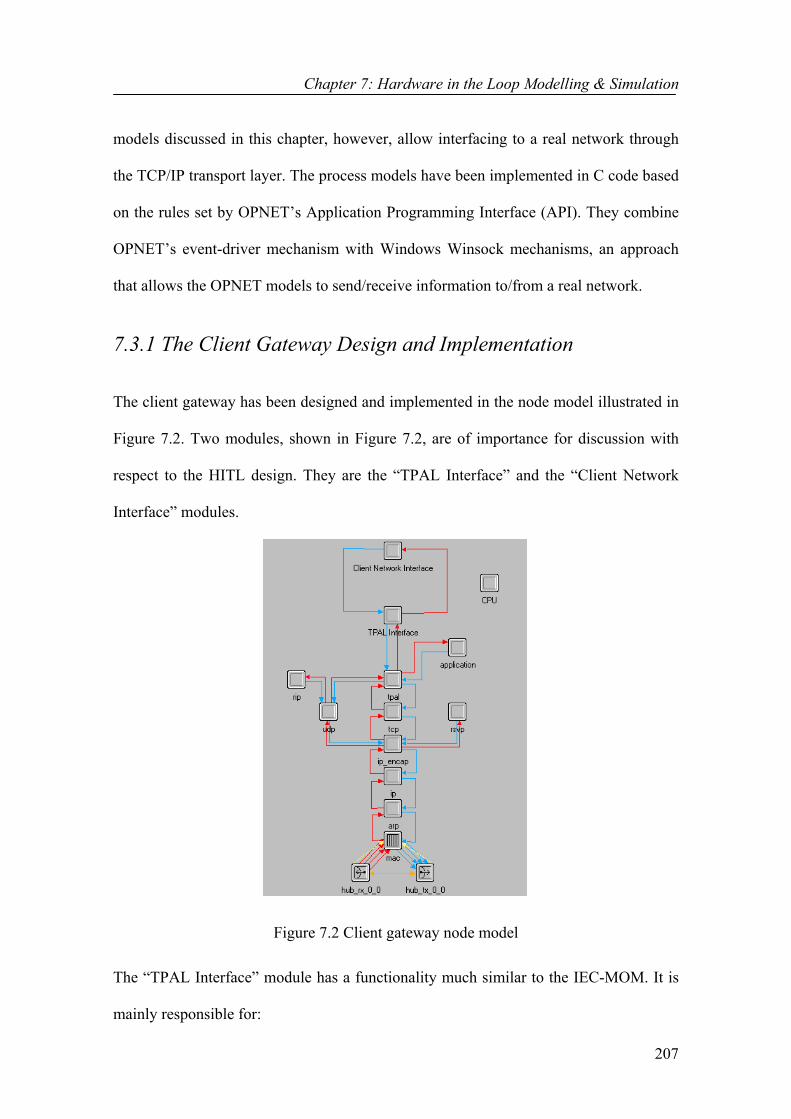
Chapter 7: Hardware in the Loop Modelling & Simulation
207
models discussed in this chapter, however, allow interfacing to a real network through
the TCP/IP transport layer. The process models have been implemented in C code based
on the rules set by OPNET’s Application Programming Interface (API). They combine
OPNET’s event-driver mechanism with Windows Winsock mechanisms, an approach
that allows the OPNET models to send/receive information to/from a real network.
7.3.1 The Client Gateway Design and Implementation The client gateway has been designed and implemented in the node model illustrated in
Figure 7.2. Two modules, shown in Figure 7.2, are of importance for discussion with
respect to the HITL design. They are the “TPAL Interface” and the “Client Network
Interface” modules.
Figure 7.2 Client gateway node model
The “TPAL Interface” module has a functionality much similar to the IEC-MOM. It is
mainly responsible for:
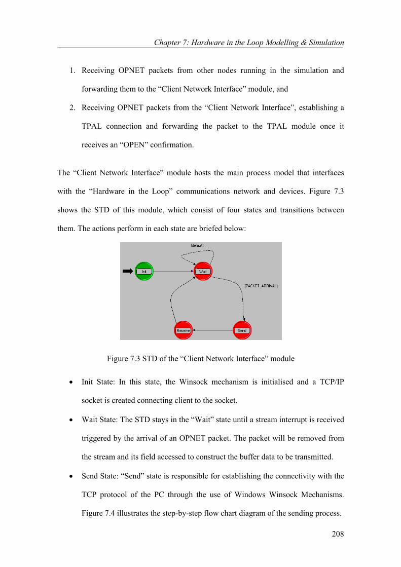
Chapter 7: Hardware in the Loop Modelling & Simulation
208
1. Receiving OPNET packets from other nodes running in the simulation and
forwarding them to the “Client Network Interface” module, and
2. Receiving OPNET packets from the “Client Network Interface”, establishing a
TPAL connection and forwarding the packet to the TPAL module once it
receives an “OPEN” confirmation.
The “Client Network Interface” module hosts the main process model that interfaces
with the “Hardware in the Loop” communications network and devices. Figure 7.3
shows the STD of this module, which consist of four states and transitions between
them. The actions perform in each state are briefed below:
Figure 7.3 STD of the “Client Network Interface” module
• Init State: In this state, the Winsock mechanism is initialised and a TCP/IP
socket is created connecting client to the socket.
• Wait State: The STD stays in the “Wait” state until a stream interrupt is received
triggered by the arrival of an OPNET packet. The packet will be removed from
the stream and its field accessed to construct the buffer data to be transmitted.
• Send State: “Send” state is responsible for establishing the connectivity with the
TCP protocol of the PC through the use of Windows Winsock Mechanisms.
Figure 7.4 illustrates the step-by-step flow chart diagram of the sending process.

Chapter 7: Hardware in the Loop Modelling & Simulation
209
• Receive State: Once a request has been sent by the “Send” state, the process
moves into the “Receive” state where it waits for the arrival of the reply packet.
Figure 7.5 illustrates the flow chart diagram of the receiving process.
Initialise temporary variables to be used in the"Send" state
Fill in the address structure for the destinationserver
Write the buffer containing the data to betransmitted to the transmission queue
TCP removes the data from the transmissionqueue, constructs a TCP packet and forwards
it to IP
START
IP creates an IP packet and forwards it to theData Link layer and then to the Physical Layer
The resulting packet is transmissted to itsdestination
STOP
Figure 7.4 Flowchart diagram of the client’s sending process
Initialise temporary variables to be used in the
"Receive" state Wait for the arrival of the request packet
When the real request packet arives, pull itfrom the TCP socket
Extract the fields and attributes of the realpacket
START
Construct a virtual OPNET packet using theextracted fields and attributes
Send the virtual packet to the underlying"TPAL Interface" module to be transmitted to
other virtual devices
STOP
Figure 7.5 Flowchart diagram of the client’s receiving process
7.3.2 The Server Gateway Design
The server gateway has been designed and implemented in the node model illustrated in
Figure 7.6. The “Server Network Interface” module is significantly different from the

Chapter 7: Hardware in the Loop Modelling & Simulation
210
“Client Network Interface” module. Its main difference is that it waits for the arrival of
a request packet from the network rather than initiating the transfer of one.
Figure 7.6 Server gateway node model Figure 7.7 shows the STD of the “Server Network Interface” which has been
implemented in a processor module. It consists of 3 states and transitions between these.
Figure 7.7 STD of the “Server Network Interface” module The actions performed in each state are briefed below:
• Init State: In this state, the Winsock mechanism is initialised and a TCP/IP
socket is created binding server to the socket.

Chapter 7: Hardware in the Loop Modelling & Simulation
211
• Receive State: In this state, the process waits for the arrival of a real request
packet from the network. Figure 7.8 illustrates the step-by-step flow chart
diagram of the server’s receiving process.
• Send State: In this state, the process waits for the arrival of a virtual reply packet
from other virtual nodes in the simulation. Figure 7.9 illustrates the step-by-step
flow chart diagram of the server’s sending process.
Initialise temporary variables to be used in the"Receive" state
Wait for the arrival of the real request packetWhen the real packet arives, pull it from theTCP socket
Extract the fields and attributes of the realpacket
START
Construct a virtual OPNET packet using theextracted fields and attributes
Send the virtual request packet to theunderlying "TPAL Interface" module to be
transmitted to other virtual devices
STOP
Listen on the socket & accept connections
Figure 7.8 Flowchart diagram of the server’s receiving process
Initialise temporary variables to be used in the
"Send" state Wait until the virtual reply packet arrives
Write the buffer containing the data to betransmitted to the transmission queue
TCP removes the data from the transmissionqueue, constructs a TCP packet and forwards
it to IP
START
IP creates an IP packet and forwards it to theData Link layer and then to the Physical Layer
The resulting packet is transmissted to itsdestination
STOP
Remove the packet from the input streamextract its fields to be used when constructingthe buffer containing the data to be transmitted
Figure 7.9 Flowchart diagram of the server’s sending process

Chapter 7: Hardware in the Loop Modelling & Simulation
212
7.4 Hardware in the Loop Simulation This section mainly discusses the simulation scenario that was carried out to justify the
accurate operation of the designed HITL capability and testing of an ACSI request-reply
interaction over a real Ethernet network. Figure 7.10 shows the test set-up that was used
for this purpose. It shows two different simulation windows running on two different
machines being linked together through the use of the HITL capability. An ACSI client,
the Station_Unit, was configured in a simulation window running on the PC in room
D706 while an ACSI server, the Protection_Relay, was configured in a simulation
window running on another PC in room D704. The Client_Gateway device hosts the
client gateway model and the Server_Gateway device hosts the server gateway model.
OPNET Computer in D706D706-3
OPNET Computer in D704D704-5
Packets from D704-5 to D706-3
Packets from D706-3 to D704-5
Figure 7.10 HITL simulation test set-up
Figures 7.11 and 7.12 show the event-by-event simulation summaries received on two
different simulation consoles. A client/server service request was primarily being tested
where the Station_Unit issued a “GetLogicalDeviceDirectory” request to the
Protection_Relay. Once the ACSI request arrived at the Client_Gateway, its information
content was forwarded to the physical network in a real IP packet. The Server_Gateway

Chapter 7: Hardware in the Loop Modelling & Simulation
213
removed the information from the IP packet on its arrival and constructed a virtual
OPNET packet, which was sent to the Protection_Relay device. When the
Protection_Relay received the ACSI request, it executed the relevant service before
creating an ACSI reply packet, to be forwarded to the Server_Gateway. Similarly, the
Server_Gateway put the ACSI reply data on the network in a real IP packet that was
later picked up by the Client_Gateway and forwarded to the Station_Unit device in a
virtual OPNET packet. Station_Unit displayed the output parameters returned in the
ASCI reply message before destroying the packet.
Figure 7.11 Simulation console output of D704-5 computer
Figure 7.12 Simulation console output of D706-3 computer
The application-to-application delay times for the request and reply packets were
measured to be about 50 ms much higher than what was expected. The large size of the

Chapter 7: Hardware in the Loop Modelling & Simulation
214
data (800 bytes) that gets transmitted to the real network and especially the fact that two
PCs could not be perfectly time synchronized are believed to be amongst the factors that
have contributed to such large delay times. Once the HITL capability is extended to
include support for the time synchronisation model of Chapter 6 after when the
communicating devices can be better time synchronized, it is believed that much more
accurate delay times will be able to be measured.
7.5 Conclusions In this chapter, the design and implementation of a “Hardware in the Loop” capability
within the OPNET Modeler software package has been presented. The “Hardware in the
Loop” is a real network component that can be interfaced with the OPNET models
using process models coded in the C language and Windows Winsock mechanisms. The
main objective has been on the design and implementation of gateway models with a
capability of translating OPNET discrete events into IP packets and IP packets into
OPNET discrete events. As a result, several new processor modules were designed and
implemented that has enabled the construction of client and server gateway models.
In this chapter, the performance testing of an ACSI client/server application has been
carried out over a real Ethernet network making use of the newly implemented gateway
models and results have been illustrated to validate the proper function of the gateway
components and the HITL capability. It is possible to extend the HITL capability
described in this chapter with the capability of interfacing to a real network through the
UDP/IP transport layer as well as support for multicast transmission. After then more
detailed simulations can be carried out to further test the implemented IEC 61850
standard over a real network including its data exchange services such as the GOOSE.

Chapter 8: Conclusions and Future Developments
215
Chapter 8 Conclusions and Future Developments
8.1 Introduction This chapter details with the major findings and accomplishments of this work and how
the work has addressed the aims proposed in Chapter 1. Also, it presents the conclusions
that are drawn from the findings as well as the limitations in this work. Future research
options are also outlined in this chapter.
With distributed substation systems becoming increasingly large-scale and dynamic, the
interest on the Substation Automation (SA) concept has increased substantially over the
last decade. The primary objective of SA is to improve operations, maintenance and
efficiencies in the substation environment. The use of effective communication
techniques to link the various control, monitoring and protection elements within a
substation is a critical factor in determining the success of a SA system. The recent
developments of the SA communication standards, i.e. the UCA 2.0 and IEC 61850
standards, are clear indications of the importance of communication in achieving the
goals of SA. UCA 2.0 and IEC 61850 target the standardisation of the language of
communication between the devices of a SA system. Standardisation is regarded as the
key for the advancement of the connectivity and interoperability within such systems.

Chapter 8: Conclusions and Future Developments
216
Moreover, the need for the further advancement of an open and standard substation
working environment has lead to increased research activity in the communication
techniques and principles employed to make distributed substation systems more robust,
reliable, high-speed and secure.
In this thesis, research on the implementation of the IEC 61850 communication standard
as a concrete application layer protocol has been presented. The thesis has addressed
major challenges and several key issues related to the transformation of IEC 61850 from
an abstract nature into a tangible structure. It was argued that the implementation of IEC
61850 making use of the techniques of Object-Oriented Programming (OOP) is very
valuable in amplifying the understanding of the standard and simplifying its use through
the Object-Oriented (OO) development of its information and information exchange
service models.
The work described in this thesis has also addressed an important issue that highlighted
the significance of having proper middleware support to manage the communication
needs of the IEC 61850 standard in a scalable and efficient way and all without
compromising traditional middleware features. In view of that, a Message-Oriented
Middleware (MOM) architecture as part of a communication processor protocol stack
has been designed and implemented. The designed MOM architecture, the IEC-MOM
middleware, represents a unique stand-alone communication interface to IEC 61850
application layers incorporating various communication models and techniques for
reliable and fast message dissemination.
Major findings of this thesis, results and novel ideas have been reported in related
publications in ‘List of Publications’ section of this thesis. Section 8.2 of this chapter
Chapter 8: Conclusions and Future Developments
217
presents a general overview of the specific tasks carried out to achieve a successful
completion of this research and describes how the accomplished work has addressed the
aims outlined in Chapter 1. Last of all, Section 8.3 details the future research options
and possible extensions that can be applied to the study described in this thesis.
8.2 Summary The thesis began in Chapter 2 with an overview of substation automation, integration
and communication concepts. The focus was on describing the desire and the need of
achieving connectivity and interoperability in SA systems through the use of
standardised application and communication protocols. Subsequently, some of the
physical and application layer protocols that have found widespread use in substation
communication systems over the past decade were re-examined and the recently
evolved SA standards, UCA 2.0 and IEC 61850, were introduced to the reader. Various
middleware architectures were also investigated in Chapter 2, which helped to structure
the design space in terms of architecture, components, reliability, speed and services.
One of the primary objectives in this research was the OO implementation of the IEC
61850 Abstract Communication Service Interface (ACSI) Object and Service Models
(OSMs) as concrete programs. Accordingly, in this thesis, Chapters 3 and 4 presented
the development of the IEC 61850 application and device view OSMs describing how
they can be built based on their descriptions in the IEC 61850 documentation. The
research described in Chapters 3 and 4 has further enhanced the understanding of the
IEC 61850 standard by illustrating how the OO models discussed in the standard can as
well be implemented using the techniques of OOP and provided an alternative to the
current implementation approach adopted by IEC 61850 that is the mapping process. A

Chapter 8: Conclusions and Future Developments
218
standard universal OO implementation of the IEC 61850 standard has been proposed
that makes it possible to fully isolate the standard’s implementation process from any
underlying communication service and remove its dependency on the mapping process
Then, in Chapter 5, the design and implementation of a communication processor
architecture was presented. The designed architecture consists of application layer
modules built on top of a middleware architecture running on protocol stack that
incorporates the TCP/UDP-IP network protocols. The proposed application layer
modules enable the configuration of ACSI client and server applications at the
application layer of a communication processor based on the OO implemented models
of the standard itself rather than the use of the existing implemented models of another
application layer protocol referred to as the mapping process.
Chapter 5 additionally described the layered architecture, components and principles of
the IEC-MOM middleware and an example prototype implementation was given. The
performance of the designed middleware architecture was evaluated in the remainder of
Chapter 5 with the help of broad simulations, which demonstrated the effectiveness of
the designed middleware in incorporating various communication techniques such as
unicast and multicast on a single platform providing a comprehensive communication
service to the IEC 61850 application layer protocol. The simulations showed that the
designed middleware architecture can be used effectively to provide necessary
communication services to ACSI clients and servers adding only nominal overhead to
the underlying protocol stack. It was demonstrated that timely and reliable transmission
of GOOSE messages can be achieved with the aid of a trade-off mechanism that
retransmits GOOSE messages a few times whilst not exterminating the 4 ms timing

Chapter 8: Conclusions and Future Developments
219
determinism. Finally, a more realistic network loading case was examined where the
accurate workings of the GOOSE and SV models of Chapter 4 were verified and it was
shown that the designed architecture is capable of meeting the timing determinism and
reliability concerns even in the case of GOOSE and SV messages both being
simultaneously transmitted over the same communication channel.
Chapter 6 addressed the design and implementation of SNTP client and server
applications and their incorporation into the communication processor architecture.
SNTP was demonstrated to be adequate in achieving all the Time Synchronisation (TS)
accuracy requirements set by IEC 61850 by a means of time stamping at the MAC layer
and with the use of an adaptive filtering technique. The technique of time stamping at
the Ethernet driver level was shown to be effective in diminishing the protocol stack
delays leading to better TS accuracies. Furthermore, Chapter 6 revealed the prospect of
eliminating the effect of jitter through the use of the NTP adaptive filtering mechanism
in order to achieve the class T5 requirement, which is much harsher and can hardly
tolerate any jitter within the infrastructure as a result of increased switch load
Finally, Chapter 7 presented the design and implementation of a “Hardware in the
Loop” (HITL) capability within the OPNET Modeller software package. The proposed
HITL capability acts as a gateway between the simulation environment and the real
Ethernet network establishing a link between the virtual simulation and the real network
whilst permitting for the testing and evaluation of all the designed components over a
real network. Chapter 7 also described the performance testing of an ACSI request-reply
interaction that was carried out making use of the implemented gateway models and
results were illustrated to validate the designed HITL capability.
Chapter 8: Conclusions and Future Developments
220
8.3 Future Work
This section discusses the limitations of the work described in this thesis and details the
future research options and possible extensions that can be applied.
While discussing substation TS in Chapter 6, the synchronisation of substation nodes
relative to a TimeServer was looked into excluding the process of externally
synchronising the TimeServer’s local clock relative to a real-time clock. A possible
future extension to this part of this research would be the modelling and implementation
of a real-time clock such as a GPS device to take into account the process of external
synchronisation. Then in Chapter 7, the developed HITL capability was limited to a
client/server model where interfacing to a real network was restricted to the use of the
TCP/IP transport layer. Extending the HITL capability with the capability of interfacing
to a real network through the UDP/IP transport layer as well as support for multicast
transmission and TS are the possible future research options that need to be explored.
The expansion of the HITL capability in the described manner will allow for the
advanced testing of the implemented IEC 61850 communication standard over a real
network including its information exchange service models such as the GOOSE and SV
models. The incorporation of the TS model into the HITL capability will furthermore
make it possible to time synchronise the communicating devices enabling more accurate
statistic gathering.
In the project described in this thesis, no security measures have been considered
whatsoever. Nevertheless, the extension of the overall design and implementation with
security measures in accordance with the security measures described in IEC 62351-6 is
a potential research avenue and any future work to be carried out in this field shall

Chapter 8: Conclusions and Future Developments
221
reflect on such changes. The remainder of this section covers the consideration of cyber
security in the electric power industry as outlined by the IEC Technical Committee (TC)
57 Working Group (WG) 15.
The use of automated control systems and microprocessor based protection systems in
the electric power industry along with the need to provide remote access into these
systems has increased the risk of these systems being vulnerable to unauthorized hostile
access. The extension of communication networks out to the substation has magnified
the possibility of cyber attacks ranging from espionage to sabotage via electronic
intrusion and computer hacking [139]. However, the electric power industry has long
been aware of this threat and taken the necessary steps to reduce risk and mitigate
vulnerabilities. IEC report 62210 [140] “Data and Communications Security”, a report
developed and circulated throughout the IEC in 1999 and published in 2003, has lead to
the establishment of the IEC WG 15 titled “Power System Control and Associated
Communications - Data and Communications Security” to look across the other
working groups to address end-to-end security recommending or supplying standardized
security enhancements as needed [141, 142]. Securing application-to-application
information exchange through supplying strong authentication, message integrity and
confidentiality (e.g. encryption) enhancements as well as Spoof/Replay protection to the
IEC TC 57 protocols is the main focus of the WG 15.
A new document known as IEC 62351 [143] incorporates many of the new work items
currently under development by IEC TC 57 WG 15. The IEC 62351 document consists
of seven main sections and includes security considerations for profiles including
TCP/IP, MMS, IEC 60870-5 and IEC 61850.

Chapter 8: Conclusions and Future Developments
222
The fact that many TC 57 communication profiles including IEC 61850 ACSI over
TCP/IP and IEC 60870-5-104 are based on the TCP/IP has resulted in the need for a
common security solution to be investigated for profiles using TCP/IP. IEC 62351-3
specifies the use of Transport Layer Security (TLS) in order to secure IEC TC 57
protocols over the Internet. Likewise, IEC 62351-4 includes security considerations for
profiles that include the MMS. The addition of application-level authentication through
the use of TLS’s authentication measures is the main suggestion.
Security enhancements are also required when implementing and using communication
profiles of IEC 61850 in non-secure environments. The basic design principles are that
secure and non-secure profiles must be able to unambiguously co-exist with a single set
of identity management policies for all profiles using mainstream IT methodologies.
The main security objective is to prevent eavesdropping and spoofing/playback of
captured data from non-trusted entities as well as assuring authorized access even within
a closed private network. Security for five IEC 61850 profiles: Client/Server, GOOSE,
GSSE, GSSE management and Sample Measured values (SMV) have been developed
and packaged into IEC 62351-6. TLS encryption is used for Client/Server profiles
where the data is encrypted so that only the two communicating entities can understand
the data. For the peer-to-peer multicast profiles such as GOOSE, encryption is not
acceptable since it affects the strict transmission rates required for multicast datagrams.
Hence, authentication is the only security measure included for those where digital
signatures are used ensuring that the entity at the other end is known and trusted [144,
145].

References
223
References
[1] IDC Technologies Website, “Practical Distribution & Substation Automation for
Electrical Power Systems (EU),” Web Doc., viewed November 2005. [Online].
Available: http://www.idc-online.com/training courses/electrical engineering/?code=E
U&country=United+Kingdom
[2] Kreiss Johnson Technologies Website, “Solutions: Value Events Drive Profitable
Action,” Web Doc., viewed May 2005. [Online]. Available: http://www.idc-onl
ine.com/training_courses/electrical_engineering/?code=EU&country=United+Kingdom
[3] PSE Incorporation Website, “Substation Automation and Integration,” Web Doc.,
viewed July 2005. [Online]. Available: http://www.powersystem.org/services/utilityaut
omation/substationautomation/substationautomation.aspx
[4] C. Strauss, “Practical Electrical Network Automation and Communication Systems,”
ISBN: 0750658010, Ed. Great Britain: Newnes, 2003.
[5] IEC 61850 Website, “IEC 61850 Communication Networks and Systems in
Substations,” Web Doc., viewed May 05. [Online]. Available: http://www.61850.com/
[6] ObjectWeb Consortium Website, “What is Middleware,” Web Doc., viewed June
2005. [Online]. Available: http://66.102.7.104/search?q=cache:pfkohQJSB7oJ:mIddle
ware.objectweb.org/+%22middleware+is%22&hl=en
[7] Q. H. Mahmoud, “Middleware for Communications,” ISBN: 0470862068, Ed.
England: John Wiley and Sons, 2004.
[8] Power Measurement Ltd., “Application Note: Integrated Substation Automation
using an EEM System,” ION White Paper, Canada, February 2004. [Online]. Available:
http://www.pwrm.com/library/literature/application_notes/Substation_Auto mation.pdf

References
224
[9] EPRI, “Utility Communications Architecture (UCA),” Version 2.0, EPRI Standard
TP-114398, October 1999.
[10] IEC-TC 57, “Communication networks and systems in substations - Part 1:
Introduction and overview,” IEC Standard IEC/TR 61850-1, Edition 1.0, 2003.
[11] D. Baigent, M. Adamiak, and R. Mackiewicz, “IEC 61850 Communication
Networks and Systems in Substations: An Overview for Users,” Web Doc., SISCO
Systems, 2003, viewed June 2005. [Online]. Available: www.sisconet.Com/downloads/
IPSEP%202004%20IEC%2061850%20Overview%20for%20Users.ppt
[12] M. Bartoll, “Control and Automation of Electricity Transmission and Distribution,”
Department of Computer Science, Mälardalen University, Västerås, Sweden, September
2004. [13] P. R. Pietzuch, “Hermes: A Scalable Event-Based Middleware,” PhD Thesis, ISSN
1476-2986, Queens' College, University of Cambridge, 2004.
[14] M. Ostertag, G. Hilpert and T. Kern, “Article: The Standard Route to Ethernet-
Based Substation Automation,” The Industrial Ethernet Book, Issue 15, pp. 34, June
2003.
[15] E. Udren, S. Kunsman and D. J. Dolezilek, “Significant Substation Communication
Standardization Developments,” Schweitzer Engineering Laboratories (SEL), Pullman,
Washington, 2000. [Online]. Available: http://www.Selinc.com/techpprs/ 6105.pdf [16] K. C. Behrendt and M. J. Dood, “Substation Relay Data and Communications,”
SEL, Pullman, Washington, 2000. [Online]. Available: http://www.selinc.com
[17] D. J. Dolezilek, and D. A. Klas, “Using Information from Relays to Improve
Protection,” Schweitzer Engineering Laboratories (SEL), Pullman, Washington, pp.1-7,
1999. [Online]. Available: http://www.selinc.com/techpprs/6080.pdf
[18] D. J. Dolezilek, “Understanding, Predicting and Enhancing the Power System
through Equipment Monitoring and Analysis,” SEL, Pullman, Washington, pp.1-6,
1998. [Online]. Available: http://www.selinc.com/techpprs/6104.pdf
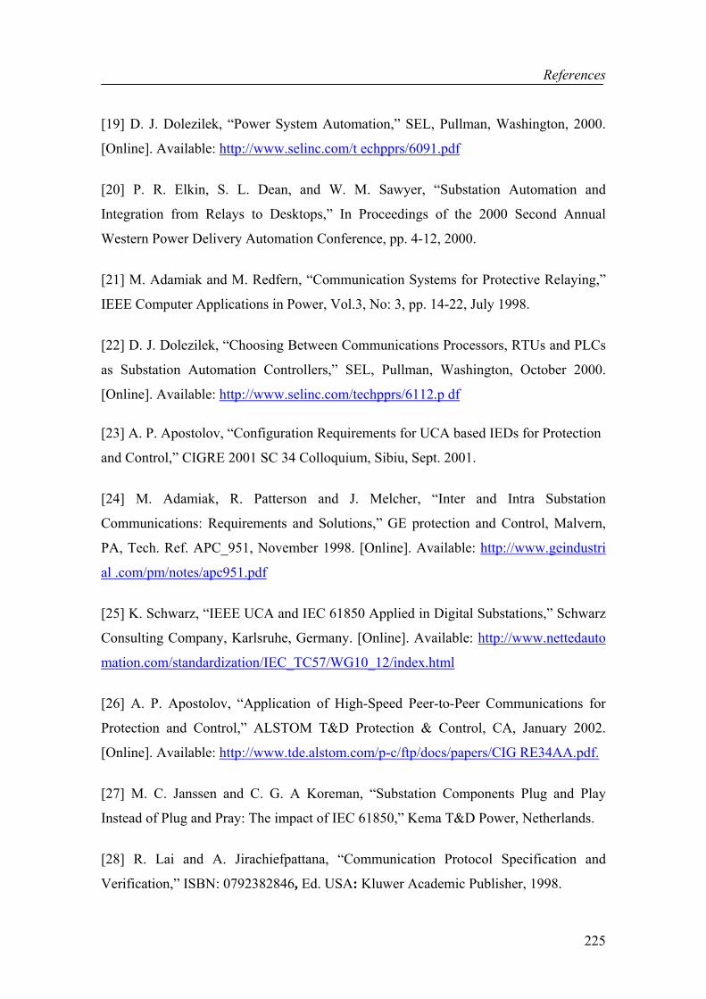
References
225
[19] D. J. Dolezilek, “Power System Automation,” SEL, Pullman, Washington, 2000.
[Online]. Available: http://www.selinc.com/t echpprs/6091.pdf
[20] P. R. Elkin, S. L. Dean, and W. M. Sawyer, “Substation Automation and
Integration from Relays to Desktops,” In Proceedings of the 2000 Second Annual
Western Power Delivery Automation Conference, pp. 4-12, 2000.
[21] M. Adamiak and M. Redfern, “Communication Systems for Protective Relaying,”
IEEE Computer Applications in Power, Vol.3, No: 3, pp. 14-22, July 1998.
[22] D. J. Dolezilek, “Choosing Between Communications Processors, RTUs and PLCs
as Substation Automation Controllers,” SEL, Pullman, Washington, October 2000.
[Online]. Available: http://www.selinc.com/techpprs/6112.p df
[23] A. P. Apostolov, “Configuration Requirements for UCA based IEDs for Protection
and Control,” CIGRE 2001 SC 34 Colloquium, Sibiu, Sept. 2001.
[24] M. Adamiak, R. Patterson and J. Melcher, “Inter and Intra Substation
Communications: Requirements and Solutions,” GE protection and Control, Malvern,
PA, Tech. Ref. APC_951, November 1998. [Online]. Available: http://www.geindustri
al .com/pm/notes/apc951.pdf
[25] K. Schwarz, “IEEE UCA and IEC 61850 Applied in Digital Substations,” Schwarz
Consulting Company, Karlsruhe, Germany. [Online]. Available: http://www.nettedauto
mation.com/standardization/IEC_TC57/WG10_12/index.html
[26] A. P. Apostolov, “Application of High-Speed Peer-to-Peer Communications for
Protection and Control,” ALSTOM T&D Protection & Control, CA, January 2002.
[Online]. Available: http://www.tde.alstom.com/p-c/ftp/docs/papers/CIG RE34AA.pdf.
[27] M. C. Janssen and C. G. A Koreman, “Substation Components Plug and Play
Instead of Plug and Pray: The impact of IEC 61850,” Kema T&D Power, Netherlands.
[28] R. Lai and A. Jirachiefpattana, “Communication Protocol Specification and
Verification,” ISBN: 0792382846, Ed. USA: Kluwer Academic Publisher, 1998.

References
226
[29] F. F. Driscoll, “Data Communications,” International Ed., Ed. Florida: Harcourt
Brace Jovanovich Publishers, pp. 233-235, 1992.
[30] G. J. Holzmann, “Design and Validation of Computer Protocols,” 2nd ed., Ed. New
Jersey: Prentice Hall, pp. 27-30, 1991.
[31] G. Held, “Ethernet Networks: Design, Implementation, Operation, Management,”
ISBN: 0470844760, 4th ed., Ed. Great Britain: John Wiley & Sons, pp. 51-59, 2002.
[32] C. E. Spurgeon, “Ethernet: The Definitive Guide,” ISBN: 1565926609, Ed. USA:
O”Reilly, pp. 1-22, February 2000.
[33] IEEE, “Information technology -- Telecommunications and information exchange
between systems -- Local and metropolitan area networks -- Specific requirements --
Part 3: Carrier sense multiple access with collision detection (CSMA/CD) access
method and physical layer specifications,” IEEE 802.3/ISO 8802-3, March 2002.
[34] D. Woodward, “The Hows and Whys of Ethernet Networks in Substations,”
Schweitzer Engineering Laboratories, Pullman, Washington, 2001. [Online] Available:
http://www.selinc.com/techpprs/6115.pdf.
[35] R. Haden, “Ethernet Basics,” Web Doc., CommsPlace Directory, viewed 02 June
2005. [Online]. Available: http://www.commsplace.com/Knowledge/ITcs/html/tutorial
s/applications/ethernet_basics.htm
[36] B. A. Forouzan, “TCP/IP Protocol Suite,” ISBN: 0072460601, 2nd ed., Ed. New
York: McGraw-Hill Professional, pp. 19-47, 2003.
[37] G. R. Wright and W. R. Stevens, “The Protocols: TCP/IP Illustrated,” ISBN
020163354X, Vol. 1, Ed. Boston: Addison-Wesley Professional, pp. 33-53, 1995.
[38] G. Fairhurst, “The Internet Protocol (IP),” Web Doc., Department of Electrical
Engineering, University of Aberdeen, UK, 2001, viewed June 2005. [Online].
Available: http://www.erg.abdn.ac.uk/users/gorry/course/inet-pages/ip.html

References
227
[39] Apple Computer Inc., “Inside Macintosh: Networking With Open Transport/Part 1
- Open Transport Essentials: Chapter 11 - TCP/IP Services,” Version 1.3, Web Doc.,
15 January 1998, viewed January 2005. [Online]. Available: http://developer.apple.com
/documentation/mac/NetworkingOT/NetworkingWOT-52.ht ml
[40] D. E. Comer, “Internetworking with TCP/IP: Principles, Protocols, and
Architecture,” Vol. 1, 4th edition, Ed. Prentice Hall, 1988.
[41] J. Postel, “User Datagram Protocol,” RFC-768, USC/Information Sciences
Institute, August 1980.
[42] G. N. Ericsson, “Classification of Power Systems Communications Needs and
Requirements: Experiences from Case Studies at Swedish National Grid,” IEEE Trans.
On Power Delivery, Vol.17, and No: 2, pp. 345-346, April 2002
[43] D. Pofoud, “UCA and IEC61850 for Dummies,” Presented at the 2002
DistribuTECH Conference, Florida, USA, 2002. [Online]. Available: http://www.netted
automation.com/news
[44] K. Schwarz, “Seamless Real-Time Information Integration Across the Utility
Enterprise to Reduce Costs,” Presented at the PowerGen Asia, Schwarz Consulting
Company, SCC, Karlsruhe, Germany. [Online]. Available: http://nettedautomation.com/
download /PowerGenAsia_2000_06_20.PDF
[45] CIGRE Study Committee B5, “The automation of new and existing substations:
why and how,” Final report, CIGRE, Paris, France, November 2002.
[46] IEEE, “IEEE-SA Technical Report on Utility Communications Architecture
(UCA),” Version 2.0, Vol. 1, IEEE Standard IEEE-SA TR 1550-1999, USA, 1999.
[47] F. Steinhauser and M. Gupta, “Communication Technology in Substations - Actual
Developments from the View of Testing,” Omicron Electronic GmbH, Austria, 2001.
[Online]. Available: http://www.omicron.at/support/techart/appnotes/pdf/2001CommS
ubstationsLr S.pdf

References
228
[48] C. W. Newton, “Communications Infrastructure and Substation Automation
Communications Planning Issues,” In Proceedings of the 2000 Power Engineering
Society Summer Meeting, Tech. Ref. 00CH37134, 2000.
[49] O. Preiss and A. Wegmann, “Towards a Composition Model Problem Based on
IEC 61850,” Journal of Systems and Software, ISSN: 0164-1212, Vol.65, Issue 3, pp.
227-236, March 2003.
[50] F. Plasil and M. Stahl, “An Architectural view of distributed objects and
components in CORBA, Java RMI, and COM/DCOM,” In. Software Concepts & Tools,
Vol.19, No.1, 1998.
[51] Oracle Corporation, “Oracle’s Solutions for the Distributed Environment,” An
Oracle White Paper, pp.5, 2000. [Online]. Available: http://www.oracle.com/technolog
y/products/oracle9i/pdf/oowberlin.pdf
[52] D. Caromel and L. Henrio, “A Theory of Distributed Objects,” ISBN: 3-540-
20866-6, Ed. Springer, 2005.
[53] W. Emmerich, “Engineering Distributed Objects,” ISBN: 0-471-98657-7, Ed. New
York: John Wiley & Sons, January 2003.
[54] D. K. Holstein, “Communication Architectures for Substation Automation,” OPUS
Publishing, September 1999. [Online]. Available: http://www.opusss.com/Communi
cationArchitectures.htm
[55] S. Schneider and G. Pardo-Castellote, “Can Ethernet be Real-Time,” Real-Time
Innovations, 1999. [Online] Available: http://www.rti.com/products/ndds/literatur e.htm
[56] R. J. Chevance, “Server Architectures: Multiprocessors, Clusters, Parallel Systems,
Web Servers, Storage Solutions,” ISNB: 1-55558-333-4, Ed. Elsevier Digital Press, pp.
196-199, 2004.
[57] P. E. Renaud, “Introduction to Client/Server Systems: A Practical Guide for
Systems Professionals,” Ed. New York: John Wiley & Sons, pp. 3-9, 2000.
References
229
[58] P. T. Eugster, P. A. Felber, R. Guerraoui and A. M. Kermarrec, “The Many Faces
of Publish/Subscribe,” In ACM Computing Survey, 2003.
[59] R. Laddad, G. Pardo-Castellote and S. Schneider, “A Question of Architectural.
Networking Data Distribution,” pp. 62, 2001. [Online]. Available: www.isa.org/isaol
p/journals/pdf/intech/20010660.pdf
[60] Object Management Group, “Real-Time CORBA Specification,” Version 1.1,
OMG, August 2002.
[61] Object Management Group, “The Common Object Request Broker Architecture:
Core Specification,” Revision 3.0 Specification, OMG, December 2002.
[62] S. M. Sadjadi, “A Survey of Adaptive Middleware. A Survey for Ph.D. Qualifier
Exam,” Software Engineering and Network Systems Laboratory, Department of
Computer Science and Engineering, Michigan State University, pp. 4-5, 2003.
[63] D. Curtis, “What is CORBA? - The Common ORB architecture,” Web document,
Platform Technology Object Management Group, 1998, viewed June 2005. [Online].
Available: http://www.cs.unc.edu/Courses/wwwp-ers/roussel/corba/corba.htm
[64] S. R. Gopalan, “A Detailed Comparison of CORBA, DCOM, and Java/RMI,”
OMG Whitepaper, 1998. [Online]. Available: http://my.execpc.com/~gopalan/misc/co
mpare.html
[65] M Henning and S. Vinoski, “Advanced CORBA Programming with C++,” Ed.
Boston: Addison Wesley, 2000.
[66] Object Management Group, “Naming Service Specification,” Version 3.0, OMG,
October 2002. December 2004. [Online]. Available: http://www.omg.org/cgi-bin/doc?
formal/04-10-03
[67] Object Management Group, “Event Service Specification,” Version 1.2, OMG,
October 2002. December 2004. [Online]. Available: http://www.omg.org/cgi-bin/doc?
formal/2004-10-02

References
230
[68] CORBA Comparison Project Web site, “Distributed Systems Group,” Charles
University, Prague, Czech Republic. [Online]. Available: http://nenya.ms.mff.cuni.cz
/projects.phtml?p=cbench&q=3
[69] R. Sanz, I. Gonzalez, M. Segarra, R. Tagliarini, L. Gomes, G. Hernandez and A.
Zangrilli, “CORBA-Based Interoperation in Substation Automation Systems,”
Presented at the 15th Triennial World Congress, Barcelona, Spain, 2002.
[70] R. Sanz, J. A. Clavijo, M. Segarra, A. Antonio and M. Alonso, “CORBA-Based
Substation Automation Systems,” In Proceedings of the 2001 IEEE International
Conference on Control Applications, September 5-7, 2001, Mexico City, Mexico.
[71] Systems Integration Specialists Company, “Overview and Introduction to the
Manufacturing Message Specification (MMS),” Revision 2, SISCO, Sterling Heights,
MI, USA, 1995.
[72] K. Schwarz, “Introduction to the Manufacturing Message Specification (MMS,
ISO/IEC 9506),” Web Document, Netted Automation, 2000, viewed June 2005.
[Online]. Available: http://www.nettedautomation.com/standardization/ISO/TC184/SC
5/WG2/mms_intro/
[73] R. Mackiewicz, “An Overview to the Manufacturing Message Specification,” Web
Doc., Engineering Research Center for Advanced Control & Instrumentation, Seoul
National University, Korea, 1994, viewed June 2005. [Online]. Available: http://erc-aci
.snu.ac.kr/mms/mms_IntroSISCO.html
[74] H. Falk and J. Robbins, “An Explanation of the architecture of the MMS
Standard,” SISCO and Cycle Software Inc., 1995. [Online]Available: http://www.SIsco
net.com/downloads/mmsarch.pdf
[75] EPRI, “Utility Communications Architecture (UCATM) Version 2.0 Part 3: Part 3:
Common Applications Services Model (CASM) and Mapping to MMS,” Edition 1.0,
Electric Power Research Institute Standard TP-114398, 1999.

References
231
[76] IEC-TC 57, “Communication networks and systems in substations - Part 8-1:
Specific Communication Service Mapping (SCSM) - Mappings to MMS (ISO 9506-1
and ISO 9506-2) and to ISO/IEC 8802-3,” Edition 1.0, IEC Standard IEC/TR 61850-1,
2004.
[77] M Adamiak, D Baigent, R Moore, B Kasztenny and J Mazereeuw, “Design of a
Protection Relay Incorporating UCA2/MMS Communications,” GE Power
Management, Ontario, Canada, 2001.
[78] M Adamiak and D Baigent, “Design and Interoperability Testing of a network IED:
A Manufacturer’s Perspective,” GE Power Management, Canada, 2001. [Online].
Available: http://www.geindustrial.com/industrialsystems/pm/notes/netwkIed .pdf
[79] G. Brunello and B. Kasztenny, “An Application of a Protective Relaying Scheme
using the UCA/MMS Standard,” GE Power Management, Ontario Canada, 2000.
[Online]. Available: http://pm.geindustrial.com/FAQ/Documents/B30/GER-4007.pdf
[80] E. W. Gunther, “A Practical Application of the IEC61850 Communication
Standard,” EnerNex Corporation, Tennessee, USA, 2001. [Online]. Available: http://w
ww.enernex.com/staff/docs/dtech2004Paper.pdf
[81] TC-57, “Communication networks and systems in substations – Part 1:
Introduction and Overview,” IEC Standard IEC 61850-1, Geneva, Switzerland, 2003.
[82] A. Apostolov, C. Brunner and K. Clinard, “Use of IEC 61850 object models for
power system quality/security data exchange,” CIGRE/IEEE PES International
Symposium, pp. 155 – 164, 8-10 October 2003.
[83] A. Apostolov, “Object Models for Power Quality Monitoring in UCA 2.0 and IEC
61850,” DistribuTech, February 4-6 2003, Las Vegas, NV.
[84] TC-57, “Communication networks and systems in substations – Part 7-1: Basic
communication structure for substation and feeder equipment – Principles and models,”
IEC Standard IEC 61850-7-1, Geneva, Switzerland, 2003.
References
232
[85] TC-57, “Communication networks and systems in substations – Part 7-2: Basic
communication structure for substation and feeder equipment – Abstract
Communication Service Interface (ACSI),” IEC Standard IEC 61850-7-2, Geneva,
Switzerland, 2003.
[86] TC-57, “Communication networks and systems in substations – Part 7-3: Basic
communication structure for substation and feeder equipment – Common data classes,”
IEC Standard IEC 61850-7-3, Geneva, Switzerland, 2003.
[87] TC-57, “Communication networks and systems in substations – Part 7-4: Basic
communication structure for substation and feeder equipment – Compatible logical node
classes and data classes,” IEC Standard IEC 61850-7-4, Geneva, Switzerland, 2003.
[88] S. Cook and J. Daniels, “Designing object systems: object-oriented modelling with
Syntropy,” ISBN: 0132038609, Ed. New York: Prentice Hall, 1994.
[89] B. Selic, G. Gullekson and P. T. Ward, “Real-time object-oriented modelling,”
ISBN: 0471599174, Ed. New York: Wiley & Sons, 1994.
[90] O. Preiss, A. Wegmannn, “Towards a composition problem based on IEC 61850,”
In Journal of Systems and Software, Vol. 65/3, Elsevier Science, pp. 227-236, 2003.
[91] T. Kostic, O. Preiss and C. Frei, “Towards the formal integration of two upcoming
standards: IEC 61970 and IEC 61850,” In Proceedings of the 2003 LESCOPE
Conference, Montreal, pp. 24-29, May 7-9 2003.
[92] T. Kostic, O. Preiss and C. Frei, “Understanding and Using the IEC 61850: A Case
for Meta-Modelling,” In Computer Standards & Interfaces, Vol. 27, Issue 6, pp. 679-
695, June 2005.
[93] C. Larman, “Applying UML and patterns: an introduction to object-oriented
analysis and design and iterative development,” ISBN: 0131489062, Ed. N.J: Prentice
Hall, 2005.

References
233
[94] S. R. Schach, “An introduction to object-oriented systems analysis and design with
UML and the unified process,” ISBN: 0072826460, Ed. Boston: McGraw-Hill/Irwin,
2004.
[95] H. Eriksson and M. Penker, “UML toolkit,” ISBN: 0471191612, Ed. New York:
Wiley & Sons, 1998.
[96] B. Chandra, “Object-oriented programming using C++,” ISBN: 084932419X, Ed.
New Delhi: Narosa Publishing House, 2002.
[97] W. Savitch, “Absolute Java,” ISBN: 0321205677, Ed. Boston: Pearson/Addison
Wesley, 2004.
[98] B. Burd, “Beginning programming with Java for dummies,” ISBN: 0764588745,
Ed. New York: Wiley & Sons, 2005.
[99] W. Savitch, “Absolute C++,” ISBN: 0321330234, Ed. Boston: Pearson/Addison
Wesley, 2005.
[100] M. S. Sandberg, “Developing C++ applications with UML,” ISBN: 047138304x,
Ed. New York: Wiley & Sons, 2000.
[101] S. D. Gilbert and B. McCarty, “Visual C++ 6 programming blue book,” ISBN:
1576103242, Ed. New York: Coriolis Group Books, 1999.
[102] T. Quatrani, “Visual modelling with Rational Rose 2002 and UML,” ISBN:
0201729326, Ed. Boston: Addison-Wesley, 2003.
[103] M. H. Boillot, G. M. Gleason and L. W. Horn, “Essentials of flowcharting,”
ISBN: 069708129X, Ed. Iowa: W. C. Brown Co., 1979.
[104] K. Schwarz, “Standard IEC 61850 for Substation Automation and Other Power
System Applications,” Presented at the Power Systems and Communications
Infrastructures for the Future, Beijing, China, September 2002. [Online]. Available:
http://www.crisinst.com/publications/beijing_2002/sessions/Full%20Papers/SessionVII
I/crisp rVIII3.pdf

References
234
[105] Electricity Innovation Institute, “Utility Communications Architecture® (UCA)
Object Models for Distributed Energy Resources (UCA-DER),” E2I, version for IEC
TC 57, October 23, 2003. [Online]. Available: http://www.epri-intelligrid.com/intelligri
d/docs/Draft_UCA-DER_Object_Models_ver_IEC.pdf
[106] F. Olken, H.A. Jacobsen and C. McParland, “Middleware Requirements for
Remote Monitoring and Control”, In OMG-DARPA-MCC Workshop on Compositional
Software Architectures 98. [Online]. Available: http://www.objs.com/workshops/ws98
01/papers/paper097.html
[107] G. Banavar, T. Deepak Chandra, R. E. Strom and D. C. Sturman, “A Case for
Message Oriented Middleware,” In Proceedings of the 13th International Symposium
on Distributed Computing (DISC'99), Vol. 1693 of LNCS, pages 1-18, September 1999.
[108] C. Vondrak, “Message-Oriented Middleware,” Carnigie Mellon Software
Engineering Institute, 1997. [Online]. Available: http://www.sei.cmu.edu/str/descript
ions/momt_body.html
[109] M. C. Steyn, “An Implementation of a Real-Time Message-Orientated
Middleware,” C2 I2 Systems Ltd, Cape Town, 1999. [Online]. Available: http://armsde
al-vpo.co.za/rnd/ims02.pdf
[110] A. Dickman, “Designing Applications with MSMQ: Message Queuing for
Developers,” ISBN: 0201325810, Ed. Boston: Addison-Wesley Professional, 1998.
[111] C. Vondrak, “Remote Procedure Call,” Carnigie Mellon Software Engineering
Institute, 1997. [Online]. Available: http://www.sei.cmu.edu/str/descriptions/rpc_body.
html
[112] Y. Gidron, L. Kozakov and U. Shani, “An RPC-Based Methodology for
Client/Server Application Development in C++,” In Proceedings of the 8th Israeli
Conference on Computer-Based Systems and Software Engineering, pp 39-47, June 18-
19, 1997. [Online]. Available: http://www.sei.cmu.edu/str/descriptions/rpc_body.html
References
235
[113] C. Ozansoy, A. Zayegh and A. Kalam, “Modelling and Simulations of CORBA
Invocations Using OPNET Modeller”, In Proceedings of the 5th Jordanian International
Electrical & Electronics Conference, October 2003, Amman, Jordan, pp. 227-231.
[114] C. Ozansoy, A. Zayegh and A. Kalam, “Modelling of a Network Data Delivery
Service Middleware for Substation Communication Systems using OPNET,” In
Proceedings of the AUPEC'03 Conference, Christchurch, New Zealand, 28 September -
1 October, Paper No: 91.
[115] J. Tang, W. Tong, J. Ding and L. Cai, “MOM-G: Message-Oriented Middleware
on Grid Environment Based on OGSA,” In Proceedings of the 2003 International
Conference on Computer Networks and Mobile Computing (ICCNMC'03).
Shanghai, China, p. 424, 2003.
[116] C. K. Miller, “Multicast Networking & Applications,” ISBN: 0201309793 Ed.
Boston: Addison-Wesley Professional, 1998.
[117] B. Williamson, “Developing IP Multicast Networks: The Definitive Guide to
Designing and Deploying CISCO IP Multi-cast Networks,” ISBN: 1578700779, Ed.
Indianapolis: Cisco Press, 2000.
[118] Cisco Systems, “Quality of Service End-to-End with CISCO IOS,” 1999.
[Online]. Available: http://www.scd.ucar.edu/hps/CISCO/sld001.htm
[119] M. Wurtzler, “Analysis and Simulation of Weighted Random Early Detection
(WRED) Queues,” Northwestern University, Evanston, Illinois, 2002. [Online].
Available: www.ittc.ku.edu/research/thesis/documents/mark_wurtzler_thesis.pdf
[120] R. Braden, Ed. et al, "Resource Reservation Protocol -- Version 1 Functional
Specification", RFC 2205, September 1997. [Online]. Available: http://www.ietf.org/rf
c/rfc2208.txt
[121] IEEE Power Engineering Society (PES), “IEEE Standard Communication
Delivery Time Performance Requirements for Electric Power Substation Automation,”
IEEE Standard 1646™-2004, New York, USA, February 2005.

References
236
[122] J. T. Tengrid, “The SCADA Four Millisecond Myth,” OPUS Publishing 2005,
CA, USA. [Online]. Available: http://www.utc.org/file_depot/010000000/010000/1013/
co n man/The+SCADA+Four+Millisecond+Myth.pdf
[123] G. W. Scheer and D. A. Woodward, "Speed and Reliability of Ethernet Networks
for Teleprotection and Control," Schweitzer Engineering Laboratories, Pullman, WA,
USA, 2001. [Online]. Available: http://www.selinc.com/techpprs/6116.pdf [124] OPNET Modeler. [Online]. Available: http://www.mil3.com/opnet_home.html.
[125] IEC 61850 Website, “Projects,” web document, viewed July 2005. [Online].
Available: http://www.61850.com/projects.html
[126] C. Brunner and H. Schubert, “The ABB – Siemens IEC 61850 Interoperability
Project,” Web Doc., Netted Automation, 2002, viewed July 2005. [Online]. Available:
http://nettedautomation.com/download/KEMA_ABB-SIEMENS_slides_R0-2.pdf
[127] H. Schubert, “The Standard is ready: activities and projects”, Presented at the
CIGRE B5 Colloquium, Sydney, Australia, September 2003.
[128] C. Ozansoy, A. Zayegh and A. Kalam, “The Real-Time Publisher/Subscriber
Communication Model for Distributed Substation Systems,” submitted to IEEE
Transactions on Power Delivery in 2005. {Peer reviewed, accepted for publication}
[129] D. Mills, "Network Time Protocol (Version 3) Specification, Implementation and
Analysis," RFC 1305, University of Delaware, March 1992. [Online]. Available: http://
www.faqs.org/rfcs/rfc1305.html
[130] A. A. Syed and J. Heidemann, “Time Synchronization for High Latency Acoustic
Networks,” Technical Report ISI-TR-2005-602, USC Information Sciences Institute,
April 2005. [131] TC-57, “Communication networks and systems in substations – Communication
networks and systems in substations – Part 5: Communication Requirements for
Functions and Device Models,” IEC Standard IEC 61850-7-5, Geneva, Switzerland,
2003.

References
237
[132] D. Mills, "Simple Network Time Protocol (SNTP) Version 4 for IPv4, IPv6 and
OSI” RFC 2030,” University of Delaware, October 1996. [Online]. Available: http://
www.faqs.org /rfcs/rfc2030.html
[133] Ø. Holmeide and T. Skeie, “Time Synchronization in Switched Ethernet,” The
OnTime Networks Website, 2001. [Online]. Available: http://www.ontimenet.com/pdf/
Time%20synchronization.pdf
[134] F. Hanssen, J. Van Den Boom, P. G. Jansen and J. Scholten, "Time
synchronization for an Ethernet-based real-time token network," Presented at the 2nd
Int. Workshop on Real-Time LANs in the Internet Age, published by Polytechnic
Institute of Porto, Portugal, Porto, Portugal, July 2003.
[135] P. J. Naughter, “CSNTPClient – An SNTP Implementation,” The Code Project
Website, 1998. [Online] Available: http://www.codeproject.com/internet/csntp.asp
[136] T. Skeie, S. Johannessen and Ø. Holmeide, “Highly Accurate Time
Synchronization over Switched Ethernet,” In Proceeding of 8th IEEE conference on
Emerging Technologies and Factory Automation (ETFA’01), pages 195-204, 2001.
[137] R. Martinez, H. Nguyen, W. Wu, D. Bradford, A. Rivera and A. Barber,
"Methodology for Incorporating Commercial off the Shelf (COTS) Network Hardware
into OPNET Modeler for ‘Hardware in the Loop’ Modelling & Simulation," In
Proceedings of the OPNETWORK 2001 Conference, Washington, D.C., August 2001,
Pub ID: 228.
[138] R. Martinez, H. Nguyen, W. Wu, D. Bradford and N. Peterson, "Modelling and
Simulation of ‘Hardware in the Loop’ using OPNET Process Models," In Proceedings
of the OPNETWORK 2002 Conference, Washington, D.C., August 2002, Pub ID: 375.
[139] IEEE Power Engineering Society (PES), “Recommended Practice for Network
Communication in Electric Power Substations,” IEEE Substation Committee, IEEE
Standards Draft, Standard IEEE P1615, Draft 0.5, 2005.

References
238
[140] IEC TC-57, “Power system control and associated communications – Data and
communication security,” IEC Technical Report, IEC TR 62210, 1st ed., Geneva,
Switzerland, 2003.
[141] Office of Electricity Delivery and Energy Reliability, “National SCADA Test
Bed: A Summary of Control System Security Standards Activities in the Energy
Sector,” U.S. Department of Energy, October 2005.
[142] J. Gillerman, H. Falk and R. Mackiewicz, “Focus on IEC TC 57: power system
reliability and profitability,” In IEEE Power & Energy Magazine, Vol. 3, Issue 4, pp. 66
– 67, July-Aug. 2005.
[143] IEC TC-57, “Data and Communication Security,” IEC International Standard IEC
62351 TS, Edition 1, Geneva, Switzerland, 2005.
[144] F. Cleveland, “IEC TC 57 Security Standards for the Power System’s Information
Infrastructure – Beyond Simple Encryption,” Xanthus Consulting International, CA,
USA, October 2005.
[145] SISCO Systems, “IEC 61850 Security - Requirements, Solutions, and Future
Trends,” 2005. [Online]. Available: http://66.102.7.104/search?q=cache:EztSI-rDr0sJ:
sharepoint.ucausersgroup.org/helpdesk/Lists/Help%2520Desk%2520Issues/Attachment
s/56/Security%2520for%2520IEC%252061850.ppt+IEC+61850+Security+sisco&hl=en
List of Publications
xxi
List of Publications
Peer-Reviewed Journal Papers
[1] C. Ozansoy, A. Zayegh and A. Kalam, “Modelling of Substation Communications
System using OPNET,” Best of Book 2002, AMSE Journal Press, pp. 109-120,
November 2002.
[2] C. Ozansoy, A. Zayegh and A. Kalam, “Substation Communications Review,” In.
Proceedings of the Australian Journal of Electrical and Electronics Engineering, ISSN:
1448-8353, Vol.1, No.1, pp. 51-65, 2004.
[3] C. Ozansoy, A. Zayegh and A. Kalam, “The Real-Time Publisher/Subscriber
Communication Model for Distributed Substation Systems,” Submitted to IEEE
Transactions on Power Delivery, June 2005. {Peer reviewed, accepted for publication}
Referred Conference Papers
[1] C. Ozansoy, A. Zayegh and A. Kalam, “Communications for Substation Automation
and Integration,” In. Proceedings of the Australasian Universities Power Engineering
Conference (AUPEC), ISBN: 0-7326-2206-9, Melbourne, Australia, September 2002.
[2] C. Ozansoy, A. Zayegh and A. Kalam, “Modelling of a Substation Communications
System Using OPNET,” In. Proceedings of the 4th International Conference on
Modelling and Simulation (MS’2002), Melbourne, Australia, pp. 255-260, November
2002.
[3] C. Ozansoy, A. Zayegh and A. Kalam, “CORBA Middleware Design for Protection
and Control Applications,” In. Proceedings of the 3rd International Association of

List of Publications
xxii
Science and Technology for Development (IASTED) Conference on Power and Energy
Systems, Marbella, Spain, Paper No: 409-190, September 2003.
[4] C. Ozansoy, A. Zayegh and A. Kalam, “Modelling and Simulations of CORBA
invocations using OPNET Modeller”, In. Proceedings of the 5th Jordanian International
Electrical & Electronics Conference, Amman, Jordan, pp. 227-231, October 2003.
[5] C. Ozansoy, A. Zayegh and A. Kalam, “Substation Communications System
Modelling Using OPNET,” In. Proceedings of the 2003 Mediterranean Conference on
Modelling and Simulation, Reggio Calabria, Italy, Paper No: 6, June 2003.
[6] C. Ozansoy, A. Zayegh and A. Kalam, “Modelling of a Network Data Delivery
Service Middleware for Substation Communication Systems using OPNET,” In.
Proceedings of the AUPEC'03 Conference, Christchurch, New Zealand, Paper No: 91,
September 2003.
[7] C. Ozansoy, A. Zayegh and A. Kalam, “Interoperable CORBA Middleware Design
for substation Communication Systems,” In. Proceedings of the 8th IEE International
Conference on Developments in Power System Protection, Amsterdam, Netherlands,
Vol. 2, pp 705-708, April 2004.
[8] C. Ozansoy, A. Zayegh and A. Kalam, “Design of a Protection Relay Incorporating
UCA2/CORBA Communications,” In. Proceedings of the MS’2004, Lyon, France, pp.
4.17-4.18, 2004.
[9] C. Ozansoy, A. Zayegh, A. Kalam, “Standard Interoperable Middleware Design for
Substation Communication Systems,” In. Proceedings of the AUPEC’04 Conference,
Brisbane, Australia, September 2004.

Appendix A: C++ Class Definitions of the Implemented Class Models
239
Appendix A C++ Class Definitions of the Implemented Class Models
In order to provide supplementary information in regards to the implemented Object and
Service Models (OSMs) of Chapters 3 and 4, the C++ class definitions of the
implemented models are presented in this appendix.
class DATA Section (3.3.2.2) {
public: CosNaming::NameComponent DataName; char DataRef 255]; bool Presence; DataAttribute *Data_att; DATA *CompositeCDC; COMMON_DATA *SimpleCDC; void** GetDataValues(); void SetDataValues(); void GetDataDirectory(); void GetDataDefinition(); };
class COMMON_DATA : public DATA Section (3.3.2.2) {
public: CosNaming::NameComponent DataName; char DataRef 255]; bool Presence; DataAttribute *Data_att; };

Appendix A: C++ Class Definitions of the Implemented Class Models
240
struct DataAttribute Section (3.3.2.2) {
public: DAType DataAttributeType; enum FC FunctionalConstraint; TriggerConditions *TrgOp; };
class LCB_Class Section (3.3.4.2.1) { public: CosNaming::NameComponent LCBName; char LCBRef[255];
char DatSet[255]; char LogRef[255];
bool LogEna; PACKET_LIST_BOOLEAN OptFlds; TriggerConditions TrgOp;
unsigned _int32 IntgPd; void SetLCBValues (); void GetLCBValues (); };
class LOG_Class Section (3.3.4.2.2) {
public:
CosNaming::NameComponent LogName; char LogRef[255]; Time_Stamp OldEntryTm, NewEntryTm; unsigned _int32 OldEntry, NewEntry; entry *Entry;
void QueryLogByTime (); void QueryLogAfter (); void GetLogStatusValues ();
};
class DAType Section (3.3.2.2) { public: CosNaming::NameComponent DatName; char DATRef [255]; bool Presence; DAType *CompositeComponent; BasicType PrimitiveComponent; };
class DATA_SET Section (3.3.2.2) { public:
CosNaming::NameComponent DSName; char DSRef[255]; char** DSMemberRef; void CreateDataSet(); void DeleteDataSet(); void GetDataSetDirectory (); void SetDataSetValues (); void GetDataSetValues (); };
class BRCB_Class Section (3.3.4.1.1) { public: CosNaming::NameComponent BRCBName; char BRCBRef [255];
char RptID[65]; char DatSet[255];
bool RptEna, PurgeBuf, EntryID; unsigned _int32 ConfRev, BufTm, IntgPd; PACKET_LIST_BOOLEAN OptFlds; unsigned _int64 SqNum; TriggerConditions TrgOp; Time_Stamp TimeOfEntry, GI; void SetBRCBValues();
void GetBRCBValues(); void Report(); };
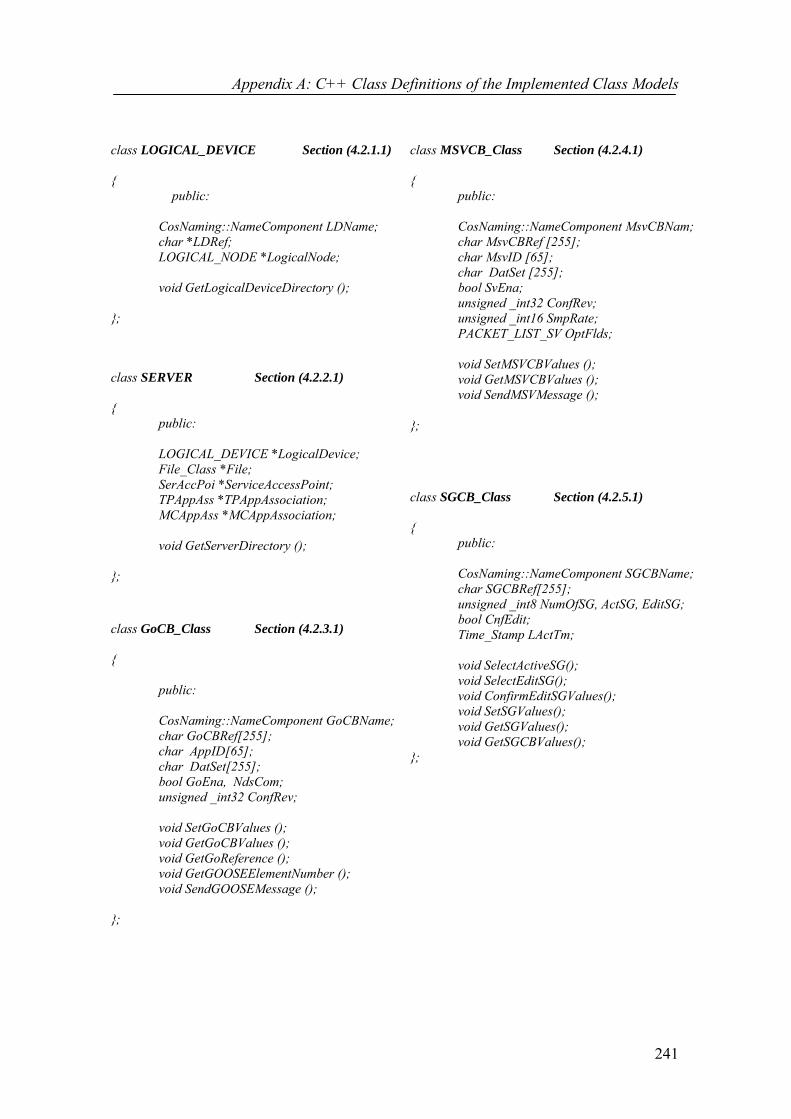
Appendix A: C++ Class Definitions of the Implemented Class Models
241
class LOGICAL_DEVICE Section (4.2.1.1) {
public:
CosNaming::NameComponent LDName; char *LDRef; LOGICAL_NODE *LogicalNode; void GetLogicalDeviceDirectory (); };
class SERVER Section (4.2.2.1) {
public:
LOGICAL_DEVICE *LogicalDevice; File_Class *File; SerAccPoi *ServiceAccessPoint; TPAppAss *TPAppAssociation; MCAppAss *MCAppAssociation;
void GetServerDirectory ();
};
class GoCB_Class Section (4.2.3.1) {
public:
CosNaming::NameComponent GoCBName; char GoCBRef[255]; char AppID[65]; char DatSet[255]; bool GoEna, NdsCom; unsigned _int32 ConfRev;
void SetGoCBValues (); void GetGoCBValues (); void GetGoReference (); void GetGOOSEElementNumber (); void SendGOOSEMessage ();
};
class MSVCB_Class Section (4.2.4.1) { public:
CosNaming::NameComponent MsvCBNam; char MsvCBRef [255];
char MsvID [65]; char DatSet [255];
bool SvEna; unsigned _int32 ConfRev; unsigned _int16 SmpRate; PACKET_LIST_SV OptFlds; void SetMSVCBValues (); void GetMSVCBValues (); void SendMSVMessage (); };
class SGCB_Class Section (4.2.5.1) {
public:
CosNaming::NameComponent SGCBName; char SGCBRef[255]; unsigned _int8 NumOfSG, ActSG, EditSG; bool CnfEdit; Time_Stamp LActTm; void SelectActiveSG(); void SelectEditSG(); void ConfirmEditSGValues(); void SetSGValues(); void GetSGValues(); void GetSGCBValues(); };

Appendix B: Descriptions of Input and Output Parameters of Services
242
Appendix B Descriptions of Input and Output Parameters of Services
The descriptions of all input and output parameters of the ACSI class services
implemented in Chapters 3 and 4 are presented in this appendix.
Table B.1 Input parameters
Parameter Name Description
ACSIClass holds the type of the selected ACSI class model {DATA, DATA-SET, BRCB, URCB, LCB, LOG, SGCB, GoCB, GsCB, MSVCB or USVCB}
ApplicationID specifies the attribute AppID, which is a visible string that represents a LD where the GoCB is located
BRCBReference is the ObjectReference of a BRCB (BRCBRef)
BufferTime specifies the attribute BufTm, which is the time interval in milliseconds for the buffering of internal notifications
DataAttributeValue [1…n] contains the value of a DataAttribute referenced by the FCDA DataReference is the ObjectReference of a DATA (DataRef)
DataSetReference is the ObjectReference of a DataSet (DSRef) DSMemRef [1…n] is an array holding the FCDA references of data and DataAttributes
Entry specifies the log entry after which the log entries should be considered
EntryIdentifier specifies the attribute EntryID, which identifies an entry in a sequence of events of a buffered report
FCDA Functionally Constraint Data Attribute (FCDA) is the reference of a specific DataAttribute of a data. It is formed by accompanying the DataAttributeRef with a value of a FC. Such as: XCBR1.Pos.ctlVal [CO]
FunctionalConstraint [0..1] contains the Functional Constraint (FC) parameter
GeneralInterrogation specifies the attribute GI, which indicates the request to start the general-interrogation process
GoCBReference is the ObjectReference of a GoCB GoEnable is the client-specified GoEna attribute, which (if set to TRUE) indicates
that the GoCB is currently enabled to send GOOSE messages
IntegrityPeriod specifies the attribute IntgPd, which indicates the period in milliseconds used for generating an integrity report
LCBReference is the ObjectReference of a LCB (LCBRef) LDReference is the ObjectReference of a LD (LDRef) LNReference is the ObjectReference of a LN (LNRef)
LogEnable is the client-specified LogEna attribute, which (if set to TRUE) indicates that the LCB is recording into the log specified by the LogRef
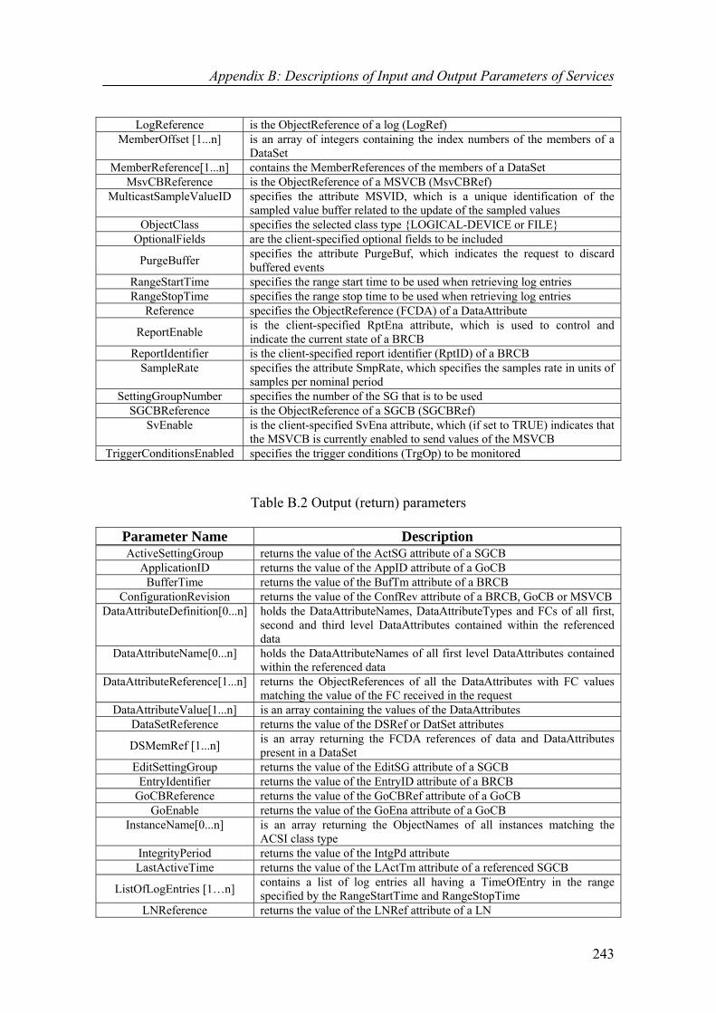
Appendix B: Descriptions of Input and Output Parameters of Services
243
LogReference is the ObjectReference of a log (LogRef) MemberOffset [1...n] is an array of integers containing the index numbers of the members of a
DataSet MemberReference[1...n] contains the MemberReferences of the members of a DataSet
MsvCBReference is the ObjectReference of a MSVCB (MsvCBRef) MulticastSampleValueID specifies the attribute MSVID, which is a unique identification of the
sampled value buffer related to the update of the sampled values ObjectClass specifies the selected class type {LOGICAL-DEVICE or FILE}
OptionalFields are the client-specified optional fields to be included
PurgeBuffer specifies the attribute PurgeBuf, which indicates the request to discard buffered events
RangeStartTime specifies the range start time to be used when retrieving log entries RangeStopTime specifies the range stop time to be used when retrieving log entries
Reference specifies the ObjectReference (FCDA) of a DataAttribute
ReportEnable is the client-specified RptEna attribute, which is used to control and indicate the current state of a BRCB
ReportIdentifier is the client-specified report identifier (RptID) of a BRCB SampleRate specifies the attribute SmpRate, which specifies the samples rate in units of
samples per nominal period SettingGroupNumber specifies the number of the SG that is to be used
SGCBReference is the ObjectReference of a SGCB (SGCBRef) SvEnable is the client-specified SvEna attribute, which (if set to TRUE) indicates that
the MSVCB is currently enabled to send values of the MSVCB TriggerConditionsEnabled specifies the trigger conditions (TrgOp) to be monitored
Table B.2 Output (return) parameters
Parameter Name Description ActiveSettingGroup returns the value of the ActSG attribute of a SGCB
ApplicationID returns the value of the AppID attribute of a GoCB BufferTime returns the value of the BufTm attribute of a BRCB
ConfigurationRevision returns the value of the ConfRev attribute of a BRCB, GoCB or MSVCB DataAttributeDefinition[0...n] holds the DataAttributeNames, DataAttributeTypes and FCs of all first,
second and third level DataAttributes contained within the referenced data
DataAttributeName[0...n] holds the DataAttributeNames of all first level DataAttributes contained within the referenced data
DataAttributeReference[1...n] returns the ObjectReferences of all the DataAttributes with FC values matching the value of the FC received in the request
DataAttributeValue[1...n] is an array containing the values of the DataAttributes DataSetReference returns the value of the DSRef or DatSet attributes
DSMemRef [1...n] is an array returning the FCDA references of data and DataAttributes present in a DataSet
EditSettingGroup returns the value of the EditSG attribute of a SGCB EntryIdentifier returns the value of the EntryID attribute of a BRCB
GoCBReference returns the value of the GoCBRef attribute of a GoCB GoEnable returns the value of the GoEna attribute of a GoCB
InstanceName[0...n] is an array returning the ObjectNames of all instances matching the ACSI class type
IntegrityPeriod returns the value of the IntgPd attribute LastActiveTime returns the value of the LActTm attribute of a referenced SGCB
ListOfLogEntries [1…n] contains a list of log entries all having a TimeOfEntry in the range specified by the RangeStartTime and RangeStopTime
LNReference returns the value of the LNRef attribute of a LN

Appendix B: Descriptions of Input and Output Parameters of Services
244
LNReference[3..n] returns the ObjectReferences of all the LNs contained within a LD LogEnable returns the value of the LogEna attribute of a log
LogReference returns the ObjectReference of a log MemberOffset[1...n] contains the MemberOffsets of the members of a DataSet for which the
MemberReferences are given MemberReference [1...n] contains the MemberReferences of the members of a DataSet for which
the MemberOffsets are given MulticastSampleValueID returns the value of the MsvID attribute of a MSVCB
NeedsCommissioning returns the value of the NdsCom attribute of a GoCB NewestEntry returns the value of the NewEntr attribute of a log
NewestEntryTime returns the value of the NewEntryTm attribute of a log NumberOfSettingGroup returns the value of the NumOfSG attribute of a SGCB
OldestEntry returns the value of the OldEntry attribute of a log OldestEntryTime returns the value of the OldEntryTm attribute of a log OptionalFields returns the value of the OptFlds attribute
Reference[0...n] returns the ObjectReferences of all LDs or FileNames of all Files within the server
ReportEnable returns the value of the RptEna attribute of a BRCB ReportIdentifier returns the value of the RptID attribute of a BRCB
Response- indicates that the service request failed Response+ indicates that the service request succeeded SampleRate returns the value of the SmpRate attribute of a MSVCB
SequenceNumber returns the value of the SqNum attribute of a BRCB SvEnable returns the value of the SvEna attribute of a MSVCB
TriggerConditionsEnabled returns the value of the OptFlds attribute of a BRCB

Appendix C: Core SNTP Classes
245
Appendix C Core SNTP Classes
The C++ definitions of the classes used to implement the core SNTP structure are
presented in this appendix. The pseudo-code description of the NTP clock filter
algorithm of Chapter 6 is also covered in this appendix along with descriptions of the
modifications made to the Ethernet Media Access Control (MAC) layer routines.
C.1 C++ Definition of the CNtpTimePacket Structure struct CNtpTimePacket
{
unsigned int_32 m_dwInteger;
unsigned int_32 m_dwFractional;
};
C.2 C++ Definition of the CNtpTime Class class CNtpTime
{
public:
// Constructors / Destructors
CNtpTime();
CNtpTime(const CNtpTime& time);

Appendix C: Core SNTP Classes
246
CNtpTime(CNtpTimePacket& packet);
CNtpTime(const SYSTEMTIME& st);
CNtpTime& operator=(const CNtpTime& time);
double operator-(const CNtpTime& time) const;
CNtpTime operator+(const double& timespan) const;
operator SYSTEMTIME() const;
operator CNtpTimePacket() const;
operator unsigned __int64() const { return m_Time; };
DWORD Seconds() const;
DWORD Fraction() const;
//Static functions
static CNtpTime GetCurrentTime();
static DWORD MsToNtpFraction(WORD wMilliSeconds);
static WORD NtpFractionToMs(DWORD dwFraction);
static double NtpFractionToSecond(DWORD dwFraction);
unsigned __int64 m_Time;
protected:
//Internal static functions and data
static DWORD m_MsToNTP[1000] ;
};
Some of the important functions of the CNtpTime Class are as follows [124]:
i. The GetCurrentTime () function returns a CNtpTime instance containing the
current Coordinated Universal Time (UTC) of the machine.
ii. The CNtpTimePacket () operator function returns a CNtpTimePacket
representation of the CNtpTime that is the actual value of the data, which gets
copied to the relevant field of the SNTP packet to be transmitted between a

Appendix C: Core SNTP Classes
247
TimeServer and a TimeClient. The function CNtpTime constructs a CNtpTime
instance from the CNtpTimePacket representation.
C.3 Pseudo-code Description of the Modified NTP Clock Filter Algorithm
Declare all the temporary variables
For (i from FMAX-1 to 1) //where FMAX is the maximum filter size
[θi-1, δ i-1, ε i-1] [θi, δ i, εi ]; // shift the set of values right
εi = εi + ϕ(T4 − T1) ; // update the dispersion of the samples
EndFor
[θ, δ, ε] [θ0, δ0, ε0 ]; // insert the new sample
For (i from0 to FMAX-1) // construct a temporary list of λ values
List [m] = εi+ | δi|/2; // add the new synchronisation distance value
For (j from0 to m-1) // sort the temporary list in the increasing λ value
If (List [j] > List [m])
List[j] List[m]; // interchange the samples
Index[j] Index[m]; // interchange the sample index numbers
EndIf
EndFor
m = m+1;
EndFor
// the supplementary code segment added
For (j from0 to FMAX-1) //search the temporary list to find the index number of the minimum λ sample
If (List [j] > List [J+1])
Index = index [j]; break;
EndIf
EndFor
// compute filter dispersion εσ
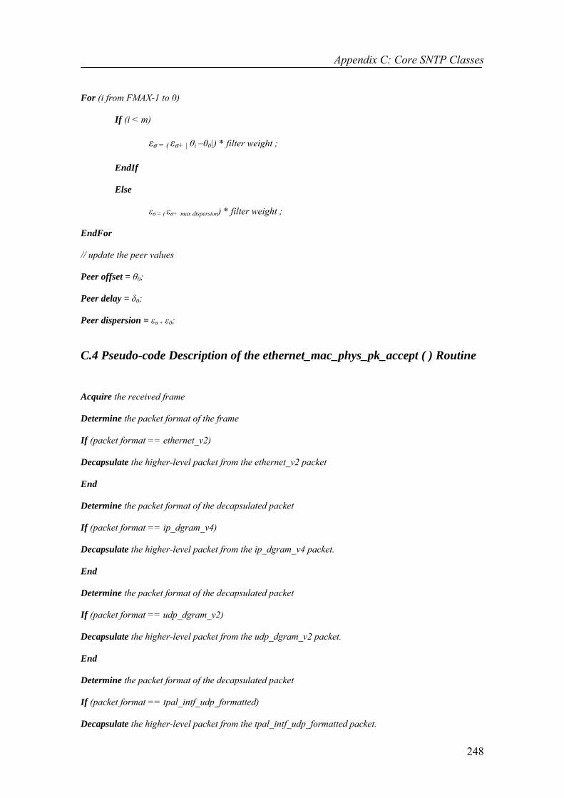
Appendix C: Core SNTP Classes
248
For (i from FMAX-1 to 0)
If (i < m)
εσ = ( εσ+ | θi –θ0|) * filter weight ;
EndIf
Else
εσ = ( εσ+ max dispersion) * filter weight ;
EndFor
// update the peer values
Peer offset = θ0;
Peer delay = δ0;
Peer dispersion = εσ + ε0;
C.4 Pseudo-code Description of the ethernet_mac_phys_pk_accept ( ) Routine Acquire the received frame
Determine the packet format of the frame
If (packet format == ethernet_v2)
Decapsulate the higher-level packet from the ethernet_v2 packet
End
Determine the packet format of the decapsulated packet
If (packet format == ip_dgram_v4)
Decapsulate the higher-level packet from the ip_dgram_v4 packet.
End
Determine the packet format of the decapsulated packet
If (packet format == udp_dgram_v2)
Decapsulate the higher-level packet from the udp_dgram_v2 packet.
End
Determine the packet format of the decapsulated packet
If (packet format == tpal_intf_udp_formatted)
Decapsulate the higher-level packet from the tpal_intf_udp_formatted packet.

Appendix C: Core SNTP Classes
249
End
Determine the packet format of the decapsulated packet
If (packet format == gna_cagil)
Decapsulate the higher-level packet from the gna_cagil packet.
End
If (packet format == SNTP)
Determine whether the Receive Timestamp (T2) field of the SNTP packet is set or not.
If (Not set)
Set the Receive Timestamp (T2) field of the SNTP packet according to the local clock.
End
Else then
Set the Destination Timestamp (T4) field of the SNTP packet according to the local clock.
End
Encapsulate the SNTP packet into the gna_cagil packet.
Encapsulate the gna_cagil packet into the tpal_intf_udp_formatted packet.
Encapsulate the tpal_intf_udp_formatted into the udp_dgram_v2 packet.
Encapsulate the udp_dgram_v2 packet into the ip_dgram_v4 packet.
Encapsulate the ip_dgram_v4 packet into the ethernet_v2 packet.
Send the ethernet_v2 packet to the higher layer.
C.5 Pseudo-code Description of the eth_mac_fdx_pks_send ( ) Routine The pseudo-code description of this routine is the same as the previous one except for
underlined code of the previous routine being replaced by the following segment:
If (packet format == SNTP)
Set the Transmit Timestamp (T3) field of the SNTP packet according to the local clock.
End
Send the ethernet_v2 packet to the physical layer.