chapter 5 applicable route and bridge type · preparatory survey on the project for construction of...
TRANSCRIPT

CHAPTER 5
APPLICABLE ROUTE AND BRIDGE TYPE

Preparatory Survey on the Project for Construction of Mykolaiv Bridge in Ukraine Final Report
5-1
5. APPLICABLE ROUTE AND BRIDGE TYPE
5.1 Review of Existing Feasibility Studies
5.1.1 Overview of the Existing Feasibility Studies Four different feasibility studies as shown below were carried out in the period running from 1989 to 2004. These feasibility studies are identified and summarised herein.
Table 5.1.1 Comparison of Basic Features in Existing Feasibility Studies
1989 F/S 2000 F/S 2003 F/S 2004 F/S Implementation
Country Soviet-Union Japan Japan Ukraine
Counterpart No information Mikolaiv City Mikolaiv City Mykolaiv Region Survey
Company Kievsoyuizdorproject Japan Consulting Institute
Pacific Consultants International Kievsoyuizdorproject
Reason for Survey
This project was identified as a key national project by the Ukrainian government.
Design Condition for Bridge was changed (aviation and navigation clearance)
The two F/S’s executed by Japan reported that the Government of Japan had expressed interest in providing a loan for this project.
Outline of Survey Result
[Road Alignment Selection] 4 routes (different crossing points on Southern Bug river) were proposed and compared. The Bridge position selected by this F/S is the same as that for the current design stage.
[Comparison of Bridge Types] Comparison of Bridge types involved 3 types. A cable-stayed bridge was recommended.
[Comparison of Bridge Types] Comparison of Bridge types involved 3 Types. A suspension bridge was recommended.
[Road Alignment Selection] Comparison of Road alignment on the left-bank was implemented. It recommended“Route 1”, which is located far from the city boundary line, as the best route. [Comparison of Bridge Types]Comparison of Bridge types involved 3 Types. A steel box-girder bridge was recommended.
Design Standard SNiP1 SNiP SNiP DBN2(and SNiP)
Source: JICA Survey Team
1 Standards for design and construction of Russia 2 Standards for design and construction of Ukraine. It was established instead of SNiP after independence from
USSR

5-2
Existing feasibility studies are as follows.
(1) Feasibility Study in 1989 developed by “Kievsoyuizdorproject”
This was implemented during the Soviet-Union era.
Four (4) options for potential bridge locations were considered: three options northwest of the city and one south of the city. This choice was documented in the “Report on Selecting a Location for the Bridge Construction across the Southern Bug River near Mykolaiv”.
The study was approved by the Head of Mykolaiv Regional Executive Committee on July 12, 1989.
It was also approved by Decree No.100-r of the Ukraine Cabinet of Ministers, dated 22 Feb.1992.
(2) Feasibility Study in 2000 generated by “Japan Consulting Institute (JCI)”
This was the first of the feasibility studies conducted in an independent Ukraine.
Development of the transport sector is essential in promoting economic reformation: all donor agencies and Ukraine as well understand that provision of aid to this sector is most important.
In 1999, the city government requested the Japan Consulting Institute to conduct a feasibility study for realization of the project.
Review of previous feasibility study and comparison of alternative bridge types over Southern Bug River were implemented.
Three options (Steel deck box girder type, cable stayed type & suspension type) were compared, with a “Cable stayed bridge” proposed after the comparison. The estimated project cost was deemed to be reasonable. A geological survey was executed on both banks of the river.
(3) Feasibility Study in 2003 generated by “Pacific Consultants International (PCI)”
The document prepared by PCI in 2003 titled "Preparation Survey on the Project of Construction of Mykolaiv Bridge in Ukraine" should be the basis for this current 2011 survey.
The Feasibility study was conducted because of changes in design conditions: aviation and navigation clearances were changed.
The navigation issue is described in article 5.1.2 and navigation dimensions and aviation limitations for each Feasibility is indicated in Table 5.1.4.
Three options (Steel truss type, cable stayed type, and suspension type) were compared, with a “Suspension bridge” recommended after the comparison.
(4) Feasibility Study in 2004 generated by “Kievsoyuzdorproect”
Mykolaiv regional state administration was the main counterpart during this study.
Three options (Steel deck box girder bridge, cable stayed bridge, and suspension bridge) were compared, with a “Steel deck box girder bridge” recommended after the comparison. DBN (Ukrainian design standard) was used for this study.

Preparatory Survey on the Project for Construction of Mykolaiv Bridge in Ukraine Final Report
5-3
5.1.2 Alignment of the bridge and approach road
1) Locations of the Bridge
Alternative alignments of the bridge were examined as in the first feasibility study in 1989. The bridge location north west and upstream of the existing Varvarovsky bridge over the Southern Bug River was recommended in this Study because it had the least effect on the social environment, i.e. minimal resettlement, and reasonable construction cost.
The proposed location of the bridge over the Southern Bug River has not been altered through the four feasibility studies.
2) Alignment of the approach road to the bridge on the left-bank
It was considered that the road alignment on the left-bank of the Southern Bug River be changed.
Background of this change is reported as follows.
The legislation regarding land ownership, land-use system, and procedures for land ownership was changed.
The city administration introduced changes to the general layout of the city by expanding residential development in the northwest direction between P-06 highway and the Southern Bug River.
It was planned that a residential community would be built to partially occupy the land previously intended to be used for left-bank approaches to the bridge.
Considering the above circumstances, this feasibility study proposed three options for the alignment on the left-bank.
Alignment 1: The alignment has one angular rotation on the horizontal curve (Radius= 3000m) where the road runs almost parallel to the city boundary and would be more than 200m away from the airport boundaries at the point of nearest approach.
Alignment 2: This alignment is considered to minimise road length. It is closer to the city boundary, and goes between the boundary and an existing cemetery. The alignment has two angular rotations with radii of 1000m.
Alignment 3: This alignment is considered to minimise land acquisition. It runs together with alignment 2 (Radius=1000m) on its west side, and then connects to the P-06 at almost a 90o angle. The alignment coincides with the existing P-06 for a section with a length of 2.2km.
The locations of the above-mentioned alignments and the old alignment (F/S in 2003) are shown in Figure 5.1.1.
The comparison of the 3 alignments on the left bank is shown in Table 5.1.2.

5-4
Source : JICA Survey Team
Figure 5.1.1 Proposed Alignments on Left-Bank
Table 5.1.2 Comparison of Proposed Alignments on the Left-Bank
Alignment 1 Alignment 2 Alignment 3 Road Length(Total) km 8.432 8.123 ○ 9.642 - new road - existing road
km km
8.432 -
8.123 -
6.540 3.102
○
Used land(Total) ha 42.8 40.9 ○ 47.7 - Agricultural - Forestry - Right of way of
existing road
ha ha ha
31.0 8.6 0.6
30.0 8.1 0.6
24.6 8.1 9.0
○
Construction Cost million Hryvnas
159.4 153.5 148.4 ○
Minimum Horizontal Curve
m R=3000 ◎ R=1000 R=1000
Connection to M23 Full Access Interchange (clover-shape)
◎ Full Access Interchange (clover-shape)
◎ Intersection at grade (T-shape*2)
Source: JICA Survey Team
This feasibility study proposed “Alignment 1” as the best of all because;
a) Alignment 1 is a continuous line which meets the requirements of “landscape design”. b) Alignment 1 does not cross security or sanitary areas of the airport or the cemetery, and
provides access to the cemetery from the city.
Alignment 1 Alignment 2
Alignment 1& 2
Alignment 3
Alignment 2 & 3
(Alignment of F/S 2003)
Asphalt plant
Forest
Cemetery

Preparatory Survey on the Project for Construction of Mykolaiv Bridge in Ukraine Final Report
5-5
c) Alignment 1 moves through more elevated locations allowing reduction in the length of overpasses required to link disconnected areas.
The following may be considered as disadvantages of “Alignment 1”;
e) It is slightly longer than “Alignment 2”. f) Relocation of Asphalt plant of Mykolaiv Regional Office will be required (Alignment 3 does
not need this).
Additional comments according to review by JICA survey team are shown below:
About a): “Alignment 1” and “2” have continuous lines, but "Road class 1st” should have more than 1200m as minimum radius of curve as specified by DBN. In light of the above, “Alignment 1” is better than “2” for road service.
About b): All alignments succeed in avoiding the cemetery. However, there is a small interchange connecting the city road to the highway. As such, “Alignment 1”is much better because it is located far from the cemetery ( no impact for cemetery land).
In consideration of the above and with due respect to the proposal of the feasibility study in 2004, “Alignment 1” was chosen as the best route for a 1st class highway.
5.1.3 Optimum Type of Main Bridge Optimum type of main bridge over the Southern Bug River recommendations;
Cable stayed bridge was recommended in the feasibility study in 2000 as a result of the comparison with steel box girder with orthotropic deck and suspension bridge type.
Suspension bridge type was recommended in the feasibility study in 2003 as a result of the comparison with steel truss bridge and cable-stayed bridge.
Steel box girder with orthotropic deck was recommended in the feasibility study in 2004 as a result of the comparison with cable stayed bridge and suspension bridge.
5.1.4 Economic and Financial Analysis Economic and financial analyses were only carried out in the feasibility studies of 2000 and 2003. The result of EIRR on the base case was 17.1% and 21.5% in 2000 and 2003 respectively. The results show that the project would be feasible.
The calculated FIRR without interest cost was 7.6% and 9.4% in 2000 and 2003 respectively. The FIRR value was judged to be low.
5.1.5 Navigation Issues The recommended optimum bridge type for the main span of the Mykolaiv Bridge is different in the feasibility studies described above. It is clearly recognized that Navigation clearance influenced the optimum bridge type strongly.
Navigation width was 120m in the feasibility study in 2000, 300m in 2003 and 2x120m in 2004; resulting in different choices for the optimum bridge type.
Therefore, careful examination is required regarding navigation issues.

5-6
5.1.6 Road Design Main Geometric parameters of the project road are shown in Table 5.1.3.
Table 5.1.3 Comparison of Road Design Conditions in Existing Feasibility Studies
1989 F/S 2000 F/S 2003 F/S 2004 F/S Category of
Road 1-a (Number of traffic lanes:4)
Length of Road 12.75km 13.19km Design Speed 150km/h
Typical width of road
3.75+(3.75*2)+6.0+(3.75*2)+3.75 Carriageway:3.75、Median:6.0m、
Shouder:3.75m(Hard shoulder:0.75m) 3.9+(3.75*2)+6.0+
(3.75*2)+3.9
Horizontal alignment road
(Left-Bank) R=2500 R=3000
Maximum vertical gradient 3.0% 2.0%
Interchange shape (Connect to P06) - - Diamond-shape Cloverleaf-shape
Interchange shape (Connect to M14) - - 3-leg Y-shape Junction
(1 point overpass) Thickness
Of pavement - 70cm 73cm
Overhead clearance of
crossing roads - 5.5m 5.0m
Source : JICA Survey Team
5.1.7 Bridge Design Design conditions for the bridge design of each Feasibility Study are summarized in Table 5.1.4.

Preparatory Survey on the Project for Construction of Mykolaiv Bridge in Ukraine Final Report
5-7
Table 5.1.4 Comparison of Bridge Design Conditions in Existing Feasibility Studies
Source: JICA Survey Team
*1--- “Construction Cost” means total of “direct cost for construction”, “assembly cost”“equipment cost” and “other indirect cost”. However, “Construction Cost” in 2004 FS shows only “direct cost for construction.”
5.2 Selection of the Highest Priority Route The current bridge location over the Southern Bug River is based on route selection of the first F/S executed by Kievsoyuizdorproekt in 1989. This section shows the review of route
2,000.0 390.0 1,610.0Steel DeckBox GirderType
130.0 25.60
2,000.0 920.0 1,080.0Cable
Stayed Br.460.0 25.60 ◎
1,996.0 1,750.0 246.0Suspension
Type1,000.0 25.60
Width(m) Heigth(m) NumberNavigation
Centerline(m)EIRR(%) FIRR(%)
Unit:Yen millon
17.09 7.61
Heigth(m)
120.0 14.5 2360 ※Reada Pilot Chart
-
Recommended
Navigation Clearance Aviation Control(m)Economic and Finacial
Analysis
Main Part of
Superstucture
Main Span(m)
Road Width(m)
ConstructionCost
2000 FS
Length ofthe Bridge
(m)
Length ofthe Main
Bridge (m)
Length ofthe Approach
Bridge (m)
2,275.0 700.0 1,575.0 Truss Type 400.0 25.60
2,275.0 760.0 1,515.0CableStayed Type
460.0 25.60
2,475.0 1,200.0 1,275.0Suspension
Type800.0 25.60 ◎
Width(m) Heigth(m) NumberNavigation
Centerline(m)EIRR(%) FIRR(%)
Unit:US$ millon
21.50 9.40
Heigth(m)
300.0 20.0 1 200 145.00
Recommended
Navigation Clearance Aviation Control(m)Economic and Finacial
Analysis
2003 FS
Length ofthe Bridge
(m)
Length ofthe Main
Bridge (m)
Length ofthe Approach
Bridge(m)
Main Part ofSuperstucture
Main Span(m)
Road Width(m)
ConstructionCost
2,007.4 883.4 1,124.0Stee l DeckBox Girder
126.0 27.44 ◎
2,015.2 824.0 1,191.2Cable
Stayed Type412.0 27.44
2,231.5 1,200.0 1,031.5Suspension
Type800.0 27.44
Width(m) Heigth(m) NumberNavigation
Centerline(m)EIRR(%) FIRR(%)
- -
Unit:UAH milon
Heigth(m)
120.0 13.5 2 500 -
Recommended
Navigation Clearance Aviation Control(m)Economic and Finacial
Analysis
2004 FS
Length ofthe Bridge
(m)
Length ofthe Main
Bridge (m)
Length ofthe Approach
Bridge(m)
Main Part ofSuperstucture
Main Span(m)
Road Width(m)
ConstructionCost

5-8
selection which considered 4 alternatives. The social environment of Mykolaiv and surrounding areas has changed in the 20 years since that F/S, which necessitated a review.
Source: JICA Survey Team (refer to F/S 2003)
Figure 5.2.1 Four Alternative Routes across Southern Bug River (F/S in 1989)
(1) Outline of 4 Routes (Starting Points described from eastern bank)
Route 1: The starting point of the route is the intersection of P-06 and M-14. The road then runs straight westwards to cross the Southern Bug River. It connects with the M-14 further westwards than other alternatives because of its straight alignment at the bridge and left-bank sections. The route would necessitate relocation of houses in the right bank area.
Route 2: The starting point of the route is the same as that for “route 1”. The road then runs in a southwest direction. It has a straight alignment and large radius curve along the boundary of Mykolaiv city before crossing the Southern Bug River. The route is the shortest among alternatives. However, the Southern Bug River has a small curve and a landslide prone area on the right bank at the bridge crossing point. The route does not necessitate house relocation.
Route 3: The route is located between “route 1”and “route 2”. House relocation required is less than that for “route 1”. Besides, the river has a gentler curve at bridge crossing point compared to “route 2”.
Route 4: The starting point of the route is the M-14 road which is located in the southeast suburb of Mykolaiv city. The route then runs straight in a western direction to cross the Southern Bug River. The route would form the southern half of a ring road for Mykolaiv city. The route would form a southern bypass compared to the northern bypass formed by the other three alternatives. The route is the longest of the 4 alternatives.
P06
M14
M14
M14
H14
Airport

Preparatory Survey on the Project for Construction of Mykolaiv Bridge in Ukraine Final Report
5-9
(2) Evaluation of Routes in F/S Stage
The result of the route evaluations is shown in Table 5.2.1.
Table 5.2.1 Comparison of 4 Alternatives at F/S stage
Good points Bad points
Route-1 L=14.6km
Shortest bridge length Better Geological condition
Approximately 100 households need to be resettled on right bank
Very close to the airport and affects radio control system
Access road length is 3.6km longer than route-2
Route -2 L=11.0km
No household or facility would need to be relocated
Shorter bridge length Total project road length including
bridge section is the shortest
Soil conditions in the river are not good
Right bank is susceptible to landslide due to steep slope
Route -3 L=12.83km
Bridge length is longer Approximately 15 households need
to be resettled on right bank. This route runs close to the silicate
wastewater treatment facility on right bank
Route -4 L=29.92km
Suitable alignment for traffic to the Rostov – Odessa direction
Total project road length including bridge section is the longest
Navigation clearance is larger due to large-scale boats, which leads to high bridge construction costs
Source: F/S 2003
According to the table above, route 2 was selected as the most suitable for the proposed road and bridge crossing because it had shorter lengths of the bridge and approach road and it hardly had any relocation of houses. The route was also aligned with future development plans for Mykolaiv city as shown in Figure 5.2.2.
(3) Significant Changes to Project Environment after F/S in 1989
Circumstances changed after Ukraine acquired independence. As regards circumstances pertinent to route selection, the environment changed as follows.
1) Drawing up of Land use plan for Mykolaiv city
Mykolaiv city drew up a land-use plan after the F/S, such that the development area for the project road was more limited than before. In fact, the location of the project road (route 2) was moved a little towards the north by the F/S in 2004. “Route 4” passes through a residential area and sports field so that its environmental impact is far more adverse than before. The land-use planning map is shown in Figure 5.2.2.

5-10
Source: JICA Survey Team
Figure 5.2.2 Four Alternatives Superimposed on Land-use Planning Map for Mykolaiv City
2) Decline of shipbuilding industry
The ship-building industry has declined compared to 20 years ago. Therefore, ship traffic volume is lower than before.
Location of SRA Regional Office

Preparatory Survey on the Project for Construction of Mykolaiv Bridge in Ukraine Final Report
5-11
3) Implementation of enhancement projects for existing roads
Road enhancement projects have been executed for some roads in Ukraine. Pertinent to the project area, an enhancement project was implemented for the existing M-14 from Mykolaiv to Kherson in 2007 under local Budget. The road sector in the area surrounding Mykolaiv is growing in importance.
4) Beginning of development plan for Ochakov port
Odessa and Ilyichevsk ports are the hub ports on the Black Sea in Ukraine now. The Ochakov port development plan started in 2008 to complement logistics capabilities on the Black Sea given that the capacity of the main ports would not be adequate in the future. The opening of Ochakov port would lead to an expansion of traffic volume through Mykolaiv.
(4) Review of Comparison of 4 Alternatives Considering Changes in Project Environment
Table 5.2.2 shows the review of comparison of alternative routes in light of the afore mentioned changes to the project environment.
Table 5.2.2 Review of Comparison of 4 Alternatives Considering Changes in Project Environment
Some circumstances pertinent to the project changed after the F/S. “Route 1”, ”Route 2” and “Route 3” remained in almost the same locations after incorporating the changes. Thus evaluation of route selection would involve comparison of the northern bypass routes (routes 1, 2 and 3) against the southern bypass route (route 4).
If attention is focused on the logistics network, the southern bypass has an advantage, because it is located far from the city centre and the route is a shortcut in the east to west directions as a corridor along the Black Sea. However, the volume of ships is increasing on the downstream side of the Southern Bug river, implying that “route 4” would require more countermeasures to deal with increased traffic of ships compared to the northern bypass routes. In addition, “route

5-12
4” has the longest approach road that would have to be newly-constructed. Therefore, “Route 4” would be more expensive and less environmentally friendly than was assumed at the F/S stage.
On the other hand, the northern bypass routes (routes 1, 2 and 3) would be implemented at lower cost than the south bypass route because of shorter approach roads and lower traffic volume of ships. Furthermore, in light of the development plan for Mykolaiv city, the northern bypass routes are more advantageous in terms of environmental impacts and land acquisition for the project. These gaps in advantages have become bigger since the F/S stage in 1989.
In terms of the wider network, the northern bypass routes are better than the southern bypass route. And according to Table.5.2.1 “Route 2” is the best route of the northern routes. The reasons are as follows.
“Route 2” requires hardly had any relocation of houses. Approach road length of “Route 2” is shortest and bridge length is shorter than route 3
and 4. “Route 1” and “Route 3” will locate on the extension of an airport runway and may
partially conflict with airspace restriction (Figure 5.3.5(b)).
5.3 Basic Design for Mykolaiv Bridge
5.3.1 Design Condition
(1) Location of the Bridge
The location of the bridge is determined to be the same as the location proposed in the F/S in 2004 (see section ‘5.2 Selection of the Highest Priority Route’ in this report). The bridge location is proposed to be approximately 9 km upstream of the existing Varvarovsky Bridge. The right bank (western side) of the crossing point is observed to be a landslide prone area with a slope of 15 degrees. On the left bank (eastern side), there is a flat area with forest, cultivated field and the Mykolaiv Air Port which is located 5 km north-northeast of the proposed bridge.

Preparatory Survey on the Project for Construction of Mykolaiv Bridge in Ukraine Final Report
5-13
Source: JICA Survey Team
Figure 5.3.1 Map Showing Location of the Proposed Bridge
(2) Road
1) General
:a) Road category 1-b
b) :Design speed 140 km/h
c) Dimensions of the road width
Location of Bridge
Aerial photo
Airport

5-14
Side walk is not installed in the cross-section of the Road.
(a) Cross-section at Road
Side walk and/or inspection way should be installed at the Main and Approach Bridges.
(b) Cross-section at Main Bridge
(c) Cross-section at Approach Bridge
Figure 5.3.2 Standard Cross-section
2) Alignment
The horizontal and vertical alignments of the bridge route were determined in section “5.2 Selection of the Highest Priority Route” of the report, with due consideration given to land use, conditions of the waterway in the river and conditions of the intersection with the road “T1506”.
■ Horizontal Alignment of the Bridge Section
R=∞ (Straight)
■ Vertical Alignment of the Bridge Section

Preparatory Survey on the Project for Construction of Mykolaiv Bridge in Ukraine Final Report
5-15
Figure 5.3.3 Horizontal and Vertical Alignments at the Mykolaiv Bridge
(3) Design standards and specifications
In principle, DBN series should be used for the design of the bridges as the design standards or specifications.
However Japanese standards such as the specifications of Honshu-Shikoku bridges and the specifications for highway bridges should be applied to the long span bridges because of its actual previous applications.
Japanese Standard and Specifications shall be used for the design and construction of SPSP foundations because it had been developed and constructed in Japan.
(4) Waterway for the Southern Bug River
1) Dimensions of the Waterway
The conditions of the waterway over the Southern Bug River are stipulated in the “DSTU 8.2.3-1-95: Navigation Clearance under Bridges on Inland Waterways (GOST26775-97)” and the class of waterway to be applied to the Southern Bug River should be “3. Trunk” according to the UKRVODSHLYAH (Ukrainian Marine and River Fleet State Enterprise on Waterways).
Table 5.3.1 Class of Waterways and Target Vessels
Depth of the navigable Channel
Estimated width/length of vessels/ships
Class Guaranteed (m)
Medium-navigation
(m)
Ship (m)
convoys of rafts (m)
Estimated height of
the vessels(m)
1.Over Trunk 3.2 3.2 36 / 220 or 29 / 280
110 / 830 or 75 / 950 15.2
2.Ditto 2.5 to 3.2 2.9 to 3.4 36 / 220 75 / 950 13.7 3.Trunk 1.9 to 2.5 2.3 to 2.9 21 / 180 75 / 680 12.8 4.Ditto 1.5 to 1.9 1.7 to 2.3 16 / 160 50 / 590 10.4 5.Local 1.1 to 1.5 1.3 to 1.7 16 / 160 50 / 590 9.6 6.Ditto 0.7 to 1.1 0.9 to 1.3 14 / 140 30 / 470 9.0 7.Ditto 0.7 0.6 to 0.9 10 / 100 20 / 300 6.6
Source: DSTU8.2.3-1-95

5-16
Table 5.3.2 Dimensions of the Waterway
Width of waterway B Class of the waterway
Height (Minimum) Fixed Bridge Bascule Bridge
1 2 (m)
3 (m)
4 (m)
1.Over Trunk 17,0 140 60 2. Ditto 15,0 140 60 3.Trunk 13,5 120 50 4.Ditto 12,0 120 40 5.Local 10,5 100/60 30 6.Ditto 9,5 60/40 - 7.Ditto 7,0 40/30 - 1) Following article should be described in the “4.9, DSTU 8.2.3-1-95”. Fixed bridges should have, as a rule, at least two courses of waterways……..etc.
Source: DSTU8.2.3-1-95
2) Centreline of the waterway
The location of the centreline for the waterway can be defined based on Figure 5.3.4 provided by State enterprise Ukrainian Water Ways “UKRVODSHLYAH.”
The distance between the centreline and the right bank is 400m which is determined with scale-up procedure on the map.

Preparatory Survey on the Project for Construction of Mykolaiv Bridge in Ukraine Final Report
5-17
Source: Ukrainian Water Ways
Figure 5.3.4 Centreline of the Waterway
3) Waterway
Navigation clearance for the Southern Bug River shall follow the regulation “DSTU 8.2.3-1-95”, and it shall be 120m in width and 13.5m high for each way. Considering the specific conditions stated below, the Survey Team confirmed the validity to have a pier between the two waterways for both directions. Ukrainian Water Ways replied to this proposal in a letter, Ref.No.2-12/350 dated 28.12.2010 (see Appendix 1). Based on the letter, the survey team adopted a single course with a 240m-waterway instead of a two-way course of 2x120m-waterways with a centre pier.
The specific conditions at the Mykolaiv Bridge site are as follows.
- Proposed bridge location is on a curved of the river where the velocity of the river stream varies depending on the position (inside or outside of the corner).
- Visibility at the bridge site is sometimes reduced by foggy weather - The centre pier between the two navigable spans is NOT preferable considering
accidental collision of vessels into the pier under the above mentioned conditions.
CentrelineRight bank
Left bank
400 m
0 200 400

5-18
The Survey Team also studied the case of a two-way course (2x120m-waterways with centre pier) for reference purposes.
(5) Restrictions for Aviation
According to a letter from International Airport Mykolaiv , Ref. No 1058 dated 24.12.2010 (see Appendix 1), they have no objection and no restriction regarding dimensions of the bridge indicated in Figure 5.3.5. However, obstruction markings on the pylons shall be required and exact location and dimensions of pylons shall be submitted to the Airport at the next design stage for their approval.
Figure 5.3.5 (a) Condition of the Proposed Bridges vis-à-vis Aviation Restrictions
* “Aircraft Approach area” does not mean restricted area for building height.
Generally, Building height is restricted in all direction at surrounding Airport.
Figure 5.3.5 (b) Condition of the Proposed Bridges vis-à-vis Aviation Restrictions
Tower
Tower
46°59’49.37”N 31°53’56.18”E Z=168m(Cable-stayed Br.) Z=103m(Suspension Br.) Based on WGS-84 system
Hor
izont
al C
lear
ance
5 k
m
AIRPORT
Aircraft Approach Area*

Preparatory Survey on the Project for Construction of Mykolaiv Bridge in Ukraine Final Report
5-19
(6) Geological Data
Geological profile at the bridge area is shown in Figure 5.3.6.
Bearing stratum of the foundation for the bridges is composed of stiff and semi-stiff lime clay as indicated in Figure 5.3.6.
Figure 5.3.6 Geological Profile
(7) Vessel Collision Force
a) Target type of vessels
It is stipulated that the length of the target type of vessel in the trunk class waterway of “DSTU 8.2.3-1-95” is 180m and the water depth of the waterway is 5m. Generally, any vessels with 180m length have more than 5m to 10m draft excluding barge type vessels. Therefore target type of vessel might be of barge type as indicated in Figure 5.3.7.
In this case, dead weight tonnages of barges are estimated at 9,000DWT.
Figure 5.3.7 Target Barge
b) Collision speed
It was hypothesized that collision of vessels with bridge piers would occur when their power unit fails to operate, when they lose control and drift. Therefore collision speed of the vessel should be the velocity of the river flow.
Observed maximum velocity of the river flow is 0.83m/s (exceedance probability=1%)
c) Vessel collision force
Collision force shall be determined using the equation below.
Source: Guide specification and commentary for vessel collision design of highway bridges, AASHTO

5-20
Target vessel 9,000 DWT Collision speed 0.83 m/s Collision force 9,500 kN
(8) Ice Load Ice load should be defined based on the following equation stipulated in the “DBN V.1.2-15:2009”.
Ψ1 Shape coefficient. =1.0 in case of rectangular structure.
Rzn Ice resistance , 735 kPa (t/m2)
b Pier width at ice impact level (m)
t Ice thickness(m) = 0.44 m based on the F/S report in 2004
Relationship between “b” and ice load “F1” is indicated in Figure 5.3.8.
橋脚(基礎)幅 と ICE LOAD
00
2,000
4,000
6,000
8,000
10,000
12,000
14,000
16,000
18,000
0 5 10 15 20 25 30 35 40 45 50
橋脚(基礎)幅 (m)
ICE L
OA
D (
kN)
Figure 5.3.8 Ice Load against Pier Width
b

Preparatory Survey on the Project for Construction of Mykolaiv Bridge in Ukraine Final Report
5-21
(9) Seismic Load
According to “DBN V.1.2-15:2009”, “DBN V.1.1-12:2006“ and “ DBN V.2.3-22:2009“, the seismic scale, i.e. MSK, at the proposed location is “6” for a 5% probability over 50 years i.e. a return period of 1000 years.
Based on the above DBN, seismic loads only need to be applied to structural designs for expected earthquake events greater than “MSK7”.
Therefore Seismic load could be neglected in this design.
Figure 5.3.9 Seismic Hazard Map
However the effect of an earthquake should be considered in the design of important bridges with long-spans, such as suspension bridges.
Based on the above DBN, the response spectrum (=K1×K2×K3×S0ki,refer to DBN V.1.1-12:2006) caused by an “MSK7” is indicated in Figure 5.3.10.
It is determined that
in the preliminary design for the suspension bridge, the effect of earthquake is estimated as horizontal force, i.e. “self-weight×0.1”.
(10) Live Load
“AK load” or “NK-cart load” should be applied as a vehicular live load in accordance with “DBN V.1.2-15-2009”.
Ski=0.0325 β
0
0.01
0.02
0.03
0.04
0.05
0.06
0.07
0.08
0.09
0 0.5 1 1.5 2 2.5
natural period (T)
β
Figure 5.3.10 Response Spectrum
MAP B 5% per 50years

5-22
AK load (Model-1)
AK load consists of “uniformly distributed load” and “tandem load” and both loads should be considered simultaneously.
:Uniformly distributed load p=0.98K=0.98×15=14.7 kN/m :Tandem load P=9.81K=9.81×15=147.15kN
Figure 5.3.11 AK Load
- Number of lanes should be determined by division of road width by 3.5m. - AK loading rules should be as follows. + Minimum distance from a center of lane to fence, barrier, parapet and curb should be
1.5m. + Minimum distance between centres of lanes should be 3.0m.
NK cart ( Model-2) load: not to be combined with seismic load
Figure 5.3.12 NK Load
NK-100: P=245 kN (Axle load)
Pedestrian live load: Uniformly distributed load
a) For a “Pedestrian bridge” and “sidewalk of a City Bridge” : q= 3.92 kN/m2 b) For sidewalks in combination with other vehicular loads: q= 1.96 kN/m2
Based on a provisional estimation, AK load effect would be approximately equal to Japanese live load.
(11) Wind Load
1) Approach Bridge
Based on the DBN, the following limit state should be considered.
1.2m 1.2m 1.2m 2.7 m
0.8 m
P/2 P/2
C=0.2m
1.5m 1.9m
0.6 m
P/2 P/2
C=0.2m p

Preparatory Survey on the Project for Construction of Mykolaiv Bridge in Ukraine Final Report
5-23
a) Limit tolerance value b) Operational value
Load intensity: Wm= γf × Wo × C
● Limit tolerance value =1.15 x 51.0 x (1.65 x 2.25 x 1.2)=261kgf/m2
● Operational value = 0.5 x 51.0 x (1.65 x 2.25 x 1.2)=114kgf/m2
where・・・ γf:: Load factor 1.15 and 0.5 at limit tolerance value and operational value respectively. Wo: wind velocity (return period is 50 years), Mykolaiv is area 3, V=29m/s,
P=500Pa(51kg/m2) C: drag coefficient and altitude modification factor
Figure 5.3.13 Zoning Map of Wind Velocity
2) Main bridge
Honshu-Shikoku bridge specification should be used instead of DBN.
Wind velocity 32m/s should be applied as a design wind speed with a return period of 100 years based on the wind speed of 29m/s for a return period of 50 years.
(12) Temperature
Highest and lowest ambient temperatures from 1876 to 2009 are 40.1 degrees and 29.7 degrees respectively. Maximum and minimum temperatures of structures are modified based on the above ambient temperatures.

5-24
Ten, five and Zero degrees are added to the highest temperature as a structural temperature in case of steel structures, composite structures and concrete structures respectively. Minimum structural temperature can be obtained from minimum ambient temperature multiplied by 0.98, 0.98 and 0.92 respectively.
Temperatures to be applied to the design is shown in Table 5.3.3.
Table 5.3.3 Structural temperature Classification
Steel bridge Steel-concrete composite bridge
Concrete bridge
Maximum temperature 50.1 45.1 40.1 Minimum temperature -29.1 -29.1 -27.3
Expected mean temperature during the construction period may be 10 degrees Celsius.
5.3.2 Location of Abutments
(1) East Side Abutment: A1
Location of abutment (A1) should be determined at the left river bank as shown in Figure 5.3.14.
Figure 5.3.14 Location of Abutment A1
6
CB52
Waterside land Spawning area Existing river bank
embankment
Protected lowland
Plan
Elevation
Bridge
Abutment:A1 PK 95+70.00

Preparatory Survey on the Project for Construction of Mykolaiv Bridge in Ukraine Final Report
5-25
There is a shallow water area with hydrophilous plants, which is 200 to 300m in length. If a banking structure is applied to the area, the length of the bridge is shortened and consequently has a lower construction cost.
However, the area should be conserved as a spawning area, territory for various creatures and area for water-purification by hydrophilous plants.
Therefore above the option is not suitable to the location for abutment A1
(2) West Side Abutment: A2
Abutment A2 should be located beyond the landslide area as shown in Figure 5.3.15.
The location of A2 was determined to have approximately a 10m margin in length from the landslide point as indicated in Figure 5.3.15.
Accordingly the bridge length was determined to be 2050m.
Figure 5.3.15 Location of Abutment A2
5.4 Main Bridge Type
5.4.1 Selection of Superstructure Type The superstructure type was determined based on the case in which the navigation channel of 240m would not be divided. For reference purposes, the case in which the navigation channel is composed of 120m (navigation width) + (pier width) + 120m (navigation width) was also investigated.
The centre span length of the main bridge should be 480m assuming that the navigation width is 240m and the pier width and construction margin are 120m. This construction margin of 120m is considered as a normal value described in Section 5.4.2.
6 0.10
2
6
껳??
꼞꼫꼶 ?
?꼦꼧꼨 껺
껳
4 115+88,3
0
9,429 CB407 CB413
Plan
Elevation Abutment A2 PK 116+20.00
River Bank
Landslide area
Estimated landslide line
Approx.10m

5-26
The alternative bridge types were proposed with reference to the span length mentioned above and the maximum span length of existing bridge types is shown in Table 5.4.1.
As can be discerned from the table, the PC-box girder bridge type is not applicable for the required span range from 290m to 360m since its limit of applicability is set at 250m. The type with hinges is not listed considering the issue of long-term creep deflection. The steel-box with orthotropic deck bridge type of the scale of 300m spans has not been constructed since 1974 due to the rise of cable stayed bridges in recent years. The truss bridge type with span limits of 400m in the continuous system was also considered as an alternative. The arch bridge type, which is normally constructed in mountainous or valley areas, is judged as inappropriate for the topographic condition of this project despite the fact that the span length is within the applicable range. The extradosed bridge type with its limit of applicability set at spans of 275m is also not applicable for the required span range. The suspension- and cable- stayed bridge types are appropriate for the long span structure and were thus lined up as alternatives.
In case the navigation channel was to be divided, the steel-box with orthotropic deck bridge type, which was proposed as the most appropriate in the feasibility study of 2004, would be selected.
Applicable bridge types shall be determined as follows:
1) Alternative 1: Suspension bridge 2) Alternative 2: Cable stayed bridge 3) Alternative 3: Steel truss bridge 4) Referential alternative: steel-box with orthotropic deck (Divided navigation channel)
Table 5.4.1 Past Record of Various Types of Bridge
World Japan
Bridge Type Bridge Name
Span (m)
Location/ Year Bridge Name Span (m)
Year
Hinge Stolmasudet 301 Norway/1998 Ejima Br. 250 2004
continuation - - - Hirahara Br. 170 1990 PC-box Girder br. Rigid
Frame - - -
Nagaragawa Viaduct
156 1999
Steel box girder br. Ponte Cost a Silva 300 Brazil/1974 Kaita Br. 250 1991
continuation Astoria Bridge 376 USA/1966 Ikitsuki Br. 400 1991 Truss br.
Gerber Quebec Bridge 549 Canada/1917 Minato Br. 510 1974
Steel Shanghai Lupu Br. 550 China/2003 Kuko Br. 380 (2011)Arch br.
concrete Wargzhou Yargtze Br 425 China/1997 Fujigawa Br. 265 2005
PC - - -
Tokunoyama Hattoku Br.
220 2006 Extradosed
Composite Japan-Palau Friendship Br.
247 Palao/2003 Kisogawa Br. 275 2002
Cable stayed br. Sutong Br. 1,088 China/2007 Tatara Br. 890 1999
Suspension br. Great belt east 1,624 Denmark/1998
Akashi Kaikyo Br.
1991 1998
5.4.2 Span Length for the Navigation Part Span length of the navigation part should be determined with consideration of the following items.

Preparatory Survey on the Project for Construction of Mykolaiv Bridge in Ukraine Final Report
5-27
- Span length shall conform to the requirements for the dimensions of the waterway after completion of the bridge.
- During construction, the requirements of the waterway should be maintained because of long term safe construction, and various risks such as vessel collision and impacts of construction accidents to 3rd parties should be eliminated.
- Area required for the construction of the tower/pylon is shown in Figure 5.4.1. - Refer to Figure 5.4.1 necessary area, i.e. length from the center of the tower to the edge
of the waterway, should be 120m.
Figure 5.4.1 Construction Plan for Foundation of Tower/Pylon
Suspension bridge:
Minimum length of the main span for the suspension bridge should be 480m considering 240m-waterway plus 120m-workspace for construction work adjacent to the waterway. In such a case, the right side anchorage will be located near the right river bank. Therefore the anchorage should be installed on the right bank for easy construction.
Waterway,should be 120m
Buoy Buoy
Tug-boat(200PS)
Anchor
30mx10m Barge
Anchor m
71m
25m Tug-boat(200PS)
Tug-boat(200PS) Buoy Buoy
30mx10m Barge Anchor
Anchor
Tug-boat(200PS)15.0m 16.0m 15.0m
7.0m 10.0m 65.0m 15.0m 7.0m 23.0m 23.0m 15.0m 65.0m 10.0m
Buoy Buoy 120.0m 120.0m
Remarks: The figure indicates arrangement of necessary facilities during construction of the foundation for the Towers.
Bargefor
material
(300t)
Barge for utility(15.0mx10.0m)
Barge for concreting
150t crawler crane(piling)
Foundation for Tower
80t crawler crane
Working gantry
Pylon Foundation

5-28
Finally main span length should be 510m because of preferable span ratio between main span(a) and side span(b), i.e. b/a= 0.2 to 0.25 should be adopted.
Preferable span ratio: b/a=0.20 to 0.25
Figure 5.4.2 Illustrative Drawing for Main Span Length
Cable stayed bridge:
Minimum required span length for main span should be 480m considering waterway width and margins identical to those for a suspension bridge.
Figure 5.4.3 Illustrative Drawing for Main Span Length
Steel truss bridge (continuous structural type):
The maximum span length in the world for a continuous steel truss bridge is 400m.
Therefore four hundred meter main-span length should be adopted to eliminate construction risks. In this case, the construction margin may be reduced from 120m to 80m.
Steel box girder with orthotropic steel deck:
This alternative will be for reference only due to the fact that it would have a pier between the 120m-waterways.
Main span of a steel box girder should be 130m considering 120m-waterway plus 10m width for the pier.
Supplemental explanation regarding the suspension bridge and the cable stayed bridge.
Large scale construction works in the river may take a long time and increase construction cost.
If the construction cost were considerably affected, the main span length would have to be revised in such a way that the tower and pylon would be placed on the right river bank. In order to clarify this matter, supplemental comparison work was carried out.
Result of the comparison works are summarized in Table 5.4.2 and Table 5.4.3.
Results clearly indicate that the alternatives with shorter spans are superior to alternatives with the longer spans.
120 240 120
480
Centerline of waterway 400
120 240 120 Centerline of waterway 400
150 155(b) 510(a)

5-29
Preparatory Survey on the Project for Construction of Mykolaiv Bridge in Ukraine Final Report
Tab
le 5
.4.2
Add
ition
al S
tabi
lity
of S
uspe
nsio
n B
ridg
e
Not
e) ◎:
Supe
rior
○:
Nor
mal △:
Infe
rior
Pla
n
Supers
tructu
re0.5
14
Subst
ruct
ure
0.4
33
A
ppro
ach B
r.0.0
53
○
T
ota
l co
st1.0
00
Supers
tructu
re:
Gir
der
, C
able
, T
ow
er
Subst
ructu
re:
Foundat
ion,
Anchora
ge
Appro
ach B
ridge
◎
Supers
tructu
re0.6
96
Subst
ruct
ure
0.5
47
△
T
ota
l co
st1.2
40
Supers
tructu
re:
Gir
der
, C
able
, T
ow
er
Subst
ructu
re:
Foundat
ion,
Anchora
ge△
Additional Study of Suspension Bridge
Sid
e V
iew
Cost
Plan A: Main Span L=510m Plan B: Main Span L=650m
Arr
angi
ng
the
Lef
t T
ow
er a
t 120m
aw
ay
from
nav
igat
ion c
han
nel
to m
ainta
insa
fety
mar
gins
for
both
const
ructi
on
and o
per
ati
on p
hase
sT
o a
rran
ge t
he
Rig
ht
Anch
ora
ge o
nla
nd n
ear
rive
r ed
ge,
then
allo
cate
the
Rig
ht
Tow
er a
t th
e posi
tion m
inim
izin
gth
e m
ain s
pan
.
Alt
ernat
ive
to P
lan A
. T
he
Posi
tion o
fth
e R
ight
Tow
er is
modifye
d b
y m
ovi
ng
it 1
40m
furt
her
inla
nd t
o im
pro
veco
nst
ruct
abili
ty.
Mai
n s
pan
lengt
h (
650m
) is
140m
lar
ger
than
that
of Pla
n A
.
Super
ior
in c
ost
aga
inst
Pla
n B
due
tonar
row
er m
ain
span
.
Infe
rior
in c
ost
agai
nst
Pla
n B
. T
o
accom
plish
the w
ider
span
, dim
ensi
on o
f
stru
ctu
ral m
em
bers
shal
l be e
nla
rged.
Appra
isal
Str
uct
ura
lF
eatu
res
Cost
(R
atio
)
Cost
(R
atio
)
: as
for
const
ant
bri
dge
lengt
h
com
pari
son w
ith P
lan B
(L
=965m
)
Str
uct
ura
lF
eatu
res
Appra
isal
PB
-0.
17CB
23
CB22
CB20
CB21
CB51
650,
000
165,
000
965,
000
120,
000
240,
000
290,
000
13,500
CB41
0CB
411
▽94
.700
▽11
0.950
▽30
.625
▽3.600
72,200
PB
-0.1
7C
B23
CB
22C
B20
CB2
1C
B51
▽79
.200
▽91.950
▽30.625
▽3.600
▽3.600
56,700
510,
000
155,
000
155,
000
820,
000
120,
000
240,
000
13,500
150,
000

5-30
Tab
le 5
.4.3
Add
ition
al S
tudy
of C
able
stay
ed B
ridg
e
Not
e) ◎:
Supe
rior
○:
Nor
mal △:
Infe
rior
Pla
n
Super
stru
cture
0.7
65
Subst
ruct
ure
0.1
46
A
ppro
ach B
r.0.0
90
○
T
ota
l co
st1.0
00
Supers
tructu
re:
Gir
der
, C
able
, T
ow
er
Subs
truct
ure
: Pie
r, F
oundat
ion
Appro
ach B
ridge
◎
Super
stru
cture
1.1
19
Subst
ruct
ure
0.1
72
△
T
ota
l co
st1.2
90
Supers
tructu
re:
Gir
der
, C
able
, T
ow
er
Subs
truct
ure
: Pie
r, F
oundat
ion
△A
ppra
isal
Str
uct
ura
lF
eatu
res
Cost
(R
atio
)
Cost
(R
atio
)
Super
ior
in c
ost
aga
inst
Pla
n B
due
tonar
row
er m
ain s
pan
.
Infe
rior
in c
ost
agai
nst
Pla
n B
. T
o
accom
plis
h t
he w
ider
span
, dim
ensi
on o
f
stru
ctu
ral m
em
bers
shal
l be e
nla
rged.
Str
uct
ura
lF
eatu
res
Appra
isal
: as
for
const
ant
bri
dge
len
gth
co
mpar
ison w
ith P
lan B
(L
=1145m
)
Additional Strudy of Cable stayed Bridge
Sid
e vi
ewD
escr
ipti
on
Plan A: Main Span L=480m Plan B: Main Span L=650m
Arr
angi
ng
both
tow
ers
at 1
20m
aw
ayfr
om
nav
igat
ion c
han
nel
to m
ainta
insa
fety
mar
gins
for
both
const
ruct
ion a
nd
oper
atio
n p
has
es
Sym
met
rica
l sp
an a
rran
gem
ent
wit
h480m
-m
ain s
pan
.
Alt
ernat
ive
to P
lan A
. T
he
posi
tion o
fth
e R
ight
Tow
er is
modifi
ed b
y m
ovi
ng
it170m
furt
her
inla
nd t
o im
pro
veco
nst
ruct
abili
ty.
Asy
mm
etri
cal sp
an a
rran
gem
ent
wit
h650m
-m
ain s
pan
.
▽3.
600
▽3.6
00
480,
000
200,
000
200,
000
880,
000
120,
000
240,
000
120,
000
PB
-0.1
7C
B23
CB
22CB
20CB
21C
B51
PB
-0.1
7CB
23
CB
22CB
20CB
21CB
51
CB41
0CB
411
▽3.6
00
650,
000
285,
000
210,
000
1,14
5,00
0
1200
0024
0,00
029
0000
13,500

Preparatory Survey on the Project for Construction of Mykolaiv Bridge in Ukraine Draft Final Report
5-31
5.4.3 Selection of Substructure Type For the substructure, the wall shaped reinforced concrete pier was basically applied.
The final shape of the pylons shall be determined in the selected bridge type based on consideration of aesthetics. The basic pylon shapes for the cable stayed- and suspension- Bridges are shown in Figure 5.4.4.
2,50
0
2,70
0
(Suspension Bridge) (Cable Stayed Bridge)
Figure 5.4.4 Basic Shapes of Pylons
5.4.4 Selection of Foundation Type
(1) Pylon Foundation Type of the Main Bridge
The following foundation alternatives were lined up considering the loading scale (center span of suspension- and cable stayed- bridges: from approx. 500m to 600m), the construction condition (Water depth of constructed area: from approx. 5m to 7m, winter concreting etc.) and the foundation condition (Depth of bearing layer: approx. 35m from river bed, Sapropel).
1) Alternative 1: Cast in place Pile Foundation 2) Alternative 2: Open Caisson Foundation 3) Alternative 3: Steel Pipe Sheet Pile Foundation (SPSP)
Table 5.4.4 shows the study results of pylon foundation type for the main bridge. Alternative 3, SPSP, was selected from among the alternatives. For the truss bridge, SPSP would also be applied since the bridge scale is almost the same and other conditions are similar. For the steel-box with orthotropic deck, SPSP would also be applied considering the investigation results of the approach bridge foundation described in Section 5.5.3.

5-32
Tab
le 5
.4.4
Com
pari
son
of P
ylon
Fou
ndat
ion
Alte
rnat
ives
(for
Sus
pens
ion
Bri
dge,
S=5
10m
)
Score
Score
Score
Outline Drawing
――
―
0.6
13
0.1
36
0.1
07
0.8
17
1.8
87
0.8
93
1.4
30
2.0
23
1.0
00
Lan
dsc
ape
Aes
thet
ics
・
△
・
○
・
△
Str
uct
ura
l
Fea
ture
s
・ ・
○
・ ・
○
・ ・△
Const
ruct
io
n
Work
abilit
y
・ ・△
・ ・△
・ ・△
Mai
nte
nan
ce・
△○
△
Envi
ronm
enta
l
Fea
ture
・
△
・
△
・
○
Appra
isal
△△
◎
Note
) ◎
:Superior
○
:norm
al
△:In
ferior
Cas
e 1
H
ypost
yle
Foundat
ion
(Cas
t in
situ P
ile D
=2.5
m)
Cost
Cas
e 2
Open C
aiss
on
Cas
e 3
Ste
el Pile S
heet
Pile
(Ste
el Pile D
=1.2
m)
Top S
lab
Item
Cost
(Rat
io)
○
Pre
cas
t fo
rmwork
can
fac
ilitat
e c
onst
ruction o
f pile
cap
on w
ater.
Expert
ise in p
ile c
onst
ruction (
excav
atio
n a
nd
stab
iliz
atio
n o
f bore
hole
) is
required.
Soft s
oil a
t riverb
ed s
hal
l be im
pro
ved for
stab
ility
of filled c
offer
dam
and for
avoid
ing o
ver-
sett
ling
of cai
sson.
Counte
rmeas
ure
agai
nst
riv
er
pollution a
re
required
due t
o v
ast
amount
of excav
atio
n.
Ste
el pile s
hould
be c
onnecte
d b
y w
eld
ing o
n
river.
Join
ts a
re lik
ely
to b
e s
tuck if bear
ing s
trat
um
is
bould
er
or
rock.
In t
hat
cas
e,
counte
rmeas
ure
s ar
e
necess
itat
ed.
Pile c
ap t
o b
e e
xpose
d a
bove w
ater
level is
lar
ge.
Rust
pro
tection for
steel cas
ing p
ipes
are r
equired
for
mai
nta
inin
g g
ood a
est
hetics.
Top s
lab t
o b
e e
xpose
d a
bove w
ater
level is
sm
all.
Rust
pro
tection is
not
necess
ary.
Ste
el sh
eet
piles
are e
xpose
d a
bove w
ater
level,
thus
rust
pro
tection is
ess
ential
to m
ainta
in g
ood
aest
hetics.
Anal
ysi
s is
bas
ed o
n e
last
ic foundat
ion o
f whic
h
length
is
sem
i-in
finite.
Due t
o t
he longer
salient
length
of pile,
non-linear
char
acte
rist
ics
should
be
consi
dere
d.
Ste
el cas
ing is
negle
cte
d fro
m C
ross
-se
ction
cal
cula
tion.
Anal
ysi
s is
bas
ed o
n e
last
ic foundat
ion o
f whic
h
length
is
finite.
Vert
ical
load
s ar
e s
upport
ed b
y
subgra
de r
eac
tion,
and h
orizo
nta
l lo
ads
are
support
ed b
y s
ubgra
de a
nd s
urr
oundin
g s
oil
reac
tions.
Cai
sson s
hould
be fill
ed w
ith c
ert
ain m
aterial
,
whic
h w
ork
s fo
r st
abiliz
atio
n o
f th
e c
aiss
on.
Anal
ysi
s is
bas
ed o
n fin
ite length
of ela
stic
foundat
ion.
Sheet
pile is
com
pose
d o
f concre
te
fille
d s
teel pile
s connecte
d b
y low r
igid
ity join
ts.
Shear
pla
tes
and s
tuds
are u
sed for
connection
betw
een s
teel piles
and t
op s
lab,
and t
ransm
it
work
ing load
s th
ere
of.
infe
rior
in c
ost
. Little a
llowan
ce for
bear
ing
resi
stan
ce o
f fo
undat
ion.
Infe
rior
in c
ost
, const
ruction w
ork
ability a
nd
environm
enta
l fe
ature
.
Superior
in s
tructu
ral fe
ature
and c
ost
.
△
Less
surp
lus
excav
atio
n m
aterial
is
pro
duced.
Riv
er
pollution is
a consi
dera
ble
ris
k d
ue t
o v
ast
amount
of excav
atio
n a
nd fill
ing o
f coffer
dam
with
mat
erial
so a
s to
sta
bilis
e it.
Environm
enta
l pro
tection m
eas
ure
s fo
r su
rplu
s
excav
ated m
aterial
and d
ischar
gin
g w
ater
are
necess
ary.
Mai
nte
nan
ce w
ork
for
aest
hetics
is n
ecess
ary.
Good in m
ainte
nan
ce w
ork
ability.
Mai
nte
nan
ce w
ork
for
aest
hetics
is n
ecess
ary.
Ste
el Piles
Tota
l C
ost
Cost
(Rat
io)
Item
Top S
lab
RC
Cai
sson
Tota
l C
ost
△
Cost
(Rat
io)
Tota
l C
ost
Cas
t in
situ P
ile
Concre
te for
Pile c
ap
Item
2,500
Bear
ing
Laye
r
2,500
Bea
ring
Laye
r
2,500
Bear
ing
Laye
r

Preparatory Survey on the Project for Construction of Mykolaiv Bridge in Ukraine Final Report
5-33
(2) Anchorage Foundation
The following foundation alternatives are lined up considering the loading scale (center span: from approx. 500m to 600m), the construction condition (Water depth of constructed area: from approx. 5m to 7m, winter concreting etc.) and the foundation condition (Depth of bearing layer: approx. 35m from river bed, Sapropel).
The investigation was carried out for the foundations within the river and on land separately.
1) Alternative 1: Open Caisson 2) Alternative 2: SPSP Foundation
The stability calculations for the anchorage foundation revealed the following.
- Open Caisson foundations with the same dimensions as SPSP foundations would not be stable.
(Calculated eccentricity of resultant force (Be=14.1m) exceeds allowable value ( Ba=8.0m)
- SPSP foundation is suitable rather than Open-caisson foundation because of presence of thick soft soil layer
Therefore the SPSP foundation should be selected for the foundation of the Anchorage.
5.4.5 Evaluation of Main Bridge Structure
(1) Evaluation Method
Evaluation of the alternatives was carried out by AHP (Analytic Hierarchy Process) method. (Refer Appendix 5: Priority Ordering Method for Bridge Type Selection)
(2) Attributes for Bride Type Selection
the following attributes were selected for bridge type evaluation by AHP
a) Construction cost b) Navigation safety c) Merit for Ukraine: environmental effects, technical transfer and use of Ukrainian
resources. d) Aesthetic features e) Construction difficulty f) Maintenance cost
(3) Scale of Relative Importance
Scale of relative importance used in the AHP is shown in Table 5.4.5.

5-34
Table 5.4.5 Scale of Relative Importance
1 A is equal to B 3 A is slightly more important or favorable than B 5 A is considerably important or favorable than B 7 A is strongly more important or favorable than B 9 A is extremely more important or favorable than B
2,4,6,8 Intermediate intensities between above numbers
(4) Weight for Attributes
Weights for attributes were determined as follows.
Table 5.4.6 Weights for Attributes
Construction cost
Navigation safety
Merit for Ukraine
Aesthetic features
Construction difficulty
Maintenance cost
Multiple mean
Construction cost 1.00 2.00 3.00 4.00 5.00 6.00 2.994
Navigation safety 0.50 1.00 2.00 3.00 4.00 5.00 1.258
Merit for Ukraine 0.33 0.50 1.00 2.00 3.00 4.00 1.258
Aesthetic features 0.25 0.33 0.50 1.00 2.00 3.00 0.792
Construction difficulty 0.20 0.25 0.33 0.50 1.00 2.00 0.505
Maintenance cost 0.17 0.20 0.25 0.33 0.50 1.00 0.335
Total 2.45 4.28 7.08 10.83 15.50 21.00 7.862 Weight 0.38 0.25 0.16 0.10 0.06 0.04 -
(5) Pair wise Matrix between bridge Type and Attribute-table
(a) Construction Cost
Estimated construction costs are tabulated in Table 5.4.7
Table 5.4.7 Construction Cost
Ratio of Cost Remarks Suspension Br. 1.075 Cable-stayed Br. 1.000 Truss Br. 1.312 Steel box girder 0.666 For reference only
Pair-wise matrix for “construction cost” based on above estimation is as follows.

Preparatory Survey on the Project for Construction of Mykolaiv Bridge in Ukraine Final Report
5-35
Table 5.4.8 Pair-wise Matrix for “Construction Cost”
Suspension Br. Cable-stayed Br. Truss Br. Steel-box Multiple meanSuspension Br. 1.00 0.50 3.00 0.20 0.740Cable-stayed Br. 2.00 1.00 4.00 0.25 1.189Truss Br. 0.33 0.25 1.00 0.14 0.328Steel box girder 5.00 4.00 7.00 1.00 3.44Total 8.33 5.75 15.00 1.59 5.697Priority 0.13 0.21 0.06 0.80 -
(b) Navigation Safety
Pair-wise matrix for “navigation safety” is as follows.
Table 5.4.9 Pair-wise Matrix for “Navigation Safety”
Suspension Br. Cable-stayed Br. Truss Br. Steel-box Multiple meanSuspension Br. 1.00 2.00 3.00 7.00 2.546Cable-stayed Br. 0.500 1.00 2.00 6.00 1.565Truss Br. 0.33 0.50 1.00 5.00 0.953Steel box girder 0.14 0.17 0.20 1.00 0.263Total 1.97 3.67 6.20 19.00 5.327Priority 0.48 0.29 0.18 0.05 -
(c) Merit for Ukraine
Pair-wise matrix for “merit for Ukraine” is as follows.
Table 5.4.10 Pair-wise Matrix for “Merit for Ukraine”
Suspension Br. Cable-stayed Br. Truss Br. Steel-box Multiple meanSuspension Br. 1.00 2.00 3.00 5.00 2.340Cable-stayed Br. 0.500 1.00 2.00 3.00 1.316Truss Br. 0.33 0.50 1.00 2.00 0.758Steel box girder 0.20 0.33 0.50 1.00 0.426Total 2.03 3.83 6.50 11.00 4.841Priority 0.48 0.27 0.16 0.09 -
(d) Aesthetic Features
Pair-wise matrix for “aesthetic features” is as follows.
Table 5.4.11 Pair-wise Matrix for “Aesthetic Features”
Suspension Br. Cable-stayed Br. Truss Br. Steel-box Multiple mean
Suspension Br. 1.00 3.00 7.00 5.00 3.201Cable-stayed Br. 0.33 1.00 5.00 3.00 1.492Truss Br. 0.14 0.20 1.00 0.33 0.310Steel box girder 0.20 0.33 3.00 1.00 0.667Total 1.67 4.53 16.00 9.33 5.670Priority 0.56 0.26 0.05 0.12 -

5-36
(e) Construction Difficulty
Pair-wise matrix for “construction difficulty” is as follows.
Table 5.4.12 Pair-wise Matrix for “Construction Difficulty”
Suspension Br. Cable-stayed Br. Truss Br. Steel-box Multiple mean
Suspension Br. 1.00 1.00 5.00 3.00 1.968Cable-stayed Br. 1.00 1.00 5.00 3.00 1.968Truss Br. 0.20 0.20 1.00 0.33 0.339Steel box girder 0.33 0.33 3.00 1.00 0.756Total 2.53 2.53 14.00 7.33 5.031Priority 0.39 0.39 0.07 0.15 -
(f) Maintenance Cost
Pair-wise matrix for “maintenance cost” is as follows.
Table 5.4.13 Pair-wise Matrix for “Maintenance Cost”
Suspension Br. Cable-stayed Br. Truss Br. Steel-box Multiple mean
Suspension Br. 1.00 1.00 2.00 0.50 1.000Cable-stayed Br. 1.00 1.00 2.00 0.50 1.000Truss Br. 0.50 0.50 1.00 0.33 0.536Steel box girder 2.00 2.00 3.00 1.00 1.861Total 4.50 4.50 8.00 2.33 4.397Priority 0.23 0.23 0.12 0.42 -
(6) Conclusions of AHP
Table 5.4.14 shows the conclusions of the “AHP”.
The alternative 1, i.e. Suspension bridge, has the highest-priority.
Table 5.4.14 Estimation of Priority
Evaluation factor Evaluated priority
Construction cost
Navigation safety
Merit for Ukraine
Aesthetic features
Construction difficulty
Maintenance cost
Weight 0.38 0.25 0.16 0.10 0.06 0.04 Priority Rank
Suspension bridge
0.13 0.48 0.48 0.56 0.39 0.23 0.34 (1)
Cable-stayed bridge
0.21 0.29 0.27 0.26 0.39 0.23 0.26 (2)
Truss bridge 0.06 0.18 0.16 0.05 0.07 0.12 0.11 (3)
Referential alternative
Steel-box bridge
0.60 0.05 0.09 0.12 0.15 0.42 0.30 -
Preparatory Survey on the Project for Construction of Mykolaiv Bridge in Ukraine Final Report
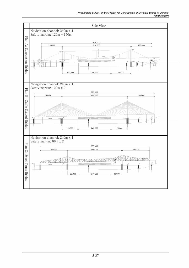
5-37
Navigation channel: 240m x 1Safety margin: 120m + 150m
Navigation channel: 240m x 1Safety margin: 120m x 2
Navigation channel: 240m x 1Safety margin: 80m x 2
Side View
Plan
A: S
usp
entio
n B
ridge
Plan
B: C
able S
tayed B
ridge
Plan
C: S
teel Tru
ss Brid
ge
PB -0.17CB23
CB22 CB20CB21 CB51
▽79.200
▽91.950
▽30.625
▽3.600 ▽3.600
56,7
00
510,000 155,000155,000820,000
120,000 240,000
13,5
00
150,000
PB -0.17CB23
CB22 CB20CB21 CB51
▽3.600 ▽3.600
480,000 200,000200,000880,000
120,000 240,000 120,000
PB -0.17CB23
CB22 CB20CB21 CB51
200,000 400,000 200,000
800,000
80,000 240,000 80,000
13,5
00

5-38
Main Br./ Superstructure (Girder, cable, tower)
Main Br./ Substructure (Foundation, anchorage) 0.293 Approach Br. (L=1540m)
Temporary bridge for construction
○
○ Main Br./ Superstructure (Girder, cable, tower)
Main Br./ Substructure (Foundation, Pier)
Approach Br. (L=1170m)
Temporary bridge for construction
○
○ Main Br./ Superstructure (main truss, lateral bracing, cross beam, etc)
Main Br./ Substructure (Foundation, Pier)
Approach Br. (L=1250m)
Temporary bridge for construction
△
△ Inferior in the aspects of construction cost, structural features, and maintenance facility.
- Main span length (400m) is determined referring to empirical & applicable span length for this
bridge type, and 80m of clearance between pier and navigation is reserved for safety margin.
- Use of high-strength steels (TH690 & HT780), which is not necessary for other plans, are
required.
- Huge gross weight of steel is required due to the magnitude of main span with 4 lane carriageway, thus
adoption of this bridge type is out of economical range.
- Although Cable erection method or Floating-crane erection method will be selected.
- Inferior in construction workability due to that the gross weight of members is larger than other plans. △
- Inferior in maintenance works due to vast number of structural member for superstructure
- Icicle on structural members over carriageway should be treated for avoiding car accidents. △
△
- Vexatious complication of members over the carriageway sometimes give oppressive feeling to
road users. △
- The design width of navigation channel can be reserved for 120m of safety margin against cramped
requirement width of 240m.
- Flat-hexagonal steel-box is adopted for improving wind-resistance stability and maintenance
workability.
- Steel pipe Sheet Pile foundation is adopted to conquest soft and deep subsoil features of riverbed.
- Cantilever erection method is suitable for construction of superstructure.
- Use of slip form for RC tower enables reduction of construction period. ○
- Periodical repaint is required for stiffening girders. ○
○
- Aesthetic design is applicable to towers of cable stayed bridge as a symbolic landmark.○
- The widest safety margin for navigation channel of all the plans.
- Flat-hexagonal steel-box is adopted for improving wind-resistance stability and maintenance
workability.
- Steel pipe Sheet Pile foundation is adopted to conquest soft and deep subsoil features of riverbed.
- Stiffening girders transported beneath the bridge by vessel are erected using lifting beam.
- Use of slip form for RC tower enables reduction of construction period. ○
- Periodical repaint is required for stiffening girders. ○
Structural
Features
Construction
Method
Maintenance
Appraisal
Maintenance
Appraisal
Landscape
Aesthetics
Construction
Prime Cost
Landscape
Aesthetics
Structural
Features
Construction
Method
Construction
Prime Cost
Structural
Features
Construction
Method
Maintenance
Appraisal
Comparison of the Plans(constant bridge length comparison inclusive of Main Bridge and Approach Bridge)
Plan
C: S
teel Tru
ss Brid
gePlan
B: C
able S
tayed B
ridge
Plan
A: S
usp
ensio
n B
ridge
Landscape
Aesthetics
Construction
Prime Cost○
- Catenary curves of main cable stretch eyesight horizontally, and create visual comfort.
- Aesthetic design is applicable to towers of cable stayed bridge as a symbolic landmark. ◎
0.348
0.3900.044 Total (Ratio):1.075 (Ratio)
(Ratio)
(Ratio)
0.5600.1070.2950.038 Total (Ratio):1.000
0.8780.0820.3160.036 Total (Ratio):1.312

Preparatory Survey on the Project for Construction of Mykolaiv Bridge in Ukraine Final Report
5-39
Navigation channel: 120m x 2Safety margin: littleR
eference : S
teel-box gird
erB
ridge
Side View
100,0005 x 130,000 = 650,000100,000
850,000
240,000
13,5
00
PB -0.17CB23
CB22 CB20 CB21 CB51
Note) ◎:Superior ○:Normal △:Inferior
Main Br./ Superstructure
Main Br./ Substructure (Foundation, Pier)
Approach Br. (L=1200m)
Temporary bridge for construction
△
△ Risk of collision with pier negates positive aspects of the bridge type.
- Intermediate pier in 240m-navigation channel is necessary due to the applicable max. span for this type of bridge.
- Risk of vessels colliding with pier in navigation channel is concerned. - Hypostyle foundation with steel piles is selected in terms of magnitude of working loads and softsubsoil features.
Procurement of Floating-crane (FC) is the key to construction (erection) of superstructure. If the FC can not be procured, construction costs would increase. △
Periodical repainting for steel girder is required. ○
◎
Ordinary bridge aspect, not to be a symbolic figure.△
Maintenance
Appraisal
LandscapeAesthetics
StructuralFeatures
ConstructionMethod
ConstructionPrime Cost
Comparison of the Plans(constant bridge length comparison inclusive of Main Bridge and Approach Bridge)
Referen
ce: Steel-
box gird
er Brid
ge
(Ratio)
0.2830.0430.3020.038 Total (Ratio):0.666

5-40

Preparatory Survey on the Project for Construction of Mykolaiv Bridge in Ukraine Final Report
5-41

5-42

Preparatory Survey on the Project for Construction of Mykolaiv Bridge in Ukraine Final Report
5-43

5-44
The construction outline of the superstructure and the SPSP
Suspension bridge
(7) Construction Method
The suspension bridge construction method is briefly described according to the major superstructure components of 1) tower works, 2) cable works and 3) stiffening girder works. The explanatory execution step diagrams are shown on the next page.
1) Tower works
- Concerning the tower execution procedure, as is shown in Step 1, it is planned to adopt the tower crane method following completion of the foundation works.
- The tower crane method involves installing a tower crane totally independent of the tower and building the tower with site-cast concrete from this.
- The concrete frame is constructed using a sliding form. - At the same time as building the tower in Step 1, a tower crane is installed and the
abutment (anchorage) cable anchor frame is installed in preparation for the cable installation works.
2) Cable works
- Concerning the cable construction method, as is shown in Step 2, following completion of the tower and installation of equipment on top of the tower, the cable preparation works are implemented.
- The cable works are broadly divided into the capable preparation works and the main cable works.
- The cable preparation works mainly comprise tacking the wire rope, installing the hauling system for drawing out the cable, and installing the catwalk, which is the scaffold for carrying out the cable placement work.
- As is shown in Step 3, the main cable execution procedure is carried out following completion of the cable preparation works.
- The main cable is installed by the air spinning (AS) method. The AS yard is located on the right bank and cables are erected going from the right bank to the left.
- The AS method, which entails spinning one cable wire at a time on-site overhead, is by far the most commonly adopted method on major suspension bridge projects overseas.
3) Stiffening girder works
- As is indicated in Steps 4 and 5, stiffening girders are directly suspended using a lifting device. Also referred to as the lifting crane method, this approach is a unique method for suspension bridges that entails using the existing main cable to place erection blocks that are carried on the river by barge.
- The assembly yard for the girder erection blocks is established near to the erection point. - Erection blocks are transported using a barge to the place directly below the suspension
point. - In areas where the barge cannot approach close to the tower, the swing method is adopted.
This entails moving the erection blocks in mid-air to the designated position through alternately suspending them from the lifting beam (the main erection machinery in the direct suspension method) and the temporary hanger rope.
- The side spans are constructed by the same method as the approach bridge.

Preparatory Survey on the Project for Construction of Mykolaiv Bridge in Ukraine Final Report
5-45
Construction of tower
Installation of facilities and saddle for the tower top

5-46
Cable stayed bridge
(8) Construction Method
The cable-stayed bridge construction method is briefly described according to the major components of 1) pylon works and 2) girder and cable works. The explanatory execution step diagrams are shown on the next page.
1) Pylon works
The construction procedure for the pylons is the same as for the towers described for suspension bridges.
- As is indicated in Step 1, following completion of the foundation works, it is planned to use the tower crane method to construct the pylons.
- The tower crane method involves installing a tower crane totally independent of the pylons and building the pylons with site-cast concrete from this.
- The concrete frame is constructed using a sliding form.
2) Girder and cable works
- Concerning the girder and cable works, the center span and side spans are constructed by the cantilever erection method starting from the pylons.
- Following completion of the pylons, as is indicated in Step 2, preparations for the girder and cable works entailing bent installation, pylon girder erection, gantry crane assembly and pylon scaffolding are carried out.
- As is indicated in Steps 3 and 4, girder erection blocks are transported using a barge and are directly suspended by gantry crane.
- The assembly yard for the girder erection blocks is established near to the erection point. - Bridge multi-cables are used. Such cables have been widely used on cable-stayed bridges
in overseas countries. - As is shown in Steps 3 and 4, the cable placement procedure entails main girder erection
→ joint installation → cable placement. - As is shown in Step 4, girder and cable installation from the pylons is closed at the
central span. - As is shown in Step 5, following closure in the central span, temporary equipment and
installations are removed.

Preparatory Survey on the Project for Construction of Mykolaiv Bridge in Ukraine Final Report
5-47
STEP-1Construction of pylon
STEP-2Installation of bent in the pylon areaErection of girder in the pylon areaAssembling of gantry craneInstallation of pylon scaffolding
STEP-3Cantilever construction of the center and side spansFormation control
STEP-4Center span closure
STEP-5Disassembly of temporary works
tower crane
sliding form
bent
main girder blockgantry crane
service crane
floor barge
installation of cables erection of girder
closure
pylon scaffolding

5-48
Truss bridge
(9) Construction Method
The construction method for truss bridges is briefly described below in reference to the step diagrams on the following page.
- As is shown in Steps 1 and 2, the intermediate supporting area (pier) is constructed by crawler crane upon installing the working gantries and bents.
- As is shown in Step 2, the center and side spans are constructed by the cantilever erection method upon installing the traveler crane on the bridge slab surface at the supporting area (pier).
- As is shown in Step 3, the truss bridge is constructed by assembling the steel members on site. These truss members are supplied from the supporting area (pier).
- Members that are supplied from the river are transported over the bridge slab surface under construction by carriage.
- As is shown in Step 4, the cantilever erection work is closed at the center span. - As is shown in Step 5, following closure at the center span, the temporary equipment and
installations are removed.
(10) Construction Issues
- Since members are assembled one at a time on-site, the construction schedule for truss bridges takes longer than for bridges that are assembled off-site.
- The large block erection method using a floating crane is also applicable but would require the procurement of a large type of floating crane and erection yard.

Preparatory Survey on the Project for Construction of Mykolaiv Bridge in Ukraine Final Report
5-49

5-50
Box girder
(11) Construction Method
The construction method for box girder bridges is briefly described below in reference to the step diagram on the following page.
- As is shown in Steps 1, 2 and 3, in view of the characteristics of this bridge type, the large block erection method using a floating crane is used to complete one span at a time.
- As is shown in Steps 3 and 4, in places inaccessible by floating crane due to the water depth, the bent erection method using the working gantry and crawler crane is applied.
- The main equipment comprises the floating crane (suspension class 1400t~2000t).
(12) Construction Issues
- It is necessary to procure a large floating crane (suspension class 1400t~2000t) during the construction period. However, large floating cranes are hard to find and suppliers are limited.
- A large assembly yard is needed to assemble a span of box girders, so temporary installation expenses are more expensive than in other bridge types.

Preparatory Survey on the Project for Construction of Mykolaiv Bridge in Ukraine Final Report
5-51
STEP-2Erection of large block ②
STEP-3Erection of large block ③~⑤Installation of working gantry and bent
STEP-4Erection of single block
STEP-5Removal of bent,working gantry
①block
②block
③block ④block ⑤block
erection of single block
setting beam
bent
working gantry
crawler crane
STEP-1Erection of large block ①

5-52
Construction outline of SPSP Foundation
Construction steps are generally as follows:
1) Driving of H-shaped guide steel from the working gantry and construction of the guide frame
2) Driving of SPSP Foundation (Vibro- )pile drive using jetting, driving pile 3) Excavation of river bed in the caisson using a pump in the water (EL-3.5m) 4) Installation of prefabricated concrete [1] preventing corrosion and mortar leakage along
the Steel Pipe Sheet pile. 5) Welding of the angle members to the joints in the water preventing mortar leakage within
the SPSP 6) Excavation and cleaning of joint pipe. Filling mortar into the joints. 7) Casting concrete inside the sheet piles by pumper truck (up to EL-3.6m) 8) Casting concrete (antiwashout under water concrete [2]) for pile caps 9) Start draining concurrently with monitoring for deformation of sheet pile 10) Connection of top slab [3]. For sheet pile, stiffening is not used. 11) Rebar arrangement for top slab and tower leg. 12) Casting concrete for top slab using pumper truck.
[1]
[2]
[4]
[3]Connection
Construction Planning for SPSP Foundation
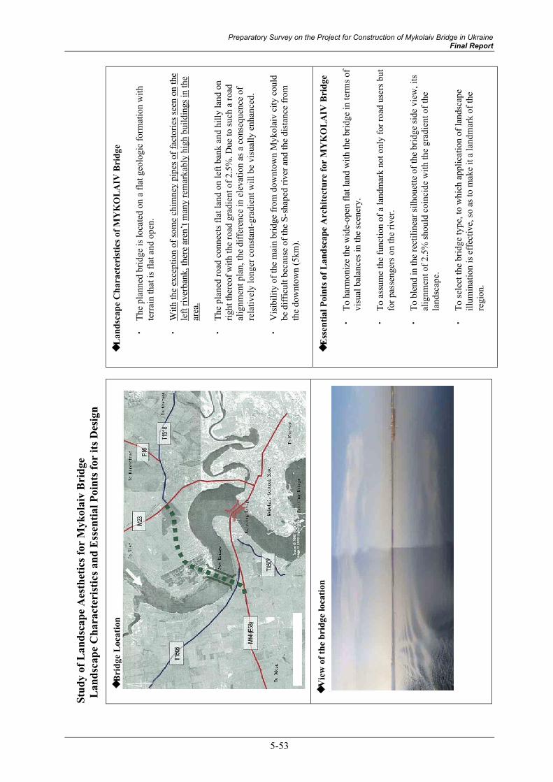
Preparatory Survey on the Project for Construction of Mykolaiv Bridge in Ukraine Final Report
5-53
◆L
ands
cape
Cha
ract
eris
tics o
f MY
KO
LAIV
Bri
dge
・
The
plan
ned
brid
ge is
loca
ted
on a
flat
geo
logi
c fo
rmat
ion
with
te
rrai
n th
at is
flat
and
ope
n.
・
With
the
exce
ptio
n of
som
e ch
imne
y pi
pes o
f fac
torie
s see
n on
the
left
river
bank
, the
re a
ren’
t man
y re
mar
kabl
y hi
gh b
uild
ings
in th
e ar
ea.
・
The
plan
ed ro
ad c
onne
cts f
lat l
and
on le
ft ba
nk a
nd h
illy
land
on
right
ther
eof w
ith th
e ro
ad g
radi
ent o
f 2.5
%. D
ue to
such
a ro
ad
alig
nmen
t pla
n, th
e di
ffer
ence
in e
leva
tion
as a
con
sequ
ence
of
rela
tivel
y lo
nger
con
stan
t-gra
dien
t will
be
visu
ally
enh
ance
d.
・
Vis
ibili
ty o
f the
mai
n br
idge
from
dow
ntow
n M
ykol
aiv
city
cou
ld
be d
iffic
ult b
ecau
se o
f the
S-s
hape
d riv
er a
nd th
e di
stan
ce fr
om
the
dow
ntow
n (5
km).
◆E
ssen
tial P
oint
s of L
ands
cape
Arc
hite
ctur
e fo
r M
YK
OLA
IV B
ridg
e
・
To h
arm
oniz
e th
e w
ide-
open
flat
land
with
the
brid
ge in
term
s of
visu
al b
alan
ces i
n th
e sc
ener
y.
・
To a
ssum
e th
e fu
nctio
n of
a la
ndm
ark
not o
nly
for r
oad
user
s but
fo
r pas
seng
ers o
n th
e riv
er.
・
To b
lend
in th
e re
ctili
near
silh
ouet
te o
f the
brid
ge si
de v
iew
, its
al
ignm
ent o
f 2.5
% sh
ould
coi
ncid
e w
ith th
e gr
adie
nt o
f the
la
ndsc
ape.
・
To se
lect
the
brid
ge ty
pe, t
o w
hich
app
licat
ion
of la
ndsc
ape
illum
inat
ion
is e
ffec
tive,
so a
s to
mak
e it
a la
ndm
ark
of th
e re
gion
.
Stud
y of
Lan
dsca
pe A
esth
etic
s for
Myk
olai
v B
ridg
e L
ands
cape
Cha
ract
eris
tics a
nd E
ssen
tial P
oint
s for
its D
esig
n
◆Br
idge
Loc
atio
n
◆V
iew
of t
he b
ridg
e lo
catio
n

5-54
◎
△
△
○
Eval
uatio
n
・
The
heig
ht o
f tow
ers a
nd to
tal s
ilhou
ette
of t
he b
ridge
are
of a
pr
efer
able
mag
nitu
de in
term
s of b
alan
ce o
f the
arti
ficia
l st
ruct
ure
agai
nst t
he fl
at a
nd o
pen
land
scap
e.
・
The
supe
rstru
ctur
e di
vide
s the
side
vie
w o
f the
tow
ers w
ith a
pr
efer
able
ratio
. Add
ition
ally
, the
out
line
of th
e br
idge
is
wra
pped
with
the
cate
nary
cur
ve o
f the
mai
n ca
ble,
whi
ch c
an
harm
oniz
e w
ith th
e re
ctili
near
silh
ouet
te o
f the
brid
ge si
de
view
.
・
As s
how
n in
the
side
vie
w il
lust
ratio
n, th
e he
ight
of t
he to
wer
s is
out
stan
ding
and
doe
s not
har
mon
ize
with
the
flat a
nd o
pen
land
scap
e. M
oreo
ver,
the
huge
tow
er (h
ill si
de) a
djac
ent t
o th
e hi
ll gi
ves a
coe
rciv
e im
pres
sion
. ・
The
stay
cab
les’
rect
iline
ar si
lhou
ette
fails
to a
ugm
ent t
he ro
ad
grad
ient
in a
ple
asan
t man
ner.
Mor
eove
r, th
e na
rrow
er sp
ace
bene
ath
the
gird
er o
f the
mai
n br
idge
spoi
ls th
e be
auty
whi
ch a
ca
ble
stay
ed b
ridge
is a
ssoc
iate
d w
ith.
・
Alth
ough
the
scal
e of
the
truss
es, s
uch
as st
ruct
ural
hei
ght,
is
adeq
uate
, thi
s pla
n gi
ves a
hea
vy im
age
due
to th
e co
mpl
icat
ed
com
pone
nts o
f the
supe
rstru
ctur
e.
・
The
truss
brid
ge is
com
pose
d of
vas
t mem
bers
, suc
h th
at it
s si
lhou
ette
giv
es a
qui
te m
assi
ve im
age.
The
rect
iline
ar ro
ad
alig
nmen
t is e
nhan
ced
acco
rdin
gly.
・
The
silh
ouet
te o
f the
brid
ge is
sim
ple
and
rect
iline
ar, s
uch
that
th
is p
lan
can
be sa
id to
be
harm
oniz
ed. H
owev
er, t
his p
lan
does
n’t h
ave
a sy
mbo
lic im
age.
・
Due
to th
e ev
enly
arr
ange
d sp
ans o
f the
mai
n br
idge
with
the
plan
e st
ruct
ure,
this
pla
n do
esn’
t hav
e vi
sual
adv
anta
ges t
o en
able
reco
gniti
on o
f the
nav
igat
ion
chan
nel f
rom
far.
Side
Vie
w o
f ove
rall
Brid
ges a
nd M
ain
Brid
ge
Bri
dge
Typ
e C
ompa
riso
n w
ith r
espe
ct to
Lan
dsca
pe A
esth
etic
s
1 2 3 ―

Preparatory Survey on the Project for Construction of Mykolaiv Bridge in Ukraine Final Report
5-55
5.5 Approach Bridge Type
5.5.1 Selection of Superstructure Type The economic and rational bridge types for middle-scale girders shown in Figure 5.5.1 are investigated for application in the span range from 30m to 60m.
The optimum span length which minimizes the total construction cost of the super- and sub-structures is estimated.
For the approach bridge, the separated structure in both directions is applied in consideration of constructability and cost.
Alternative 1 Alternative 2 Alternative 3 Alternative 4
Figure 5.5.1 Alternatives for Approach Bridge
1) Alternative 1 : Steel I-girder type with prestressed concrete slab 2) Alternative 2 : Steel box-girder type with prestressed concrete slab 3) Alternative 3 : Prestressed concrete I-girder type 4) Alternative 4 : Prestressed concrete box-girder type
5.5.2 Selection of Substructure Type As regards the substructure type of the approach bridge, the T-shaped pier, which is the most popular type for the medium scale spans, was applied.
5.5.3 Selection of Foundation Type The following foundation alternatives were lined up considering the loading scale (span: from approx. 30m to 60m), the construction condition (Water depth of constructed area: from approx. 1m to 3m, winter concreting etc.) and the foundation condition (Depth of bearing layer: approx. 35m from river bed, Sapropel).
1) Alternative 1: Cast in Place Pile Foundation 2) Alternative 2: Steel Pipe Pile Foundation 3) Alternative 3: Steel Pipe Sheet Pile Foundation (SPSP)
Table 5.5.1 shows the results of the evaluation of the optimum approach bridge foundation type. Alternative 2, the Steel Pipe Pile Foundation was selected because of followings.
- SPSP foundation type has advantage in economic efficiency rather than other foundation types.
SPSP foundation type can minimize diffusion of the settled soft soil (sapropel).

5-56
Sco
reSco
reSco
re
Outline Drawing
――
―
0.4
97
0.4
24
0.1
67
1.0
60
0.5
76
1.9
50
1.5
57
1.0
00
2.1
17
Lan
dsc
ape
Aes
thet
ics
・△
・△
・△
Str
uct
ura
lF
eatu
res
・ ・○
・ ・○
・ ・△
Const
ruct
ion
Work
abili
ty
・ ・△
・ ・○
・ ・△
Mai
nte
nan
ce・
△・
△・
△
Envi
ronm
enta
lFea
ture
・△
・○
・○
Appra
isal
○◎
△
Note
) ◎
:Super
ior
○
:norm
al
△:In
ferior
Cas
e 1
Hyp
ost
yle
Foundat
ion
(Cas
t in
situ P
ile D
=1.2
m)
Cost
Cas
e 2
Hyp
ost
yle
Foundat
ion
(Ste
el P
ipe
Pile
D=1.0
m)
Cas
e 3 S
teel
Pile
Shee
t Pile
(Ste
el P
ile D
=1.2
m)
Top
Sla
bIt
emC
ost
(Rat
io)
△
Pre
cast
form
work
can
fac
ile c
onst
ruct
ion o
fpile
cap
on w
ater
.E
xper
tise
know
ledge
for
pile
const
ruct
ion
(exc
avat
ion
and s
tabi
lizat
ion
of b
ore
hole
) ar
ere
quired
.
Pre
cast
form
work
can
fac
ile c
onst
ruct
ion o
fpile
cap
on w
ater
.Pile
is
drive
n b
y vi
bro
-ham
mer
and/or
dro
p-
ham
mer
fro
m v
esse
l. D
rivi
ng
pro
cedure
is
sim
ple
, an
d c
onst
ruct
ion p
erio
d is
short
erth
an o
ther
s.
Ste
el p
ile s
hould
be
connec
ted b
y wel
din
g on
rive
r.Jo
ints
are
lik
ely
to b
e st
uck
if bea
ring
stra
tum
is b
ould
er o
r ro
ck.
In t
hat
cas
e,co
unte
rmea
sure
s ar
e nec
essi
tate
d.
Pile
cap
to b
e ex
pose
d a
bove
wat
er lev
el is
larg
e. R
ust
pro
tect
ion for
stee
l ca
sing
pip
esar
e re
quired
for
mai
nta
inin
g a
good
Pile
cap
to b
e ex
pose
d a
bove
wat
er lev
el is
larg
e. R
ust
pro
tect
ion for
stee
l pip
es a
rere
quired
for
mai
nta
inin
g a
good
aes
thet
ics.
Ste
el s
hee
t pile
s ar
e ex
pose
d a
bove
wat
erle
vel, t
hus
rust
pro
tect
ion is
required
for
mai
nta
inin
g a
good
aes
thet
ics.
Anal
ysis
is
bas
ing
on e
last
ic foundat
ion o
fw
hic
h len
gth is
sem
i-in
finite.
Due
to t
he
longe
r sa
lient
lengt
h o
f pile
, non-lin
ear
char
acte
rist
ics
should
be
consi
der
ed.
Ste
el c
asin
g is
neg
lect
ed fro
m C
ross
-se
ctio
nca
lcula
tion.
Anal
ysis
is
bas
ing
on e
last
ic foundat
ion o
fw
hic
h len
gth is
sem
i-in
finite.
Due
to t
he
longe
r sa
lient
lengt
h o
f pile
, non-lin
ear
char
acte
rist
ics
should
be
consi
der
ed.
Corr
osi
on t
hic
knes
s of st
eel pip
e is
consi
der
ed for
Cro
ss-se
ctio
n c
alcu
lation.
Anal
ysis
is
bas
ing
on fin
ite
lengt
h o
f el
astic
foundat
ion.
Shee
t pile
is
com
pose
d w
ith
conc
rete
fill
ed s
teel
pile
s co
nnec
ted
by
low
rigi
dity
join
ts.
Shea
r pla
tes
and s
tuds
are
use
d for
connec
tion b
etwee
n s
teel
pile
s an
d t
op s
lab,
and t
ransm
it w
ork
ing
load
s th
ereo
f.
Eco
nom
ical
and g
ood s
truct
ura
l fe
ature
.M
ost
eco
nom
ical
& g
ood s
truct
ura
l fe
ature
.in
ferior
in c
ost
and c
onst
ruct
ion w
ork
abili
ty.
△
Few
surp
lus
soil
is m
ade.
Good for
envi
ronm
ent
(little
const
ruct
ion
was
te (
exca
vate
d s
oil
& b
ento
nite
wat
er).
Envi
ronm
enta
l m
easu
res
for
surp
lus
soil
and
dis
char
ging
wat
er is
nec
essa
ry.
Mai
nte
nan
ce w
ork
for
aest
het
ics
is n
eces
sary
.M
ainte
nan
ce w
ork
for
aes
thet
ics
is n
eces
sary
.M
aint
enan
ce w
ork for
aest
hetics
is
nece
ssar
y.
Stee
l Pile
sT
otal
Cost
Cost
(Rat
io)
Item
Con
cret
e fo
r Pile
Ste
el P
ileT
ota
l C
ost
○
Cost
(R
atio
)
Tota
l C
ost
Cas
t in
situ P
ileC
oncr
ete
for
Pile
Item
Bea
ring
Laye
rB
earin
g La
yer
22,5
00
7,5002,500 32,000
23,5
00
8,5002,500
Bea
ring
Laye
r
32,000
9,00
0
2,500 32,000
Tab
le 5
.5.1
Com
pari
son
for
App
roac
h B
ridg
e Fo
unda
tion
(for
Ste
el G
irde
r B
ridg
e, S
=45m
)

Preparatory Survey on the Project for Construction of Mykolaiv Bridge in Ukraine Final Report
5-57
5.5.4 Comparison Table for Approach Bridge
(1) Evaluation Method
Evaluation of the alternatives was carried out by AHP (Analytic Hierarchy Process) method, i.e. Priority Ordering Method for Decision Making.
Attributes and weights used in AHP are same as those in article 5.4.5.
(Refer to article 5.4.5)
(2) Pair Wise matrix between Bridge type and Attribute Table
(a) Construction Cost
Estimated construction costs are tabulated in Table 5.5.2.
Table 5.5.2 Construction Cost
Type of bridge Ratio of Cost Remarks Alternative-1 Steel I-girder bridge 1.000 Alternative-2 Steel box-girder bridge 1.303 Alternative-3 PC-I girder 1.018 Alternative-4 PC-box-girder 1.272
Pair-wise matrix for “construction cost” based on above estimation is as follows.
Table 5.5.3 Pair-wise Matrix for “Construction Cost”
Steel I-girder Steel box-girder PC I-girder PC box-girder Multiple mean Steel I-girder 1.00 7.00 2.00 5.00 2.030 Steel box-girder 0.14 1.00 0.50 1.00 0.644 PC-I girder 0.50 2.00 1.00 2.00 1.122 PC-box-girder 0.20 1.00 0.50 1.00 0.681 Total 1.84 11.0 4.00 9.00 4.478 Priority 0.45 0.14 0.25 0.15 -
(b) Navigation Safety
Pair-wise matrix for “navigation safety” is as follows.
Table 5.5.4 Pair-wise Matrix for “Navigation Safety”
Steel I-girder Steel box-girder PC I-girder PC box-girder Multiple meanSteel I-girder 1.00 1.00 1.00 1.00 1.00 Steel box-girder 1.00 1.00 1.00 1.00 1.00 PC-I girder 1.00 1.00 1.00 1.00 1.00 PC-box-girder 1.00 1.00 1.00 1.00 1.00 Total 4.00 4.00 4.00 4.00 4.00 Priority 0.25 0.25 0.25 0.25 -

5-58
(c) Merit for Ukraine
Pair-wise matrix for “merit for Ukraine” is as follows.
Table 5.5.5 Pair-wise Matrix for “Merit for Ukraine”
Steel I-girder Steel box-girder PC I-girder PC box-girder
Multiple mean
Steel I-girder 1.00 1.00 2.00 1.00 1.122 Steel box-girder 1.00 1.00 2.00 1.00 1.122 PC-I girder 0.50 0.50 1.00 0.33 0.661 PC-box-girder 1.00 1.00 3.00 1.00 1.201 Total 3.50 3.50 8.00 3.33 4.107 Priority 0.27 0.27 0.16 0.29 -
(d) Aesthetic Features
Pair-wise matrix for “aesthetic features” is as follows.
Table 5.5.6 Pair-wise Matrix for “Aesthetic Features”
Steel I-girder Steel box-girder PC I-girder PC box-girder
Multiple mean
Steel I-girder 1.00 1.00 3.00 1.00 1.201 Steel box-girder 1.00 1.00 3.00 1.00 1.201 PC-I girder 0.33 0.33 1.00 0.33 0.577 PC-box-girder 1.00 1.00 3.00 1.00 1.201 Total 3.33 3.33 10.00 3.33 4.180 Priority 0.29 0.29 0.14 0.29 -
(e) Construction Difficulty
Pair-wise matrix for “construction difficulty” is as follows.
Table 5.5.7 Pair-wise Matrix for “Construction Difficulty”
Steel I-girder Steel box-girder PC I-girder PC box-girder
Multiple mean
Steel I-girder 1.00 1.00 5.00 7.00 1.809 Steel box-girder 1.00 1.00 5.00 7.00 1.809 PC-I girder 0.20 0.20 1.00 0.33 0.487 PC-box-girder 0.14 0.14 3.00 1.00 0.628 Total 2.34 2.34 14.00 15.33 4.732 Priority 0.38 0.38 0.10 0.13 -

Preparatory Survey on the Project for Construction of Mykolaiv Bridge in Ukraine Final Report
5-59
(f) Maintenance Cost
Pair-wise matrix for “maintenance cost” is as follows.
Table 5.5.8 Pair-wise Matrix for “Maintenance Cost”
Steel I-girder Steel box-girder PC I-girder PC box-girder
Multiple mean
Steel I-girder 1.00 1.00 0.20 0.20 0.585 Steel box-girder 1.00 1.00 0.20 0.20 0.585 PC-I girder 5.00 5.00 1.00 1.00 1.710 PC-box-girder 5.00 5.00 1.00 1.00 1.710 Total 12.00 12.00 2.40 2.40 4.590 Priority 0.13 0.13 0.37 0.37 -
(3) Conclusions of AHP
Table 5.5.9 shows the conclusions of the “AHP”.
Alternative 1, i.e. Steel I-girder, has highest-priority.
Table 5.5.9 Estimation of Priority
Evaluation factor Evaluated priority
Construction cost
Navigation safety
Merit for Ukraine
Aesthetic features
Construction difficulty
Maintenance cost
Weight 0.38 0.25 0.16 0.10 0.06 0.04 Priority Ran
k
Steel I-girder 0.45 0.25 0.27 0.29 0.38 0.13 0.338 (1)Steel box-girder 0.14 0.25 0.27 0.29 0.38 0.13 0.220 PC-I girder 0.25 0.25 0.16 0.14 0.10 0.37 0.220 PC-box- girder 0.15 0.25 0.29 0.29 0.13 0.37 0.221 -

5-60
Steel I
00
2,000
4,000
6,000
8,000
10,000
12,000
14,000
25 30 35 40 45 50 55 60 65
SPAN (m)
Const
ruction C
ost
(/m
)
Total
Superstructure
Foundation
Steel Box
00
2,000
4,000
6,000
8,000
10,000
12,000
14,000
25 30 35 40 45 50 55 60 65
SPAN (m)
Const
ruction C
ost
(/m
)
Total
Superstructure
Foundation
PC Composit
00
2,000
4,000
6,000
8,000
10,000
12,000
14,000
25 30 35 40 45 50 55 60 65
SPAN (m)
Const
ruction C
ost
(/m
)
Total
Superstructur
Foundation
PC BOX
00
2,000
4,000
6,000
8,000
10,000
12,000
14,000
25 30 35 40 45 50 55 60 65
SPAN (m)
Cost
rruction C
ost
(/m
)
Total
Superstructure
Foundation
支点部 径間部
2700 9500 5000
29400
2.5%1.5%
9500 2700
支点部 径間部
2700 9500 5000
29400
2.5%1.5%
9500 2700
2700 9500 5000
29400
2.5%1.5%
9500 2700
支点部 径間部
Table 5.5.10 Comparison for Span Length Types Cross Section Economical Span Cost
SPAN=45m
Cost (Ratio) Superst.: 0.635 Subst. : 0.365 Total : 1.000
I-section girder
Appraisal: ◎
SPAN=45m
Cost Superst.: 0.938 Subst. : 0.365 Total : 1.303
Steel box girder
△Appraisal:
SPAN=40m
Cost Superst.: 0.607 Subst. : 0.411 Total : 1.018
PC composite
girder
Appraisal: ○
SPAN=45m
Cost Superst.: 0.894 Subst. : 0.377 Total : 1.272
PC-box Girder
△Appraisal:
2700 9500 5000
29400
2.5%1.5%
9500 2700
支点部 径間部
Note) ◎:Superior ○:Normal △:Inferior
Support Section Middle Section
Support Section Middle Section
Support Section Middle Section
Support Section Middle Section

Preparatory Survey on the Project for Construction of Mykolaiv Bridge in Ukraine Final Report
5-61
Construction outline of steel bridge
(1) Construction Method
The bent erection method using a crawler crane from the working gantries (used for the substructure).
Main equipment
Crawler crane, working gantries, bent, etc.
(2) Construction Issues
The construction schedule is expected to be long due to the erection of members singly.
The large block erection method by the span is also applicable, however, it requires an erection yard.
crawler crane
working gantrybent
Installation direction
5.6 Preliminary Design of the Bridge
5.6.1 Selection of Superstructure Type
(1) Superstructure Type for Main Span
As a result of the quantitative evaluation for cost, structure, construction, etc. the suspension bridge appeared to be the most appropriate type in which the navigation safety during construction and the aesthetic satisfaction are highly ensured.
Among the alternatives, the suspension bridge type also cleared economic issues and required no pier to be provided in the navigation channel, which would be detrimental due to the navigational conditions (curved channel and dense fog). The referential alternative D of steel-box with orthotropic deck providing a pier in the navigation channel was economical; it was however, disadvantageous in other aspects.

5-62
*Suspension Bridge with single span stiffened-girder or 3-span stiffened-girder
Suspension bridge with single span stiffened-girder is supposed in course of selection procedure for bridge type. Suspension bridge with three (3)-span stiffened-girder can be proposed in lieu of single span type. The reason not to propose above is as follows.
- The selected type of the approach bridge, i.e., steel I-girder type with prestressed concrete slab, must be more economical rather than side span of suspension bridge with orthotropic box girder.
- Because main cables are positioned under stiffen girder height at side span of the right bank side, hanger cables can not be installed.
- If main cables move to above deck level, lager anchorage should be required and it cause to additional cost.
(2) Superstructure Type for approach portion
As a result of the quantitative evaluation for cost, structure, construction, etc. the steel I-girder type with prestressed concrete slab appeared to be the most appropriate one from an economic perspective.
5.6.2 Selection of Substructure Type
(1) Substructure and Foundation for the Main Bridge Tower is generally made of reinforced concrete in no seismic area and steel structure in seismic area. The towers of suspension bridge are made of reinforced concrete because of weak seismic design force.
Foundation type, Steel Pile Sheet Pile (SPSP), for Anchorage and Tower is advantageous in economic and environmental aspect. Regarding environmental issue, SPSP can minimize diffusion of the settled soft soil (sapropel).
(2) Substructure and Foundation for the Approach Bridge Pier has separated columns made of reinforced concrete for each direction but its pile cap is unified due to required arrangement of piles.
Steel Pipe Pile Foundation is superior to other type of foundations in respect to cost efficiency and environment aspect.
Multi-column foundation which pile cap is located above water surface is adopted because of non-requirement of cofferdam and excavation of soft soil layer (Sapropel) during construction period.
Multi-column foundation would be obstacle against to river flow.
However influence to river flow should be limited because of sufficient width of river at proposed location compare to narrow section at downstream.
5.6.3 Preliminary Design of the Bridge Preliminary design of the bridge is carried out based on the selected type of the following structures.

Preparatory Survey on the Project for Construction of Mykolaiv Bridge in Ukraine Final Report
5-63
Main Bridge
Superstructure: Suspension Bridge with single span stiffened-girder
Tower : Rigid Frame made of reinforced concrete with portal shape
Foundation of Anchorage and Tower: Steel Pipe Sheet Pile
Approach Bridge
Superstructure: Steel I-Girder with Prestressed Concrete Slab
Type of Pier: Twin Column/wall type
Foundation: Steel Pipe Pile, Multi-Column Type
Results of the preliminary design are compiled in “Volume 2: Preliminary Design Drawings.”
In the Volume 2, Design conditions, Results of the structural analysis and design calculations, Dimension of the structures and Maintenance plan are indicated together with drawings.
Especially, the dehumidification system that is state-of-the-art technology is recommended to prevent deterioration of the main cable system.

5-64

Preparatory Survey on the Project for Construction of Mykolaiv Bridge in Ukraine Final Report
5-65

5-66

Preparatory Survey on the Project for Construction of Mykolaiv Bridge in Ukraine Final Report
5-67

5-68
5.7 Preliminary Design for Approach Road
5.7.1 Location of the Road
(1) Confirmation of Road Alignment
Alignment selection of the M-14 bypass road was implemented in the F/S in 2004, and it was reviewed by the JICA survey team (refer to ‘5.1.2 Alignment of the Bridge’ in this report). Here confirmation is shown for the road alignment as a “1-b class road”, after the topographic survey, DBN study and investigation of site condition.
1) Aspect of Alignment
Road class “1-b” is for a 140 km/h design speed. Horizontal alignment of M-14 bypass has 3 radiuses more than R=3000m and 1 radius (R=1200m), they are in compliance with DBN. A super elevated section (R=1200m) is on the right bank of the Southern Bug River, but this section has a shallow longitudinal gradient (0.5%). The crossing point of the Southern Bug River and P-06 highway, alignment is “straight” that is better for road users and better for longitudinal design, structural design and construction planning. The connection point with P-06 highway is a clover leaf junction; this is fitted road to users because it is a general style in Ukraine.
The above alignment factors satisfy the requirements for road service level as a “1-b”class road.
2) Number of Lanes
According to DBN V 2.3-4-2007, number of lanes is determined by traffic demand forecast, and target year is 20 years after motor road construction is completed.
Table 5.7.1 Traffic Volume and Number of Lanes
Terrain relief Traffic volume (PCU/day) Number of lanesFrom more than 14000 to 40000 4 From more than 40000 to 80000 6
Plane and undulated
More than 80000 8
More than 10000 to 34000 4 More than 34000 to 70000 6
Mountain
More than 70000 8
Source: DBN V.2.3-4 -2007
Traffic volume on Mykolaiv Bridge will be 37600 PCU/day in 2035, and 42900PCU/day in 2040(refer to Table 4.2.21 “Future Traffic Volume at New Mykolaiv Bridge”). From them, the prospect traffic volume in target year (2038) is 40000 PCU/day approximately. This future traffic volume is considered Ochakov port development (100% completed) and toll free Mykolaiv Bridge. Thus considering number of traffic lane, “4 lanes” is fit.
3) Impact on Land and Land users
The area of connection with P-06 will be constructed as a clover leaf junction, and land acquisition should be done over a wide area. There is an asphalt plant but it belongs to Mykolaiv government and it had already stopped operation.
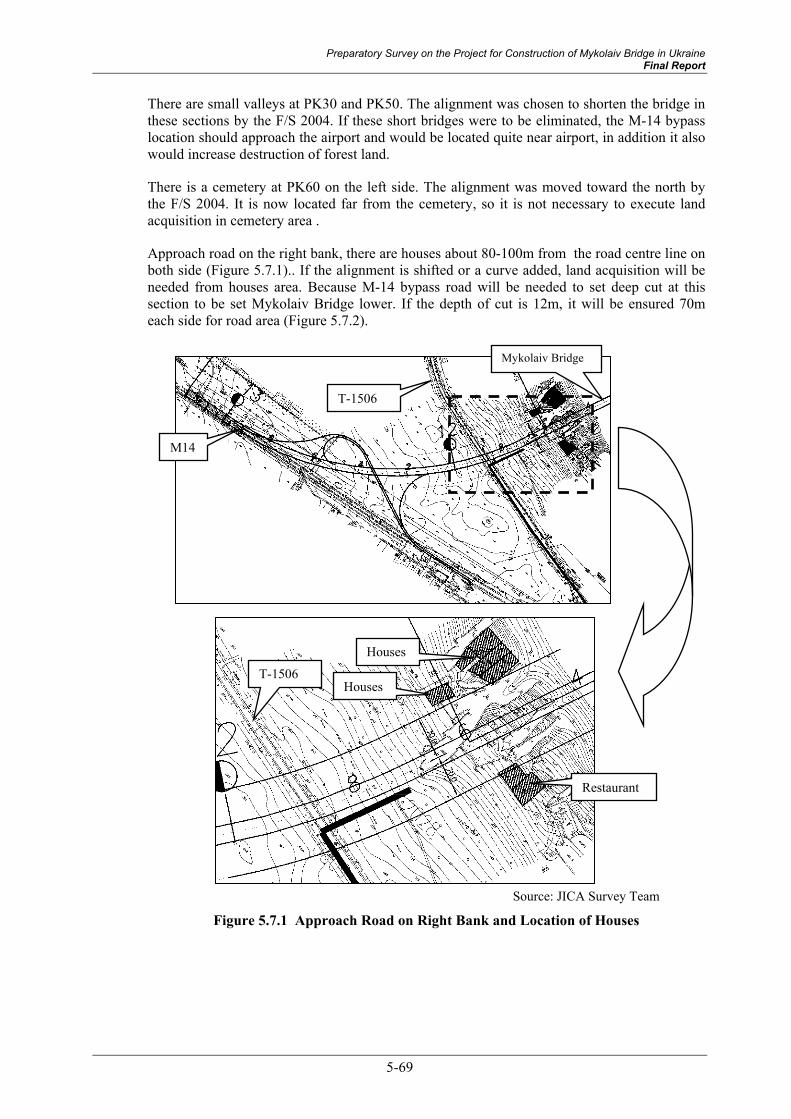
Preparatory Survey on the Project for Construction of Mykolaiv Bridge in Ukraine Final Report
5-69
There are small valleys at PK30 and PK50. The alignment was chosen to shorten the bridge in these sections by the F/S 2004. If these short bridges were to be eliminated, the M-14 bypass location should approach the airport and would be located quite near airport, in addition it also would increase destruction of forest land.
There is a cemetery at PK60 on the left side. The alignment was moved toward the north by the F/S 2004. It is now located far from the cemetery, so it is not necessary to execute land acquisition in cemetery area .
Approach road on the right bank, there are houses about 80-100m from the road centre line on both side (Figure 5.7.1).. If the alignment is shifted or a curve added, land acquisition will be needed from houses area. Because M-14 bypass road will be needed to set deep cut at this section to be set Mykolaiv Bridge lower. If the depth of cut is 12m, it will be ensured 70m each side for road area (Figure 5.7.2).
Source: JICA Survey Team
Figure 5.7.1 Approach Road on Right Bank and Location of Houses
M14
Mykolaiv Bridge
T-1506
Houses
Restaurant
Houses T-1506

5-70
Source: JICA Survey Team
Figure 5.7.2 Road Area of Each Side (Case: Cut depth 12m)
With the above considerations the alignment fits the updated conditions; therefore it is not necessary to change the alignment.
4) Longitudinal Alignment
The longitudinal alignment was reset in the preliminary design because of site conditions updated by the topographic survey. It is shown in “Appendix 4” and “Volume.2: Preliminary Design Drawings”.
(2) Location of the Road
The location of the road is determined to be the same location as proposed “Alignment 1” in the F/S in 2004 (refer to 5.1.2 Alignment of the Bridge’ in this report).

Preparatory Survey on the Project for Construction of Mykolaiv Bridge in Ukraine Final Report
5-71
Source: JICA Survey Team
Figure 5.7.3 Location of the road (M-14 Bypass Road)
5.7.2 Constitution of the M-14 Bypass Road Construction Project The M-14 bypass road consists of 3 sections; the approach road on the left bank, the bridge section and the approach road on the right bank. Furthermore, it has 2 junctions to connect the existing trunk roads (M-14, P-06) and relocation of P-06. Their project scale is shown in Table 5.7.2.

5-72
Table 5.7.2 Constitution of M-14 Bypass Road Project
Road Scale of Road Outline Approach Road (Left bank) 9.57km
(4 lanes) PK 0-PK95+70
-Earthwork section -Fill section: 8.4km -Cut section:1.2km -5 small bridges and 1 small bridge for railway -3 minor intersections
Bridge Section (Southern Bug River)
2.05km (4 lanes) PK95+70-PK116+20
-Suspension bridge :0.81km -Approach bridge:1.24km
Approach Road (Right bank) 1.57km (4 lanes) PK116+20-PK131+92.99
-Earthwork section -Fill section: 0.5km -Cut section:1.1km -1 middle bridge for crossway
M-14 Bypass
Total 13.19km (4 lanes)
North Junction (M14 bypass and P-06)
8 Ramp-ways Clover-leaf shape
Earthwork section Junction
South Junction (M14 bypass and M-14)
3 Ramp-ways 3-leg Y-shape
Earthwork section -1 small bridge for ramp-way
P-06 Relocation 1.3km (4 lanes)
Earthwork section -1 middle bridge
Source: JICA Survey Team

Preparatory Survey on the Project for Construction of Mykolaiv Bridge in Ukraine Final Report
5-73
Figu
re 5
.7.4
Typ
ical
Cro
ss se
ctio
n (1
)

5-74
Figu
re 5
.7.5
Typ
ical
Cro
ss se
ctio
n (2
)

Preparatory Survey on the Project for Construction of Mykolaiv Bridge in Ukraine Final Report
5-75
Figu
re 5
.7.6
Pla
n of
M-1
4 B
ypas
s Roa
d (1
)

5-76
Figu
re 5
.7.7
Pla
n of
M-1
4 B
ypas
s Roa
d (2
)
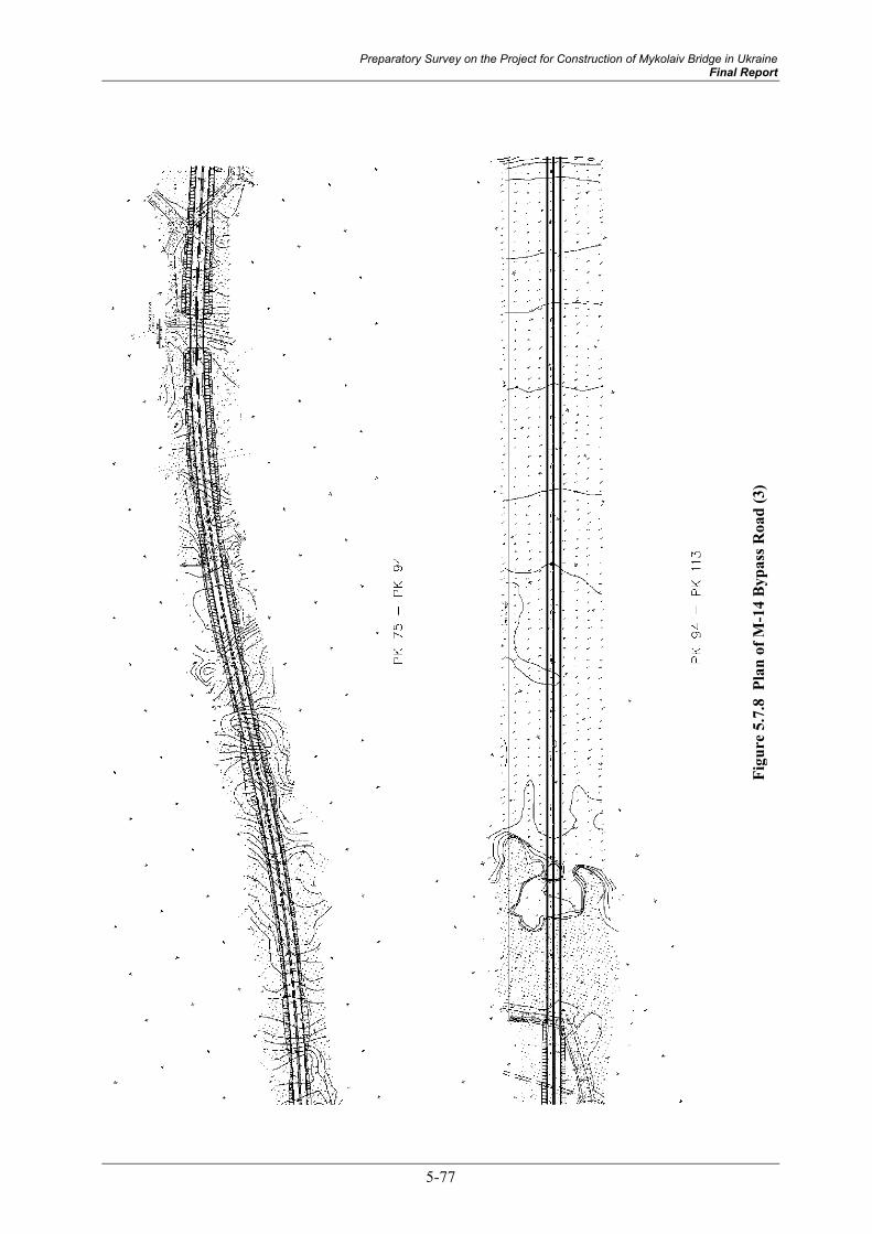
Preparatory Survey on the Project for Construction of Mykolaiv Bridge in Ukraine Final Report
5-77
Figu
re 5
.7.8
Pla
n of
M-1
4 B
ypas
s Roa
d (3
)

5-78
Figu
re 5
.7.9
Pla
n of
M-1
4 B
ypas
s Roa
d (4
)

Preparatory Survey on the Project for Construction of Mykolaiv Bridge in Ukraine Final Report
5-79
5.7.3 Design Condition Design Condition and contents of the design are shown in “Volume.2: Preliminary Design Drawings”.
5.7.4 Current Site Condition of M-14 Bypass Main current site conditions of M-14 bypass road are shown in the figures below.

5-80
Figu
re 5
.7.1
0 C
urre
nt S
ite C
ondi
tion
of M
-14
Byp
ass R
oad
(1)

Preparatory Survey on the Project for Construction of Mykolaiv Bridge in Ukraine Final Report
5-81
Figu
re 5
.7.1
1 C
urre
nt S
ite C
ondi
tion
of M
-14
Byp
ass R
oad
(2)

5-82
Figu
re 5
.7.1
2 C
urre
nt S
ite C
ondi
tion
of M
-14
Byp
ass R
oad
(3)

Preparatory Survey on the Project for Construction of Mykolaiv Bridge in Ukraine Final Report
5-83
Figu
re 5
.7.1
3 C
urre
nt S
ite C
ondi
tion
of M
-14
Byp
ass R
oad
(4)