chapter 5 and appendix a: a-1 through a-5 for now geometric transformations needed for animation a...
TRANSCRIPT

Chapter 5Chapter 5andand
Appendix A: A-1 through A-5 Appendix A: A-1 through A-5 for nowfor now
Geometric TransformationsGeometric TransformationsNeeded for Needed for AnimationAnimation
A Mathematics ChapterA Mathematics Chapter

22
IDEAL BACKGROUND FOR ANIMATION IN IDEAL BACKGROUND FOR ANIMATION IN GRAPHICSGRAPHICS
Need concepts fromNeed concepts from• analytical geometryanalytical geometry• trigonometrytrigonometry• linear algebralinear algebra• vector analysisvector analysis
Don't need memorized formulas, but intuitive Don't need memorized formulas, but intuitive concepts and a few basic formulas that can be concepts and a few basic formulas that can be understood visually.understood visually.
We'll take a very pragmatic and utilitarian approach.We'll take a very pragmatic and utilitarian approach. Approach will be similar to what we do all the Approach will be similar to what we do all the
time in computer science---deal with abstract time in computer science---deal with abstract data typesdata types

33
ABSTRACT DATA TYPE (ADT) APPROACHABSTRACT DATA TYPE (ADT) APPROACH
Initially, Initially, don't worry about internal don't worry about internal representationsrepresentations of these objects ---i.e. in computer of these objects ---i.e. in computer science, we capture concepts using the notions ofscience, we capture concepts using the notions of• a classa class• objects that are instantiated from the classobjects that are instantiated from the class
Concerned about Concerned about attributes attributes of classof class Concerned about Concerned about functions definedfunctions defined for the class for the class (Note: although many of you were introduced to (Note: although many of you were introduced to
these concepts while learning C++ or Java, the these concepts while learning C++ or Java, the above notions existed before these languages were above notions existed before these languages were designed.)designed.)
REMEMBER- "class" here is not a C++ class!!!REMEMBER- "class" here is not a C++ class!!!

44
MOTIVATION FOR ALL THISMOTIVATION FOR ALL THIS
• We require a knowledge of vectors and matrices We require a knowledge of vectors and matrices in order to understand animation, in particular:in order to understand animation, in particular:
MotionMotion Camera placementCamera placement How to change between the different How to change between the different
coordinate systemscoordinate systems• We require a knowledge of the representation of We require a knowledge of the representation of
lines, planes, and normals in order to lines, planes, and normals in order to understandunderstand
Rendering algorithmsRendering algorithms Lighting modelsLighting models
55
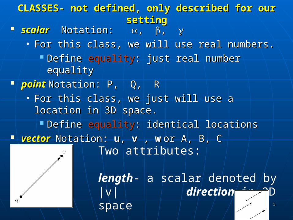
CLASSES- not defined, only described for our settingCLASSES- not defined, only described for our setting scalarscalar Notation: Notation: , , , ,
• For this class, we will use real numbers.For this class, we will use real numbers. Define Define equalityequality: just real number equality: just real number equality
pointpoint Notation: P, Q, RNotation: P, Q, R• For this class, we just will use a location in 3D For this class, we just will use a location in 3D
space.space. Define Define equalityequality: identical locations: identical locations
vector vector Notation: Notation: uu, , vv , , ww or A, B, Cor A, B, C
Two attributes: length- a scalar denoted by |v| direction in 3D space
Define equality: same length and direction
66
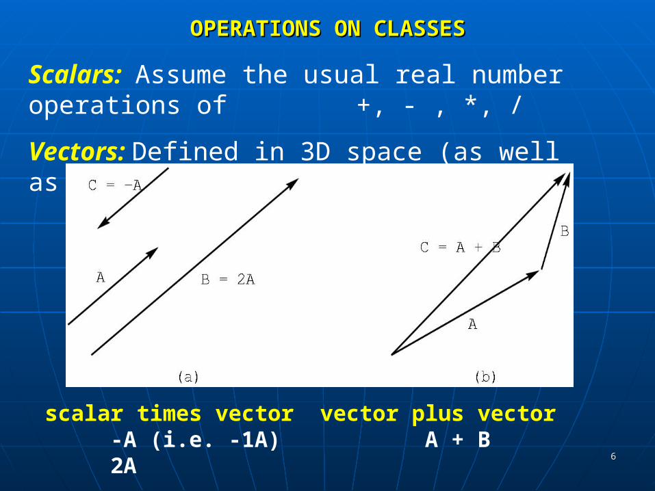
OPERATIONS ON CLASSESOPERATIONS ON CLASSES
Scalars: Assume the usual real number operations of +, - , *, /
Vectors: Defined in 3D space (as well as 2D)
scalar times vector-A (i.e. -1A)2A
vector plus vector A + B

77
VECTOR OPERATIONSVECTOR OPERATIONS
Perform addition by the head-to-tail rule.
u
vu+v
u
v+uNote that u + v = v + u.
To perform subtraction, we need the zero vector- i.e. vector with zero length and no direction.
v
-v
Note that v + (-v) = 0
88
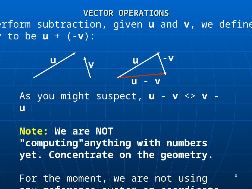
VECTOR OPERATIONSVECTOR OPERATIONSTo perform subtraction, given u and v, we defineu - v to be u + (-v):
u v u -v
u - v
As you might suspect, u - v <> v - u
Note: We are NOT "computing"anything with numbers yet. Concentrate on the geometry.
For the moment, we are not using any reference system or coordinate system.

99
VECTOR OPERATIONS:A bit of trigonometry VECTOR OPERATIONS:A bit of trigonometry
(cos , sin )
circle with radius 1
There are two ways to measure the size of an angle:
degrees and radian measure180o = radians
Some useful trigonometric values:
cos sin 0 1 0 /2 0 1 -1 0
Define u• v, the dot product, to be the scalar
|u| |v| cos , 0 <= <
and is the angle between u and v
We are most often concerned with the sign of u• v as it tells us about the angle between two vectors:
u• v > 0 iff 0 <= < 90o
u• v = 0 iff = 90o
u• v < 0 iff > 90o
1010
VECTOR OPERATIONS:A bit of trigonometryVECTOR OPERATIONS:A bit of trigonometry
(cos , sin )
circle with radius 1
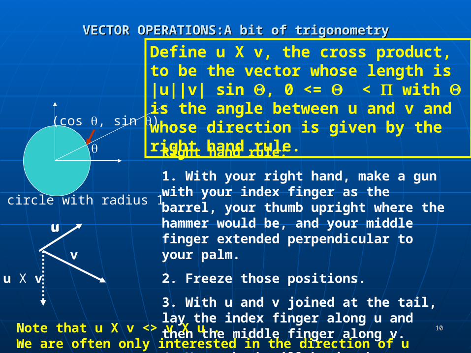
Right hand rule:
1. With your right hand, make a gun with your index finger as the barrel, your thumb upright where the hammer would be, and your middle finger extended perpendicular to your palm.
2. Freeze those positions.
3. With u and v joined at the tail, lay the index finger along u and then the middle finger along v.
4. Your thumb will be in the direction of u X v.
u
v
u X v
u
Note that u X v <> v X u . We are often only interested in the direction of u X v.
Define u X v, the cross product, to be the vector whose length is |u||v| sin , 0 <= < with is the angle between u and v and whose direction is given by the right hand rule.

1111
VECTOR OPERATIONSVECTOR OPERATIONS
Scalar times a vector( more details): Let be a scalar and u a vector.
Define
u to be the vector with length | ||u|
with the direction
of u if > 0
the opposite of u if < 0
and, of course, if = 0, the vector is the zero vector or a point.
u2u -3u
1212
POINT OPERATIONSPOINT OPERATIONS
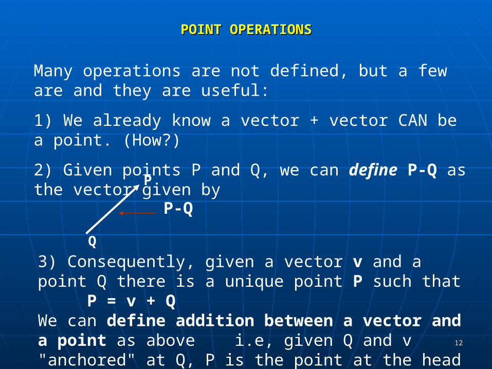
Many operations are not defined, but a few are and they are useful:
1) We already know a vector + vector CAN be a point. (How?)
2) Given points P and Q, we can define P-Q as the vector given by
Q
P
P-Q
3) Consequently, given a vector v and a point Q there is a unique point P such that
P = v + QWe can define addition between a vector and a point as above i.e, given Q and v "anchored" at Q, P is the point at the head of v.
1313
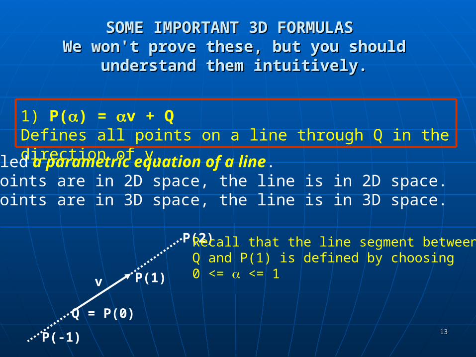
SOME IMPORTANT 3D FORMULAS SOME IMPORTANT 3D FORMULAS We won't prove these, but you should understand We won't prove these, but you should understand
them intuitively.them intuitively.
1) P() = v + Q Defines all points on a line through Q in the direction of v.
Also called a parametric equation of a line.If the points are in 2D space, the line is in 2D space.If the points are in 3D space, the line is in 3D space.
Q = P(0)
v
P(-1)
P(1)
P(2) Recall that the line segment betweenQ and P(1) is defined by choosing0 <= <= 1

1414
DEFINING A RESTRICTED FORM OF POINT ADDITIONDEFINING A RESTRICTED FORM OF POINT ADDITION
Start withP= P() = v + Q
Let v = R - Q for points R and Q, Then,P = (R-Q) + Q //substitute R-Q for v = R - Q + Q //distribute
= R + (1- )Q //regroup
So, we can define a restricted point addition asP = 1R +2Q , when 1 + 2= 1
Q
R
P()
R-Q
1515
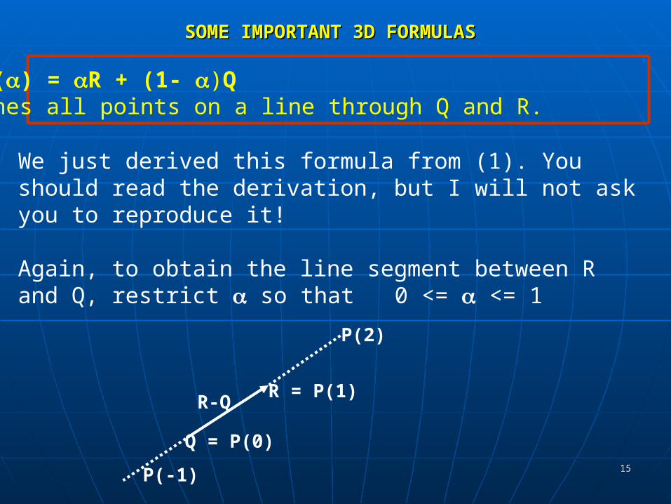
SOME IMPORTANT 3D FORMULASSOME IMPORTANT 3D FORMULAS
2) P() = R + (1- )Q Defines all points on a line through Q and R.
We just derived this formula from (1). You should read the derivation, but I will not ask you to reproduce it!
Again, to obtain the line segment between R and Q, restrict so that 0 <= <= 1
Q = P(0)
P(-1)
R = P(1)
P(2)
R-Q
1616
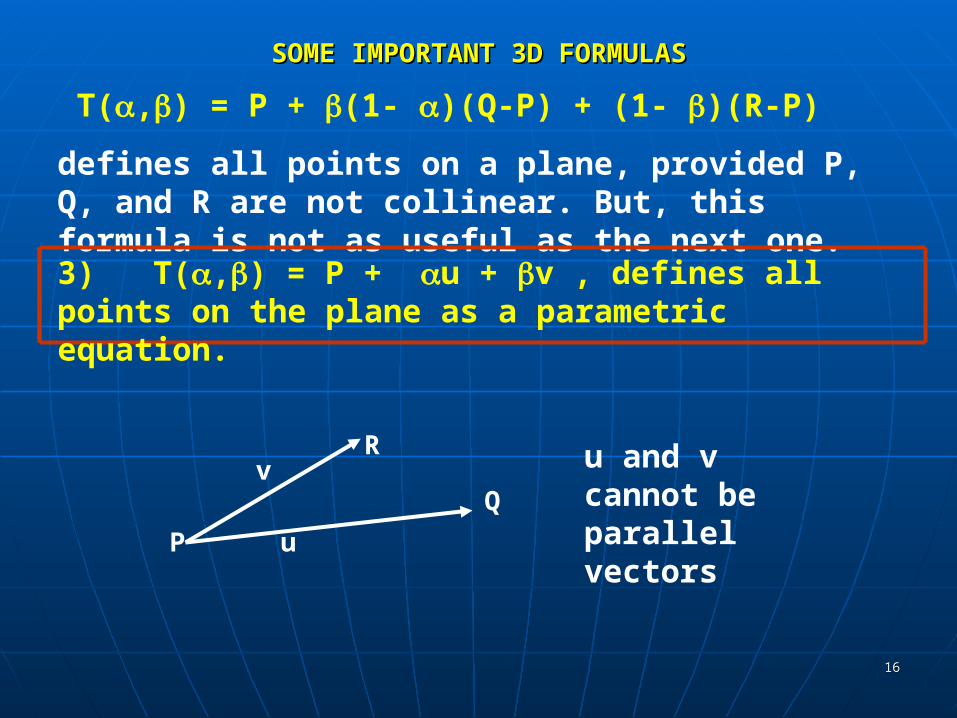
SOME IMPORTANT 3D FORMULASSOME IMPORTANT 3D FORMULAS
T(,) = P + (1- )(Q-P) + (1- )(R-P)
defines all points on a plane, provided P, Q, and R are not collinear. But, this formula is not as useful as the next one.
3) T(,) = P + u + v , defines all points on the plane as a parametric equation.
P
R
Qv
u
u and v cannot be parallel vectors

1717
Intuitively,Intuitively, T(,) = P + u + v , defines all points on the plane
P
R
Q
v
u
P + 1.25 u + 1.5v
(approximately)
1818
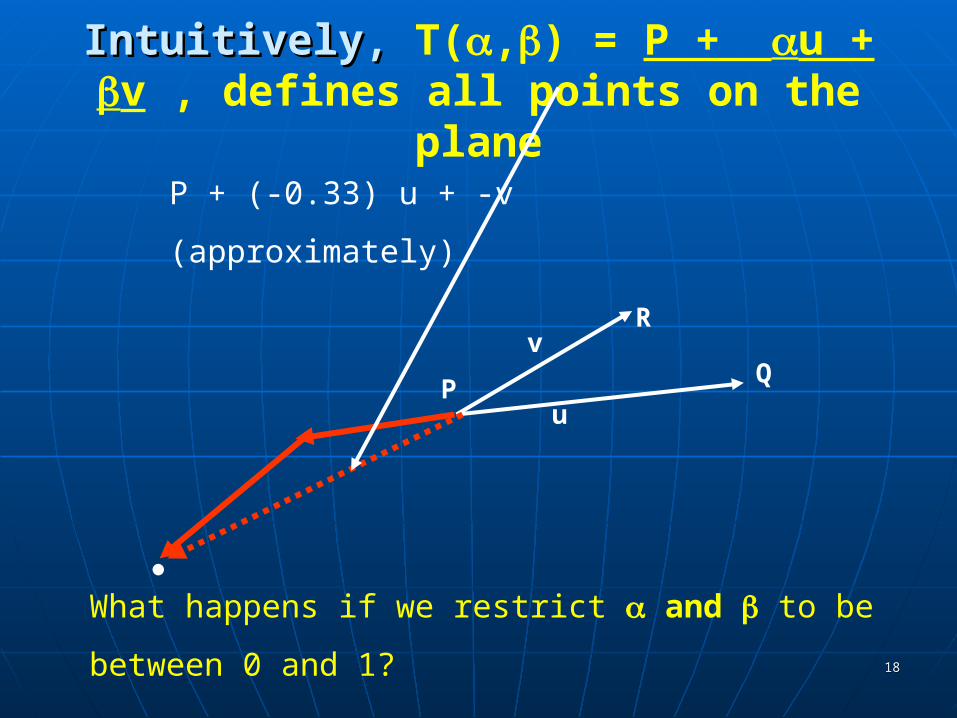
Intuitively,Intuitively, T(,) = P + u + v , defines all points on the plane
P
R
Qv
u
What happens if we restrict and to be
between 0 and 1?
P + (-0.33) u + -v
(approximately)
1919
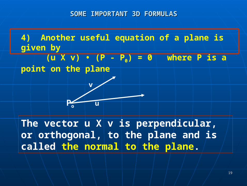
SOME IMPORTANT 3D FORMULASSOME IMPORTANT 3D FORMULAS
4) Another useful equation of a plane is given by(u X v) • (P - P0) = 0 where P is a point on the plane
Po
v
u
The vector u X v is perpendicular, or orthogonal, to the plane and is called the normal to the plane.
2020
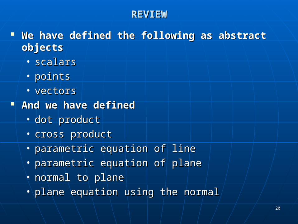
REVIEWREVIEW
We have defined the following as abstract We have defined the following as abstract objects objects • scalarsscalars• pointspoints• vectorsvectors
And we have definedAnd we have defined• dot productdot product• cross productcross product• parametric equation of lineparametric equation of line• parametric equation of planeparametric equation of plane• normal to planenormal to plane• plane equation using the normalplane equation using the normal

2121
NOTE THAT WE HAVEN'TNOTE THAT WE HAVEN'T
Seen how to “compute” anythingSeen how to “compute” anything Haven't had a coordinate system involved.Haven't had a coordinate system involved.
These concepts are NOT required in order to These concepts are NOT required in order to visualize what is happening with scalars, visualize what is happening with scalars, points, and vectors.points, and vectors.
Now, we have to add a coordinate system, Now, we have to add a coordinate system, but first we need some basic concepts from but first we need some basic concepts from analytical geometry.analytical geometry.

2222
MATRICESMATRICES
Definition: A matrix is an n X m array of scalars, arranged conceptually in n rows and m columns, where n and m are positive integers.
If n = m, we say the matrix is a square matrix.We often refer to a matrix with the notation
A = [a(i,j)] where a(i,j) denotes the scalar in the ith row and the jth column
We'll use A, B, and C to denote matrices.
Note that the text uses the typical mathematical notation where the i and j are subscripts. We'll use this alternative form as it is easier to type and it is more familiar to computer scientists.
2323
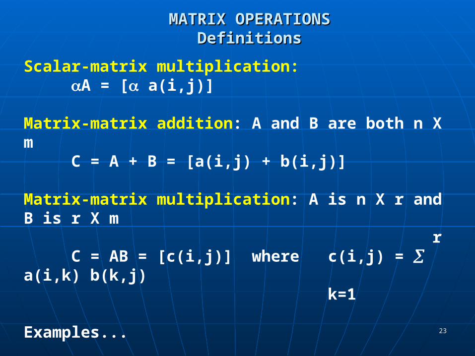
MATRIX OPERATIONSMATRIX OPERATIONSDefinitionsDefinitions
Scalar-matrix multiplication:A = [ a(i,j)]
Matrix-matrix addition: A and B are both n X mC = A + B = [a(i,j) + b(i,j)]
Matrix-matrix multiplication: A is n X r and B is r X m r
C = AB = [c(i,j)] where c(i,j) = a(i,k) b(k,j) k=1
Examples...

2424
MATRIX OPERATIONSMATRIX OPERATIONSExamplesExamples
Scalar-matrix multiplication:A = [ a(i,j)]
3 -1 15 -5 5 7 2 = 35 10 -1 6 -5 30
Matrix-matrix addition: A and B are both n X mC = A + B = [a(i,j) + b(i,j)]
3 -1 5 2 8 1 7 2 + 3 -1 = 10 1 -1 6 4 0 3 6

2525
MATRIX OPERATIONSMATRIX OPERATIONSExamplesExamples
Matrix-matrix multiplication: A is n X r and B is r X m r
C = AB = [c(i,j)] where c(i,j) = a(i,k) b(k,j) k=1
For example, 3 -1 1 2 1 -1 0 5 3 -1 c(2,3)= a(2,1)b(1,3) + 1 2 3 1 0 -2 = 7 4 1 -5 a(2,2)b(2,3)= 0 1 3 1 0 -2 1*1 + 2*0 = 1
must be the same Note that the following is undefined:1 2 1 -1 3 -1 because a 2 X 4 matrix can't be 3 1 0 -2 1 2 multiplied by a 3 X 2 matrix. 0 1 A 4 X m matrix is required.
2626
MATRIX OPERATIONSMATRIX OPERATIONSDefinitions (Continued)Definitions (Continued)
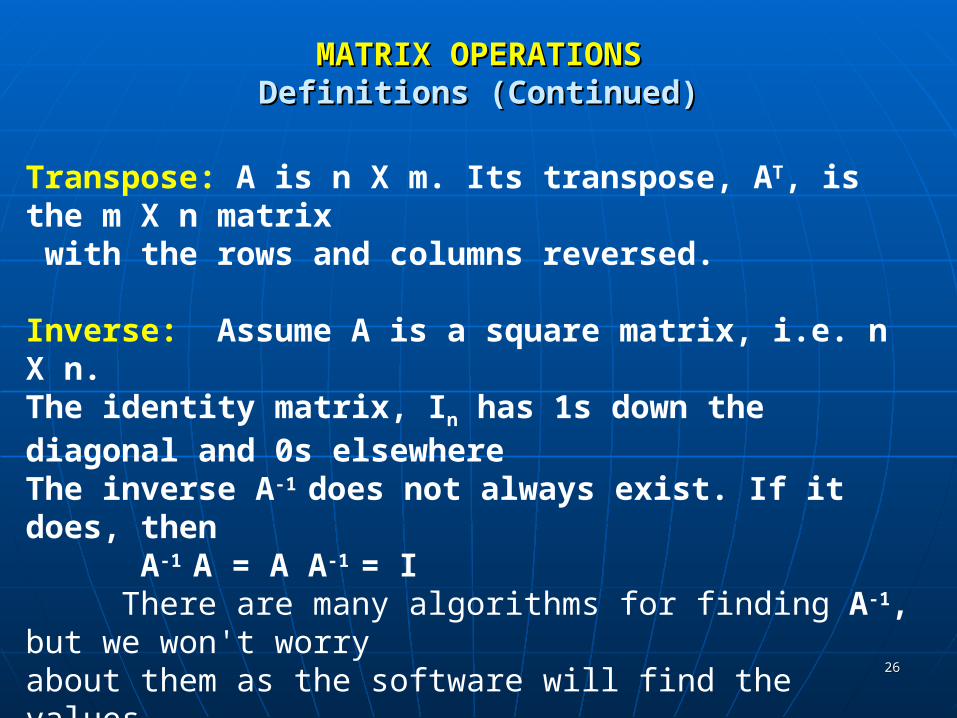
Transpose: A is n X m. Its transpose, AT, is the m X n matrix with the rows and columns reversed.
Inverse: Assume A is a square matrix, i.e. n X n. The identity matrix, In has 1s down the diagonal and 0s elsewhereThe inverse A-1 does not always exist. If it does, then
A-1 A = A A-1 = IThere are many algorithms for finding A-1, but we won't worry
about them as the software will find the values.
However, given a matrix A and another matrix B, we can check whether or not B is the inverse of A by computing AB and BA and seeing that AB = BA = In
More examples ...

2727
MATRIX OPERATIONSMATRIX OPERATIONSExamplesExamples
Transpose: A is n X m. Its transpose, AT, is the m X n matrix with the rows and columns reversed.1 2 1 4T = 1 33 1 0 5 2 1 1 0 4 5Inverse: Assume A is a square matrix, i.e. n X n. If A-1 exists, then A-1 A = A A-1 = I
1 0-1 1 02 3 = -2/3 1/3
because 1 0 1 0 1 0 1 0 1 0 2 3 -2/3 1/3 = -2/3 1/3 2 3 = 0 1
THIS DOES NOT SHOW HOW TO FIND THE INVERSE!
2828
BASISBASIS
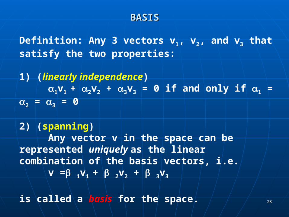
Definition: Any 3 vectors v1, v2, and v3 that satisfy the two properties:
1) (linearly independence)1v1 + 2v2 + 3v3 = 0 if and only if 1 = 2 = 3 = 0
2) (spanning)Any vector v in the space can be represented uniquely
as the linear combination of the basis vectors, i.e.v = 1v1 + 2v2 + 3v3
is called a basis for the space.
FACT: In 2D space, any basis needs 2 vectors. In 3D space, any basis needs 3 vectors.
2929
BASISBASIS
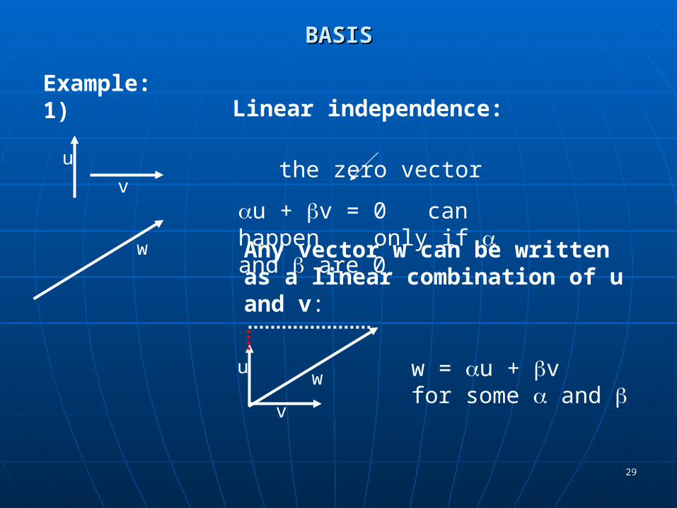
Example:1)
u
v
the zero vector
u + v = 0 can happen only if and are 0
v
w
w
Linear independence:
Any vector w can be written as a linear combination of u and v:
w = u + v for some and
u
3030
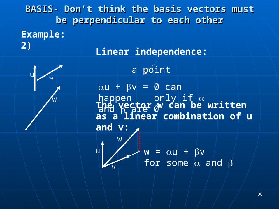
BASIS- Don't think the basis vectors must be BASIS- Don't think the basis vectors must be perpendicular to each otherperpendicular to each other
Example:2)
u
v
a point
u + v = 0 can happen only if and are 0
u
v
w
w
Linear independence:
The vector w can be written as a linear combination of u and v:
w = u + vfor some and
3131
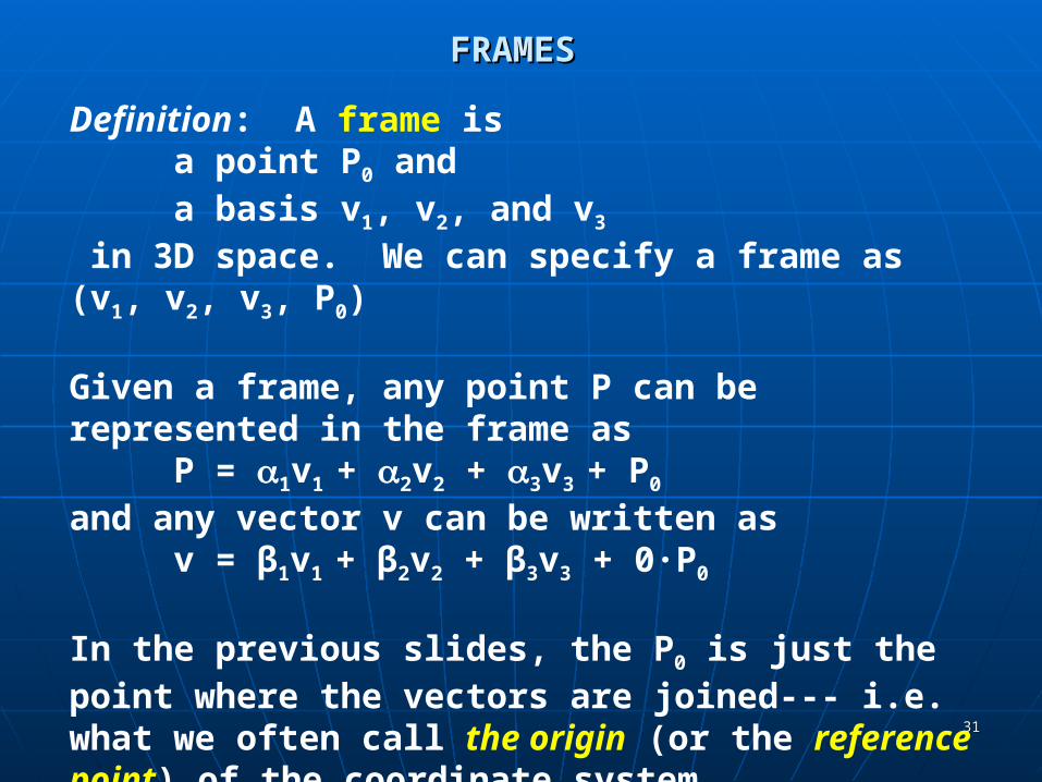
FRAMESFRAMES
Definition: A frame is a point P0 and a basis v1, v2, and v3
in 3D space. We can specify a frame as (v1, v2, v3, P0)
Given a frame, any point P can be represented in the frame asP = 1v1 + 2v2 + 3v3 + P0
and any vector v can be written as v = β1v1 + β2v2 + β3v3 + 0·P0
In the previous slides, the P0 is just the point where the vectors are joined--- i.e. what we often call the origin (or the reference point) of the coordinate system.
We will now use matrices to represent some of these concepts.

3232
HOMOGENEOUS COORDINATESHOMOGENEOUS COORDINATES
In many textbooks, a vector is associated with a point (x, y, z) where the x, y, and z represent the coordinates in the standard coordinate system.
This only works if we assume the frame we are using has the point (0,0,0) as the origin and the vector is positioned at the origin:
This causes confusion as thevector from (1,1,1) to (2,3,4)is the same vector as the one from(0,0,0) to (1,2,3) because the vectors have the same lengthand their directions are the same.

3333
HOMOGENEOUS COORDINATESHOMOGENEOUS COORDINATES
In graphics, In graphics, • we wish to keep points and vectors as we wish to keep points and vectors as
separate entitiesseparate entities• we wish to maintain frame information.we wish to maintain frame information.
We use homogeneous coordinates to represent We use homogeneous coordinates to represent points and vectors.points and vectors.
A A homogeneous coordinatehomogeneous coordinate is a 4D column or row is a 4D column or row matrix matrix
(This can be defined in projective geometry, but (This can be defined in projective geometry, but we don't need the definition here- only the we don't need the definition here- only the properties of a homogeneous coordinate--- it acts properties of a homogeneous coordinate--- it acts like any other matrix.)like any other matrix.)

3434
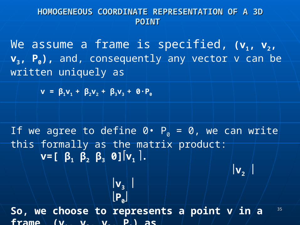
HOMOGENEOUS COORDINATE REPRESENTATION OF A 3D HOMOGENEOUS COORDINATE REPRESENTATION OF A 3D POINT POINT
We assume a frame is specified, (v1, v2, v3, P0), and, consequently any point P can be written uniquely as
P = 1v1 + 2v2 + 3v3 + P0
If we agree to define 1 • P = P, we can write this formally as the matrix product:
P=[ 1 2 3 1]v1. v2
v3 P0
So, we choose to represents a point P in a frame (v1, v2, v3, P0) ascolumn matrix: [ 1 2 3 1]
T
3535
HOMOGENEOUS COORDINATE REPRESENTATION OF A 3D HOMOGENEOUS COORDINATE REPRESENTATION OF A 3D POINT POINT
We assume a frame is specified, (v1, v2, v3, P0), and, consequently any vector v can be written uniquely as
v = β1v1 + β2v2 + β3v3 + 0·P0
If we agree to define 0• P0 = 0, we can write this formally as the matrix product:
v=[ β1 β2 β3 0]v1 . v2
v3 P0
So, we choose to represents a point v in a frame (v1, v2, v3, P0) ascolumn matrix: [ β1 β2 β3 0]
T
3636
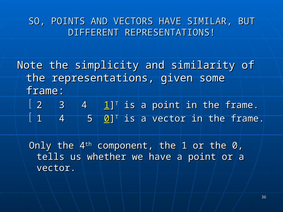
SO, POINTS AND VECTORS HAVE SIMILAR, BUT SO, POINTS AND VECTORS HAVE SIMILAR, BUT DIFFERENT REPRESENTATIONS!DIFFERENT REPRESENTATIONS!
Note the simplicity and similarity of the Note the simplicity and similarity of the representations, given some frame:representations, given some frame: 2 3 4 2 3 4 11]]TT is a point in the frame. is a point in the frame. 1 4 5 1 4 5 00]]TT is a vector in the frame. is a vector in the frame.
Only the 4Only the 4thth component, the 1 or the 0, tells us component, the 1 or the 0, tells us whether we have a point or a vector.whether we have a point or a vector.

3737
WHY WORRY ABOUT ALL OF THIS?WHY WORRY ABOUT ALL OF THIS?
We will define our objects in a physical frame.
The camera can be expressed in this frame, but it is more useful to switch to a camera frame where the origin is at the center of a projection.
Moreover, it will be most useful if we can define our
objects in a frame that is handy to use for computational purposes
and then SWITCH frames to a more natural one.
3838
MOTION OR ANIMATION IS JUST A FRAME CHANGE.
You can think of motion asholding the frame still
orholding the object still
and moving the object
and moving the frame!
3939
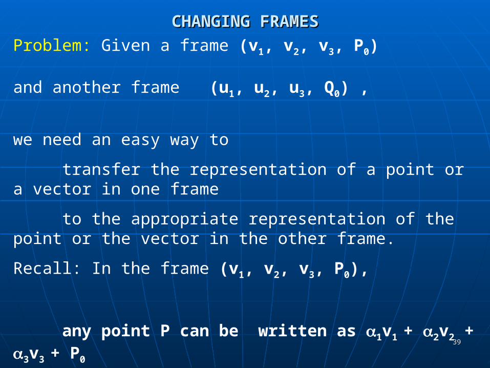
CHANGING FRAMESCHANGING FRAMES
Problem: Given a frame (v1, v2, v3, P0) and another frame (u1, u2, u3, Q0) ,
we need an easy way to
transfer the representation of a point or a vector in one frame
to the appropriate representation of the point or the vector in the other frame.
Recall: In the frame (v1, v2, v3, P0),
any point P can be written as 1v1 + 2v2 + 3v3 + P0
and any vector v can be written as 1v1 + 2v2 + 3v3
4040
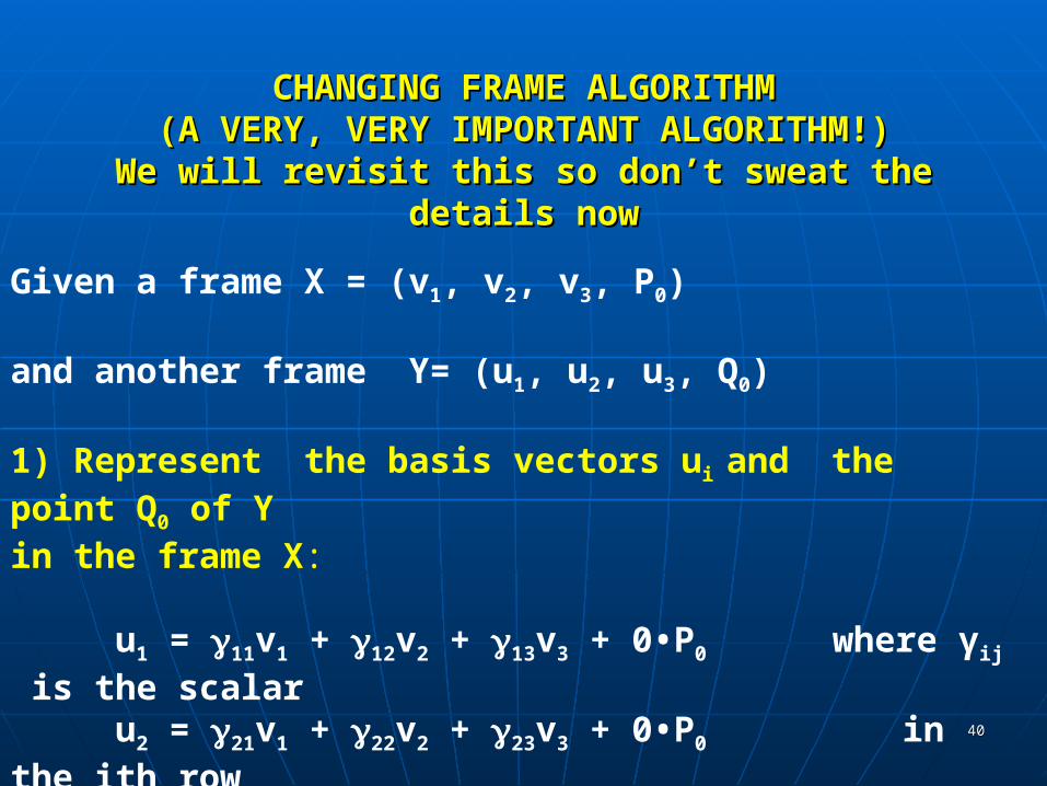
CHANGING FRAME ALGORITHMCHANGING FRAME ALGORITHM(A VERY, VERY IMPORTANT ALGORITHM!)(A VERY, VERY IMPORTANT ALGORITHM!)
We will revisit this so don’t sweat the details nowWe will revisit this so don’t sweat the details now
Given a frame X = (v1, v2, v3, P0) and another frame Y= (u1, u2, u3, Q0)
1) Represent the basis vectors ui and the point Q0 of Y in the frame X:
u1 = 11v1 + 12v2 + 13v3 + 0•P0 where γij is the scalaru2 = 21v1 + 22v2 + 23v3 + 0•P0 in the ith row u3 = 31v1 + 32v2 + 33v3 + 0•P0 and jth column.
Q0 = 41v1 + 42v2 + 43v3 + 1•P0
4141
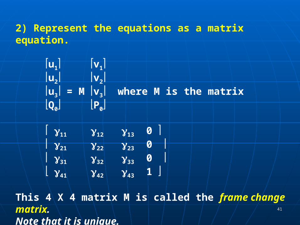
2) Represent the equations as a matrix equation.
u1 v1 u2 v2u3 = M v3 where M is the matrixQ0 P0
11 12 13 0 21 22 23 0 31 32 33 0 41 42 43 1
This 4 X 4 matrix M is called the frame change matrix.Note that it is unique.

4242
3) We can use the matrix M to compute for any point or vector its new representation in frame Y or conversely.
Let a be either a point or vector in X. Then a = MT b (convert Y frame to X frame)
orb= (MT)-1 a (convert X frame to Y frame)
where b is the corresponding point or vector in Y.
Thus, M allows us to move back and forth between frames!
4343
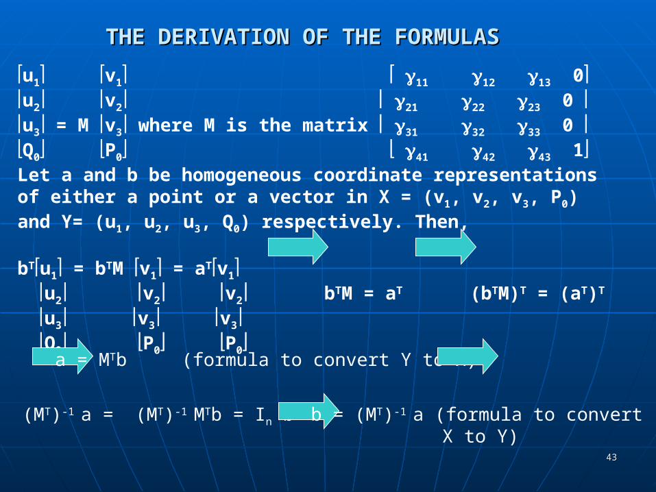
THE DERIVATION OF THE FORMULAS THE DERIVATION OF THE FORMULAS
u1 v1 11 12 13 0u2 v2 21 22 23 0 u3 = M v3 where M is the matrix 31 32 33 0 Q0 P0 41 42 43 1 Let a and b be homogeneous coordinate representations of either a point or a vector in X = (v1, v2, v3, P0) and Y= (u1, u2, u3, Q0) respectively. Then,
bTu1 = bTM v1 = aTv1 u2 v2 v2 bTM = aT (bTM)T = (aT)T
u3 v3 v3 Q0 P0 P0
a = MTb (formula to convert Y to X)
(MT)-1 a = (MT)-1 MTb = In b b = (MT)-1 a (formula to convert X to Y)

Frames and Affine Frames and Affine TransformationsTransformations

4545
FRAMES IN OPENGLFRAMES IN OPENGL We've seen that the representation of points and We've seen that the representation of points and
vectors are tied to frames.vectors are tied to frames. OpenGL maintains two framesOpenGL maintains two frames
• Camera frameCamera frame• World frameWorld frame
Initially, the two frames are the same with the Initially, the two frames are the same with the following orientation: following orientation:
x
y
z
Camera is pointing along thenegative z axis.
This is a right-handed system.
4646
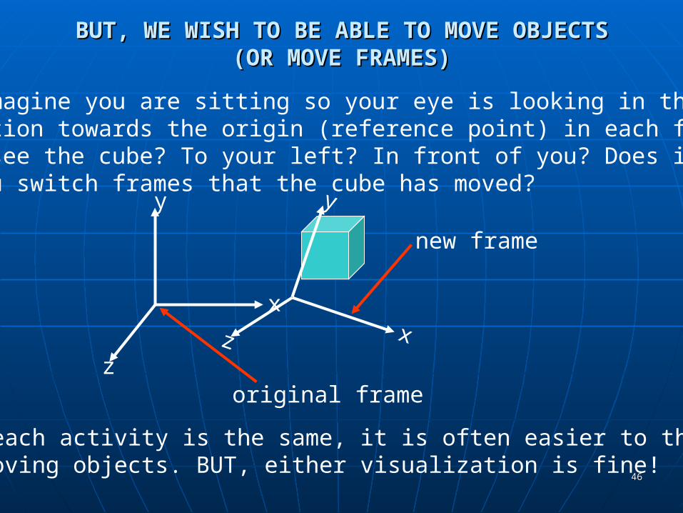
BUT, WE WISH TO BE ABLE TO MOVE OBJECTS BUT, WE WISH TO BE ABLE TO MOVE OBJECTS (OR MOVE FRAMES)(OR MOVE FRAMES)
x
y
zoriginal frame
new frame
Although each activity is the same, it is often easier to think thatyou are moving objects. BUT, either visualization is fine!
x
y
z
Hint: Imagine you are sitting so your eye is looking in the negativez direction towards the origin (reference point) in each frame. Wheredo you see the cube? To your left? In front of you? Does it appearwhen you switch frames that the cube has moved?

4747
THE USUAL SCENARIO IN OPENGLTHE USUAL SCENARIO IN OPENGL
Define objects around the origin in the default Define objects around the origin in the default setting.setting.
We want the viewing conditions to be such that the We want the viewing conditions to be such that the camera sees only those objects we wish it to see.camera sees only those objects we wish it to see.
So, we need to move So, we need to move • 1) the camera away from the objects or 1) the camera away from the objects or • 2) the objects away from the camera.2) the objects away from the camera.
Or, equivalently, we move Or, equivalently, we move • 1)' the camera frame relative to the world frame 1)' the camera frame relative to the world frame
oror• 2)' the world frame relative to the camera frame.2)' the world frame relative to the camera frame.
Normally, we view the camera as fixed and move the Normally, we view the camera as fixed and move the objects.objects.
4848
THE IMPORTANT MODEL-VIEW MATRIXTHE IMPORTANT MODEL-VIEW MATRIX
This is the 4 X 4 frame change matrix that is This is the 4 X 4 frame change matrix that is required to transform between camera required to transform between camera frame representations and world frame frame representations and world frame representations.representations.
We can change the matrix by loading the We can change the matrix by loading the necessary 16 scalars using glLoadMatrix.necessary 16 scalars using glLoadMatrix.
But, computing the 16 scalars is not an easy But, computing the 16 scalars is not an easy task as we have seen.task as we have seen.
It is easier, to equivalently move objects, It is easier, to equivalently move objects, using using affine transformationsaffine transformations..

4949
AFFINE TRANSFORMATIONSAFFINE TRANSFORMATIONS A A transformationtransformation is a function that maps a point is a function that maps a point
(or vector) into another point (or vector).(or vector) into another point (or vector). An An affine transformationaffine transformation is a transformation that is a transformation that
maps lines to lines.maps lines to lines.
We can define a polygon using only points and the line segments joining the points.
To move the polygon, if we use affine transformations, we only must map the points defining the polygon as the edges will be mapped to edges!
We can model many objects with polygons---and should--- for the above reason in many cases.
Why are affine transformations "nice"?

5050
AFFINE TRANSFORMATIONSAFFINE TRANSFORMATIONS
VERY IMPORTANT FACT:VERY IMPORTANT FACT: Any affine Any affine transformation can be obtained by transformation can be obtained by applying, in sequence, transformations applying, in sequence, transformations of the formof the form• TranslateTranslate• ScaleScale• Rotate- 3 different types in 3D spaceRotate- 3 different types in 3D space
So, to move an object all we have to do is So, to move an object all we have to do is determine the sequence of transformations determine the sequence of transformations we want using the 3 types of affine we want using the 3 types of affine transformations above.transformations above.
5151
FOR EACH AFFINE TRANSFORMATION WE FOR EACH AFFINE TRANSFORMATION WE NEED TO KNOW:NEED TO KNOW:
What does the transformation do?What does the transformation do? What matrix can be used to transform What matrix can be used to transform
the original points to the new points?the original points to the new points?
Recall--- moving an object is the same Recall--- moving an object is the same as changing a frame so we know we as changing a frame so we know we need a 4 X 4 matrixneed a 4 X 4 matrix
It is important to remember the form of It is important to remember the form of these matrices!!!these matrices!!!
5252
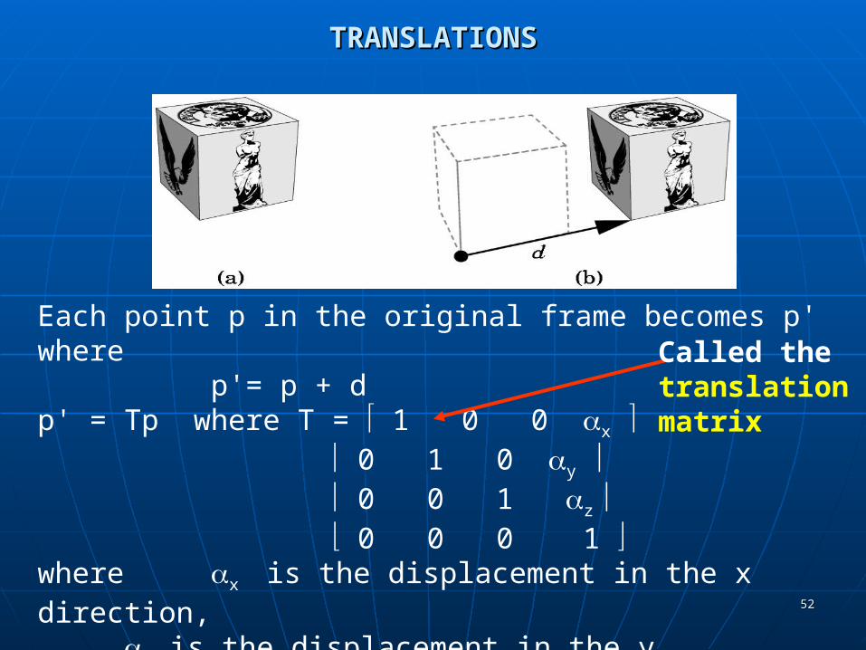
TRANSLATIONSTRANSLATIONS
Each point p in the original frame becomes p' wherep'= p + d
p' = Tp where T = 1 0 0 x 0 1 0 y 0 0 1 z 0 0 0 1 where x is the displacement in the x direction,
y is the displacement in the y direction, andz is the displacement in the z direction.
Write T as T(x, y, z)
Called thetranslationmatrix
5353
TRANSLATIONSTRANSLATIONS
x
y
z
x
y
z
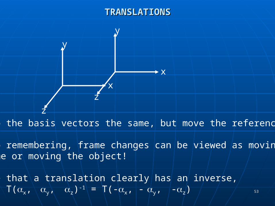
Keep the basis vectors the same, but move the reference point.
Keep remembering, frame changes can be viewed as moving the frame or moving the object!
Note that a translation clearly has an inverse,T(x, y, z)-1 = T(-x, - y, -z)
5454
TRANSLATIONS- 2DTRANSLATIONS- 2D
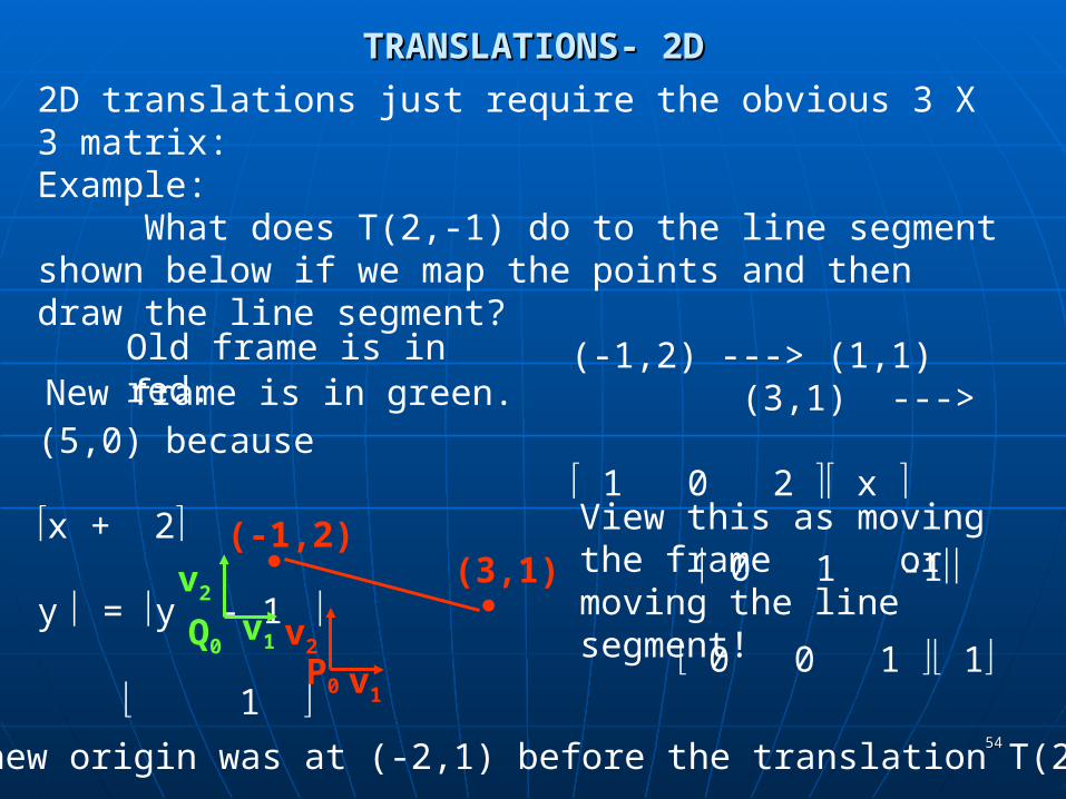
2D translations just require the obvious 3 X 3 matrix:Example:
What does T(2,-1) do to the line segment shown below if we map the points and then draw the line segment?
(-1,2) ---> (1,1) (3,1) ---> (5,0) because
1 0 2 x x + 2 0 1 -1 y = y - 1
0 0 1 1 1
v1P0
v2
(-1,2)(3,1)
v1Q0
v2
View this as moving the frame or
moving the line segment!
Note the new origin was at (-2,1) before the translation T(2,-1)
Old frame is in red.New frame is in green.
5555
TRANSLATIONS- 2D or 3DTRANSLATIONS- 2D or 3D
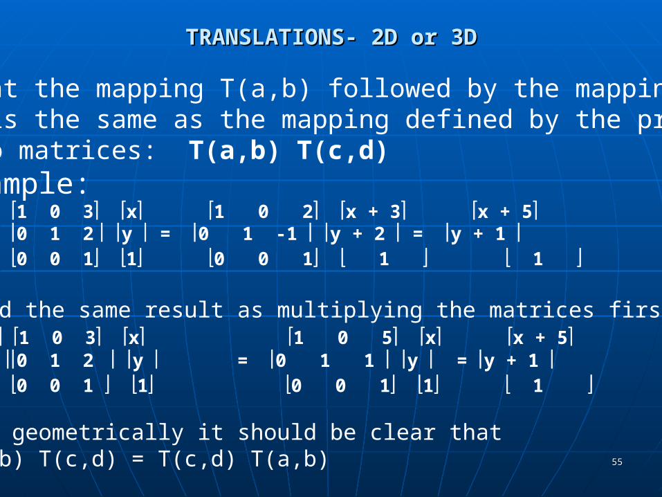
Note that the mapping T(a,b) followed by the mapping T(c,d) is the same as the mapping defined by the product of the two matrices: T(a,b) T(c,d)For example:1 0 2 1 0 3 x 1 0 2 x + 3 x + 5 0 1 -1 0 1 2 y = 0 1 -1 y + 2 = y + 1 0 0 1 0 0 1 1 0 0 1 1 1 will yield the same result as multiplying the matrices first: 1 0 2 1 0 3 x 1 0 5 x x + 5 0 1 -1 0 1 2 y = 0 1 1 y = y + 1 0 0 1 0 0 1 1 0 0 1 1 1
Moreover, geometrically it should be clear thatT(a,b) T(c,d) = T(c,d) T(a,b)
5656
ROTATIONS- 2D ROTATIONS- 2D INITIALLY AROUND THE ORIGININITIALLY AROUND THE ORIGIN
x
y
(x,y)•
•
(x',y')
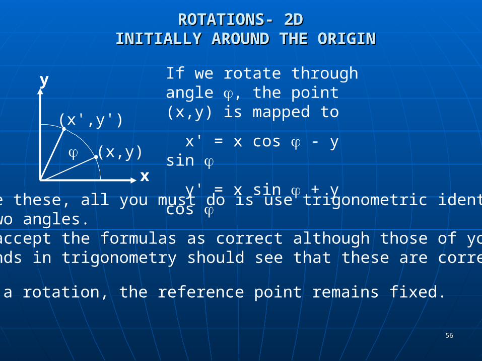
If we rotate through angle , the point (x,y) is mapped to
x' = x cos - y sin
y' = x sin + y cos
To derive these, all you must do is use trigonometric identities for thesum of two angles.We will accept the formulas as correct although those of you withbackgrounds in trigonometry should see that these are correct.
With a rotation, the reference point remains fixed.

5757
ROTATIONS- 2D ROTATIONS- 2D INITIALLY AROUND THE ORIGININITIALLY AROUND THE ORIGIN
For the rotation through angle , centered at the origin, the point (x,y) is mapped to
x' = x cos - y sin
y' = x sin + y cos
so the 2D rotation matrix R( ) is cos -sin 0
sin cos 0 0 0 1 Using the fact that cos(- ) = cos and sin(- ) = - sin we can show that R-1() = RT() = R(- )
5858
ROTATIONS- 2D ROTATIONS- 2D AROUND AN ARBITRARY POINTAROUND AN ARBITRARY POINT
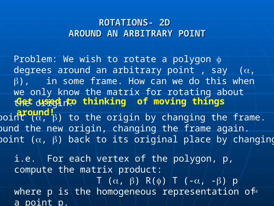
Problem: We wish to rotate a polygon degrees around an arbitrary point , say (, ), in some frame. How can we do this when we only know the matrix for rotating about the origin?
Get used to thinking of moving things around!
Move the point (, ) to the origin by changing the frame.Rotate around the new origin, changing the frame again.Move the point (, ) back to its original place by changing the frame.
i.e. For each vertex of the polygon, p, compute the matrix product: T (, ) R() T (-, -) pwhere p is the homogeneous representation of a point p.

IF SOMETHING ISN'T WHERE YOU IF SOMETHING ISN'T WHERE YOU WANT IT ….WANT IT ….
MOVE THE FRAMEMOVE THE FRAME
OR MOVE THE OBJECT

6060
ROTATIONS- 3D ROTATIONS- 3D INITIALLY AROUND THE ORIGININITIALLY AROUND THE ORIGIN
3D rotations are a bit more complicated as there is not just one basic rotation around the origin.
There are 3 basic rotations:1) Around the x axis.2) Around the y axis.3) Around the z axis.
We need to establish some conventions, however, that were ignored in the 2D case as the picture implied the answers to these questions:
1) How do we distinguish a positive angle from a negative angle?2) How do we measure the angle?

6161
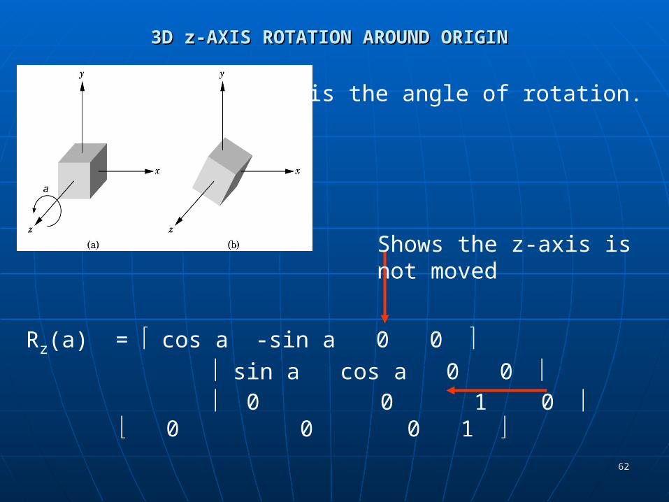
3D z-AXIS ROTATION AROUND ORIGIN3D z-AXIS ROTATION AROUND ORIGIN
The picture shows a z-axis rotation around the origin in a positive angle, a, direction.
i.e. counterclockwise as you look down the z-axis towards the origin.
The angle is measured in the xy-plane from the x-axis, just as the 2D angle was measured.
It can be shown that a point (x,y,z)is computed using the same formulasfor x' and y'.
Since z is not changed, z' = z. Thus, this rotation matrix iscomputed in the same way as the 2D matrix ...
6262
3D z-AXIS ROTATION AROUND ORIGIN3D z-AXIS ROTATION AROUND ORIGIN
Rz(a) = cos a -sin a 0 0 sin a cos a 0 0 0 0 1 0 0 0 0 1
Shows the z-axis isnot moved
a is the angle of rotation.
6363
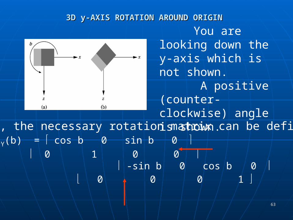
3D y-AXIS ROTATION AROUND ORIGIN3D y-AXIS ROTATION AROUND ORIGIN
You are looking down the y-axis which is not shown. A positive (counter-clockwise) angle is shown.
Again, the necessary rotation matrix can be defined:RY(b) = cos b 0 sin b 0
0 1 0 0 -sin b 0 cos b 0
0 0 0 1
6464
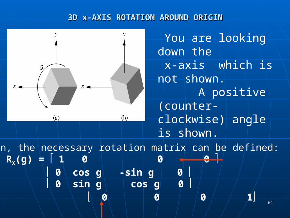
3D x-AXIS ROTATION AROUND ORIGIN3D x-AXIS ROTATION AROUND ORIGIN
You are looking down the x-axis which is not shown. A positive (counter-clockwise) angle is shown.
Again, the necessary rotation matrix can be defined:RX(g) = 1 0 0 0
0 cos g -sin g 0 0 sin g cos g 0
0 0 0 1
6565
ARBITRARY ROTATIONS IN 3D SPACEARBITRARY ROTATIONS IN 3D SPACE
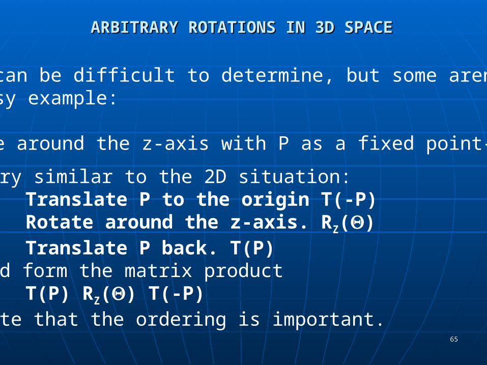
Some can be difficult to determine, but some aren't:An easy example:
Rotate around the z-axis with P as a fixed point---
Very similar to the 2D situation:Translate P to the origin T(-P)Rotate around the z-axis. RZ()Translate P back. T(P)
and form the matrix product T(P) RZ() T(-P)Note that the ordering is important.
6666
ARBITRARY ROTATIONS IN 3D SPACEARBITRARY ROTATIONS IN 3D SPACE
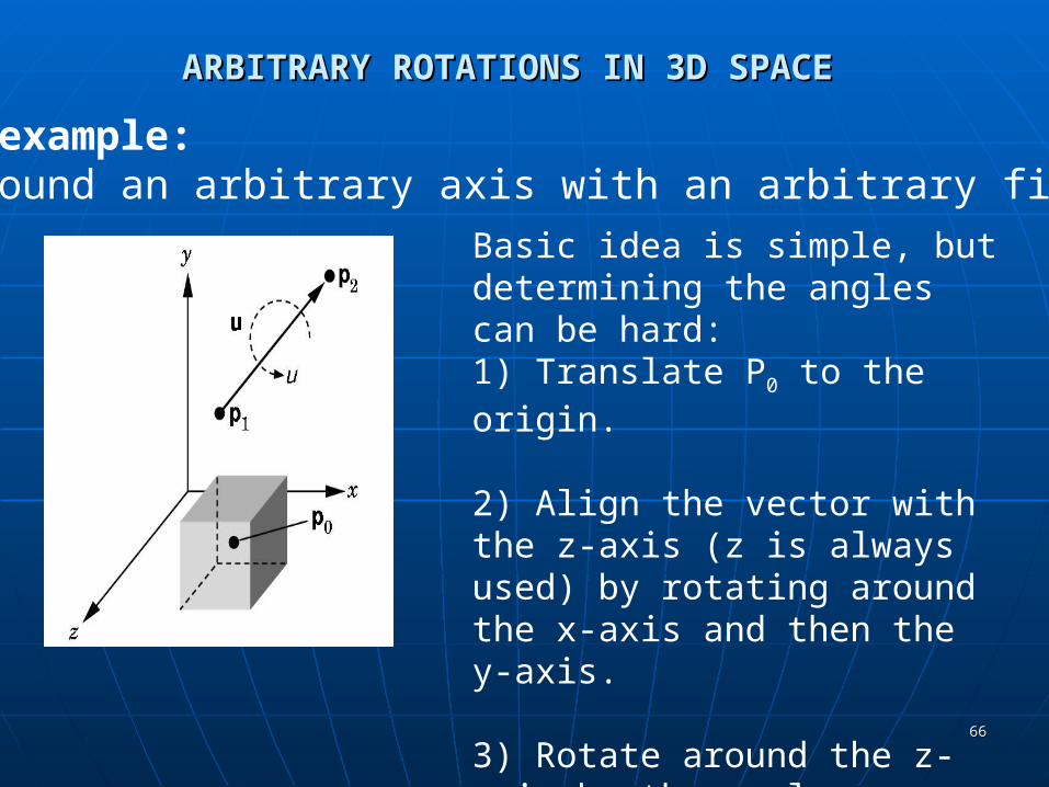
A harder example: Rotate around an arbitrary axis with an arbitrary fixed point.
Basic idea is simple, but determining the angles can be hard:1) Translate P0 to the origin.
2) Align the vector with the z-axis (z is always used) by rotating around the x-axis and then the y-axis.
3) Rotate around the z-axis by the angle desired.
4) Undo (2) and then (1).
6767
ARBITRARY ROTATIONS IN 3D SPACEARBITRARY ROTATIONS IN 3D SPACE
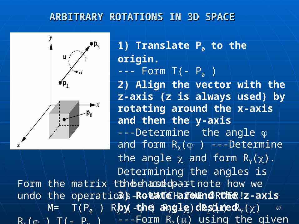
1) Translate P0 to the origin.--- Form T(- P0 )2) Align the vector with the z-axis (z is always used) by rotating around the x-axis and then the y-axis---Determine the angle and form RX( ) ---Determine the angle and form RY(). Determining the angles is the hard part.3) Rotate around the z-axis by the angle desired.---Form RZ() using the given angle .
Form the matrix to be used--- note how we undo the operations---WATCH THE ORDER!
M= T(P0 ) RX (- ) RY(-) RZ() RY() RX( ) T(- P0 )
6868
ARBITRARY ROTATIONS IN 3D SPACEARBITRARY ROTATIONS IN 3D SPACE Several different ways of deriving the Several different ways of deriving the
specific formulas for arbitrary rotation in specific formulas for arbitrary rotation in 3D space:3D space:• a) The method presented here . (See pgs 266-a) The method presented here . (See pgs 266-
269)269)• b) The use of the vector dot product to b) The use of the vector dot product to
establish the sin of angle and the use of the establish the sin of angle and the use of the vector cross product to determine the cosin of vector cross product to determine the cosin of the angle. (See pgs 269-272)the angle. (See pgs 269-272)
• c) The use of quaternions. (See pgs 272-273)c) The use of quaternions. (See pgs 272-273) You should be comfortable with using (a) You should be comfortable with using (a)
to conceptually establish the formulas. I to conceptually establish the formulas. I will not ask you to actually calculate the will not ask you to actually calculate the necessary angles.necessary angles.
6969
SCALINGSCALING
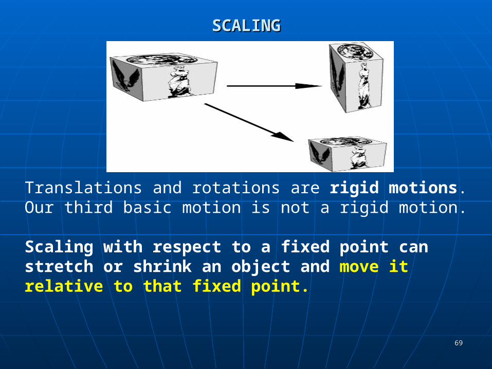
Translations and rotations are rigid motions. Our third basic motion is not a rigid motion.
Scaling with respect to a fixed point can stretch or shrink an object and move it relative to that fixed point.
7070
SCALINGSCALING
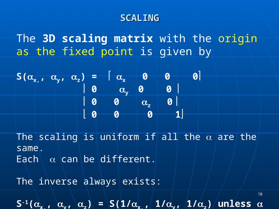
The 3D scaling matrix with the origin as the fixed point is given by
S(x,, y, z) = x 0 0 0 0 y 0 0 0 0 z 0 0 0 0 1
The scaling is uniform if all the are the same.Each can be different.
The inverse always exists:
S-1(x,, y, z) = S(1/x,, 1/y, 1/z) unless = 0. Then just use 0 instead.

7171
2D SCALING EXAMPLES2D SCALING EXAMPLES
Vertices are (4,2), (10,2), (4,4), (10,4)
Uniformly scale by 1/2:Vertices are (2,1), (5,1), (2,2), (5,2)
Not only has the rectangle shrunk,but it has moved closer to the origin.
What happens if you uniformly scale by 2?
What happens if a vertex is on an axis?
7272
2D SCALING EXAMPLES2D SCALING EXAMPLES
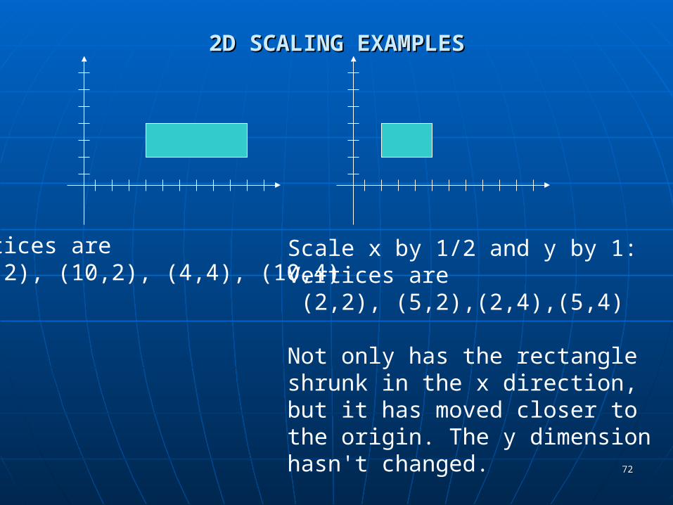
Vertices are (4,2), (10,2), (4,4), (10,4)
Scale x by 1/2 and y by 1:Vertices are (2,2), (5,2),(2,4),(5,4)
Not only has the rectangle shrunk in the x direction, but it has moved closer to the origin. The y dimension hasn't changed.
7373
SCALING EXAMPLESSCALING EXAMPLES
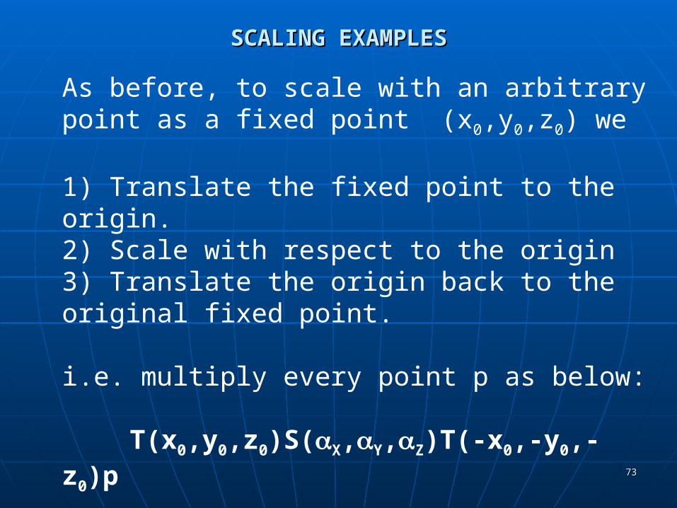
As before, to scale with an arbitrary point as a fixed point (x0,y0,z0) we
1) Translate the fixed point to the origin.2) Scale with respect to the origin3) Translate the origin back to the original fixed point.
i.e. multiply every point p as below:
T(x0,y0,z0)S(X,Y,Z)T(-x0,-y0,-z0)p

7474
Other 3D TransformationsOther 3D Transformations Only translations, rotations, and scales are Only translations, rotations, and scales are
required to describe any motion in 3D required to describe any motion in 3D space. These are called the space. These are called the primitiveprimitive or or basic basic 3D (or 2D) motions. There are 5 in 3D (or 2D) motions. There are 5 in 3D space and 3 in 2D space.3D space and 3 in 2D space.
However, several others are useful to However, several others are useful to single out.single out.• 3D Reflections3D Reflections• 3D Shears3D Shears
These are all affine transformations, These are all affine transformations, although they are not the basic (or although they are not the basic (or primitive) affine transformations.primitive) affine transformations.
7575
3D Reflections3D Reflections We can perform reflections relative to a selected We can perform reflections relative to a selected
reflection axis reflection axis or with respect to a or with respect to a reflection reflection plane.plane.
Reflections relative to a given axis are equivalent Reflections relative to a given axis are equivalent to 180° rotations about that axis.to 180° rotations about that axis.
Reflections with respect to a plane are equivalent Reflections with respect to a plane are equivalent to 180° rotations in 4D space.to 180° rotations in 4D space.
Rotations around the coordinate planes xy, xz, or Rotations around the coordinate planes xy, xz, or yz are the easiest to visualize.yz are the easiest to visualize.
For example, a useful reflection relative to a For example, a useful reflection relative to a plane is the conversion of a right-handed plane is the conversion of a right-handed coordinate system into a left-handed coordinate coordinate system into a left-handed coordinate system. (See next slide)system. (See next slide)

7676
A Simple Reflection Relative to a PlaneA Simple Reflection Relative to a Plane
MMzreflect zreflect = =
Reflection relative to the xy plane
z
x
y
x
y
z
1 0 0 0 0 1 0 0 0 0 -1 0 0 0 0 1
Reflections about other planes can be obtained as a combination of rotations and coordinate-plane reflections.
7777
3D Shears3D Shears
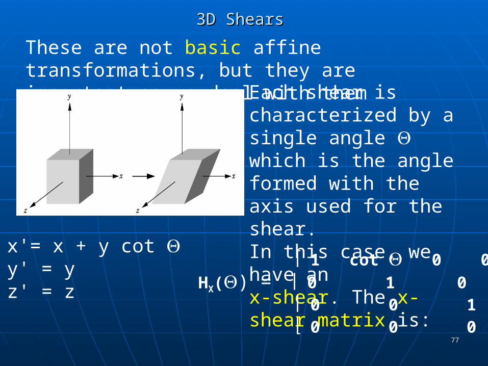
These are not basic affine transformations, but they are important so we deal with them separately:
Each shear is characterized by a single angle which is the angle formed with the axis used for the shear.In this case, we have an x-shear. The x-shear matrix is:
1 cot 0 0 HX() = 0 1 0 0 0 0 1 0 0 0 0 1
x'= x + y cot y' = yz' = z
7878
A BETTER APPROACH TO SHEARSA BETTER APPROACH TO SHEARS
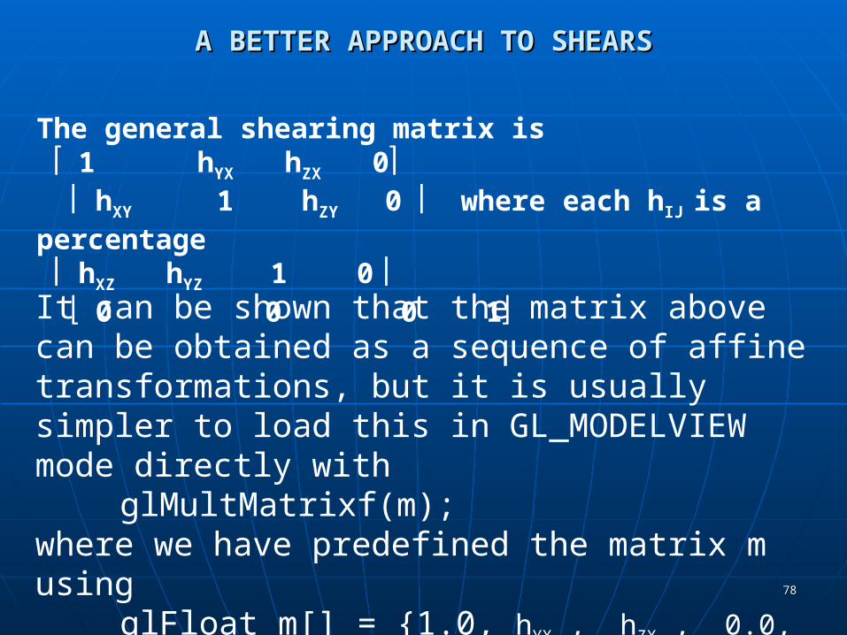
The general shearing matrix is 1 hYX hZX 0 hXY 1 hZY 0 where each hIJ is a percentage hXZ hYZ 1 0 0 0 0 1It can be shown that the matrix above can be obtained as a sequence of affine transformations, but it is usually simpler to load this in GL_MODELVIEW mode directly with
glMultMatrixf(m);where we have predefined the matrix m using
glFloat m[] = {1.0, hYX , hZX , 0.0, //row 1 hXY, 1.0, hZY, 0.0, //row 2
…}It is interesting to play with the different shears.

7979
Summary – Affine TransformationsSummary – Affine Transformations
Affine transformations preserve linesAffine transformations preserve lines – i.e. – i.e. if the endpoints of a line are transformed if the endpoints of a line are transformed by an affine transformation and then the by an affine transformation and then the line segment between them is drawn, line segment between them is drawn, then, equivalently, we could transform all then, equivalently, we could transform all points between and including the points between and including the endpoints and obtain the same results.endpoints and obtain the same results.
Thus, to transform a polygon, it suffices to Thus, to transform a polygon, it suffices to transform each of its vertices and then transform each of its vertices and then draw the line segments between them.draw the line segments between them.
8080
Summary - Affine TransformationsSummary - Affine Transformations
TranslationsTranslations RotationsRotations ScalesScales ReflectionsReflections ShearsShears
The first three suffice to mimic ANY 3D (or The first three suffice to mimic ANY 3D (or 2D) motion as a finite sequence of these 2D) motion as a finite sequence of these three transformations that are composited three transformations that are composited (i.e. function multiplied.)(i.e. function multiplied.)
8181
Summary - Affine TransformationsSummary - Affine Transformations
Affine transformations transform parallel Affine transformations transform parallel line segments into parallel line segments line segments into parallel line segments and a finite number of points into a finite and a finite number of points into a finite number of points.number of points.
An affine transformation involving only An affine transformation involving only translations, rotations, and reflections translations, rotations, and reflections preserves angles, lengths, and parallel line preserves angles, lengths, and parallel line segments.segments.

8282
DOING ALL THESE NEAT THINGS IN OPENGLDOING ALL THESE NEAT THINGS IN OPENGLModeling a Rotating CubeModeling a Rotating Cube
The simplest object we can model is a cube.
We number the vertices so we can refer to them.
There are several decisions we must make.
1) Will we view this as a primitive object that we manipulate?2) Will we view this as only a collection of 8 vertices that the hardware manipulates?
OpenGL programming tends to encourage a middle ground- we view this as made up of the six polygons that define the faces , or facets, of the cube.
0 1
23
4 5
7

8383
Modeling a Rotating CubeModeling a Rotating Cube
GLfloat vertices[][3] = {{-1.0,-1.0,-1.0},{1.0,-1.0,-1.0},{1.0,1.0,-1.0}, {-1.0,1.0,-1.0}, {-1.0,-1.0,1.0}, {1.0,-1.0,1.0}, {1.0,1.0,1.0}, {-1.0,1.0,1.0}};
But, we want to view this as more than a collection of vertices. We want to include the faces.
6
0 1
23
4 5
7
We usually build objects in OpenGL initially at the origin.
So, this cube will be centered at the origin.
The coordinates are chosen to be simple as we can scale in the future.
8484
Modeling a Rotating CubeModeling a Rotating Cube
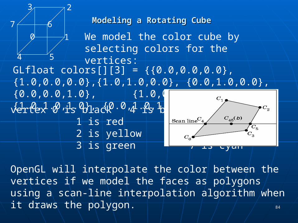
GLfloat colors[][3] = {{0.0,0.0,0.0},{1.0,0.0,0.0},{1.0,1.0,0.0}, {0.0,1.0,0.0}, {0.0,0.0,1.0}, {1.0,0.0,1.0}, {1.0,1.0,1.0}, {0.0,1.0,1.0}};
0 1
23
4 5
7
We model the color cube by selecting colors for the vertices:
vertex 0 is black 4 is blue 1 is red 5 is magenta 2 is yellow 6 is white 3 is green 7 is cyan
OpenGL will interpolate the color between the vertices if we model the faces as polygons using a scan-line interpolation algorithm when it draws the polygon.
6
8585
Modeling a Rotating CubeModeling a Rotating Cube
0 1
23
4 5
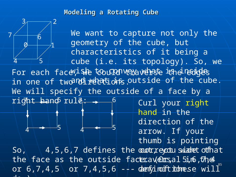
7 6 We want to capture not only the geometry of the cube, but characteristics of it being a cube (i.e. its topology). So, we wish to convey what is inside and what is outside of the cube.
For each face, we could traverse the edges in one of two directions.We will specify the outside of a face by a right hand rule:
67
4 5
67
4 5
Curl your right hand in the direction of the arrow. If your thumb is pointing out, you want that traversal in the definition.
So, 4,5,6,7 defines the correct side of the face as the outside face. (Or, 5,6,7,4 or 6,7,4,5 or 7,4,5,6 --- any of these will do.)
8686
Modeling a Rotating CubeModeling a Rotating Cube
Vertex normals (or Gouraud normals) are needed for shading or the interpolation of color.
Gouraud normals are defined as the sum of the normals of the polygons intersecting at a point.
For the cube centered at the origin, they are easy to calculate: Each vector is positioned from the origin to the vertex of the cube---i.e. GLfloat normals[][3] = {{-1.0,-1.0,-1.0},{1.0,-1.0,-1.0},{1.0,1.0,-1.0}, {-1.0,1.0,-1.0}, {-1.0,-1.0,1.0}, {1.0,-1.0,1.0}, {1.0,1.0,1.0}, {-1.0,1.0,1.0}};
glNormal3f(pointer_to_normal) associates the normal with a vertex.
8787
Modeling a Rotating CubeModeling a Rotating Cube
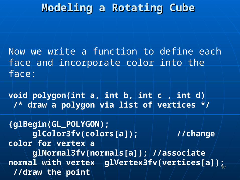
Now we write a function to define each face and incorporate color into the face:
void polygon(int a, int b, int c , int d) /* draw a polygon via list of vertices */
{glBegin(GL_POLYGON);glColor3fv(colors[a]); //change color for vertex aglNormal3fv(normals[a]); //associate normal with vertexglVertex3fv(vertices[a]); //draw the point
8888
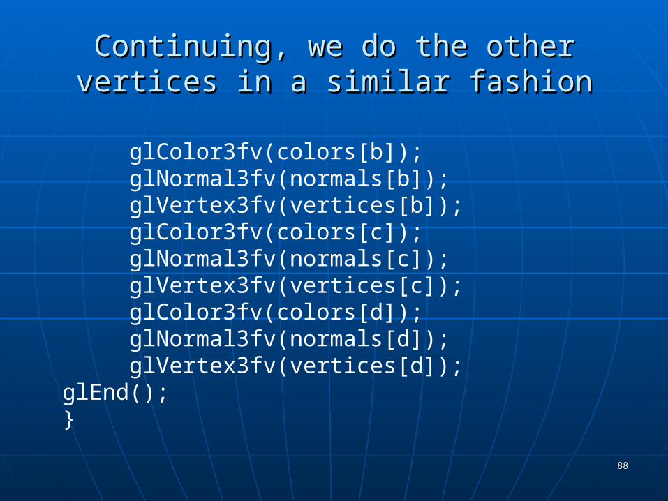
Continuing, we do the other vertices in a Continuing, we do the other vertices in a similar fashionsimilar fashion
glColor3fv(colors[b]);glNormal3fv(normals[b]);glVertex3fv(vertices[b]);glColor3fv(colors[c]);glNormal3fv(normals[c]);glVertex3fv(vertices[c]);glColor3fv(colors[d]);glNormal3fv(normals[d]);glVertex3fv(vertices[d]);
glEnd();}
8989
Modeling a Rotating CubeModeling a Rotating Cube
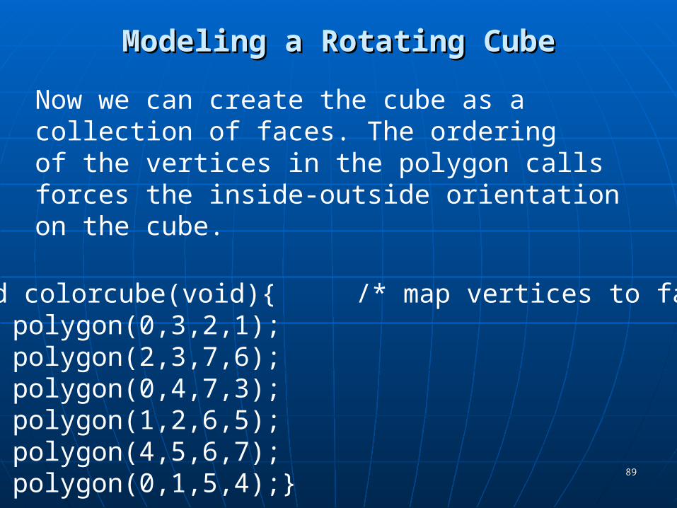
void colorcube(void){ /* map vertices to faces */polygon(0,3,2,1);polygon(2,3,7,6);polygon(0,4,7,3);polygon(1,2,6,5);polygon(4,5,6,7);polygon(0,1,5,4);}
Now we can create the cube as a collection of faces. The orderingof the vertices in the polygon calls forces the inside-outside orientation on the cube.
9090
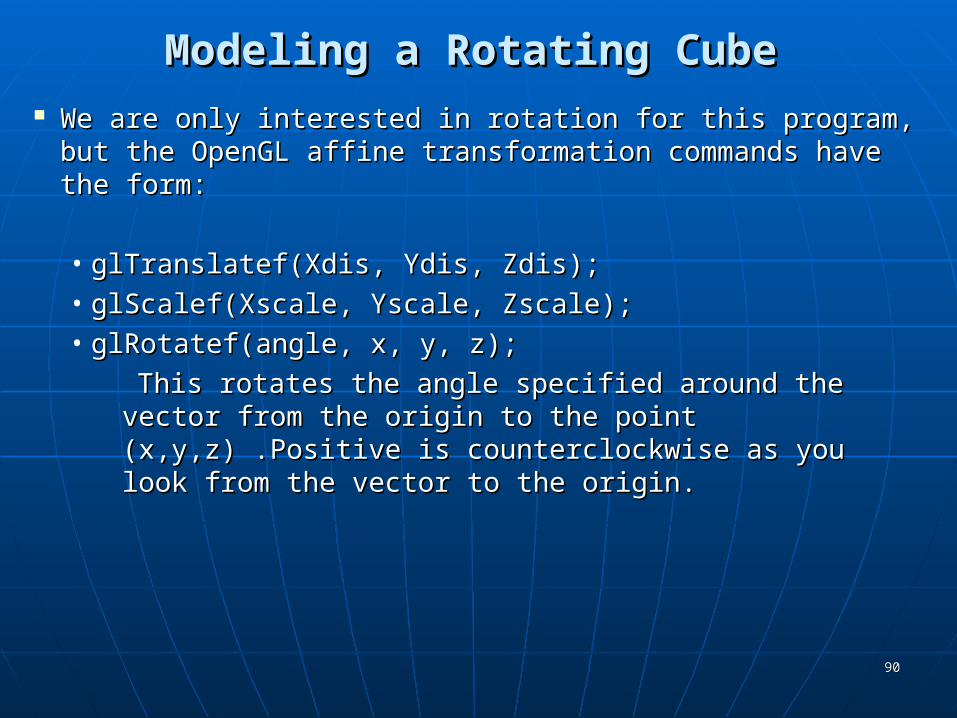
Modeling a Rotating CubeModeling a Rotating Cube We are only interested in rotation for this program, but the We are only interested in rotation for this program, but the
OpenGL affine transformation commands have the form:OpenGL affine transformation commands have the form:
• glTranslatef(Xdis, Ydis, Zdis);glTranslatef(Xdis, Ydis, Zdis);• glScalef(Xscale, Yscale, Zscale);glScalef(Xscale, Yscale, Zscale);• glRotatef(angle, x, y, z); glRotatef(angle, x, y, z);
This rotates the angle specified around the vector from This rotates the angle specified around the vector from the origin to the point (x,y,z) .Positive is the origin to the point (x,y,z) .Positive is counterclockwise as you look from the vector to the counterclockwise as you look from the vector to the origin.origin.
9191
So, why did we do all that translate-rotate-undo mess when this last command is so simple?
Because, OpenGL performs the calculation as we saw it specified, even though these commands look simple.

9292
Modeling a Rotating CubeModeling a Rotating Cube
Recall that OpenGL begins with the world frame and the camera frame the same.
Although you will write points as triples and vectors as triples (assuming the tail is at the origin), OpenGL will maintain them as homogeneous coordinates.
Frame changes are made by modifying the current transformation matrix (CTM), a 4 X 4 matrix in OpenGL that represents the cumulative effects of post-multiplying by frame change matrices.
Each affine transformation when invoked, forms the appropriate matrix and post-multiplies the CTM by that matrix ...
9393
Modeling a Rotating CubeModeling a Rotating Cube
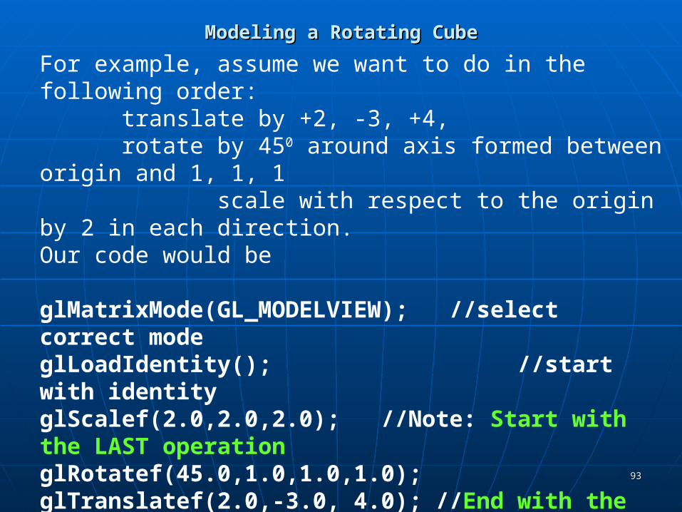
For example, assume we want to do in the following order: translate by +2, -3, +4, rotate by 450 around axis formed between origin and 1, 1, 1
scale with respect to the origin by 2 in each direction.Our code would be
glMatrixMode(GL_MODELVIEW); //select correct modeglLoadIdentity(); //start with identityglScalef(2.0,2.0,2.0); //Note: Start with the LAST operationglRotatef(45.0,1.0,1.0,1.0);glTranslatef(2.0,-3.0, 4.0); //End with the FIRST operation
The matrix formed will be C= S(2,2,2) R(45,1,1,1) T(2,-3,4)
Any vertex p specified after C is specified will be transformed toq = Cp

9494
MOVING MORE THAN ONE OBJECT TO MOVING MORE THAN ONE OBJECT TO DIFFERENT LOCATIONSDIFFERENT LOCATIONS
The last matrix loaded into the current transformation matrix determines what is applied to subsequent points.Example: Two objects are centered at the origin. Move one 10 units along the positive x-axis and one independently of the other 15 units along the negative y-axis.
Klutzy way:translate 10 units in xdraw 1st objecttranslate back to origintranslate 15 in ydraw 2nd object
Better way: Use a stackA stack is a data structure logically viewed as a list with a distinguished end called a top and several operations:
Push something- inserts something at the top into the stackPop- removes the top something from the stack and makes it the current transformation matrix

9595
MOVING MORE THAN ONE OBJECT TO MOVING MORE THAN ONE OBJECT TO DIFFERENT LOCATIONSDIFFERENT LOCATIONS
The type of code needed:
glPushMatrix(); //store old matrixglMatrixMode(GL_MODELVIEW);glLoadIdentity();glTranslatef(10.0,0.0,0.0);
//code to draw 1st object here//glPushMatrix(); optional- only if want to use later
glLoadIdentity();glTranslatef(0.0,15.0,0.0); //Can do more than one operation
//code to draw 2nd object hereglPopMatrix(); //May need more than one
//if you pushed the optional one//Now you are back to the old matrix
9696
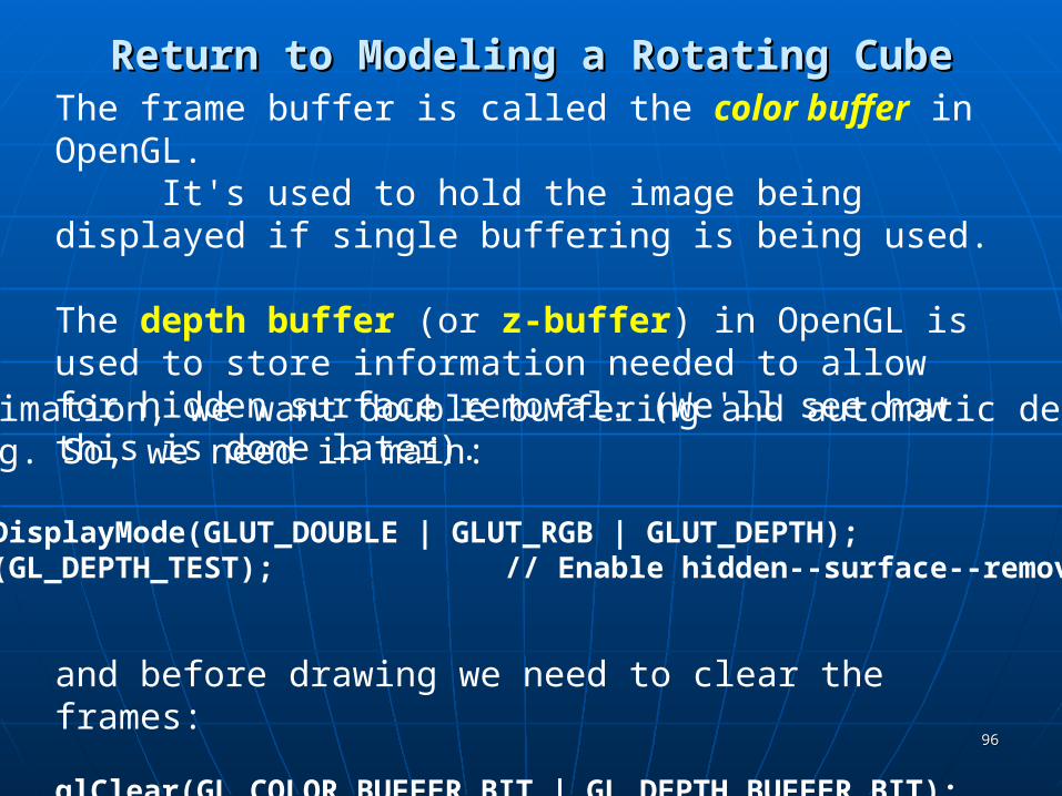
Return to Modeling a Rotating CubeReturn to Modeling a Rotating CubeThe frame buffer is called the color buffer in OpenGL.
It's used to hold the image being displayed if single buffering is being used.
The depth buffer (or z-buffer) in OpenGL is used to store information needed to allow for hidden surface removal. (We'll see how this is done later).
and before drawing we need to clear the frames:
glClear(GL_COLOR_BUFFER_BIT | GL_DEPTH_BUFFER_BIT);
With animation, we want double buffering and automatic depth handling. So, we need in main: glutInitDisplayMode(GLUT_DOUBLE | GLUT_RGB | GLUT_DEPTH);glEnable(GL_DEPTH_TEST); // Enable hidden--surface--removal

9797
Modeling a Rotating CubeModeling a Rotating Cube
Actual spin - at last!Mouse click chooses axis of rotation:
void mouse(int btn, int state, int x, int y){/* mouse callback, selects an axis about which to rotate */if(btn==GLUT_LEFT_BUTTON && state == GLUT_DOWN) axis = 0; //xif(btn==GLUT_MIDDLE_BUTTON && state == GLUT_DOWN) axis = 1; //y if(btn==GLUT_RIGHT_BUTTON && state == GLUT_DOWN) axis = 2; //z}
If you have only two buttons, you can change to keyboard control:void keys(unsigned char key, int x, int y)//Change so middle button is not needed{
if (key == 'x') axis = 0; // select x axisif (key == 'y') axis = 1; // select y axisif (key == 'z') axis = 2; // select z axisdisplay();
} //and don't forget to register keys
9898
Modeling a Rotating CubeModeling a Rotating Cube
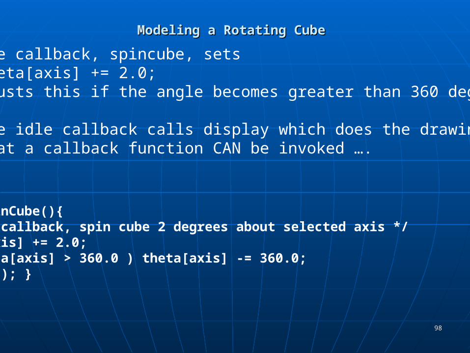
void spinCube(){/* Idle callback, spin cube 2 degrees about selected axis */theta[axis] += 2.0;if( theta[axis] > 360.0 ) theta[axis] -= 360.0;display(); }
The idle callback, spincube, setstheta[axis] += 2.0;
and adjusts this if the angle becomes greater than 360 degrees.
Then the idle callback calls display which does the drawing.Note that a callback function CAN be invoked ….

9999
Modeling a Rotating CubeModeling a Rotating Cube
All that remains is the reshape function which we have seen before:
void myReshape(int w, int h){ glViewport(0, 0, w, h); glMatrixMode(GL_PROJECTION); glLoadIdentity(); if (w <= h)
glOrtho(-2.0, 2.0, -2.0 * (GLfloat) h / (GLfloat) w, 2.0 * (GLfloat) h / (GLfloat) w, -10.0, 10.0);
else glOrtho(-2.0 * (GLfloat) w / (GLfloat) h,
2.0 * (GLfloat) w / (GLfloat) h, -2.0, 2.0, -10.0, 10.0); glMatrixMode(GL_MODELVIEW);
}
Note- this is still an orthographic projection which looks fine.