chapter 4 wireless lan - disco · pdf filechapter 4 wireless lan mobile ... bss): group of...
TRANSCRIPT
Chapter 4WIRELESS LAN
Mobile ComputingSummer 2004
DistributedComputing
Group

Distributed Computing Group MOBILE COMPUTING R. Wattenhofer 4/2
• Design goals• Characteristics
• IEEE 802.11– Architecture, Protocol– PHY, MAC – Cyclic Redundancy codes– Roaming, Security – a, b, g, etc.
• Bluetooth, RFID, etc.
Overview

Distributed Computing Group MOBILE COMPUTING R. Wattenhofer 4/3
Design goals
• Global, seamless operation• Low power consumption for battery use • No special permissions or licenses required• Robust transmission technology• Simplified spontaneous cooperation at meetings • Easy to use for everyone, simple management • Interoperable with wired networks • Security (no one should be able to read my data), privacy (no
one should be able to collect user profiles), safety (low radiation)• Transparency concerning applications and higher layer
protocols, but also location awareness if necessary

Distributed Computing Group MOBILE COMPUTING R. Wattenhofer 4/4
Characteristics
+ Very flexible (economical to scale)+ Ad-hoc networks without planning possible+ (Almost) no wiring difficulties (e.g. historic buildings, firewalls)+ More robust against disasters or users pulling a plug
– Low bandwidth compared to wired networks (10 vs. 100[0] Mbit/s)– Many proprietary solutions, especially for higher bit-rates,
standards take their time– Products have to follow many national restrictions if working
wireless, it takes a long time to establish global solutions (IMT-2000)
– Security– Economy

Distributed Computing Group MOBILE COMPUTING R. Wattenhofer 4/5
Infrastructure vs. ad-hoc networks
Infrastructurenetwork
Ad-hoc network
APAP
AP
wired network
AP: Access Point

Distributed Computing Group MOBILE COMPUTING R. Wattenhofer 4/6
Distribution System
Portal
802.x LAN
AccessPoint
802.11 LAN
BSS2
802.11 LAN
BSS1
AccessPoint
802.11 – Architecture of an infrastructure network
• Station (STA)– terminal with access mechanisms
to the wireless medium and radio contact to the access point
• Basic Service Set (BSS)– group of stations using the same
radio frequency• Access Point
– station integrated into the wireless LAN and the distribution system
• Portal– bridge to other (wired) networks
• Distribution System– interconnection network to form
one logical network (ESS: Extended Service Set) based on several BSS
STA1
STA2 STA3
ESS
Distributed Computing Group MOBILE COMPUTING R. Wattenhofer 4/7
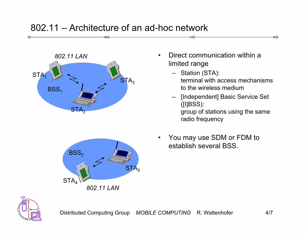
802.11 – Architecture of an ad-hoc network
• Direct communication within a limited range
– Station (STA):terminal with access mechanisms to the wireless medium
– [Independent] Basic Service Set ([I]BSS):group of stations using the same radio frequency
• You may use SDM or FDM to establish several BSS.
802.11 LAN
BSS2
802.11 LAN
BSS1
STA1
STA4
STA5
STA2
STA3

Distributed Computing Group MOBILE COMPUTING R. Wattenhofer 4/8
802.11 – Protocol architecture
mobile terminal
access point
server fixed terminal
application
TCP
802.11 PHY
802.11 MAC
IP
802.3 MAC
802.3 PHY
application
TCP
802.3 PHY
802.3 MAC
IP
802.11 MAC
802.11 PHY
LLC
infrastructure network
LLC LLC
Distributed Computing Group MOBILE COMPUTING R. Wattenhofer 4/9
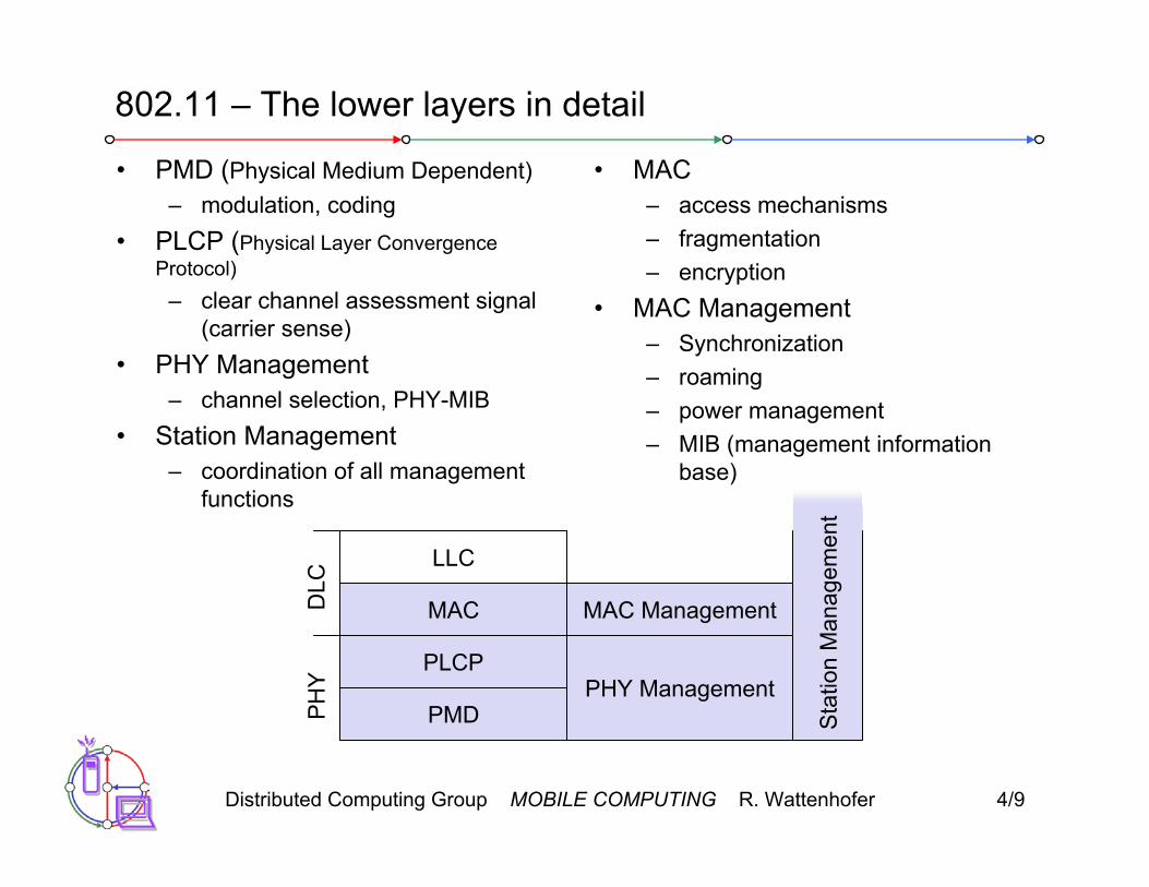
802.11 – The lower layers in detail
PMD
PLCP
MAC
LLC
MAC Management
PHY Management
PHY
DLC
Sta
tion
Man
agem
ent
• PMD (Physical Medium Dependent)– modulation, coding
• PLCP (Physical Layer ConvergenceProtocol)
– clear channel assessment signal (carrier sense)
• PHY Management– channel selection, PHY-MIB
• Station Management– coordination of all management
functions
• MAC– access mechanisms– fragmentation– encryption
• MAC Management– Synchronization– roaming– power management– MIB (management information
base)

Distributed Computing Group MOBILE COMPUTING R. Wattenhofer 4/10
Infrared vs. Radio transmission
Radio • typically using the license free
ISM band at 2.4 GHz + experience from wireless WAN
and mobile phones can be used + coverage of larger areas possible
(radio can penetrate walls, furniture etc.)
– very limited license free frequency bands
– shielding more difficult, interference with other electrical devices
• Examples: HIPERLAN, Bluetooth
Infrared • uses IR diodes, diffuse light,
multiple reflections (walls, furniture etc.)
+ simple, cheap, available in many mobile devices
+ no licenses needed+ simple shielding possible– interference by sunlight, heat
sources etc.– many things shield or absorb IR
light – low bandwidth• Example: IrDA (Infrared Data
Association) interface available everywhere

Distributed Computing Group MOBILE COMPUTING R. Wattenhofer 4/11
802.11 - Physical layer
• 3 versions: 2 radio (2.4 GHz), 1 IR (outdated):
• FHSS (Frequency Hopping Spread Spectrum)– spreading, despreading, signal strength, 1 Mbit/s– at least 2.5 frequency hops/s, two-level GFSK modulation
• DSSS (Direct Sequence Spread Spectrum)– DBPSK modulation for 1 Mbit/s (Differential Binary Phase Shift Keying),
DQPSK for 2 Mbit/s (Differential Quadrature PSK)– preamble and header of a frame is always transmitted with 1 Mbit/s, rest
of transmission 2 (or optionally 1) Mbit/s– chipping sequence: Barker code (+ – + + – + + + – – –)– max. radiated power 1 W (USA), 100 mW (EU), min. 1mW
• Infrared– 850-950 nm, diffuse light,10 m range– carrier detection, energy detection, synchronization

Distributed Computing Group MOBILE COMPUTING R. Wattenhofer 4/12
FHSS PHY packet format
synchronization SFD PLW PSF HEC payload
PLCP preamble PLCP header
80 16 12 4 16 variable bits
• Synchronization– synch with 010101... pattern
• SFD (Start Frame Delimiter)– 0000110010111101 start pattern
• PLW (PLCP_PDU Length Word)– length of payload incl. 32 bit CRC of payload, PLW < 4096
• PSF (PLCP Signaling Field)– data rate of payload (1 or 2 Mbit/s)
• HEC (Header Error Check)– CRC with x16+x12+x5+1

Distributed Computing Group MOBILE COMPUTING R. Wattenhofer 4/13
DSSS PHY packet format
synchronization SFD signal service HEC payload
PLCP preamble PLCP header
128 16 8 8 16 variable bits
length16
• Synchronization– synch., gain setting, energy detection, frequency offset compensation
• SFD (Start Frame Delimiter)– 1111001110100000
• Signal– data rate of the payload (0x0A: 1 Mbit/s DBPSK; 0x14: 2 Mbit/s DQPSK)
• Service (future use, 00: 802.11 compliant)• Length (length of the payload)• HEC (Header Error Check)
– protection of signal, service and length, x16+x12+x5+1
Distributed Computing Group MOBILE COMPUTING R. Wattenhofer 4/14
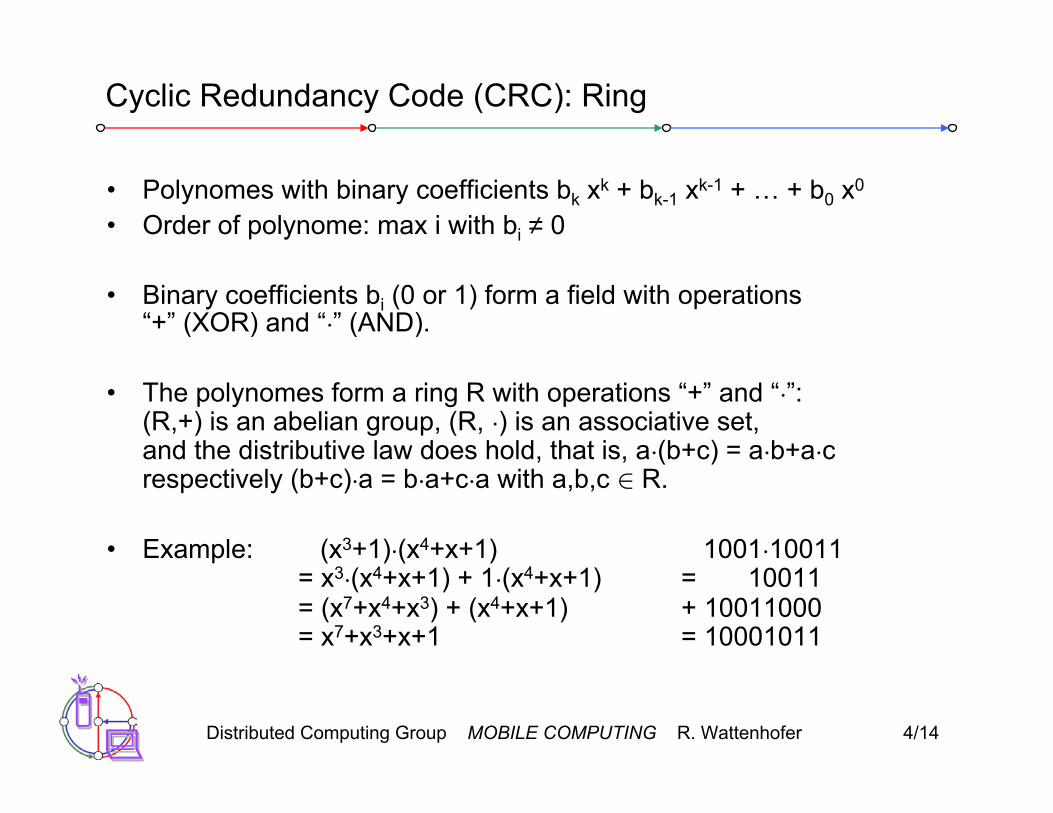
Cyclic Redundancy Code (CRC): Ring
• Polynomes with binary coefficients bk xk + bk-1 xk-1 + … + b0 x0
• Order of polynome: max i with bi ≠ 0
• Binary coefficients bi (0 or 1) form a field with operations “+” (XOR) and “·” (AND).
• The polynomes form a ring R with operations “+” and “·”:(R,+) is an abelian group, (R, ·) is an associative set,and the distributive law does hold, that is, a·(b+c) = a·b+a·crespectively (b+c)·a = b·a+c·a with a,b,c ∈ R.
• Example: (x3+1)·(x4+x+1) 1001·10011= x3·(x4+x+1) + 1·(x4+x+1) = 10011= (x7+x4+x3) + (x4+x+1) + 10011000 = x7+x3+x+1 = 10001011

Distributed Computing Group MOBILE COMPUTING R. Wattenhofer 4/15
Cyclic Redundancy Code (CRC): Division
• Generator polynome G(x) = x16+x12+x5+1• Let the whole header be polynome T(x) (order < 48)
• Idea: fill HEC (CRC) field such that T(x) mod G(x) = 0.• How to divide with polynomes? Example with G(x) = x2+1 (=101)
11101100 / 101 = 110110, Remainder 10100011111100010
• Idea: Fill CRC with remainder when dividing T(x) with HEC=00…0by G(x). Then calculating and testing CRC is the same operation.

Distributed Computing Group MOBILE COMPUTING R. Wattenhofer 4/16
Cyclic Redundancy Code (CRC): Division in Hardware
• Use cyclic shift register r registers, where r is the order of G(x)
• Example
G(x) = x3 + x2 + 1
Finally the remainder of the division is in the registers
+ + T(x)

Distributed Computing Group MOBILE COMPUTING R. Wattenhofer 4/17
Cyclic Redundancy Code (CRC): How to chose G(x)?
• Generator polynome G(x) = x16+x12+x5+1• Why does G(x) have this complicated form?
• Let E(x) be the transmission errors, that is T(x) = M(x) + E(x)• T(x) mod G(x) = (M(x) + E(x)) mod G(x)
= M(x) mod G(x) + E(x) mod G(x)• Since M(x) mod G(x) = 0 we can detect all transmission errors
as long as E(x) is not divisible by G(x) without remainder
• One can show that G(x) of order r can detect– all single bit errors as long as G(x) has 2 or more coefficients– all bursty errors (burst of length k is k-bit long 1xxxx1 string)
with k · r (note: needs G(x) to include the term 1)– Any error with probability 2-r

Distributed Computing Group MOBILE COMPUTING R. Wattenhofer 4/18
MAC layer: DFWMAC
• Traffic services– Asynchronous Data Service (mandatory)
• exchange of data packets based on “best-effort”• support of broadcast and multicast
– Time-Bounded Service (optional)• implemented using PCF (Point Coordination Function)
• Access methods– DFWMAC-DCF CSMA/CA (mandatory)
• collision avoidance via binary exponential back-off mechanism• minimum distance between consecutive packets• ACK packet for acknowledgements (not used for broadcasts)
– DFWMAC-DCF w/ RTS/CTS (optional)• avoids hidden terminal problem
– DFWMAC-PCF (optional)• access point polls terminals according to a list

Distributed Computing Group MOBILE COMPUTING R. Wattenhofer 4/19
MAC layer
• defined through different inter frame spaces• no guaranteed, hard priorities• SIFS (Short Inter Frame Spacing)
– highest priority, for ACK, CTS, polling response• PIFS (PCF IFS)
– medium priority, for time-bounded service using PCF• DIFS (DCF, Distributed Coordination Function IFS)
– lowest priority, for asynchronous data service
t
medium busy SIFSPIFSDIFSDIFS
next framecontention
direct access ifmedium is free ≥ DIFS

Distributed Computing Group MOBILE COMPUTING R. Wattenhofer 4/20
t
medium busy
DIFSDIFS
next frame
contention window(randomized back-offmechanism)
CSMA/CA
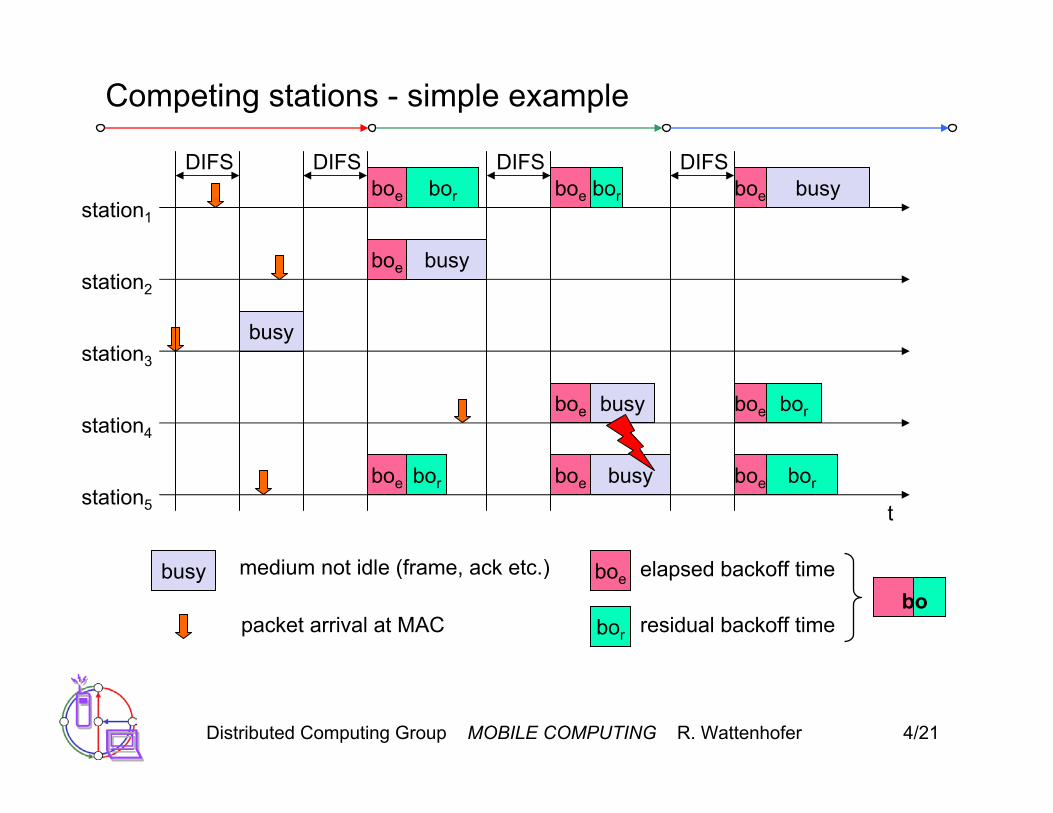
• station ready to send starts sensing the medium (Carrier Sense based on CCA, Clear Channel Assessment)
• if the medium is free for the duration of an Inter-Frame Space (IFS), the station can start sending (IFS depends on service type)
• if the medium is busy, the station has to wait for a free IFS, then the station must additionally wait a random back-off time (collision avoidance, multiple of slot-time)
• if another station occupies the medium during the back-off time of the station, the back-off timer stops (fairness)
slot timedirect access ifmedium is free ≥ DIFS
Distributed Computing Group MOBILE COMPUTING R. Wattenhofer 4/21
Competing stations - simple example
t
busy
boe
station1
station2
station3
station4
station5
packet arrival at MAC
DIFSboe
boe
boe
busy
elapsed backoff time
bor residual backoff time
busy medium not idle (frame, ack etc.)
bor
bor
DIFS
boe
boe
boe bor
DIFS
busy
busy
DIFSboe busy
boe
boe
bor
bor
bo

Distributed Computing Group MOBILE COMPUTING R. Wattenhofer 4/22
CSMA/CA 2
• Sending unicast packets– station has to wait for DIFS before sending data– receivers acknowledge at once (after waiting for SIFS) if the packet was
received correctly (CRC)– automatic retransmission of data packets in case of transmission errors
t
SIFS
DIFS
data
ACK
waiting time
otherstations
receiver
sender data
DIFS
contention
Distributed Computing Group MOBILE COMPUTING R. Wattenhofer 4/23
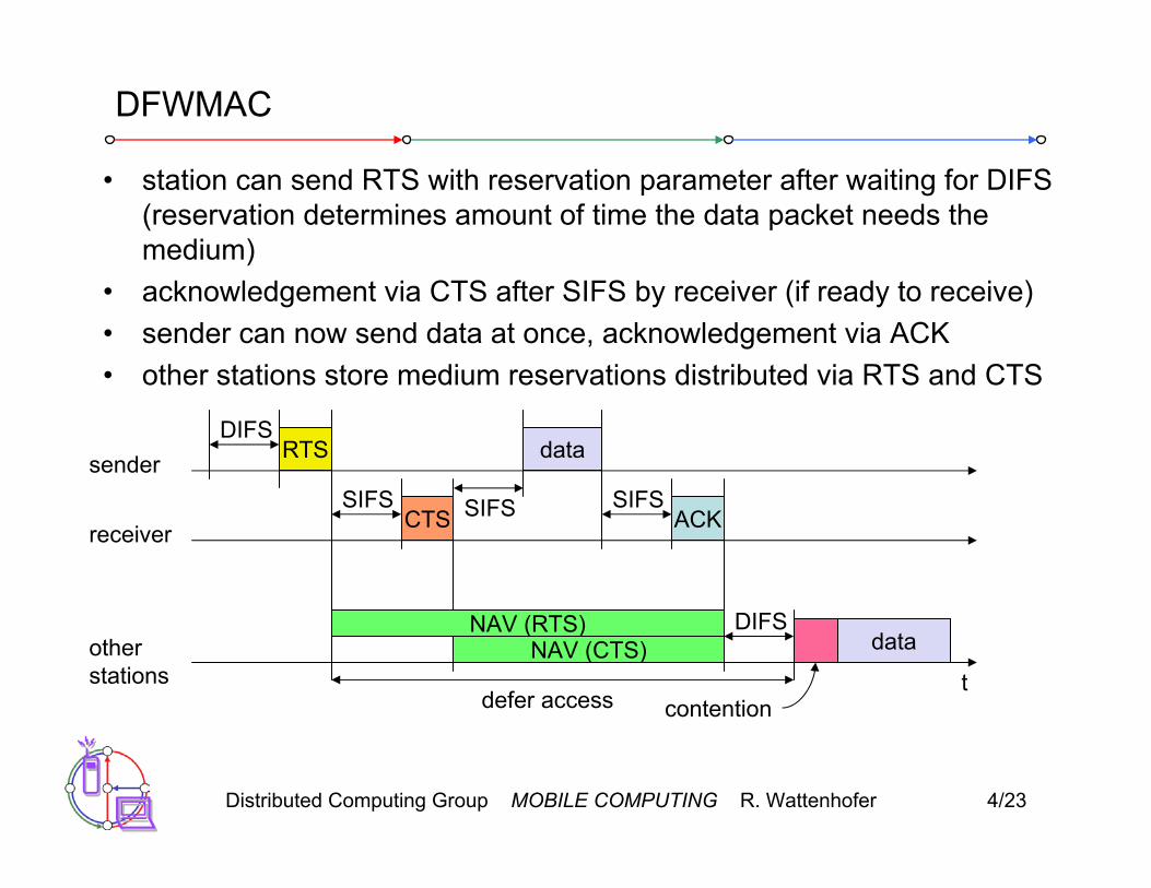
DFWMAC
• station can send RTS with reservation parameter after waiting for DIFS (reservation determines amount of time the data packet needs themedium)
• acknowledgement via CTS after SIFS by receiver (if ready to receive)• sender can now send data at once, acknowledgement via ACK• other stations store medium reservations distributed via RTS and CTS
t
SIFS
DIFS
data
ACK
defer access
otherstations
receiver
sender data
DIFS
contention
RTS
CTSSIFS SIFS
NAV (RTS)NAV (CTS)

Distributed Computing Group MOBILE COMPUTING R. Wattenhofer 4/24
Fragmentation
• If packet gets too long transmission error probability grows• A simple back of the envelope calculation determines
the optimal fragment size
t
SIFS
DIFS
data
ACK1
otherstations
receiver
sender frag1
DIFS
contention
RTS
CTSSIFS SIFS
NAV (RTS)NAV (CTS)
NAV (frag1)NAV (ACK1)
SIFSACK2
frag2
SIFS
Distributed Computing Group MOBILE COMPUTING R. Wattenhofer 4/25
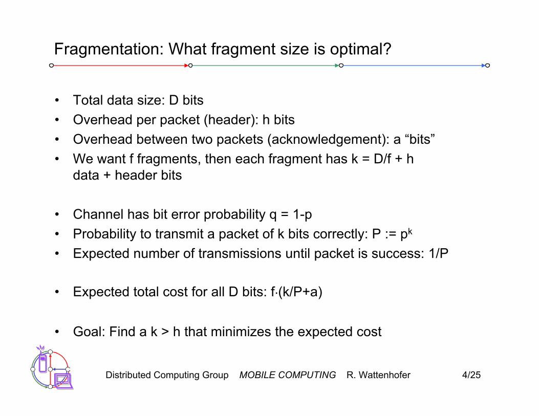
Fragmentation: What fragment size is optimal?
• Total data size: D bits• Overhead per packet (header): h bits• Overhead between two packets (acknowledgement): a “bits”• We want f fragments, then each fragment has k = D/f + h
data + header bits
• Channel has bit error probability q = 1-p• Probability to transmit a packet of k bits correctly: P := pk
• Expected number of transmissions until packet is success: 1/P
• Expected total cost for all D bits: f·(k/P+a)
• Goal: Find a k > h that minimizes the expected cost

Distributed Computing Group MOBILE COMPUTING R. Wattenhofer 4/26
Fragmentation: What fragment size is optimal?
• For the sake of a simplified analysis we assume a = O(h)
• If we further assume that a header can be transmitted with constant probability c, that is, ph = c.
• We choose k = 2h; Then clearly D = f·h, and therefore expected cost
• If already a header cannot be transmitted with high enough probability, then you might keep the message very small, for example k = h + 1/q

Distributed Computing Group MOBILE COMPUTING R. Wattenhofer 4/27
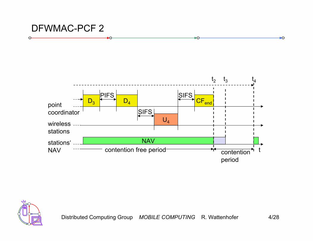
DFWMAC-PCF
• An access point can poll stations
PIFS
stations‘NAV
wirelessstations
point coordinator
D1
U1
SIFS
NAV
SIFSD2
U2
SIFS
SIFS
SuperFramet0
medium busy
t1
Distributed Computing Group MOBILE COMPUTING R. Wattenhofer 4/28
DFWMAC-PCF 2
tstations‘NAV
wirelessstations
point coordinator
D3
NAV
PIFSD4
U4
SIFS
SIFSCFend
contentionperiod
contention free period
t2 t3 t4
Distributed Computing Group MOBILE COMPUTING R. Wattenhofer 4/29
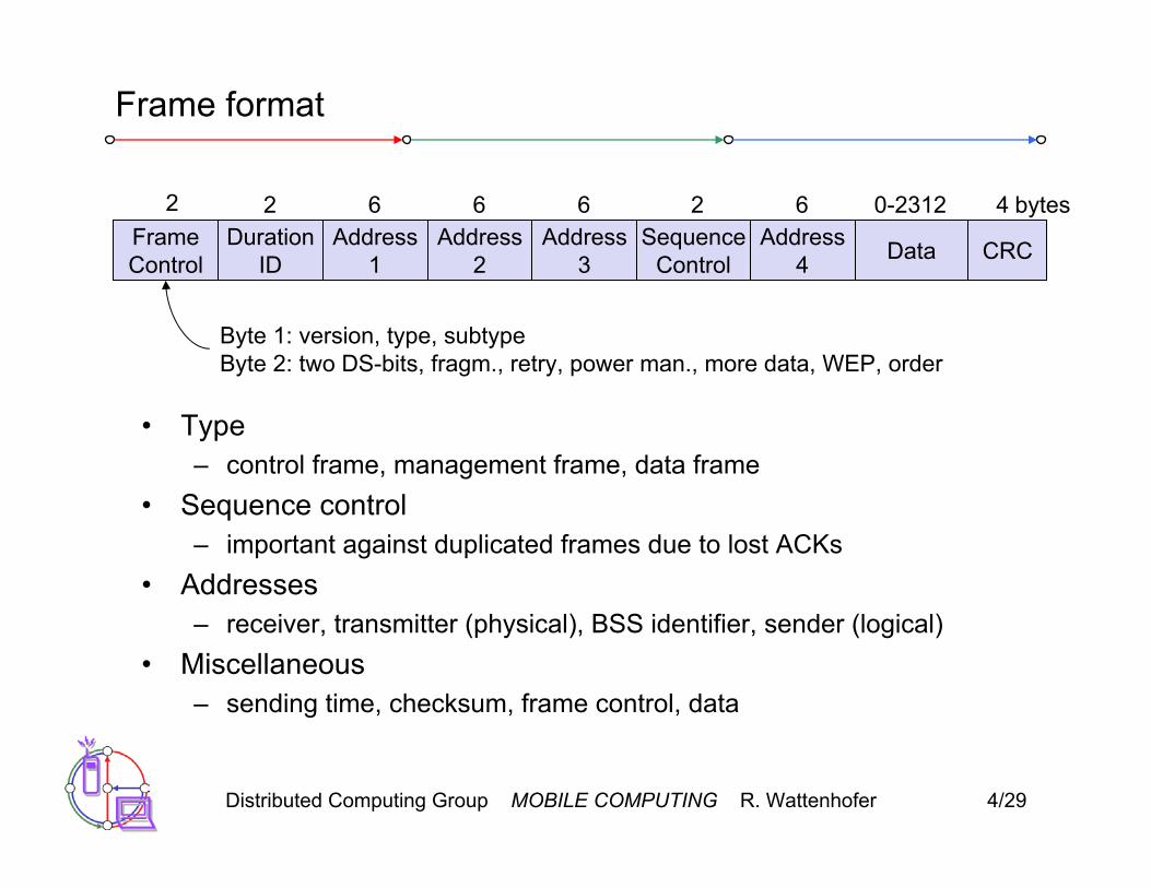
Frame format
• Type– control frame, management frame, data frame
• Sequence control– important against duplicated frames due to lost ACKs
• Addresses– receiver, transmitter (physical), BSS identifier, sender (logical)
• Miscellaneous– sending time, checksum, frame control, data
FrameControl
DurationID
Address1
Address2
Address3
SequenceControl
Address4 Data CRC
2 2 6 6 6 62 40-2312 bytes
Byte 1: version, type, subtypeByte 2: two DS-bits, fragm., retry, power man., more data, WEP, order

Distributed Computing Group MOBILE COMPUTING R. Wattenhofer 4/30
MAC address format
scenario to DS fromDS
address 1 address 2 address 3 address 4
ad-hoc network 0 0 DA SA BSSID -infrastructurenetwork, from AP
0 1 DA BSSID SA -
infrastructurenetwork, to AP
1 0 BSSID SA DA -
infrastructurenetwork, within DS
1 1 RA TA DA SA
DS: Distribution SystemAP: Access PointDA: Destination AddressSA: Source AddressBSSID: Basic Service Set IdentifierRA: Receiver AddressTA: Transmitter Address

Distributed Computing Group MOBILE COMPUTING R. Wattenhofer 4/31
Special Frames: ACK, RTS, CTS
• Acknowledgement
• Request To Send
• Clear To Send
FrameControl Duration Receiver
AddressTransmitter
Address CRC
2 2 6 6 4bytes
FrameControl Duration Receiver
Address CRC
2 2 6 4bytes
FrameControl Duration Receiver
Address CRC
2 2 6 4bytes
ACK
RTS
CTS

Distributed Computing Group MOBILE COMPUTING R. Wattenhofer 4/32
MAC management
• Synchronization– try to find a LAN, try to stay within a LAN– timer etc.
• Power management– sleep-mode without missing a message– periodic sleep, frame buffering, traffic measurements
• Association/Reassociation– integration into a LAN– roaming, i.e. change networks by changing access points – scanning, i.e. active search for a network
• MIB - Management Information Base– managing, read, write

Distributed Computing Group MOBILE COMPUTING R. Wattenhofer 4/33
Synchronization
• In an infrastructure network, the access point can send a beacon
beacon interval
tmedium
accesspoint
busy
B
busy busy busy
B B B
value of timestamp B beacon frame

Distributed Computing Group MOBILE COMPUTING R. Wattenhofer 4/34
Synchronization
• In an ad-hoc network, the beacon has to be sent by any station
tmedium
station1
busy
B1
beacon interval
busy busy busy
B1
value of the timestamp B beacon frame
station2B2 B2
backoff delay

Distributed Computing Group MOBILE COMPUTING R. Wattenhofer 4/35
Power management
• Idea: if not needed turn off the transceiver• States of a station: sleep and awake• Timing Synchronization Function (TSF)
– stations wake up at the same time• Infrastructure
– Traffic Indication Map (TIM)• list of unicast receivers transmitted by AP
– Delivery Traffic Indication Map (DTIM)• list of broadcast/multicast receivers transmitted by AP
• Ad-hoc– Ad-hoc Traffic Indication Map (ATIM)
• announcement of receivers by stations buffering frames• more complicated - no central AP• collision of ATIMs possible (scalability?)

Distributed Computing Group MOBILE COMPUTING R. Wattenhofer 4/36
Power saving with wake-up patterns (infrastructure)
TIM interval
t
medium
accesspoint
busy
D
busy busy busy
T T D
T TIM D DTIM
DTIM interval
BB
B broadcast/multicast
station
awake
p PS poll
p
d
d
d data transmissionto/from the station

Distributed Computing Group MOBILE COMPUTING R. Wattenhofer 4/37
Power saving with wake-up patterns (ad-hoc)
awake
A transmit ATIM D transmit datat
station1B1 B1
B beacon frame
station2B2 B2
random delay
A
a
D
d
ATIMwindow beacon interval
a acknowledge ATIM d acknowledge data

Distributed Computing Group MOBILE COMPUTING R. Wattenhofer 4/38
Roaming
• No or bad connection? Then perform:• Scanning
– scan the environment, i.e., listen into the medium for beacon signals or send probes into the medium and wait for an answer
• Reassociation Request– station sends a request to one or several AP(s)
• Reassociation Response– success: AP has answered, station can now participate– failure: continue scanning
• AP accepts reassociation request– signal the new station to the distribution system– the distribution system updates its data base (i.e., location information)– typically, the distribution system now informs the old AP so it can
release resources

Distributed Computing Group MOBILE COMPUTING R. Wattenhofer 4/39
WLAN: IEEE 802.11b
• Data rate– 1, 2, 5.5, 11 Mbit/s, depending on SNR – User data rate max. approx. 6 Mbit/s
• Transmission range– 300m outdoor, 30m indoor– Max. data rate <10m indoor
• Frequency– Free 2.4 GHz ISM-band
• Security– Limited, WEP insecure, SSID
• Cost– $50 adapter, $150 base station, dropping
• Availability– Many products, many vendors
Distributed Computing Group MOBILE COMPUTING R. Wattenhofer 4/40
WLAN: IEEE 802.11b
• Connection set-up time– Connectionless/always on
• Quality of Service– Typically best effort, no guarantees – unless polling is used, limited support in products
• Manageability– Limited (no automated key distribution, sym. encryption)
+ Advantages: many installed systems, lot of experience, availableworldwide, free ISM-band, many vendors, integrated in laptops, simple system
– Disadvantages: heavy interference on ISM-band, no service guarantees, slow relative speed only
Distributed Computing Group MOBILE COMPUTING R. Wattenhofer 4/41
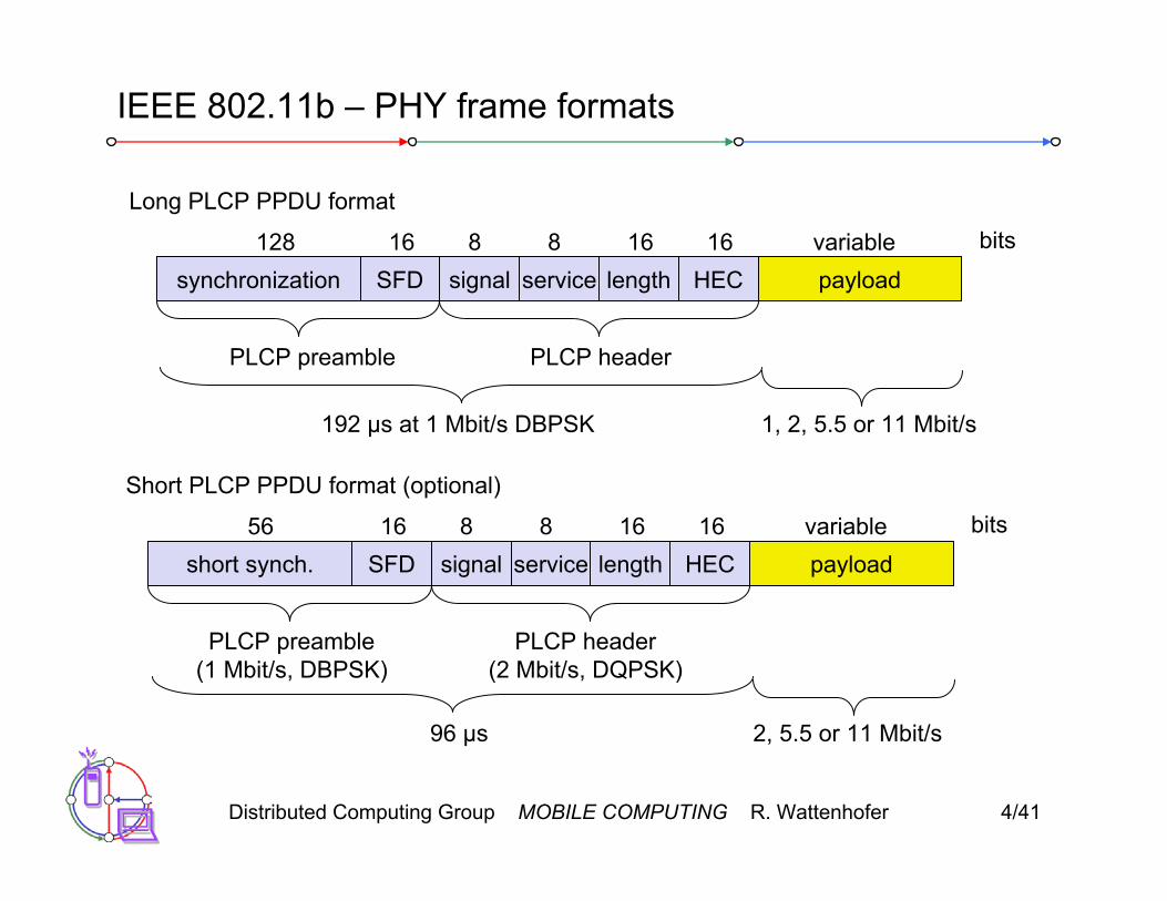
IEEE 802.11b – PHY frame formats
synchronization SFD signal service HEC payload
PLCP preamble PLCP header
128 16 8 8 16 variable bits
length16
192 µs at 1 Mbit/s DBPSK 1, 2, 5.5 or 11 Mbit/s
short synch. SFD signal service HEC payload
PLCP preamble(1 Mbit/s, DBPSK)
PLCP header(2 Mbit/s, DQPSK)
56 16 8 8 16 variable bits
length16
96 µs 2, 5.5 or 11 Mbit/s
Long PLCP PPDU format
Short PLCP PPDU format (optional)
Distributed Computing Group MOBILE COMPUTING R. Wattenhofer 4/42
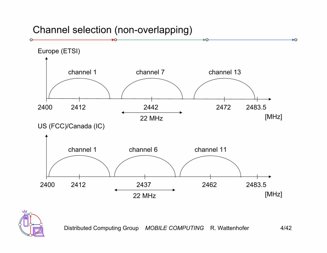
Channel selection (non-overlapping)
2400[MHz]
2412 2483.52442 2472
channel 1 channel 7 channel 13
Europe (ETSI)
US (FCC)/Canada (IC)
2400[MHz]
2412 2483.52437 2462
channel 1 channel 6 channel 11
22 MHz
22 MHz
Distributed Computing Group MOBILE COMPUTING R. Wattenhofer 4/43
WLAN: IEEE 802.11a
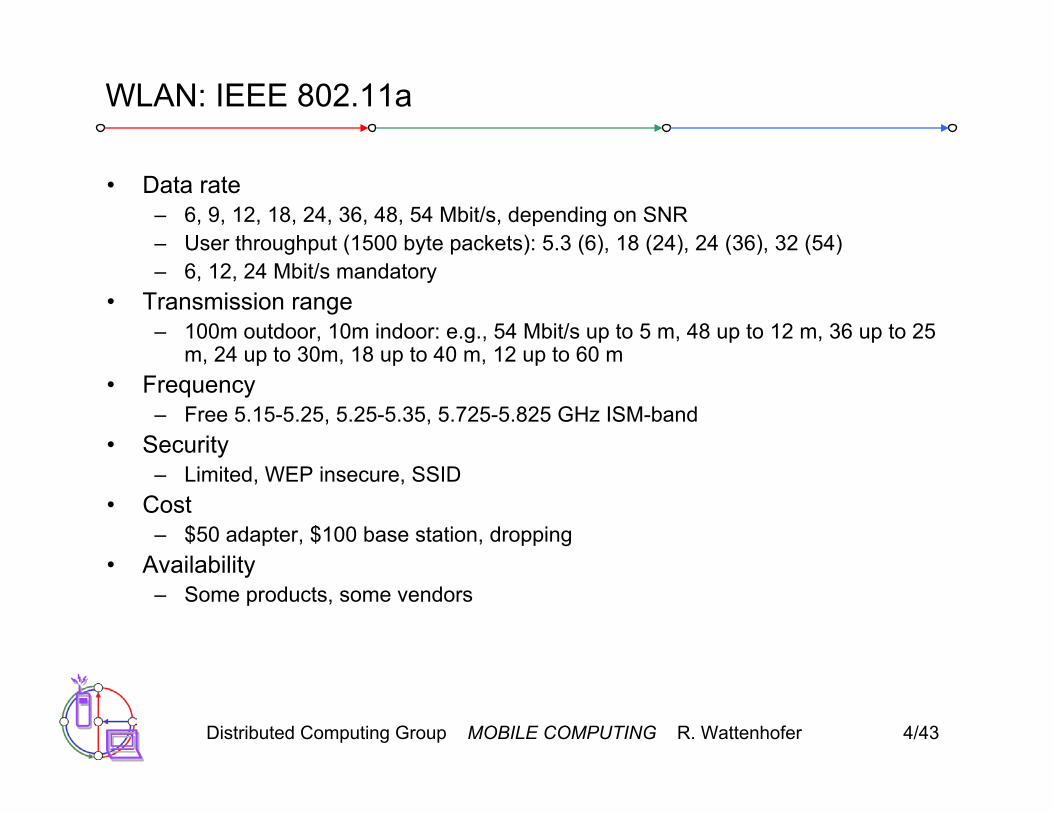
• Data rate– 6, 9, 12, 18, 24, 36, 48, 54 Mbit/s, depending on SNR– User throughput (1500 byte packets): 5.3 (6), 18 (24), 24 (36), 32 (54) – 6, 12, 24 Mbit/s mandatory
• Transmission range– 100m outdoor, 10m indoor: e.g., 54 Mbit/s up to 5 m, 48 up to 12 m, 36 up to 25
m, 24 up to 30m, 18 up to 40 m, 12 up to 60 m • Frequency
– Free 5.15-5.25, 5.25-5.35, 5.725-5.825 GHz ISM-band• Security
– Limited, WEP insecure, SSID• Cost
– $50 adapter, $100 base station, dropping• Availability
– Some products, some vendors

Distributed Computing Group MOBILE COMPUTING R. Wattenhofer 4/44
WLAN: IEEE 802.11a
• Connection set-up time– Connectionless/always on
• Quality of Service– Typically best effort, no guarantees (same as all 802.11 products)
• Manageability– Limited (no automated key distribution, sym. Encryption)
+ Advantages: fits into 802.x standards, free ISM-band, available, simple system, uses less crowded 5 GHz band
– Disadvantages: stronger shading due to higher frequency, no QoS
Distributed Computing Group MOBILE COMPUTING R. Wattenhofer 4/45
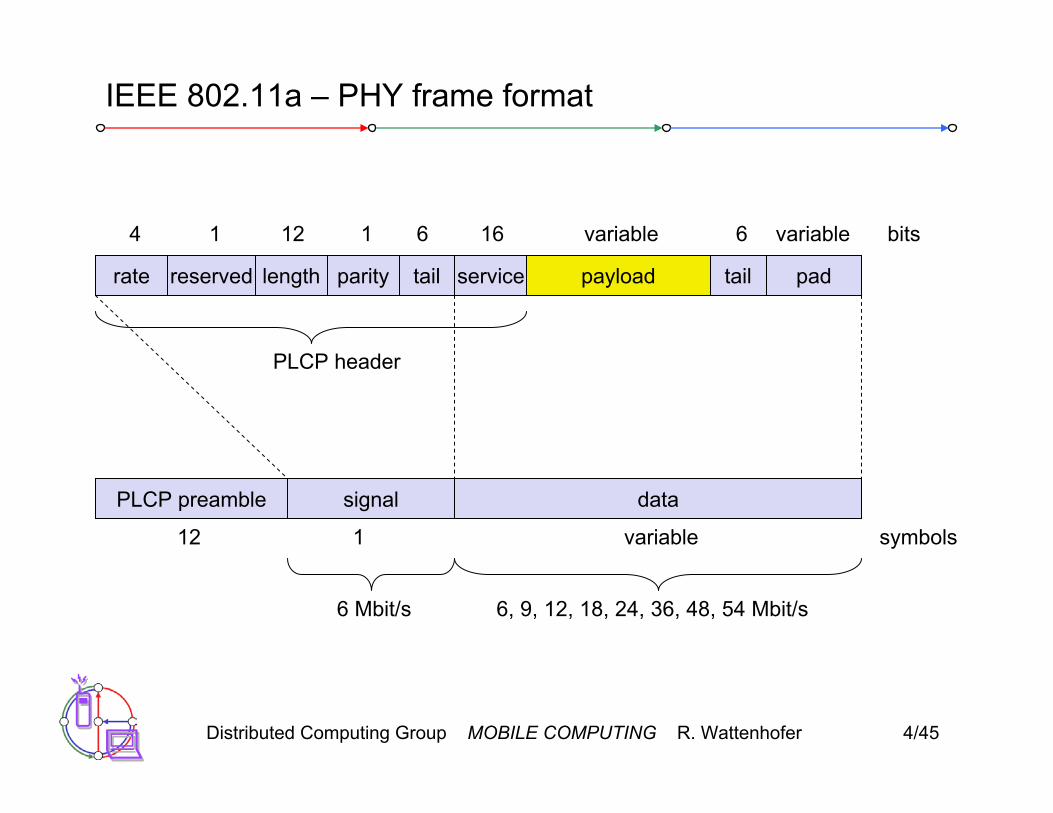
IEEE 802.11a – PHY frame format
rate service payload
variable bits
6 Mbit/s
PLCP preamble signal data
symbols12 1 variable
reserved length tailparity tail pad
616611214 variable
6, 9, 12, 18, 24, 36, 48, 54 Mbit/s
PLCP header

Distributed Computing Group MOBILE COMPUTING R. Wattenhofer 4/46
Operating channels for 802.11a / US U-NII
5150 [MHz]5180 53505200
36 44
16.6 MHz
center frequency = 5000 + 5*channel number [MHz]
channel40 48 52 56 60 64
149 153 157 161
5220 5240 5260 5280 5300 5320
5725 [MHz]5745 58255765
16.6 MHz
channel
5785 5805

Distributed Computing Group MOBILE COMPUTING R. Wattenhofer 4/47
OFDM in IEEE 802.11a (and HiperLAN2)
• OFDM with 52 used subcarriers (64 in total)• 48 data + 4 pilot (plus 12 virtual subcarriers)• 312.5 kHz spacing
subcarriernumber
1 7 21 26-26 -21 -7 -1channel center frequency
312.5 kHzpilot

Distributed Computing Group MOBILE COMPUTING R. Wattenhofer 4/48
WLAN: IEEE 802.11 – future developments (Late 2002)
• 802.11d: Regulatory Domain Update – completed• 802.11e: MAC Enhancements – QoS – ongoing
– Enhance the current 802.11 MAC to expand support for applications with Quality of Service requirements, and in the capabilities and efficiency of the protocol.
• 802.11f: Inter-Access Point Protocol – ongoing– Establish an Inter-Access Point Protocol for data exchange via the
distribution system.• 802.11g: Data Rates > 20 Mbit/s at 2.4 GHz; 54 Mbit/s, OFDM –
ongoing • 802.11h: Spectrum Managed 802.11a (DCS, TPC) – ongoing • 802.11i: Enhanced Security Mechanisms – ongoing
– Enhance the current 802.11 MAC to provide improvements in security. • Study Groups
– 5 GHz (harmonization ETSI/IEEE) – closed – Radio Resource Measurements – started– High Throughput – started

Distributed Computing Group MOBILE COMPUTING R. Wattenhofer 4/49
802.11 Security Today
• Existing security consists of two subsystems:– Wired Equivalent Privacy (WEP): A data encapsulation technique.– Shared Key Authentication: An authentication algorithm
• Goals: – Create the privacy achieved by a wired network– Simulate physical access control by denying access to unauthenticated
stations

Distributed Computing Group MOBILE COMPUTING R. Wattenhofer 4/50
WEP Encapsulation
Data ICV
DataIV = v ICV
Hdr Data
Hdr
RC4(v,k)
+
=
24 bits 32 bits
Distributed Computing Group MOBILE COMPUTING R. Wattenhofer 4/51
WEP protocol
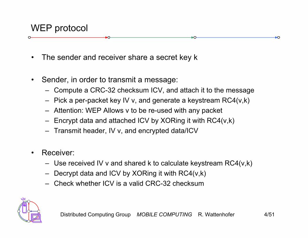
• The sender and receiver share a secret key k
• Sender, in order to transmit a message:– Compute a CRC-32 checksum ICV, and attach it to the message– Pick a per-packet key IV v, and generate a keystream RC4(v,k)– Attention: WEP Allows v to be re-used with any packet– Encrypt data and attached ICV by XORing it with RC4(v,k)– Transmit header, IV v, and encrypted data/ICV
• Receiver:– Use received IV v and shared k to calculate keystream RC4(v,k)– Decrypt data and ICV by XORing it with RC4(v,k)– Check whether ICV is a valid CRC-32 checksum

Distributed Computing Group MOBILE COMPUTING R. Wattenhofer 4/52
Vernam Ciphers
The WEP encryption algorithm RC4 is a Vernam Cipher:
Pseudo-random number
generatorEncryption
Key k
Plaintext data byte p
Random byte b
⊕ Ciphertext data byte c
Decryption works the same way: p = c ⊕ b

Distributed Computing Group MOBILE COMPUTING R. Wattenhofer 4/53
Properties of Vernam Ciphers
Thought experiment: what happens when p1 and p2 are encrypted under the same “random” byte b?
c1 = p1 ⊕ b c2 = p2 ⊕ b
Then:
Conclusion: it is a bad idea to encrypt any two bytes of data using the same byte output by a Vernam Cipher PRNG.
c1 ⊕ c2 = (p1 ⊕ b) ⊕ (p2 ⊕ b) = p1 ⊕ p2

Distributed Computing Group MOBILE COMPUTING R. Wattenhofer 4/54
How to read WEP encrypted traffic
• By the Birthday Paradox, probability Pn two packets will share same IV after n packets is P2 = 1/224 after two frames and Pn = Pn–1 + (n–1)(1–Pn–1)/224 for n > 2.
• 50% chance of a collision exists already after 4823 packets.
• Pattern recognition can disentangle the XOR’d recovered plaintext.• Recovered ICV can tell you when you’ve disentangled plaintext
correctly (or help to recover the plaintext in the first place).• Once you know a single RC4, you can inject your own packets
DataIV = v ICVHdr
24 bits 32 bits
Distributed Computing Group MOBILE COMPUTING R. Wattenhofer 4/55
How to read WEP encrypted traffic
• Ways to accelerate the process:
• Send spam into the network, then you already know the plaintext.• Get the victim to send e-mail to you, the AP creates the plaintext,
just for you.• For a given AP, everybody uses the same secret key k
• Very bad: Many 802.11 cards reset their IV (=v) counter to 0 every time they are activated, and simply increment it for each packet they transmit. In this case a spy knows the RC(v,k) for low v values in short time.
• Naturally a spy would use a decryption dictionary to store the already found RC4(v,k)… needs at most 224·1500 bytes = 24GBytes

Distributed Computing Group MOBILE COMPUTING R. Wattenhofer 4/56
Traffic Modification
Thought experiment: how hard is it to change a genuine packet’s data, so ICV won’t detect the change?
Represent an n-bit plaintext as an n-th degree binomial polynomial:
p = bnxn + bn–1xn–1 + … + b0x0
Then the plaintext with ICV can be represented as :
px32 + ICV(p) = bnxn+32 + bn–1xn+31 + … + b0x32 + ICV(p)
If the n+32 bit RC4 key stream used to encrypt the body is represented by the n+32nd degree polynomial r, then the encrypted message body is
px32 + ICV(p) + r
Distributed Computing Group MOBILE COMPUTING R. Wattenhofer 4/57
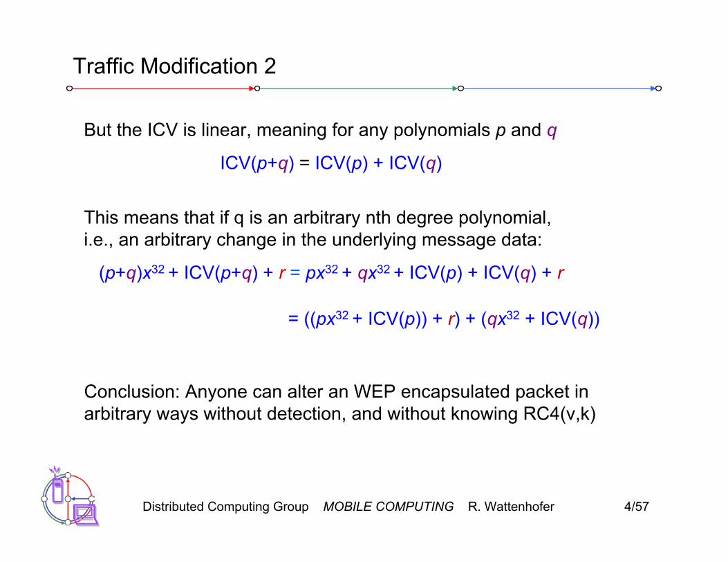
Traffic Modification 2
But the ICV is linear, meaning for any polynomials p and q
ICV(p+q) = ICV(p) + ICV(q)
Conclusion: Anyone can alter an WEP encapsulated packet in arbitrary ways without detection, and without knowing RC4(v,k)
This means that if q is an arbitrary nth degree polynomial, i.e., an arbitrary change in the underlying message data:
(p+q)x32 + ICV(p+q) + r = px32 + qx32 + ICV(p) + ICV(q) + r
= ((px32 + ICV(p)) + r) + (qx32 + ICV(q))

Distributed Computing Group MOBILE COMPUTING R. Wattenhofer 4/58
WEP Authentication
• Goal is that client joining the network really knows the shared key k• Protocol:
– Access point sends a challenge string to client– Client WEP-encrypts challenge, and sends result back to AP– If the challenge is encrypted correctly, AP accepts the client
• Client can spoof protocol the same way as injecting a message.• All a client needs is a valid RC4(v,k), for some v.

Distributed Computing Group MOBILE COMPUTING R. Wattenhofer 4/59
WEP message decryption revisited
• How can a client decrypt a specific packet with IV v for which the client does not have the RC4(v,k). (The first packet that uses v.)
• Idea: Use the access point (who knows k)
• Spoofing protocol (one of many possibilities):– Join the network (authentication spoofing)– Send a handcrafted message “encrypted” with key v to a destination
you control, for example a node outside the wireless LAN.– The AP will “decrypt” the message for you, and forward it to your
destination. When you XOR the “encrypted” with the “decrypted” message, you get the RC(v,k) for the v you wanted.
• There are some tedious details – but there are also other protocols

Distributed Computing Group MOBILE COMPUTING R. Wattenhofer 4/60
WEP lessons
• What could one do to improve WEP:– Use long IV’s that are used only once in the lifetime of a shared key k– Use a strong message authentication code (instead of a CRC code),
that does depend on the key and the IV.
• What you should do:
• Don’t trust WEP. Don’t trust it more than sending plain messagesover an Ethernet. However, WEP is usually seen as a good first deterrent against so-called “war drivers.”
• Put the wireless network outside your firewall• There are new proprietary security solutions such as LEAP.• Use other security mechanisms such as VPN, IPSec, ssh
Distributed Computing Group MOBILE COMPUTING R. Wattenhofer 4/61
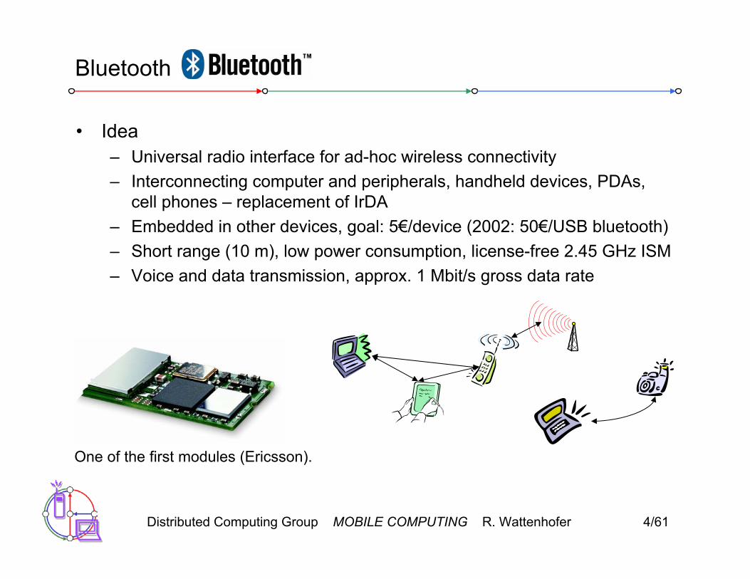
Bluetooth
• Idea– Universal radio interface for ad-hoc wireless connectivity– Interconnecting computer and peripherals, handheld devices, PDAs,
cell phones – replacement of IrDA– Embedded in other devices, goal: 5€/device (2002: 50€/USB bluetooth)– Short range (10 m), low power consumption, license-free 2.45 GHz ISM– Voice and data transmission, approx. 1 Mbit/s gross data rate
One of the first modules (Ericsson).

Distributed Computing Group MOBILE COMPUTING R. Wattenhofer 4/62
Bluetooth
• History– 1994: Ericsson (Mattison/Haartsen), “MC-link” project– Renaming of the project: Bluetooth according to Harald “Blåtand”
Gormsen [son of Gorm], King of Denmark in the 10th century– 1998: foundation of Bluetooth SIG, www.bluetooth.org– 1999: erection of a rune stone at Ercisson/Lund ;-)– 2001: first consumer products for mass market, spec. version 1.1
released
• Special Interest Group– Original founding members: Ericsson, Intel, IBM, Nokia, Toshiba– Added promoters: 3Com, Agere (was: Lucent), Microsoft, Motorola– > 2500 members– Common specification and certification of products

Distributed Computing Group MOBILE COMPUTING R. Wattenhofer 4/63
Characteristics
• 2.4 GHz ISM band, 79 RF channels, 1 MHz carrier spacing– Channel 0: 2402 MHz … channel 78: 2480 MHz– G-FSK modulation, 1-100 mW transmit power
• FHSS and TDD– Frequency hopping with 1600 hops/s– Hopping sequence in a pseudo random fashion, determined by a
master– Time division duplex for send/receive separation
• Voice link – SCO (Synchronous Connection Oriented)– FEC (forward error correction), no retransmission, 64 kbit/s duplex,
point-to-point, circuit switched• Data link – ACL (Asynchronous ConnectionLess)
– Asynchronous, fast acknowledge, point-to-multipoint, up to 433.9 kbit/s symmetric or 723.2/57.6 kbit/s asymmetric, packet switched
• Topology– Overlapping piconets (stars) forming a scatternet

Distributed Computing Group MOBILE COMPUTING R. Wattenhofer 4/64
Piconet
• Collection of devices connected in an ad hoc fashion
• One unit acts as master and the others as slaves for the lifetime of the piconet
• Master determines hopping pattern, slaves have to synchronize
• Each piconet has a unique hopping pattern
• Participation in a piconet = synchronization to hopping sequence
• Each piconet has one master and up to 7 simultaneous slaves (> 200 could be parked)
M=MasterS=Slave
P=ParkedSB=Standby
MS
P
SB
S
S
P
P
SB

Distributed Computing Group MOBILE COMPUTING R. Wattenhofer 4/65
Forming a piconet
• All devices in a piconet hop together– Master gives slaves its clock and device ID
• Hopping pattern: determined by device ID (48 bit, unique worldwide)• Phase in hopping pattern determined by clock
• Addressing– Active Member Address (AMA, 3 bit)– Parked Member Address (PMA, 8 bit)
SBSB
SB
SB
SB
SB
SB
SB
SB
MS
P
SB
S
S
P
P
SB

Distributed Computing Group MOBILE COMPUTING R. Wattenhofer 4/66
Scatternet
• Linking of multiple co-located piconets through the sharing of common master or slave devices– Devices can be slave in one piconet and master of another
• Communication between piconets– Devices jumping back and forth between the piconets
M=MasterS=SlaveP=ParkedSB=Standby
M
S
P
SB
S
S
P
P
SB
M
S
S
P
SB
Piconets(each with a capacity of < 1 Mbit/s)

Distributed Computing Group MOBILE COMPUTING R. Wattenhofer 4/67
Bluetooth protocol stack
Radio
Baseband
Link Manager
Control
HostControllerInterface
Logical Link Control and Adaptation Protocol (L2CAP)Audio
TCS BIN SDP
OBEX
vCal/vCard
IP
NW apps.
TCP/UDP
BNEP
RFCOMM (serial line interface)
AT modemcommands
telephony apps.audio apps. mgmnt. apps.
AT: attention sequenceOBEX: object exchangeTCS BIN: telephony control protocol specification – binaryBNEP: Bluetooth network encapsulation protocol
SDP: service discovery protocolRFCOMM: radio frequency comm.
PPP

Distributed Computing Group MOBILE COMPUTING R. Wattenhofer 4/68
S
Frequency selection during data transmission
fk
625 µs
fk+1 fk+2 fk+3 fk+4
fk+3 fk+4fk
fk
fk+5
fk+5
fk+1 fk+6
fk+6
fk+6
MM M M
M
M M
M M
t
t
t
S S
S S
S

Distributed Computing Group MOBILE COMPUTING R. Wattenhofer 4/69
Baseband
• Piconet/channel definition• Low-level packet definition
– Access code• Channel, device access, e.g., derived from master
– Packet header• 1/3-FEC, active member address (broadcast + 7 slaves), link type,
alternating bit ARQ/SEQ, checksum
access code packet header payload68(72) 54 0-2745 bits
AM address type flow ARQN SEQN HEC3 4 1 1 1 8 bits
preamble sync. (trailer)
4 64 (4)

Distributed Computing Group MOBILE COMPUTING R. Wattenhofer 4/70
SCO payload types
payload (30)
audio (30)
audio (10)
audio (10)
HV3
HV2
HV1
DV
FEC (20)
audio (20) FEC (10)
header (1) payload (0-9) 2/3 FEC CRC (2)
(bytes)

Distributed Computing Group MOBILE COMPUTING R. Wattenhofer 4/71
ACL Payload types
payload (0-343)
header (1/2) payload (0-339) CRC (2)
header (1) payload (0-17) 2/3 FEC
header (1) payload (0-27)
header (2) payload (0-121) 2/3 FEC
header (2) payload (0-183)
header (2) payload (0-224) 2/3 FEC
header (2) payload (0-339)DH5
DM5
DH3
DM3
DH1
DM1
header (1) payload (0-29)AUX1
CRC (2)
CRC (2)
CRC (2)
CRC (2)
CRC (2)
CRC (2)
(bytes)
Distributed Computing Group MOBILE COMPUTING R. Wattenhofer 4/72
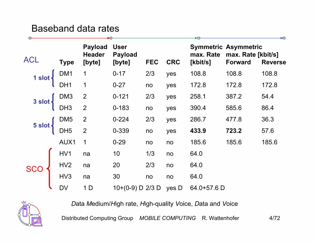
Baseband data rates
Payload User Symmetric AsymmetricHeader Payload max. Rate max. Rate [kbit/s]
Type [byte] [byte] FEC CRC [kbit/s] Forward Reverse
DM1 1 0-17 2/3 yes 108.8 108.8 108.8
DH1 1 0-27 no yes 172.8 172.8 172.8
DM3 2 0-121 2/3 yes 258.1 387.2 54.4
DH3 2 0-183 no yes 390.4 585.6 86.4
DM5 2 0-224 2/3 yes 286.7 477.8 36.3
DH5 2 0-339 no yes 433.9 723.2 57.6
AUX1 1 0-29 no no 185.6 185.6 185.6
HV1 na 10 1/3 no 64.0
HV2 na 20 2/3 no 64.0
HV3 na 30 no no 64.0
DV 1 D 10+(0-9) D 2/3 D yes D 64.0+57.6 D
ACL
1 slot
3 slot
5 slot
SCO
Data Medium/High rate, High-quality Voice, Data and Voice

Distributed Computing Group MOBILE COMPUTING R. Wattenhofer 4/73
Baseband link types
• Polling-based TDD packet transmission– 625µs slots, master polls slaves
• SCO (Synchronous Connection Oriented) – Voice – Periodic single slot packet assignment, 64 kbit/s full-duplex, point-to-point
• ACL (Asynchronous ConnectionLess) – Data – Variable packet size (1,3,5 slots), asymmetric bandwidth, point-to-multipoint
MASTER
SLAVE 1
SLAVE 2
f6f0
f1 f7
f12
f13 f19
f18
SCO SCO SCO SCOACL
f5 f21
f4 f20
ACLACLf8
f9
f17
f14
ACL

Distributed Computing Group MOBILE COMPUTING R. Wattenhofer 4/74
Robustness
• Slow frequency hopping with hopping patterns determined by a master– Protection from interference on certain frequencies– Separation from other piconets (FH-CDMA)
• Retransmission– ACL only, very fast
• Forward Error Correction: SCO and ACL
MASTER
SLAVE 1
SLAVE 2
A C C HF
G G
B D E
NAK ACK
Error in payload(not header!)

Distributed Computing Group MOBILE COMPUTING R. Wattenhofer 4/75
Baseband States of a Bluetooth Device
standby
inquiry page
connectedAMA
transmitAMA
parkPMA
holdAMA
sniffAMA
unconnected
connecting
active
low power
Standby: do nothingInquire: search for other devicesPage: connect to a specific deviceConnected: participate in a piconet
detach
Park: release AMA, get PMA Sniff: listen periodically, not each slotHold: stop ACL, SCO still possible, possibly
participate in another piconet

Distributed Computing Group MOBILE COMPUTING R. Wattenhofer 4/76
Example: Power consumption/CSR BlueCore2• Typical Average Current Consumption (1)• VDD=1.8V Temperature = 20°C• Mode • SCO connection HV3 (1s interval Sniff Mode) (Slave) 26.0 mA• SCO connection HV3 (1s interval Sniff Mode) (Master) 26.0 mA• SCO connection HV1 (Slave) 53.0 mA• SCO connection HV1 (Master) 53.0 mA• ACL data transfer 115.2kbps UART (Master) 15.5 mA• ACL data transfer 720kbps USB (Slave) 53.0 mA• ACL data transfer 720kbps USB (Master) 53.0 mA• ACL connection, Sniff Mode 40ms interval, 38.4kbps UART 4.0 mA• ACL connection, Sniff Mode 1.28s interval, 38.4kbps UART 0.5 mA• Parked Slave, 1.28s beacon interval, 38.4kbps UART 0.6 mA• Standby Mode (Connected to host, no RF activity) 47.0 µA• Deep Sleep Mode(2) 20.0 µA• Notes:• (1) Current consumption is the sum of both BC212015A and the flash.• (2) Current consumption is for the BC212015A device only.• (More: www.csr.com )

Distributed Computing Group MOBILE COMPUTING R. Wattenhofer 4/77
L2CAP - Logical Link Control and Adaptation Protocol
• Simple data link protocol on top of baseband• Connection oriented, connectionless, and signaling channels• Protocol multiplexing
– RFCOMM, SDP, telephony control• Segmentation & reassembly
– Up to 64kbyte user data, 16 bit CRC used from baseband• QoS flow specification per channel
– Follows RFC 1363, specifies delay, jitter, bursts, bandwidth• Group abstraction
– Create/close group, add/remove member

Distributed Computing Group MOBILE COMPUTING R. Wattenhofer 4/78
L2CAP logical channels
baseband
L2CAP
baseband
L2CAP
baseband
L2CAP
Slave SlaveMaster
ACL
2 d 1 d d 1 1 d 21
signalling connectionless connection-oriented
d d d

Distributed Computing Group MOBILE COMPUTING R. Wattenhofer 4/79
L2CAP packet formats
length2 bytes
CID=22
PSM≥2
payload0-65533
length2 bytes
CID2
payload0-65535
length2 bytes
CID=12
One or more commands
Connectionless PDU
Connection-oriented PDU
Signaling command PDU
code ID length data1 1 2 ≥0
Distributed Computing Group MOBILE COMPUTING R. Wattenhofer 4/80
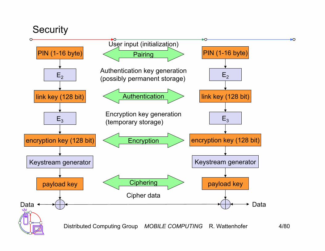
Security
E3
E2
link key (128 bit)
encryption key (128 bit)
payload key
Keystream generator
Data DataCipher data
Authentication key generation(possibly permanent storage)
Encryption key generation(temporary storage)
PIN (1-16 byte)User input (initialization)
Pairing
Authentication
Encryption
Ciphering
E3
E2
link key (128 bit)
encryption key (128 bit)
payload key
Keystream generator
PIN (1-16 byte)

Distributed Computing Group MOBILE COMPUTING R. Wattenhofer 4/81
SDP – Service Discovery Protocol
• Inquiry/response protocol for discovering services– Searching for and browsing services in radio proximity– Adapted to the highly dynamic environment– Can be complemented by others like SLP, Jini, Salutation, …– Defines discovery only, not the usage of services– Caching of discovered services– Gradual discovery
• Service record format– Information about services provided by attributes– Attributes are composed of an 16 bit ID (name) and a value– values may be derived from 128 bit Universally Unique Identifiers
(UUID)

Distributed Computing Group MOBILE COMPUTING R. Wattenhofer 4/82
Additional protocols to support legacy protocols/apps
• RFCOMM– Emulation of a serial port (supports a large base of legacy applications)– Allows multiple ports over a single physical channel
• Telephony Control Protocol Specification (TCS)– Call control (setup, release)– Group management
• OBEX– Exchange of objects, IrDA replacement
• WAP– Interacting with applications on cellular phones
Distributed Computing Group MOBILE COMPUTING R. Wattenhofer 4/83
Profiles
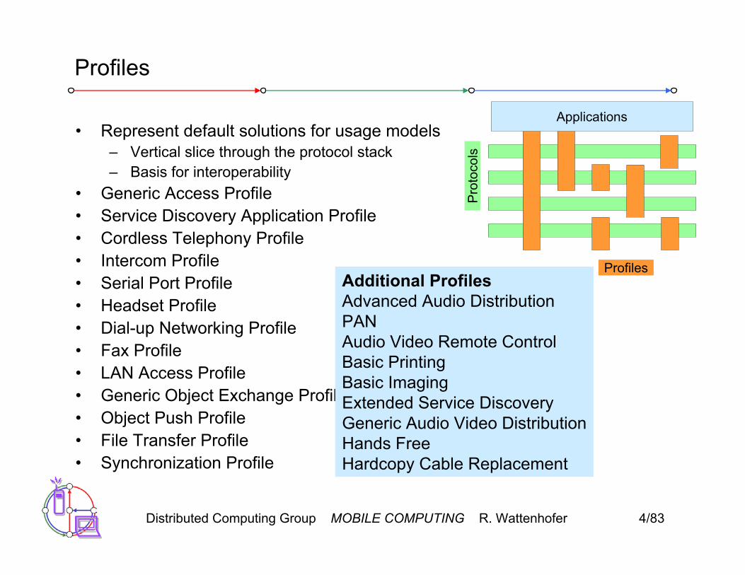
• Represent default solutions for usage models– Vertical slice through the protocol stack– Basis for interoperability
• Generic Access Profile• Service Discovery Application Profile• Cordless Telephony Profile• Intercom Profile• Serial Port Profile• Headset Profile• Dial-up Networking Profile• Fax Profile• LAN Access Profile• Generic Object Exchange Profile• Object Push Profile• File Transfer Profile• Synchronization Profile
Additional ProfilesAdvanced Audio DistributionPANAudio Video Remote ControlBasic PrintingBasic ImagingExtended Service DiscoveryGeneric Audio Video DistributionHands FreeHardcopy Cable Replacement
Profiles
Pro
toco
ls
Applications

Distributed Computing Group MOBILE COMPUTING R. Wattenhofer 4/84
WPAN: IEEE 802.15-1 – Bluetooth
• Data rate– Synchronous, connection-oriented: 64 kbit/s– Asynchronous, connectionless
• 433.9 kbit/s symmetric• 723.2 / 57.6 kbit/s asymmetric
• Transmission range– POS (Personal Operating Space) up to 10 m– with special transceivers up to 100 m
• Frequency– Free 2.4 GHz ISM-band
• Security– Challenge/response (SAFER+), hopping sequence
• Cost– 50€ adapter, drop to 5€ if integrated
• Availability– Integrated into some products, several vendors

Distributed Computing Group MOBILE COMPUTING R. Wattenhofer 4/85
WPAN: IEEE 802.15-1 – Bluetooth
• Connection set-up time– Depends on power-mode– Max. 2.56s, avg. 0.64s
• Quality of Service– Guarantees, ARQ/FEC
• Manageability– Public/private keys needed, key management not specified, simple
system integration+ Advantages: already integrated into several products, available
worldwide, free ISM-band, several vendors, simple system, simple ad-hoc networking, peer to peer, scatternets
– Disadvantages: interference on ISM-band, limited range, max. 8 devices/network&master, high set-up latency

Distributed Computing Group MOBILE COMPUTING R. Wattenhofer 4/86
WPAN: IEEE 802.15 – future developments
• 802.15-2: Coexistence– Coexistence of Wireless Personal Area Networks (802.15) and Wireless
Local Area Networks (802.11), quantify the mutual interference
• 802.15-3: High-Rate– Standard for high-rate (20Mbit/s or greater) WPANs, while still low-
power/low-cost – Data Rates: 11, 22, 33, 44, 55 Mbit/s – Quality of Service isochronous protocol – Ad-hoc peer-to-peer networking – Security – Low power consumption – Low cost – Designed to meet the demanding requirements of portable consumer
imaging and multimedia applications

Distributed Computing Group MOBILE COMPUTING R. Wattenhofer 4/87
WPAN: IEEE 802.15 – future developments
• 802.15-4: Low-Rate, Very Low-Power– Low data rate solution with multi-month to multi-year battery life and
very low complexity– Potential applications are sensors, interactive toys, smart badges,
remote controls, and home automation– Data rates of 20-250 kbit/s, latency down to 15 ms– Master-Slave or Peer-to-Peer operation– Support for critical latency devices, such as joysticks– CSMA/CA channel access (data centric), slotted (beacon) or unslotted– Automatic network establishment by the PAN coordinator– Dynamic device addressing, flexible addressing format– Fully handshaked protocol for transfer reliability– Power management to ensure low power consumption– 16 channels in the 2.4 GHz ISM band, 10 channels in the 915 MHz US
ISM band and one channel in the European 868 MHz band

Distributed Computing Group MOBILE COMPUTING R. Wattenhofer 4/88
WLAN: Home RF
• Data rate– 0.8, 1.6, 5, 10 Mbit/s
• Transmission range– 300m outdoor, 30m indoor
• Frequency– 2.4 GHz ISM
• Security– Strong encryption, no open
access• Cost
– Adapter $50, base station $100• Availability
– Several products from different vendors
• Connection set-up time– 10 ms bounded latency
• Quality of Service– Up to 8 streams A/V, up to 8 voice
streams, priorities, best-effort• Manageability
– Like DECT & 802-LANs+ Advantages: extended QoS
support, host/client and peer/peer, power saving, security
– Disadvantages: future uncertain due to DECT-only devices plus 802.11a/b for data
Distributed Computing Group MOBILE COMPUTING R. Wattenhofer 4/89
RF Controllers – ISM bands
• Data rate– Typ. up to 115 kbit/s (serial
interface)• Transmission range
– 5-100 m, depending on power (typ. 10-500 mW)
• Frequency– Typ. 27 (EU, US), 315 (US), 418
(EU), 426 (Japan), 433 (EU), 868 (EU), 915 (US) MHz (depending on regulations)
• Security– Some products with added
processors• Cost
– Cheap: $10-$50• Availability
– Many products, many vendors
• Connection set-up time– N/A
• Quality of Service– none
• Manageability– Very simple, same as serial
interface• Advantages: very low cost, large
experience, high volume available– Disadvantages: no QoS, crowded
ISM bands (particularly 27 and 433 MHz), typ. no Medium Access Control, 418 MHz experiences interference with TETRA

Distributed Computing Group MOBILE COMPUTING R. Wattenhofer 4/90
Broadband network types
• Common characteristics– ATM QoS (CBR, VBR, UBR, ABR)
• HIPERLAN/2– short range (< 200 m), indoor/campus, 25 Mbit/s user data rate– access to telecommunication systems, multimedia applications, mobility
(<10 m/s)• HIPERACCESS
– wider range (< 5 km), outdoor, 25 Mbit/s user data rate– fixed radio links to customers (“last mile”), alternative to xDSL or cable
modem, quick installation– Several (proprietary) products exist with 155 Mbit/s plus QoS
• HIPERLINK – currently no activities– intermediate link, 155 Mbit/s– connection of HIPERLAN access points or connection between
HIPERACCESS nodes

Distributed Computing Group MOBILE COMPUTING R. Wattenhofer 4/91
RFID – Radio Frequency Identification
• Function– Standard: In response to a radio interrogation signal from a reader
(base station) the RFID tags transmit their ID– Enhanced: additionally data can be sent to the tags, different media
access schemes (collision avoidance)• Features
– No line-of sight required (compared to, e.g., laser scanners)– RFID tags withstand difficult environmental conditions (sunlight, cold,
frost, dirt etc.)– Products available with read/write memory, smart-card capabilities
• Categories– Passive RFID: operating power comes from the reader over the air
which is feasible up to distances of 3 m, low price (1€)– Active RFID: battery powered, distances up to 100 m
Distributed Computing Group MOBILE COMPUTING R. Wattenhofer 4/92
RFID – Radio Frequency Identification
• Data rate– Transmission of ID only (e.g., 48 bit,
64kbit, 1 Mbit)– 9.6 – 115 kbit/s
• Transmission range– Passive: up to 3 m– Active: up to 30-100 m– Simultaneous detection of up to, e.g.,
256 tags, scanning of, e.g., 40 tags/s• Frequency
– 125 kHz, 13.56 MHz, 433 MHz, 2.4 GHz, 5.8 GHz and many others
• Security– Application dependent, typ. no crypt.
on RFID device• Cost
– Very cheap tags, down to $1 (passive)• Availability
– Many products, many vendors
• Connection set-up time– Depends on product/medium access
scheme (typ. 2 ms per device)• Quality of Service
– none• Manageability
– Very simple, same as serial interface+ Advantages: extremely low cost, large
experience, high volume available, no power for passive RFIDs needed, large variety of products, relative speeds up to 300 km/h, broad temp. range
– Disadvantages: no QoS, simple denial of service, crowded ISM bands, typ. one-way (activation/ transmission of ID)
Distributed Computing Group MOBILE COMPUTING R. Wattenhofer 4/93
RFID – Radio Frequency Identification
• Applications– Total asset visibility: tracking of goods during manufacturing,
localization of pallets, goods etc.– Loyalty cards: customers use RFID tags for payment at, e.g., gas
stations, collection of buying patterns– Automated toll collection: RFIDs mounted in windshields allow
commuters to drive through toll plazas without stopping– Others: access control, animal identification, tracking of hazardous
material, inventory control, warehouse management, ...
• Local Positioning Systems– GPS useless indoors or underground, problematic in cities with high
buildings– RFID tags transmit signals, receivers estimate the tag location by
measuring the signal‘s time of flight

Distributed Computing Group MOBILE COMPUTING R. Wattenhofer 4/94
RFID – Radio Frequency Identification
• Security– Denial-of-Service attacks are always possible
• Interference of the wireless transmission, shielding of transceivers – IDs via manufacturing or one time programming– Key exchange via, e.g., RSA possible, encryption via, e.g., AES
• Future Trends– RTLS: Real-Time Locating System – big efforts to make total asset
visibility come true– Integration of RFID technology into the manufacturing, distribution and
logistics chain– Creation of „electronic manifests“ at item or package level (embedded
inexpensive passive RFID tags)– 3D tracking of children, patients

Distributed Computing Group MOBILE COMPUTING R. Wattenhofer 4/95
RFID – Radio Frequency Identification
• Devices and Companies– AXCESS Inc., www.axcessinc.com– Checkpoint Systems Group, www.checkpointsystems.com– GEMPLUS, www.gemplus.com/app/smart_tracking– Intermec/Intellitag, www.intermec.com– I-Ray Technologies, www.i-ray.com– RF Code, www.rfcode.com– Texas Instruments, www.ti-rfid.com/id– WhereNet, www.wherenet.com– Wireless Mountain, www.wirelessmountain.com– XCI, www.xci-inc.com
• Only a very small selection…
Distributed Computing Group MOBILE COMPUTING R. Wattenhofer 4/96
RFID – Radio Frequency Identification
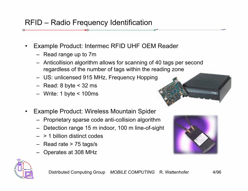
• Example Product: Intermec RFID UHF OEM Reader– Read range up to 7m– Anticollision algorithm allows for scanning of 40 tags per second
regardless of the number of tags within the reading zone– US: unlicensed 915 MHz, Frequency Hopping– Read: 8 byte < 32 ms– Write: 1 byte < 100ms
• Example Product: Wireless Mountain Spider– Proprietary sparse code anti-collision algorithm– Detection range 15 m indoor, 100 m line-of-sight– > 1 billion distinct codes– Read rate > 75 tags/s– Operates at 308 MHz

Distributed Computing Group MOBILE COMPUTING R. Wattenhofer 4/97
RFID – Radio Frequency Identification
• Relevant Standards– American National Standards Institute
• ANSI, www.ansi.org, www.aimglobal.org/standards/rfidstds/ANSIT6.html– Automatic Identification and Data Capture Techniques
• JTC 1/SC 31, www.uc-council.com/sc31/home.htm, www.aimglobal.org/standards/rfidstds/sc31.htm
– European Radiocommunications Office• ERO, www.ero.dk, www.aimglobal.org/standards/rfidstds/ERO.htm
– European Telecommunications Standards Institute• ETSI, www.etsi.org, www.aimglobal.org/standards/rfidstds/ETSI.htm
– Identification Cards and related devices• JTC 1/SC 17, www.sc17.com, www.aimglobal.org/standards/rfidstds/sc17.htm,
– Identification and communication• ISO TC 104 / SC 4, www.autoid.org/tc104_sc4_wg2.htm,
www.aimglobal.org/standards/rfidstds/TC104.htm – Road Transport and Traffic Telematics
• CEN TC 278, www.nni.nl, www.aimglobal.org/standards/rfidstds/CENTC278.htm– Transport Information and Control Systems
• ISO/TC204, www.sae.org/technicalcommittees/gits.htm, www.aimglobal.org/standards/rfidstds/ISOTC204.htm

Distributed Computing Group MOBILE COMPUTING R. Wattenhofer 4/98
RFID – Radio Frequency Identification
• ISO Standards– ISO 15418
• MH10.8.2 Data Identifiers• EAN.UCC Application Identifiers
– ISO 15434 - Syntax for High Capacity ADC Media– ISO 15962 - Transfer Syntax– ISO 18000
• Part 2, 125-135 kHz• Part 3, 13.56 MHz• Part 4, 2.45 GHz• Part 5, 5.8 GHz• Part 6, UHF (860-930 MHz, 433 MHz)
– ISO 18047 - RFID Device Conformance Test Methods– ISO 18046 - RF Tag and Interrogator Performance Test Methods

Distributed Computing Group MOBILE COMPUTING R. Wattenhofer 4/99
ISM band interference
• Many sources of interference– Microwave ovens, microwave lightning– 802.11, 802.11b, 802.11g, 802.15, Home RF– Even analog TV transmission, surveillance– Unlicensed metropolitan area networks– …
• Levels of interference– Physical layer: interference acts like noise
• Spread spectrum tries to minimize this• FEC/interleaving tries to correct
– MAC layer: algorithms not harmonized• E.g., Bluetooth might confuse 802.11
Distributed Computing Group MOBILE COMPUTING R. Wattenhofer 4/100
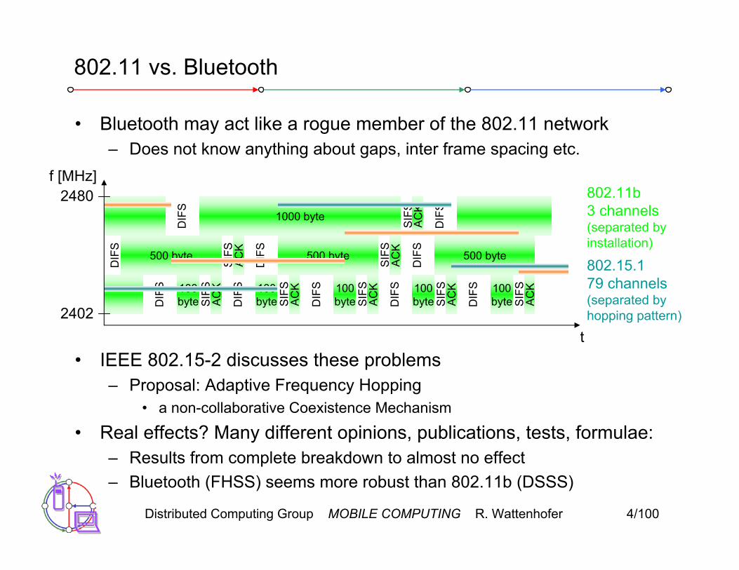
• Bluetooth may act like a rogue member of the 802.11 network– Does not know anything about gaps, inter frame spacing etc.
• IEEE 802.15-2 discusses these problems– Proposal: Adaptive Frequency Hopping
• a non-collaborative Coexistence Mechanism
• Real effects? Many different opinions, publications, tests, formulae:– Results from complete breakdown to almost no effect– Bluetooth (FHSS) seems more robust than 802.11b (DSSS)
802.11 vs. Bluetooth
t
f [MHz]
2402
2480 802.11b 3 channels(separated by installation)
ACK
DIF
S
DIF
S
SIF
S1000 byte
SIF
S
DIF
S
500 byte ACK
DIF
S500 byte
SIF
SAC
K
DIF
S
500 byte
DIF
S 100byte S
IFS
ACK
DIF
S 100byte S
IFS
ACK
DIF
S 100byte S
IFS
ACK
DIF
S 100byte S
IFS
ACK
DIF
S 100byte S
IFS
ACK
802.15.1 79 channels(separated by hopping pattern)