chapter 4 pfc buck-boost converter fed...
TRANSCRIPT

78
CHAPTER 4
PFC BUCK-BOOST CONVERTER FED PMBLDC MOTOR
4.1 GENERAL
The digital simulation of a Power Factor Correction (PFC) buck
boost converter based adjustable speed voltage controlled VSI fed PMBLDC
motor, is presented in this chapter. A single-phase AC-DC converter topology
followed by the buck-boost bridge converter, has been employed for the PFC
to ensure a near unity power factor over a wide speed range. The proposed
speed control scheme works on the concept of the DC link voltage control
proportional to the desired speed of the PMBLDC motor. The speed is
regulated by a PI controller. This drive ensures high accuracy and robust
operation from near zero to high speed.
This chapter presents an account of the average current control
technique used to design the cascaded buck-boost converter. Two loops are
attached to the buck boost converter in this design. The inner current loop has
a current error amplifier, which improves the power factor of the circuit
comparing the input current with the sinusoidal current reference. The outer
loop regulates the output voltage and also minimizes distortion. This drive
ensures high accuracy, improved power factor, robust operation from near
zero to high speed, higher efficiency, reduced component stresses, and the
ability to arbitrarily choose the DC output voltage. This converter also has
lower voltage stresses compared with the boost converter.

79
Single stage PFC circuits presented serious challenges recently,
when they sought to increase the output power capability with optimized
component ratings. A non-inverting buck-boost based PFC converter
operating in the conduction-mode for wide input voltage range applications
has been proposed. Unlike other PFC converters, the proposed non-inverting
buck-boost based PFC converter has both step-up and step-down conversion
functionalities to provide positive DC output-voltage. It is also well known,
that distorted voltages and current waveforms produce additional power
losses, and high frequency noise that can affect not only the power load, but
also the associated controllers.
Power factor correction can be achieved by any one of the
numerous techniques available. The most popular method used in the industry
is boost topology. This topology can operate in the continuous conduction
mode for high power application, or in the discontinuous conduction mode for
a lower power output. The buck regulator can also be used but the resulting
efficiency is lower than that of the boost converter. The drawback of this
approach is the sharp turn off power conversion, as the instantaneous line
voltage falls below the output voltage and these results in the rise of
harmonics. The applications of the boost converter are limited, since the
basic requirement is that the output voltage must be higher than the input
voltage. When a buck boost converter is used a higher power factor can be
obtained over a wide range of output voltage.
The proposed method combines the buck and boost modes in one
power stage and provides a simple solution for the unity power factor AC/DC
converter. A Buck Boost converter based PFC converter for a PMBLDC
motor will be discussed in this chapter. There are two loops attached to the
buck boost converter. The inner loop is the current loop with a current error
amplifier, to improve the power factor of the system, comparing the input

80
current with the sinusoidal current reference. The voltage error amplifier in
the outer loop regulates the output voltage and minimizes distortion. The
basic requirement of a Boost converter is that the output voltage must be
higher than the input voltage, and this factor limits its application to a narrow
range of output voltage. When a buck boost converter is used, a higher power
factor is obtained over a wide range of output voltage.
The conventional active PFC converter has to employ an
uncontrolled rectifier, and a costly boost inductor, but these power
components result in power loss, low efficiency and high cost. Additionally,
in the conventional active PFC converter, the power switches are in an ON
and OFF state in the whole mains period, enduring high voltage and current
stresses, which produce considerable switching loss and conduction loss
limiting the efficiency. Based on the operation of the switches, the buck-boost
converter has two operational modes to provide both step-up and step-down
voltage conversion functionality, including the buck plus boost and buck-
boost modes.
4.2 MATHEMATICAL MODEL OF THE PFC BUCK- BOOST
CONVERTER
A typical topology of the non-isolated (transformerless) buck-boost
converter is shown in Figure 4.1, and it is constructed with an uncontrolled
diode bridge. This is followed by a buck-boost converter (BBC), which
consists of an AC input supply voltage, diode bridge rectifier, Capacitor C,
inductor L, power switch S, and load resistance R. It allows the output voltage
to be higher or lower than the input voltage, depending on the duty ratio ‘d’ .
The storage elements in the circuit are the inductor and capacitor. With the
switch ON, the inductor current increases, and the diode D maintains OFF.
When the switch S is OFF, the diode provides the path for the inductor
current.

81
Figure 4.1 PFC buck boost converter topology
The state-space models provide a general and strong basis for the
dynamic modeling of various systems including power converters. The state
space models are useful for designing the linear control loops; they can also
be used to simulate the steady state, as well as the dynamic behavior of the
power converter, fitted with the designed feedback control loops and
subjected to external perturbations. The state-space averaging and
linearization provides an elegant solution for the application of widely known
linear control techniques to most power converters.
The voltage transfer gain of the buck-boost converter is
(1 )oV d
E d (4.1)
The corresponding current transfer gain is
m
(1 )I
oI dd (4.2)

82
In the on-duration circuit configuration, the switch conducts and the
diode does not conduct. State equations denoting the on-interval circuit
configuration are shown as Equations 4.3 – 4.9.
Ldi Edt L (4.3)
1cc
dV Vdt RC (4.4)
0 0 110 0
L
L
c Cf
diidt EL
dV VRCdt (4.5)
In the off-duration circuit configuration, the switch opens and the
diode conducts. The corresponding state equations for the off-circuit
topology are given as
L Cdi Vdt L (4.6)
1 1CL c
dV i Vdt C RC (4.7)
10
1 1
L
L
C C
diidt L
dV VC RCdt
(4.8)
Using the state space averaging model the system model is written
as

83
10
1 1 0
L
L
C C
di d didt L ELddV VC RCdt
(4.9)
The PFC buck-boost converter is designed for a supply voltage of
230V, L = 150 mH, C = 220 µF, R= 5 ..
4.3 SIMULATION RESULTS
The technical specifications of the drive system are as follows:
C= 2200 microfarad.TON= 5.88 µsecs. TOFF= 5.88µsecs.T= 11.76
µsecs. Stator Resistance is 2.875 ohms, Stator Inductance is 8.5e-3mH, and
Motor inertia is 0.8e-3J.
With the aid of the designed circuit parameters, MATLAB
simulation was done and the results are presented here. The speed was set at
1800 rpm and the load torque disturbances were applied at time t=1 sec.
Speed regulations were obtained at this speed, and the simulation results are
shown.
4.3.1 PMBLDC Motor Fed from the PFC Buck-Boost Converter
The Simulink model of the buck-boost converter is shown in
Figure 4.2. The Simulink model of the closed loop controlled PMBLDC
motor with PFC buck boost converter and a PI controller is shown in
Figure 4.3. A buck boost converter is used at the input to improve the power
factor. The AC input voltage and current waveforms are shown in Figure 4.4.
The step change in the load torque is shown in Figure 4.5.

84
Figure 4.2 Buck-boost Converter
Figure 4.3 Closed Loop Speed Control of the PMBLDC Motor with PFC buck-boost Converter
85
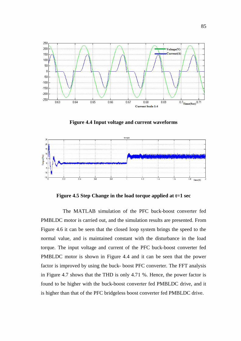
Figure 4.4 Input voltage and current waveforms
Figure 4.5 Step Change in the load torque applied at t=1 sec
The MATLAB simulation of the PFC buck-boost converter fed
PMBLDC motor is carried out, and the simulation results are presented. From
Figure 4.6 it can be seen that the closed loop system brings the speed to the
normal value, and is maintained constant with the disturbance in the load
torque. The input voltage and current of the PFC buck-boost converter fed
PMBLDC motor is shown in Figure 4.4 and it can be seen that the power
factor is improved by using the buck- boost PFC converter. The FFT analysis
in Figure 4.7 shows that the THD is only 4.71 %. Hence, the power factor is
found to be higher with the buck-boost converter fed PMBLDC drive, and it
is higher than that of the PFC bridgeless boost converter fed PMBLDC drive.

86
Figure 4.6 Speed Response Curve
Figure 4.7 FFT Analysis of the source current
4.4 EXPERIMENTAL RESULTS
After the simulation studies, the buck-boost converter fed
PMBLDC motor was fabricated and tested. The top view of the hardware is
depicted in Figure 4.8. The hardware consists of a power circuit, control
circuit and the PMBLDC motor. The experimental setup is shown in
Figure 4.9. The input voltage and current waveforms are shown in

87
Figure 4.10. The harmonic spectrum of source voltage is shown in
Figure 4.11.
The technical specifications of the drive system are as follows : L =
150 mH, C = 220 µF, R= 5 . Input voltage is 48V and the bridgeless boost
converter output is 58V .Other components are: Diode IN4007,
Microcontroller AT89C2051, MOSFET IRF840, Driver IR2110, Voltage
(0-500V) and Current is 8A.
Figure 4.8 Top View of the hardware

88
Figure 4.9 Experimental setup
Figure 4.10 Voltage and current waveforms

89
Figure 4.11 Harmonic Spectrum of the Source Voltage
4.5 CONCLUSION
Since the basic requirement of the popular boost converter is that
the output voltage must be higher than the input voltage, its applications are
limited. When a buck- boost converter is used, a higher power factor can be
obtained over a wide range of output voltage.
A PFC buck-boost converter based PMBLDC motor drive is
simulated, and the results compared with the experimental results. Feedback
signals from the PMBLDC motor representing the speed and position were
utilized to get the driving signals for the inverter switches through a PI
controller. The hardware was fabricated and tested. The experimental results
are in line with the simulation results. It has been found that the power factor
has increased with the use of the buck- boost converter. Efficiency increases
because of the increase in the power factor. The PFC feature of the buck-
boost converter has ensured that the power factor is close to unity.