chapter 4: material testing
TRANSCRIPT

CHAPTER 4 Materials Testing

Materials Testing •Mechanical properties are obtained by mechanical testing.
•Mechanical testing is used for developing design data, maintaining quality control, assisting in alloy development programs and providing data in failure analysis.

Mechanical testing is usually destructive and requires test specimens of the material to be machined or cut to the specific shape required by the test method.
cont,.

Describe material when a force is applied to it.
Determined through testing, usually involving destruction of material.
Extremely important to consider in design.
Mechanical Properties

a) Ductility
b) Toughness
c) Brittleness
d) Hardness
e) Plasticity
f) Elasticity
g) Strength
Types of mechanical properties

Ductility is a solid material's ability to deform under tensile stress; this is often characterized by the material's ability to be stretched into a wire.
Ductility

Tensile test of an AlMgSi alloy The local necking and the cup and cone fracture surfaces are typical for ductile metals.

Schematic appearance of round metal bars after tensile testing. a) Brittle fracture
b) Ductile fracture
c) Completely ductile fracture

Toughness •Toughness is the ability of a material to absorb energy and plastically deform without fracturing
• Material toughness is defined as the amount of energy per volume that a material can absorb before rupturing.
• It is also defined as the resistance to fracture of a material when stressed.
•Toughness requires a balance of strength and ductility.

A material is brittle if, when subjected to stress, it breaks without significant deformation (strain).
Brittle materials absorb relatively little energy prior to fracture, even those of high strength.
Breaking is often accompanied by a snapping sound. Brittle materials include most ceramics and glasses (which do not deform plastically) and some polymers, such as PMMA and polystyrene.
Many steels become brittle at low temperatures (see ductile-brittle transition temperature), depending on their composition and processing.
Brittleness

Brittle fracture in cast iron tensile test pieces

Graph comparing stress-strain curves for ductile and brittle materials.

Hardness is the degree of resistance to indentation, penetration, abrasion and wear.
Indentation hardness measures the resistance of a sample to permanent plastic deformation due to a constant compression load from a sharp object; they are primarily used in engineering and metallurgy fields. The tests work on the basic premise of measuring the critical dimensions of an indentation left by a specifically dimensioned and loaded indenter.
Common indentation hardness scales are Rockwell, Vickers, Shore, and Brinell.
Hardness
Plasticity is the propensity of a material to undergo permanent deformation under load.
Plasticity

Elasticity (or stretchiness) is the physical property of a material that returns to its original shape after the stress (e.g. external forces) that made it deform or distort is removed. The relative amount of deformation is called the strain.
Elasticity

Strength is the ability of a material to withstand various loads to which it is subjected during a test or service.
Strength

2 types of materials testing:
a) Destructive test
-results in the part being destroyed during the quality control testing program.
b) Non destructive test
- is done in such a manner that the usefulness of the product or part is not damaged or destroyed.
Materials Testing
Non destructive inspection techniques enable inspectors to check properties critical to the safe performance of metal parts without causing damage to the parts themselves.
This test is concerned with testing for cracks and flaws
Non Destructive Test
a) Dye penentrant test
b) Radiographic test
c) Magnetic particle test
d) Ultrasonic test
Types of non destructive test

It is easy to use and economical.
1) The specimen is coated with a red liquid dye which soaks into the surface crack or flaw.
2) The liquid is then washed off and the part dried.
3) A developer is dusted or sprayed on the part.
4) Flaws and cracks show up red against the white background of the developer.
Dye Penentrant Test

Cracks in a weld

This test involves passing gamma rays (X-rays) through a part and onto sensitive film to detect flaws in the metal.
The developed film has an image of the internal structure of the part.
A defect will show up on the film as a dark area.
X-rays are very sensitive and are capable of inspection any thickness of almost any kind of materials.
Radiographic test

This test is used to detect flaws on or near the surface of iron-based metals.
1) The part is first magnetized.
2) It is then either dusted with fine iron powder or coated with a solution in which iron particles are suspended.
3) Flaws in the workpiece cause the lines of magnetic force to become distorted and break through the surface.
4) There they attract concentrations of the iron particles, which reveal defects in the metal.
Magnetic particle test

The limitations of this technique are apparent when the flaw is parallel to the lines of magnetic force.
The flaw will not interrupt the force and no indication of it will appear when magnetic particles are applied.
Cont.

Concentration of the iron particle shows defect in the metal

This test use ultasonic sound waves to detect cracks and flaws in almost any material that can conduct sound.
Sound waves can also be used to measure the thickness from one side of the material.
Ultrasonic test

The human ear can hear sound waves with frequencies ranging from 20 to 20,000 Hertz.
Sound waves that vibrate with a frequency greater than 20,000 Hz are inaudible and are called ultrasonic.
Cont.

These high frequency sound waves are produced by a piezoelectric transducer.
The transducer is electrically pulsed and then vibrates at its own natural frequency.
1) In order to operate, the transducer must be joined to the piece being tested by a liquid coupling such as a film of oil, glycerin or water.
Cont.

2) The high frequency sound waves are transmitted through the material.
3) The flaws reflect the sound waves and are detected on an oscilloscope.
There is no size limitation on work that can be
tested by ultrasonic test.
Cont.

Ultrasonic Test

DESTRUCTIVE TEST

• Destructive testing is a costly and time consuming technique. A specimen is selected at random from a large number of pieces.
• Two types of destructive test:
a) Hardness test
b) Impact test
Destructive Testing

• 2 types of impact test:
a) Charpy impact test
b) Izod impact test
Impact Test


The Charpy specimen has a square cross section (10mm x 10mm) and contains a 45C V notch, 2 mm deep with a 0.25 mm root radius.
Charpy Impact Test

•The specimen is supported as a beam in a horizontal position and loaded behind the notch by the impact of a heavy swinging pendulum.
•The specimen is forced to bend and fracture at a high strain rate of the order 103 s-1.

Method of loading in Charpy and Izod tests.
Impact Testing Equipment
Izod and Charpy are the most common tests.
Both employ a swinging pendulum and conducted on small notched specimens. The notch concentrated the load at a point causing failure. Other wise without the notch the specimen will plastically deform throughout.
They are different in the design of the test specimen and the velocity at which the pendulum strikes the specimen.
Charpy: the specimen is supported as a single beam and held horizontally. Impacted at the back face of the specimen.
Izod: the specimen is supported as a cantilever and help vertically. Impacted at front face of the specimen.
Equipment

The energy absorbed in fracturing the specimen.
After breaking the test bar, the pendulum rebounds to a height which decreases as the energy absorbed in fracture increases.
The energy absorbed in fracture, usually expressed in joules, is rending directly from a calibrated dial on the impact tester.
The principal measurement
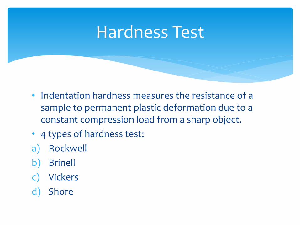
• Indentation hardness measures the resistance of a sample to permanent plastic deformation due to a constant compression load from a sharp object.
• 4 types of hardness test:
a) Rockwell
b) Brinell
c) Vickers
d) Shore
Hardness Test
The Rockwell hardness tester functions according to the depth of penetration made in metal by a specific kind of penetrator point forced by a given load.
Rockwell Hardness Test

Various Rockwell Scales

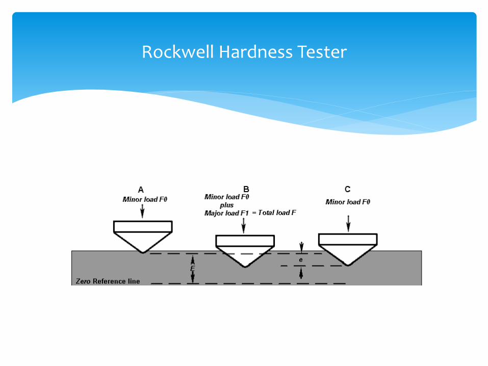
The determination of the Rockwell hardness of a material involves the application of a minor load followed by a major load, and then noting the depth of penetration.
The hardness value directly taken from a dial, in which a harder material gives a higher number.
Operation
Rockwell Hardness Tester

The Rockwell hardness test uses two loads that are applied sequentially.
A minor load of 10 kg is applied that helps seat the indenter and remove the effect of surface irregularities.
A major load which varies from 60 kg to 150 kg is then applied.
The difference in depth of indentation between the major and minor loads provides the Rockwell hardness number.
This number is taken directly from the dial on the machine.
Cont.

To get a reliable reading the thickness of the test piece should be at least 10 times the depth of the indentation.
The superficial Rockwell scales use lower loads and shallower impressions on brittle and very thin materials.
Cont.

1) its ability to display hardness values directly, thus obviating tedious calculations involved in other hardness measurement techniques.
2) typically used in engineering and metallurgy because of its speed, reliability, robustness, resolution and small area of indentation.
Advantages

Brinell hardness test use a machine to press a 10 mm diameter, hardened steel ball into the surface of the test specimen.
This machine applies a load for a specific period of time and causes an indentation that is used to calculate hardness.
Brinell Hardness Tester
Cont.

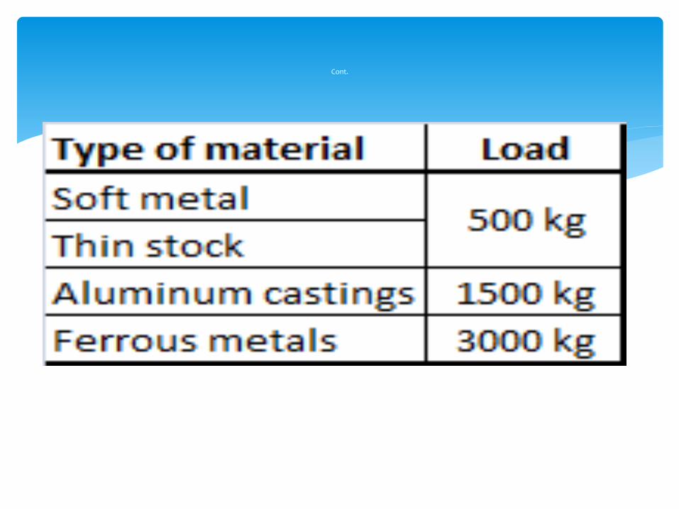
The load applied to the steel ball depends on the type of metal under test.
The load is usually applied for 10 to 15 seconds.
The diameter of the indentation is measured to ±0.5 mm using a low magnification portable microscope.
Cont.

The Brinell hardness number is found by measuring the diameter of the indentation and then finding the hardness
number on a calibrated chart.
The Vickers hardness test is similar in principle to the Brinell hardness test.
The major difference is that the indenter in the Vickers hardness test is a 136 square base diamond cone.
The load varies from 1 kg to 120 kg.
Vickers Hardness Tester

The specimen is placed on an anvil and raised by a screw until it is close to the point of the indenter.
The starting lever is tripped, allowing the load to be slowly applied to the indenter.
The load is released, the anvil lowered and a filar microscope is swung over to measure the diagonals of the square indentation to ±0.001 mm.
Diagonal measurements are averaged and the Vickers hardness number is followed by the letters HV.
Procedure

Extremely accurate readings can be taken.
one type of indenter covers all types of metals and surface treatment.
Advantages
An instrument that uses a test specimen that is freely supported horizontally and a glass tube that contains a diamond tipped hammer positioned vertically over the specimen.
The hammer is allowed to fall from a set height and the height of rebound is measured.
The test shows that the higher the rebound, the harder the specimen.
Shore Scleroscope Hardness Tester

Shore Scleroscope