chapter 4 hot-mix asphalt plant operations c4.1: general
TRANSCRIPT

Chapter 4 Hot-Mix Asphalt Plant Operations
Manual for Dense Graded Bituminous Mixes (DBM/BC)
C4
:
C4.1: General
The purpose of an HMA plant is to blend aggregate and asphalt together at an elevated temperature to
produce a homogeneous asphalt paving mixture. There are three basic types of HMA plants in use:
batch, parallel-flow drum-mix, and counter-flow drum-mix. All three types serve the same ultimate
purpose, and the asphalt mixture should be essentially similar regardless of the type of plant used to
manufacture it. The three types of plants differ, however, in operation and flow of materials, as
described in the following sections.
C4.2 : Asphalt Plants
C4.2.1 Batch Plant
The major components of a batch plant are the cold-feed system, asphalt supply system, aggregate
dryer, mixing tower, and emission-control system. A typical batch plant is depicted in Figure 4.1 the
major plant components are shown in Figure 4.2. The batch plant tower consists of a hot elevator, a
screen deck, hot bins, a weigh hopper, an Bitumen weigh bucket, and a pugmill. The flow of materials
in a batch tower is illustrated in Figure 4.3.
Figure 4.1 Typical Batch Plant
The aggregate used in the mix is removed from stockpiles and placed in individual cold-feed bins.
Aggregates of different sizes are proportioned out of their bins by a combination of the size of the
opening of the gate at the bottom of each bin and the speed of the conveyor belt under the bin.
Generally, a feeder belt beneath each bin deposits the aggregate on a gathering conveyor located under
all of the cold-feed bins. The aggregate is transported by the gathering conveyor and transferred to a
charging conveyor. The material on the charging conveyor is then carried up to the aggregate dryer.
The dryer operates on a counter-flow basis. The aggregate is introduced into the dryer at the upper end
and is moved down the drum by both the drum rotation (gravity flow) and the flight configuration
inside the rotating dryer. The burner is located at the lower end of the dryer, and the exhaust gases from
the combustion and drying process move toward the upper end of the dryer, against (counter to) the
flow of the aggregate. As the aggregate is tumbled through the exhaust gases, the material is heated and
dried. Moisture is removed and carried out of the dryer as part of the exhaust gas stream. The hot, dry
aggregate is then discharged from the dryer at the lower end.

Chapter 4 Hot-Mix Asphalt Plant Operations
Manual for Dense Graded Bituminous Mixes (DBM/BC)
C4
:
The hot aggregate is usually transported to the top of the plant mixing tower by a bucket elevator. Upon
discharge from the elevator, the aggregate normally passes through a set of vibrating screens into,
typically, one of four hot storage bins. The finest aggregate material goes directly through all the
screens into the hot bin; the coarser aggregate particles are separated by the different-sized screens and
deposited into one of the other hot bins. The separation of aggregate into the hot bins depends on the
size of the openings in the screen that is used in the screen deck and the gradation of the aggregate in
the cold-feed bins.
Figure 4.2 Major components of Batch Plant
The heated, dried, and resized aggregate is held in the hot bins until being discharged from a gate at the
bottom of each bin into a weigh hopper. The correct proportion of each aggregate is determined by
weight. At the same time that the aggregate is being proportioned and weighed, the bitumen is being
pumped from its storage tank to a separate heated weigh bucket located on the tower just above the
pugmill. The proper amount of material is weighed into the bucket and held until being emptied into the
pugmill.
The aggregate in the weigh hopper is emptied into a twin-shaft pugmill, and the different aggregate
fractions are mixed together for a very short period of time —usually less than 5 seconds. After this
brief dry-mix time, the Bitumen from the weigh bucket is discharged into the pugmill, and the wet-mix
time begins. The mixing time for blending of the Bitumen with the aggregate should be no more than
that needed to completely coat the aggregate particles with a thin film of the Bitumen material—usually
in the range of 25 to 35 seconds, with the lower end of this range being for a pugmill that is in good
condition. The size of the batch mixed in the pugmill can be in the range of 1.81 to 5.44 tonnes (2 to 6
tons).
When mixing has been completed, the gates on the bottom of the pugmill are opened, and the mix is
discharged into the haul vehicle or into a conveying device that carries the mix to a silo from which
trucks will be loaded in batch fashion. For most batch plants, the time needed to open the pugmill gates
and discharge the mix is approximately 5 to 7 seconds. The total mixing time (dry-mix time , wet-mix
time, mix discharge time) for a batch can be as short as about 30 seconds, but typically, the total mixing
time is about 35 seconds.
The plant is equipped with emission-control devices, comprising both primary and secondary collection
systems . A dry collector or knockout box is normally used as the primary collector. Either a wet
scrubber system or, more often, a dry fabric filter system (baghouse) can be used as the secondary
collection system to remove particulate matter from the exhaust gases that flow out of the dryer and
send clean air to the atmosphere through the stack.
Chapter 4 Hot-Mix Asphalt Plant Operations
Manual for Dense Graded Bituminous Mixes (DBM/BC)
C4
:
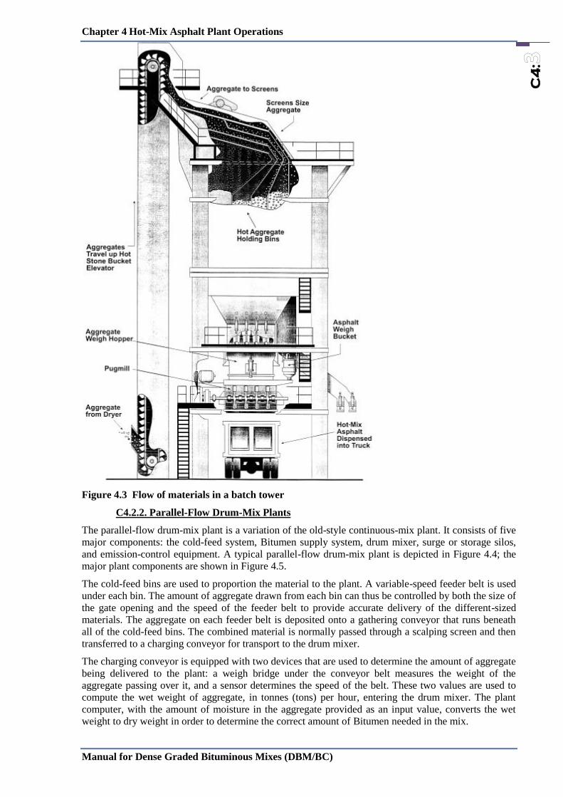
Figure 4.3 Flow of materials in a batch tower
C4.2.2. Parallel-Flow Drum-Mix Plants
The parallel-flow drum-mix plant is a variation of the old-style continuous-mix plant. It consists of five
major components: the cold-feed system, Bitumen supply system, drum mixer, surge or storage silos,
and emission-control equipment. A typical parallel-flow drum-mix plant is depicted in Figure 4.4; the
major plant components are shown in Figure 4.5.
The cold-feed bins are used to proportion the material to the plant. A variable-speed feeder belt is used
under each bin. The amount of aggregate drawn from each bin can thus be controlled by both the size of
the gate opening and the speed of the feeder belt to provide accurate delivery of the different-sized
materials. The aggregate on each feeder belt is deposited onto a gathering conveyor that runs beneath
all of the cold-feed bins. The combined material is normally passed through a scalping screen and then
transferred to a charging conveyor for transport to the drum mixer.
The charging conveyor is equipped with two devices that are used to determine the amount of aggregate
being delivered to the plant: a weigh bridge under the conveyor belt measures the weight of the
aggregate passing over it, and a sensor determines the speed of the belt. These two values are used to
compute the wet weight of aggregate, in tonnes (tons) per hour, entering the drum mixer. The plant
computer, with the amount of moisture in the aggregate provided as an input value, converts the wet
weight to dry weight in order to determine the correct amount of Bitumen needed in the mix.

Chapter 4 Hot-Mix Asphalt Plant Operations
Manual for Dense Graded Bituminous Mixes (DBM/BC)
C4
:
The conventional drum mixer is a parallel-flow system—the exhaust gases and the aggregate move in
the same direction. The burner is located at the upper end (aggregate inlet end) of the drum. The
aggregate enters the drum either from an inclined chute above
the burner or on a Slinger conveyor under the burner. The aggregate is moved down the drum by a
combination of gravity and the configuration of the flights located inside the drum. As it travels, the
aggregate is heated and the moisture removed. A dense veil of aggregate is built up near the midpoint of
the drum length to assist in the heat-transfer process.
Figure 4.4 A typical parallel-flow drum-mix plant
Figure 4.5 Major plant components of parallel-flow drum-mix plant

Chapter 4 Hot-Mix Asphalt Plant Operations
Manual for Dense Graded Bituminous Mixes (DBM/BC)
C4
:
The new aggregate and reclaimed material, if used, move together into the rear portion of the drum. The
Bitumen is pulled from the storage tank by a pump and fed through a meter, where the proper volume
of Bitumen is determined. The binder material is then delivered through a pipe into the rear of the
mixing drum, where the Bitumen is injected onto the aggregate. Coating of the aggregate occurs as the
materials are tumbled together and moved to the discharge end of the drum. Mineral filler or baghouse
fines, or both, are also added into the back of the drum, either just before or in conjunction with the
addition of the bitumen.
The asphalt mix is deposited into a conveying device (a drag slat conveyor, belt conveyor, or bucket
elevator) for transport to a storage silo. The silo converts the continuous flow of mix into a batch flow
for discharge into the haul vehicle.
In general, the same type of emission-control equipment is used on the drum-mix plant as on the batch
plant. A primary dry collector and either a wet scrubber system or a baghouse secondary collector can
be used. If a wet scrubber system is used, the collected fines cannot be re cycled back into the mix and
are wasted; if a baghouse is used, the collected fines can be returned in whole or in part to the mixing
drum, or they can be wasted.
C4.2.3. Counter-Flow Drum-Mix Plants
A more recent development in drum-mix plant design is the counter-flow drum-mix plant. Its design
represents an effort to improve the heat transfer process in side the drum and to reduce plant emissions.
In the counter-flow drum-mix plant, the heating and drying of the aggregate are accomplished in a
manner similar to that of a conventional batch plant dryer.
Figure 4.6 Counter-flow drum mixer with mixing unit extended on the end of the aggregate
dryer.
Two basic types of counter-flow drum-mix plants are in use. The first, shown in Figure 4.6, has the
mixing unit extended on the end of the aggregate dryer portion of the drum. The second, shown in
Figure 4.7, has the mixing unit folded back around the aggregate dryer portion of the drum. With both
designs, the aggregate enters the drum from the upper end. The burner, however, is located near the
lower end of the drum, similar to its position on a batch plant dryer. The aggregate moves down the
drum against the flow of the exhaust gases in a counter-flow direction. No Bitumen is introduced into
the aggregate within the main (drying) portion of the drum. The mixing of the binder material with the
heated and dried aggregate is accomplished completely outside of the exhaust gas stream—behind or
underneath the burner.
In the counter-flow drum-mix plant design shown in Figure 4.6, the hot aggregate passes the burner into
a mixing zone. At the upper end of the mixing zone, the baghouse fines or mineral filler (or both) are
added to the aggregate. A short distance later, the binder material is introduced into the drum. The
mixing of the aggregate and Bitumen thus takes place behind (down stream of) the dryer in a separate
mixing zone, out of contact with the exhaust gases from the burner.

Chapter 4 Hot-Mix Asphalt Plant Operations
Manual for Dense Graded Bituminous Mixes (DBM/BC)
C4
:
In the counter-flow drum-mix plant design shown Figure 4.7, the inner drum acts as an aggregate dryer,
and the outer drum serves as the mixing unit. The Bitumen is introduced into the aggregate after the
aggregate has been discharged from the inner into the outer drum. The blending of the two materials
occurs as the aggregate and Bitumen are conveyed back uphill in the outer drum by a set of mixing
paddles attached to the inner drum. The inner drum rotates, whereas the outer drum is stationary. This
type of counter-flow drum-mix plant is known commercially as a double-barrel plant because of the
double-drum setup. Any mineral filler or baghouse fines, enters the drum in the double-barrel process
between the inside and outside drums. Thus, as with the design shown in Figure 4.6, the material is kept
away from the exhaust gases from the burner.
Figure 4.7 Counter-flow drum mixer with mixing unit folded around aggregate dryer.
C4.3 :Aggregate Storage and Handling
The storage and handling of new aggregate for use in any type of asphalt plant are addressed in this
section. Proper stockpiling techniques, both for placement of the aggregate in the stockpile and for
removal of the aggregate from the stockpile, are important. Another stages of handling are the discharge
of the aggregate from the cold-feed bins onto the individual feeder belts; the passage of the aggregate
onto the gathering conveyor; and the delivery of the aggregate, sometimes through a scalping screen, to
the charging conveyor and finally to the batch plant dryer or drum-mixer. The use of a weigh bridge
system on the charging conveyor on a drum-mix plant to determine the amount of aggregate being fed
into the drum is also addressed.
C.4.3.1 Aggregate Stockpiles
Quality control of HMA, regardless of whether a batch or drum-mix plant is used to manufacture the
mix, begins with the stockpiles of aggregate that are to be processed through the plant and incorporated
into the mix. The aggregate should be stored on a sloped, clean, stable surface, with the different sizes
of coarse and fine aggregate kept separated. Care should be exercised during both the stockpiling and
removal processes to minimize segregation of the aggregate in each pile. If segregation of a particular
size of coarse or fine aggregate does occur, an effort should be made to blend the segregated materials
together before the aggregate is delivered into the cold-feed bins. This is difficult to do, however, and
care must be taken with this operation to keep from aggravating the segregation problem.
Building Stockpiles
Aggregate should be stockpiled on a clean, dry, stable surface and should not be allowed to become
contaminated with foreign materials such as dust, mud, or grass. Fugitive dust in the aggregate
stockpile area should be controlled so that the dust does not coat the surface of the aggregates and thus

Chapter 4 Hot-Mix Asphalt Plant Operations
Manual for Dense Graded Bituminous Mixes (DBM/BC)
C4
:
does not alter the gradation of the material in each stockpile. The stockpiles should be constructed to be
free draining to ensure that the moisture content of the aggregate is as low as possible. Paved stockpile
pads should be used to facilitate drainage and provide a solid working platform. Excess moisture,
particularly in the fine aggregates (sand), increases the cost of drying the aggregates and reduces the
production capacity of the plant. When using a drum-mix plant, the moisture content of each aggregate
size should be determined at least twice a day and the average moisture content of the combined
aggregates entered into the plant computer system.
Figure 4.8 Covered aggregate stockpiles.
To reduce the amount of moisture that accumulates in the aggregate, especially from rain, it is often
cost-effective to cover the aggregate stockpiles. The cover typically is in the form of a roof or a shed, as
seen in Figure 4.8. A tarp placed directly on top of the aggregate should generally not be used since
moisture will typically collect under the tarp instead of evaporating. If only one roof is used, it should
be placed on top of the fine aggregate pile since this material will typically have a higher moisture
content than that of the coarser aggregate. If multiple roofs are available, they should then be placed
over the various coarse aggregate stockpiles.
As noted, the stockpiles of the various aggregate sizes should be kept separated—by physical barriers,
if necessary—at all times. The cold-feed bins and feeders are calibrated to provide a specific amount of
each size of aggregate from each bin. If the various materials are blended in the stockpiles, a
combination of sizes will occur in each cold-feed bin. This blending of the aggregate will cause
variations in the gradation of the HMA produced by a drum-mix plant and may cause problems with
unbalanced hot bins in a batch plant.
Segregation is a major concern with stockpiled aggregate. Many aggregate problems are caused by
mishandling of the aggregate during stockpiling and load-out operations. Whenever possible,
aggregate should be stockpiled by individual size fractions. A well-graded or continuously graded
material should not be contained in one stockpile. Aggregate of larger sizes, particularly when
combined with that of smaller sizes, has a tendency to roll down the face of a stockpile and collect at
the bottom, leading to segregation.
Prevention of segregation begins with the construction of the stockpile. If possible, stockpiles should be
constructed in horizontal or gently sloping layers. If trucks are used to carry the incoming aggregate to
the plant site, each load should be dumped in a single pile, as seen in Figure 4.9. Any construction
procedure that results in the aggregate being pushed or dumped over the side of the stockpile should be
avoided because these practices may result in segregation. Trucks and loaders should be kept off the
stockpiles since they can cause aggregate breakage, fines generation, and con tamination of the
stockpile.
Chapter 4 Hot-Mix Asphalt Plant Operations
Manual for Dense Graded Bituminous Mixes (DBM/BC)
C4
:
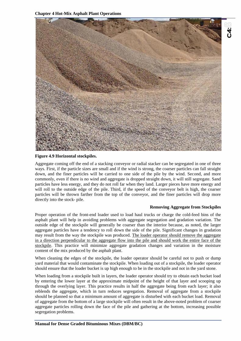
Figure 4.9 Horizontal stockpiles.
Aggregate coming off the end of a stacking conveyor or radial stacker can be segregated in one of three
ways. First, if the particle sizes are small and if the wind is strong, the coarser particles can fall straight
down, and the finer particles will be carried to one side of the pile by the wind. Second, and more
commonly, even if there is no wind and aggregate is dropped straight down, it will still segregate. Sand
particles have less energy, and they do not roll far when they land. Larger pieces have more energy and
will roll to the outside edge of the pile. Third, if the speed of the conveyor belt is high, the coarser
particles will be thrown farther from the top of the conveyor, and the finer particles will drop more
directly into the stock pile.
Removing Aggregate from Stockpiles
Proper operation of the front-end loader used to load haul trucks or charge the cold-feed bins of the
asphalt plant will help in avoiding problems with aggregate segregation and gradation variation. The
outside edge of the stockpile will generally be coarser than the interior because, as noted, the larger
aggregate particles have a tendency to roll down the side of the pile. Significant changes in gradation
may result from the way the stockpile was produced. The loader operator should remove the aggregate
in a direction perpendicular to the aggregate flow into the pile and should work the entire face of the
stockpile. This practice will minimize aggregate gradation changes and variation in the moisture
content of the mix produced by the asphalt plant.
When cleaning the edges of the stockpile, the loader operator should be careful not to push or dump
yard material that would contaminate the stockpile. When loading out of a stockpile, the loader operator
should ensure that the loader bucket is up high enough to be in the stockpile and not in the yard stone.
When loading from a stockpile built in layers, the loader operator should try to obtain each bucket load
by entering the lower layer at the approximate midpoint of the height of that layer and scooping up
through the overlying layer. This practice results in half the aggregate being from each layer; it also
reblends the aggregate, which in turn reduces segregation. Removal of aggregate from a stockpile
should be planned so that a minimum amount of aggregate is disturbed with each bucket load. Removal
of aggregate from the bottom of a large stockpile will often result in the above-noted problem of coarser
aggregate particles rolling down the face of the pile and gathering at the bottom, increasing possible
segregation problems.

Chapter 4 Hot-Mix Asphalt Plant Operations
Manual for Dense Graded Bituminous Mixes (DBM/BC)
C4
:
Besides working the face of the stockpile, the loader operator should use sound stockpile management
techniques. A good practice is to rotate stockpiles so that the first material put into the stockpile is
removed first. Areas of the stockpile that are segregated should be re-blended by the loader operator at
the stockpile. The operator should not feed one or two loads of coarse aggregate and then one or two
loads of fine aggregate into the cold-feed bins in an attempt to blend the aggregate. Doing so will cause
significant problems in achieving the required aggregate gradation in the mix, regardless of what type
of plant is used to produce the mix. It should be noted that the best approach to minimizing segregation
is always to use proper stockpiling techniques in the first place, as discussed above, and not to rely on
the loader operator to reblend segregated materials adequately.
C4.4: Cold-Feed Systems for Aggregate
Typically the cold-feed systems on HMA batch and drum-mix plants are similar. Each consists of cold-
feed bins, feeder conveyors, a gathering conveyor, and a charging conveyor. On most drum-mix plants
and on some batch plants, a scalping screen is included in the system at some point.
Figure 4.10 Flow of material through a drum-mix plant (continuous-flow facility).
C.4.4.1 Cold-Feed Bins and Feeder Conveyors
The flow of aggregates through a plant begins at the cold-feed bins, as seen in Figure 4.10. The plant is
equipped with multiple bins to handle the different sizes of new aggregate used in the mix. Most cold-
feed bins are rectangular in shape, have sloping sides, and have a rectangular or trapezoidal opening at
the bottom. A bulkhead or divider should be used between each cold-feed bin to prevent overflow of
the aggregate from one bin into another. The resulting commingling of aggregate sizes can significantly
alter the gradation of the mix being produced, particularly in a drum-mix plant, where no screens are
used to resize the aggregate after it is dried. If bulkheads are not in place between the cold-feed bins
and mixing of the different-sized aggregates is a problem, these devices should be installed. Care
should be taken not to pile aggregate higher than the top of the bulkheads, again to prevent aggregate in
one bin from spilling over into the adjacent bin. If bins overflow, the resulting contamination of
aggregate materials will lead to a difference in the gradation of the produced HMA mix.

Chapter 4 Hot-Mix Asphalt Plant Operations
Manual for Dense Graded Bituminous Mixes (DBM/BC)
C4
:
Each cold-feed bin is equipped with a gate to control the size of the discharge opening on the bin and a
feeder belt to draw aggregate out of each bin at a controlled rate. On some plants, the speed of the
feeder belt under the bin is not variable; the amount of aggregate that is withdrawn from the bin is
determined by the setting of the gate opening. The degree of control exercised over the amount of
aggregate withdrawn from each bin is thus governed by the number of possible gate settings on each
feeder gate. The size of the gate opening is set by raising or lowering the gate using a manual or
electric-powered crank or wheel, or by unbolting, moving, and rebolting a sliding plate on one end of
the bin.
Figure 4.11 Continuous feeder belt.
Most cold-feed bins are equipped with variable-speed feeder belts under each bin, as shown in Figure
4.11. The gate opening and the feeder belt speed for each bin are set to deliver an amount
corresponding to the desired proportion of that aggregate needed in the mix. The more a particular
aggregate is required, the larger is the opening of the bin discharge gate. The speed of each belt is then
set in accordance with the exact amount of material withdrawn from the bin. If a small change is needed
in the amount of material to be delivered from a bin, the speed of the feeder belt can be increased or
decreased to accommodate that change. Theoretically, it is possible to withdraw aggregate from a bin
using the full range of the belt speed, from 1 to 100 percent of the maximum speed. In practice, only 20
to 80 percent of the maximum belt speed (ideally closer to 50 percent) should be used when adjusting
the rate of aggregate feed. This practice allows the plant operator some leeway to vary the production
rate of each feeder for changes in operating conditions without having to change the settings of the gate
openings.
If a large change is needed in the feed rate for a particular size of aggregate, however, the gate opening
at the discharge end of the bin will need to be adjusted. The speed setting of each feeder belt is
displayed on the operator’s console in the plant control trailer and is typically shown as a percentage of
the maximum belt speed. If the feeder belt under a given cold-feed bin is operating at less than 20
percent or more than 80 percent of maximum speed, the gate setting may need to be changed so that the
belt can operate closer to the middle of its speed range for the selected production rate.
The speed setting for each feeder belt is adjusted independently to allow the proper amount of
aggregate to be pulled from each bin. Once determined, the speed of all the feeder belts is synchronized
so that a change in the speed of one is proportional to the change in the speed of all the others. Thus if
the production of the plant is increased from 225 to 320 tonnes (250 to 350 tons) per hour, a change in
the master control setting causes a corresponding change in the speed of all the feeder belts.
Each cold-feed bin and its companion feeder belt should be equipped with a no-flow sensor (typically a
limit switch) that will alert the operator when no aggregate is coming out of the cold-feed bin. If the bin
is empty or the aggregate has bridged over the discharge opening in the bin, and no material is being
discharged onto the collecting conveyor, the no-flow sensor will indicate the condition by sounding an
audible alarm or automatically shutting down the plant after a preset time.
C.4.4.2 Collecting Conveyor
Aggregate deposited from each feeder belt is dropped onto a collecting conveyor, located beneath all of
the individual feeder conveyors, that collects the aggregate discharged from each of the bins. The speed

Chapter 4 Hot-Mix Asphalt Plant Operations
Manual for Dense Graded Bituminous Mixes (DBM/BC)
C4
:
of the conveyor is constant. The amount of aggregate deposited on this conveyor is thus a function of
the size of the gate opening and the speed of the feeder conveyor under each cold-feed bin.
To reduce the amount of buildup that may occur on this conveyor, particularly when the various
aggregates are wet, the coarser aggregates should be placed on the belt first. The sand, which typically
has the higher moisture content, may stick to the conveyor belt if placed on the belt first and may need
to be continually removed. This may, in turn, affect the gradation of the aggregate in the mix.
C.4.4.3 Scalping Screens and Devices
On drum-mix plants it is desirable to insert a scalping screen into the cold-feed system to prevent
oversized material from entering the mixer. Scalping can sometimes be accomplished by placing a
screen over the top of the cold-feed bins. In many cases, however, this screen is only a grizzly type of
device with relatively large openings. Because of the large volume of aggregate that is delivered at one
time from the front-end loader to a cold-feed bin, a screen with small openings cannot properly handle
the flow of aggregate from the loader bucket to the bin. Thus, scalping screens employed on top of the
cold-feed bins are normally used only for the larger-sized coarse aggregate.
Figure 4.12 Typical arrangement of Scalping Screens and Devices
A scalping screen is used to remove larger-sized deleterious materials such as tree roots, vegetable
matter, and clay lumps, as well as oversized aggregate, from the aggregate material. As shown in Figure
4.12, the scalping screen is most often placed somewhere between the end of the collecting conveyor
and the drum. While it is not always necessary to pass quarry-processed aggregates through a scalping
screen, it is good practice to do so to prevent any extraneous oversized material from entering the drum
and thus the mix. A scalping screen should be used as part of the cold-feed system on a batch plant if
the screens have been removed from the mixing tower or if the screens are bypassed. The openings in
the scalping screen (the bottom screen if a double-deck screen is being used) are typically slightly
larger than the maximum-sized aggregate used in the mix.
Scalping devices can be tailored to the needs of the individual plant. Typically only a single-deck
scalping screen is used. Some plants, however, employ a double-deck scalping screen, which controls
two different top-size aggregates without requiring changing of the screen. If both screens are being
used, a flop gate at the lower end of the second screen is employed to redirect the aggregate caught on
the bottom screen to the charging conveyor. The flop gate can be operated either manually or
automatically. The openings in the screen can be either square or slotted. The advantage of the slotted
screen is that a smaller screen area can be used to handle a given volume of material.
Collective Conveyor Scalping Screens

Chapter 4 Hot-Mix Asphalt Plant Operations
Manual for Dense Graded Bituminous Mixes (DBM/BC)
C4
:
Some scalping screens are equipped with a bypass chute. This device allows the aggregate on the
collecting conveyor to be deposited directly on the charging conveyor without passing through the
screen. This procedure is sometimes used when quarry-processed aggregate or aggregate known to be
free of deleterious material is fed to the plant.
One make of cold-feed bins includes a small scalping screen under each cold-feed bin instead of a
scalping screen at the end of the collecting conveyor. The aggregate from a particular bin falls off the
feeder belt and onto the scalping screen. Material of the proper size passes through the screen and onto
the collecting conveyor. Oversized pieces are rolled down the screen into a reject chute that deposits
this aggregate in a pile be side each bin for subsequent disposal. Because these individual bin scalping
screens are very small, the proper amount of aggregate will not pass through the screen onto the
charging conveyor if they become blinded or clogged. Thus the operation of such scalping screens
should be monitored on a regular basis.
C.4.4.4 Charging Conveyor
Batch Plants
The combined coarse and fine aggregates are discharged from the gathering conveyor onto the charging
conveyor for transport to the drum. For a batch plant, this conveyor delivers the aggregate to the
inclined chute at the upper end of the dryer. The charging conveyor is a simple belt that operates at a
constant speed but carries a variable amount of aggregate, depending on the volume of aggregate
delivered from the cold-feed bins. The conveyor should normally be equipped with a device such as a
scraper blade or brush, located on the underside of the belt, to clean off the belt as it revolves. This
device will prevent any buildup of aggregate on the belt. If a significant amount of fine aggregate
(sand) continually builds up on the belt and must be removed, the order of aggregate placed on the
gathering conveyor from the cold-feed bins should be changed, if necessary, so that the coarser
aggregates are placed on that belt first.
Drum-Mix Plants
Figure 4.13 How a weigh bridge works.
For a parallel-flow drum-mix plant, the charging conveyor carries the aggregate to a charging chute
above the burner on the drum or to a Slinger conveyor under the burner. From one of these two entry
points, the aggregates are introduced into the mixing drum. For a counter-flow drum-mix plant, the
charging conveyor carries the aggregate to an inclined chute at the upper end of the drum. For both
types of plant, the charging conveyor contains a weigh bridge system that measures the amount of

Chapter 4 Hot-Mix Asphalt Plant Operations
Manual for Dense Graded Bituminous Mixes (DBM/BC)
C4
:
aggregate, in tonnes (tons) per hour, being fed to the drum mixer. The weigh bridge, or belt scale,
determines the weight of aggregate passing over the weigh idler. The charging conveyor operates at a
constant speed that is independent of the speed of the other conveyors. The weigh bridge itself is
located near the midpoint of the length of the charging conveyor.
A weigh idler, as shown in Figure 4.13, is the heart of the weigh bridge system. This idler is different
from the fixed idlers on the conveyor frame. It is free to move and is attached to a load cell. As the
aggregates pass over the weigh idler, the weight of the material is recorded as an electrical signal in the
computer control system. The weight value by itself is meaningless, however, because it covers only an
instant of time. Thus the charging conveyor is also equipped with a belt speed sensor, as shown in the
figure. This device, usually located on the belt take up pulley, is a tachometer, which, coupled with the
diameter of the pulley, is used to mea sure the actual speed of the conveyor belt.
To obtain an accurate belt speed reading, it is essential that the charging conveyor belt be tight around
the gravity takeup pulley, as shown in Figure 4.13. Any slippage of the belt over the speed sensor will
result in an erroneous reading and an incorrect wet aggregate weight input to the drum mixer. Some
conveyors are equipped with an air-actuated take up system, located on the tail shaft pulley, that
operates in a manner similar to that of the gravity take up system. The purpose of this system is to keep
the belt tight and eliminate the potential problem of inaccurate belt speed sensor readings.
The information from the weigh idler on the belt scale and from the belt speed sensor is combined to
determine the actual weight of the aggregate in tonnes (tons) per hour. This value is the wet weight and
includes the moisture in the aggregate. The wet weight is converted to dry weight by the plant computer
so that the proper amount of Bitumen will be added to the mix. The average moisture content in the
combined coarse and fine aggregates is input manually.
The moisture content of each of the aggregates being fed into the plant should be checked regularly and
the average amount of moisture in the incoming aggregate determined. This determination should be
made when ever the moisture content of the aggregate stockpiles has changed, such as after it has
rained, or a minimum of twice a day. This frequency can be reduced to a minimum of once a day during
periods of consistent dry weather conditions. An erroneous moisture content input into the computer
system will result in an inaccurate amount of binder material being added to the mix. If the actual
moisture content of the incoming aggregate is higher than the value input to the computer, slightly less
aggregate dry weight is actually being introduced into the drum, and a higher-than-desired amount of
bitumen is being added to the aggregate. Conversely, if the actual moisture content of the incoming
aggregate is lower than the value input to the computer, more aggregate is being introduced into the
mixing drum, and a slightly lower binder content will result. The difference in the asphalt content, of
course, will depend on the difference between the actual and input moisture values.
If the aggregates being carried on the belt are relatively dry, all the aggregates that pass over the weigh
bridge will enter the drum. As discussed earlier, how ever, if the moisture content of the aggregates is
high, some of the fine aggregate may stick to the charging conveyor belt. This “extra” material will not
be fed into the drum but will remain on the belt. If not removed by a scraper or brush, this material will
continually be detected by the weigh bridge, and the plant computer will calculate a greater weight of
aggregate entering the drum than is actually occurring. The computer will in turn signal the asphalt
pump to deliver more Bitumen to the plant to allow for the additional aggregate. Thus the belt scraper
or brush should be in place, continually cleaning the charging conveyor belt as it carries aggregate to
the mixing drum. The amount and gradation of the fine aggregate removed by the scraper will change
the gradation of HMA mix produced by the plant.
C.4.4.5 Mineral Feeding
The mineral filler can be added in one of several places. In some cases, it is placed in one of the plant
cold feed bins and fed into the plant as an additional aggregate component. The filler can also be fed
from a silo onto the aggregate gathering conveyor and then into the drum. In each case the material
must be placed between the layers of other aggregates on the cold feed conveyors to prevent blowing or
dusting of the mineral filler which would occur if the filler were spread on top of the coarse and fine
aggregates.
Many drum mix plants are equipped to feed the mineral filler into the rear end of the plant through a
filler feed line or auger system. A silo is employed to hold the filler and a vane feeder is used to
proportion the material into the conveying pipe. An air or pneumatic system blows the filler into the
drum where it is coated with the bitumen before it drops into the bottom of the drum.

Chapter 4 Hot-Mix Asphalt Plant Operations
Manual for Dense Graded Bituminous Mixes (DBM/BC)
C4
:
C.4.4.6 Addition of Hydrated Lime
To reduce the occurrence of moisture damage in the HMA mix, hydrated lime is sometimes added to
the mix at a rate of 1 to 2 percent by weight of aggregate. This material may be added in one of two
different forms— as a dry powder or as a slurry. If a slurry is used, it is typically proportioned as one
part hydrated lime to three parts water. The lime can be added by being mixed with the aggregate on the
cold-feed belt or by being introduced into the rear of the drum, similar to what is done with a
conventional mineral filler.
The dry lime or slurry is often added to the aggregate as it moves along the gathering conveyor or up
the charging conveyor. The lime is normally placed on top of the aggregate and is then mixed with the
aggregate either when the aggregate passes through the scalping screen, when it passes through a set of
plows or mixing paddles on the belt, or in an in-line pugmill placed in the cold-feed system between the
gathering conveyor and the charging conveyor. The amount of mixing of the lime that occurs as
aggregate passes through the scalping screen, however, is normally not enough to ensure that all of the
aggregate particles are adequately coated with lime. Therefore, this method should generally not be
used. If the lime is to be mixed with the aggregate on the gathering or charging conveyor, a set of plow
blades should be used to move the aggregate and the lime back and forth as the material moves up the
belt. An even better way to ensure that the hydrated lime is properly mixed with the coarse and fine
aggregate is to place a twin-shaft pugmill in the cold-feed system. This latter method distributes the
lime more uniformly throughout the aggregate particles.
C.4.4.7 Calibration
The rate of aggregate flow from each cold-feed bin should be determined to ensure that the proper
proportion of each aggregate is being delivered from the bin to the plant, so that the mix will have the
proper gradation. The method used to calibrate the cold-feed bins depends on the type of plant being
used and on the type of feeder belt under each bin.
Each cold-feed bin should be calibrated at a flow volume that will be within the range of material to be
delivered from the bin during mix production. Ideally, the bin should be checked at rates that are
approximately equal to 20, 50, and 80 percent of the estimated operational flow rate.
If a cold-feed bin is equipped with a constant-speed feeder belt, the only way to change the amount of
aggregate delivered from the bin is to vary the size of the gate opening. In this case, the size of the gate
opening at which the calibration procedure is conducted depends on the proportion of aggregate to be
drawn out of the bin. If, according to the mix design information, 25 percent of the total amount of
aggregate in the asphalt mix should come out of a given bin, that bin should be calibrated at the gate
opening size that will typically provide this rate of flow. In addition, the calibration procedure should be
completed at both the next-largest and next-smallest gate settings to allow for small changes in
production rate. If significant changes in production rate are anticipated, the cold-feed bins should be
calibrated at whatever gate openings are needed to provide the proper amount of that size of aggregate
to the plant.
Many cold-feed bins on batch plants and the vast majority of the cold-feed bins on both parallel-flow
and counter-flow drum-mix plants are equipped with a variable-speed feeder belt in addition to a means
of changing the size of the gate opening under the bin. The gate opening on the cold-feed bin should be
set at that level which will deliver the proper amount of aggregate for the desired plant production rate.
In addition, the bin should be calibrated at three different feeder belt speeds: 20, 50, and 80 percent of
the range of speed of the feeder belt. The optimum operating condition is for the cold-feed bin to
provide the proper amount of aggregate from the preset gate opening with the feeder belt operating at
approximately 50 percent of its maximum speed. Doing so allows the plant operator some latitude to
increase or decrease the production rate of the plant without having to change the setting of the gate
opening at the bottom of the cold-feed bins.
The calibration of each cold-feed bin is accomplished by drawing aggregate out of a bin for a specific
period of time and determining the weight of the aggregate delivered during that time. In most cases, a
truck’s empty (tare) weight is determined. Aggregate is withdrawn from the cold-feed bin and
delivered, usually by means of a diverter chute on the charging conveyor, into the truck. After a set
period of time, the flow of the aggregate is stopped, and the truck is weighed to determine the amount
of aggregate delivered. For cold-feed bins equipped with only a constant-speed feeder belt, the
weighing process is accomplished for a variety of gate opening settings. For cold-feed bins that are

Chapter 4 Hot-Mix Asphalt Plant Operations
Manual for Dense Graded Bituminous Mixes (DBM/BC)
C4
:
equipped with variable-speed feeder belts, the calibration process may be repeated at different gate
opening settings, with at least three different belt speeds per gate opening.
On a drum-mix plant, the weigh bridge must also be calibrated. This is accomplished by running
aggregate over the charging conveyor and thus the weigh idler for a given period of time. Instead of
being delivered to the drum mixer, the aggregate is diverted into an empty (tared) truck. After the
selected time period has passed, the aggregate flow is terminated, and the truck is weighed to determine
the amount of aggregate delivered. The weight thus determined is compared with the weight of
aggregate calculated by the plant computer system. The two weights should be within the tolerance
band set by the agency and typically within 1.0 percent of each other (assuming that the weigh bridge
and the truck scale are both accurate to 0.5 percent). It must be noted that both methods used to weigh
the material—the conveyor weigh bridge and the truck scale—must usually meet a tolerance of 0.5
percent of the true weight. Since one weight is being compared against the other and each has a
tolerance of 0.5 percent, the two weights should be within 1.0 percent of each other.
For many drum-mix plants, the weigh bridge should be calibrated at a production rate that is near the
estimated normal production rate for the plant. If the drum mixer is going to run at 90 percent of
capacity, the calibration of the weigh bridge should be completed at three production rates: 70, 85, and
100 percent of capacity. This calibration, however, will probably not be correct if the plant is run at a
much lower capacity, such as 60 percent. In this case, the calibration procedure should be repeated at
the lower production rate (bracketing the estimated rate with one rate above and one rate below the
most probable production level).
Because of the differences in the operating procedures of different makes and models of cold-feed bins
and asphalt plants, it is difficult to generalize the exact calibration procedure to use. The calibration
instructions provided with the plant should be followed.
C4.5: Bitumen Supply System
The Bitumen supply system consists of two major components. The first comprises one or more tanks
used to store the Bitumen until it is needed by the mixing plant. The second is a pump and meter system
used to draw Bitumen from the storage tank in proportion to the amount of aggregate being delivered to
the batch plant pugmill or drum mixer.
C.4.5.1 Storage Tanks
All Bitumen storage tanks must be heated to maintain the correct temperature of the Bitumen so its
viscosity will be low enough that it can be pumped and mixed with the heated and dried aggregate.
Most Bitumen storage tanks are heated by a hot-oil system and are equipped with a small heater to heat
and maintain the temperature of the oil. The hot oil is circulated through a series of coils inside the
storage tank, and the heat is then transferred from the oil, through the coils, to the bitumen. This heat
transfer process reduces the viscosity of the bitumen, causing it to flow upward and circulate or roll,
and causing new, lower-temperature Bitumen to come in contact with the heating oils. Thus the hot-oil
system, through a set of thermocouples and solenoid valves, maintains the proper temperature of the
bitumen, generally in the range of 150°C to 180°C, depending on the grade and type of Bitumen being
used.
Another common approach is to use electric heating elements to heat the asphalt tanks directly. Heating
elements that can be removed for servicing are submerged directly into the tank. Scavenger coils may
be installed in the asphalt tank to heat oil for asphalt lines and other parts of the plant requiring heat.
A less commonly used, much older style of Bitumen storage tank is the direct-fired tank. In this sys
tem, the Bitumen is heated by direct heat ex change from the combustion source, through a series of
heat tubes, to the bitumen. Care needs to be used with this type of tank to prevent overheating of the
bitumen immediately adjacent to the heat tubes.
All storage tanks should be completely insulated and heated, and all the lines for both Bitumen and
heating oil should be insulated to prevent loss of heat. Both the line used to fill the tank from the
bitumen transport truck or railcar and the discharge line from the tank to the plant should be located
near the bottom of the tank. The return line from the pump should be located so that the Bitumen enters
the tank at a level beneath the surface of the Bitumen stored in the tank and does not fall through the
air. This practice reduces the oxidation of the Bitumen during the circulation process.

Chapter 4 Hot-Mix Asphalt Plant Operations
Manual for Dense Graded Bituminous Mixes (DBM/BC)
C4
:
On most asphalt storage tanks, the discharge line to the batch or drum-mix plant is located at a point
closest to the plant to minimize the amount of pipe required. The return line for the Bitumen not used
by the plant (depending on the particular plant pump and meter setup, as discussed below) is typically
located on the same end of the storage tank. If it is desired to circulate the contents of the tank in order
to keep the material blended, the return line should be relocated to the opposite end of the tank.
Otherwise, only the material located at the end of the tank that contains the discharge and return lines
will be circulated.
If the HMA plant is equipped with more than one bitumen storage tank, the capability should exist to
pump material from one tank to another. It is important that the plant operator know from which tank
material is being pulled, especially if different grades or types of Bitumen are being stored in different
tanks. All Bitumen storage tanks contain a “heel” of material at the bottom of the tank. This material,
located beneath the heating coils, usually does not circulate efficiently. The volume of material in the
heel depends on the type and style of the storage tank, the location of the heating coils, and the amount
of time since the tank was
last cleaned. It is recognized, however, that some as phalt cement will typically remain in the bottom
of an “empty” tank. Therefore, placing Bitumen of one type or grade into a tank that previously
contained a dif ferent type or grade can cause an alteration of the prop erties of the Bitumen to the
point that it no longer meets specifications.
The capacity of an Bitumen storage tank is a function of its diameter and length. The amount of
material in the tank can be determined using a tank “stick.” The stick measures the distance from the
top of the dome or the top of the tank down to the level of the bitumen in the tank (the point at which
the tank stick just touches the top of the material). This distance is noted, and the amount of Bitumen in
the tank below this level is determined from the tank manufacturer’s calibration chart.
When Bitumen is delivered from a transport vehicle into a storage tank, it is important to ensure either
that the tank is clean or that it already contains the same type of material as that being pumped into the
tank. If it is empty at the time the new material is being added, the tank should be checked to ensure
that no water has accumulated in the bottom. If Bitumen is loaded on top of an asphalt emulsion or on
top of a layer of water in the tank, violent foaming of the Bitumen may occur, creating a serious safety
problem. Care should be taken to ensure that all valves are in the proper position to prevent pressure
from building up in the lines and causing an explosion.
Most bitumen storage tanks are horizontal. Increasingly, however, vertical tanks are being used.
Vertical tanks minimize separation of modifier in Bitumen and result in less overall area needed for
storage.
C.4.5.2 Pump and Meter System
Batch Plants
Batch plants typically employ one of two systems to transfer Bitumen from the storage tank to the
weigh bucket near the pugmill. The type of system used depends on the location of the return line
whether one or two Bitumen lines are present from the pump to the weigh bucket.
In the single-line process, two lines extend from the storage tank to the pump, but only one line extends
from the pump to the weigh bucket. The pump is a constant-volume, constant-speed unit that runs
continuously. Bitumen is always being pulled from the storage tank through the pump and circulated
back to the tank. When Bitumen is needed in the weigh bucket, a valve on the end of the line at the top
of the weigh bucket opens, and material is discharged into that bucket. When the proper amount of
Bitumen is in the bucket, as determined by weight, not volume, that valve is shut, and a pressure relief
valve at the pump is opened. The Bitumen then passes through the pump, but is re-circulated back to
the storage tank, in the second line, instead of being sent to the plant. A variation on this system allows
the Bitumen to circulate through the pump itself in stead of being returned back to the storage tank. In
the dual-line process, one line is used to deliver bitumen to the weigh bucket, and the second line is
used to return the “excess” Bitumen back to the storage tank. The Bitumen passes through the pump to
a three-way valve at the weigh bucket. When bitumen is needed in the weigh bucket, the valve opens,
and the material is discharged into the bucket. When the preselected weight is reached, the valve closes,
and the bitumen is re-circulated in the second line back to the storage tank.
Because the amount of Bitumen used in almost all batch plants is measured by weight, no correction is
needed for the temperature of the bitumen. On a few older batch plants, however, the amount of

Chapter 4 Hot-Mix Asphalt Plant Operations
Manual for Dense Graded Bituminous Mixes (DBM/BC)
C4
:
Bitumen delivered is determined by volume. In this case, the amount of Bitumen delivered to the
pugmill must be corrected in accordance with both the temperature and the specific gravity of the
bitumen. This can be accomplished using the procedure given in ASTM Specification D4311.
Drum-Mix Plants
Most drum-mix plants employ one of three systems to pull the Bitumen from the storage tank, meter it,
and pump it to the plant: (a) a variable-volume pump with a constant-speed motor, (b) a constant-
volume pump with a variable-speed motor, or (c) a constant-volume pump with a constant-speed motor
with a metering valve. The use of a particular pump and meter system is dependent on the make, model,
and date of manufacture of the plant and the choice of the plant owner.
With a system that uses a variable-volume pump driven by a constant-speed motor, the amount of
Bitumen pulled from the storage tank is controlled by changing the volume of Bitumen being pumped.
The volume needed at the pump is determined by the plant computer in proportion to the amount of
aggregate being fed into the plant. As the amount of aggregate entering the drum mixer increases, the
volume of Bitumen pulled through the pump also increases. When the plant is not using bitumen, the
material continually passes through the pump and meter and through a three-way valve that is set to
circulate the bitumen back to the storage tank instead of to the plant.
A second system incorporates a fixed-displacement (constant-volume) pump driven by a variable-speed
motor. The quantity of Bitumen delivered to the meter is varied by changing the speed of the motor.
The amount of material sent to the plant is also dependent on the aggregate feed rate. A three-way valve
in the system downstream of the meter allows the Bitumen to be re-circulated back to the tank when not
needed by the plant.
The third system consists of a constant-volume pump driven by a constant-speed motor. In this
arrangement, the same volume of Bitumen is pulled from the storage tank at all times. A proportioning
valve is placed in the line between the pump and the Bitumen meter. The position of the valve
determines the volume of material sent through the meter. The proportioning valve sends some of the
Bitumen through the meter and the rest back through the re-circulating line to the storage tank. The
system also has a valve downstream of the meter that allows the Bitumen sent through the meter to be
re-circulated to the tank. This valve is used during the warm-up period for the meter and during the
calibration process. Again, the position of the proportioning valve is determined by the rate of
aggregate feed into the drum mixer, both of which are con trolled by the plant computer.
With parallel-flow drum-mix plants, the bitumen line typically enters the drum from the rear, and the
binder material is discharged into the drum at a point normally one-quarter to one-third the length of the
drum, from the discharge end of the drum. With one type of counter flow drum-mix plant, the Bitumen
pipe is placed in the mixing unit portion of the drum, behind or below the burner, and the binder
material is added shortly after the aggregate passes out of the exhaust gas stream. In another type of
counter-flow drum-mix plant, the bitumen is added to the heated aggregate in the outer drum away from
the burner.
C.4.5.3. Temperature Compensation
Most bitumen meters measure the flow of bitumen by volume and convert this volume to weight using
the specific gravity and temperature of the bitumen. Bitumen expands when heated. Thus the volume of
Bitumen at 180°C will be somewhat greater than its volume at 150°C. This latter volume will be more
than the volume at 15°C , which is the standard temperature for determining the volume of bitumen
using conversion charts based on the specific gravity of the bitumen. If the specific gravity of the
bitumen and its temperature are known, however, the volume measured at the elevated temperature can
easily be converted to the standard volume at 15°C using the procedure given in ASTM Specification
D4311.
The volume of Bitumen moving through the meter likewise changes with temperature. Some meters are
set to measure the temperature of the Bitumen moving through the system and send that information,
together with the volume data, to the plant computer. The specific gravity of the Bitumen is set
manually on the controls. The computer then calculates the volume of Bitumen being fed into the plant
at the standard temperature of 15°C and converts that amount to a weight that is displayed on the plant
console.
On some meters, a temperature-compensating device is installed directly on the meter stand itself. As
the temperature of the Bitumen changes, the meter senses the change and, on the basis of the specific

Chapter 4 Hot-Mix Asphalt Plant Operations
Manual for Dense Graded Bituminous Mixes (DBM/BC)
C4
:
gravity of the bitumen, calculates the volume, at 15°C, passing through the meter. This corrected
volume (and corresponding weight) is then sent to the plant console for display.
Regardless of the particular arrangement employed, the asphalt pump system must be capable of
changing the volume of Bitumen passed through the meter in direct response to the demand of the
aggregate supply. The response of the pump system must be directly related to the change in the
amount of material mea sured by the aggregate weigh bridge system. In addition, the volume of
Bitumen measured at any given temperature must be converted to the volume at 15°C . At this standard
reference temperature, the weight of the Bitumen can be determined in terms of tonnes (tons) of
material per hour, as with the aggregate feed rate. The aggregate input and the weight of the bitumen
provides the production rate for the drum mixer, in tonnes (tons) of HMA per hour. As production rates
are adjusted, the asphalt pump system is timed so that the increase or decrease in Bitumen reaches the
drum at the same time that the increased or decreased material flow reaches that point in the drum.
Another type of asphalt meter, called a “mass-flow meter,” measures the flow of bitumen by weight
and, therefore, does not require temperature corrections
C.4.5.4. Calibration
The pump and meter system on a batch or drum-mix plant must be calibrated to ensure that the proper
amount of Bitumen is being delivered to the mix. For a batch plant operation, the amount of Bitumen
needed is measured by weight (although a few older batch plants measure the Bitumen by volume),
with the Bitumen being placed in the plant weigh bucket. For a drum-mix plant, the amount of Bitumen
is measured by volume as it is pumped through a meter into the rear of the drum.
For a drum mixer, the amount of Bitumen is calibrated by pumping the material into an empty
container, the tare weight of which is known. Most often, an asphalt distributor truck is used for this
purpose. The actual weight of the material delivered to the container is determined. The weight of the
material indicated by the metering system as having been delivered is then determined by multiplying
the corrected volume delivered from the meter totalizer by the specific gravity of the bitumen. With
some systems, this calculation is done automatically. The actual weight is compared with that
calculated by the metering system. To be in proper calibration, the values should be within the required
tolerance band (typically 1.0 percent) for the bitumen supply system.
C.4.5.5. Antistrip materials
Where the proposed aggregate fails to pass the stripping test; and to improve the adhesion of the binder
material to the surface of the aggregate and increase resistance to moisture damage, an approved anti-
stripping agent (typically liquid antistrip additives) may be added to the binder in accordance with the
manufacturer's instructions. The effectiveness of the proposed anti-stripping agent must be
demonstrated by the Contractor, before approval by the Engineer
Table 4.1 Specification for Anti-stripping Agent
Description Test method Requirements
Appearance Visual Dark Brown Liquid
Specific Gravity at 270C IS 1448 0.85 ±0.1
Pour point IS 1448 Max 42
Flash point IS 1448 >1500C
Moisture content IS 1448 Max 1.0 %
Solubility in Diesel Oil in
the Ratio 2:98 at 500 C
IS 6241 Min 95%
Stripping Value with
Bitumen Containing 1 %
Agent 400 C for 24 Hours
IS 6241 No Stripping
Under water coating test IS 6241 Min 95%
Thermal stability at 1630C IS 6241 Stable
The Engineer may prescribe some additional periodic test such as “ under water coating test”
stripping value for passive adhesive, Thermal stability, or solubility in high speed diesel” to confirm

Chapter 4 Hot-Mix Asphalt Plant Operations
Manual for Dense Graded Bituminous Mixes (DBM/BC)
C4
:
that the adhesive agent being used is as claimed by the manufacture. The anti-stripping agent shall meet
the requirements as given in Table 4.1;
Where required the adhesion agent should be of an approved type and should be used in accordance
with the manufacturer’s instructions and as instructed by the Engineer.
The additive can be blended with the Bitumen at several different locations. It can be in-line mixed with
the Bitumen as that material is pumped out of the tank truck or tank car and into the tank. It can also be
added to the Bitumen in the tank, with the two different materials being circulated together before the
treated Bitumen is sent to the drum mixer. The most common method, however is to add the liquid
antistrip material to the bitumen, using an in-line blender, as the binder material is pumped from the
storage tank to the rear of the drum-mix plant.
C4.6 Plant Trials
Once the laboratory job mix formula is approved, the Contractor should carry out plant trials to
establish that the plant can produce a uniform mix conforming to the approved job mix formula. The
permissible variations of the individual percentages of the various ingredients in the actual mix from the
job mix formula to be used should be within the limits as specified in Table 6.1 and should remain
within the gradation band. These variations are intended to apply to individual specimens taken for
quality control tests.
Very few control tests for asphalt can be performed by the plant QC personnel. Penetration tests are
sometimes performed in the plant laboratory to detect contamination during transport. It is good
practice to randomly sample incoming loads of asphalt cement for future testing if necessary. The
agency may also sample asphalt at the plant and run tests in the agency laboratory. In this case, samples
stored on site are useful should any question arise about the quality of the asphalt.
Variations in the properties of asphalt are often missed because these properties are not frequently
tested. This is a potential problem because if asphalt properties change from lot to lot, the mix
properties and laydown characteristics of the hot mix may also change. These variations should be
monitored if the plant QC technician reads and maintains a file of the certificates of tests submitted by
the asphalt supplier.
The temperature of the produced asphalt must be closely monitored. Specifications set limits on the
allowable temperature in the asphalt storage tanks. Overheating by the supplier or hauler should cause
for rejection of the asphalt cement.