chapter #4: controlling motion - sfu.ca - simon fraser ... · 15 13 1214 + black red white standard...
TRANSCRIPT

Chapter #4: Controlling Motion · Page 101
Chapter #4: Controlling Motion
MICROCONTROLLED MOTION Microcontrollers make sure things move to the right place all around you every day. If you have an inkjet printer, the print head that goes back and forth across the page as it prints is moved by a stepper motor that is controlled by a microcontroller. The automatic grocery store doors that you walk through are controlled by microcontrollers, and the automatic eject feature in your VCR or DVD player is also controlled by a microcontroller.
ON/OFF SIGNALS AND MOTOR MOTION Just about all microcontrolled motors receive sequences of high and low signals similar to the ones you’ve been sending to LEDs. The difference is that the microcontroller has to send these signals at rates that are usually faster than the eye can detect. The timing and number of separate high/low signals differ from one motor to the next, but they can all be controlled by microcontrollers capable of delivering the high/low signals.
Some of these motors require lots of circuitry to help the microcontroller make them work. Other motors require extra mechanical parts to make them work right in machines. Of all the different types of motors to start with, the hobby servo that you will experiment with in this chapter is probably the simplest. As you will soon see, it is easy to control with the BASIC Stamp, requires little or no additional circuitry, and has a mechanical output that is easy to connect to things to make them move.
ACTIVITY #1: CONNECTING AND TESTING THE SERVO In this activity, you will connect a servo to a power supply and the BASIC Stamp. You will then verify that the servo is functioning properly by programming the BASIC Stamp to send signals to the servo that will control the servo’s position.
Introducing the ServoFigure 4-1 shows a drawing of a common hobby servo. The plug (1) is used to connect the servo to a power source (Vdd and Vss) and a signal source (a BASIC Stamp I/O pin). The cable (2) conducts Vdd, Vss and the signal line from the plug into the servo. The horn (3) is the part of the servo that looks like a four-pointed star. When the servo is running, the horn is the moving part that the BASIC Stamp controls. The case (4)

Page 102 · What’s a Microcontroller?
contains the servo’s control circuits, a DC motor, and gears. These parts work together to take high/low signals from the BASIC Stamp and convert them into positions held by the servo horn.
1
2
3
4
www.parallax.com
standard servo
Figure 4-1 Servo
(1) Plug (2) Cable (3) Horn (4) Case
Servo and LED Circuit Parts
An LED circuit can be used to monitor the control signal the BASIC Stamp sends to the servo. Keep in mind that the LED circuit is not required to help the servo operate. It is just there to help see what’s going on with the control signals.
(1) Servo (1) Resistor – 470 (yellow-violet-brown) (1) LED – any color
Building the Servo and LED Circuits
It’s really important to be careful when connecting a servo to your BASIC Stamp. How you connect your servo depends on whether you are using the Board of Education Rev B, Rev C, or the HomeWork Board. If you are using the Board of Education, but you’re not

Chapter #4: Controlling Motion · Page 103
sure which Rev it is, Figure 4-2 shows an example of the Rev label on the Board of Education Rev B.
Rev B
BlackRed
X3Vdd VssVin
X4 X5
15 14 13 12Figure 4-2 Board of Education Rev Label
Examine the labeling on your carrier board and figure out whether you have a HomeWork Board or a Board of Education Rev B, or Rev C. Skip to instructions for connecting the servo to the BASIC Stamp on your carrier board:
Page 103 – Board of Education Rev C Page 105 – BASIC Stamp HomeWork Board Page 108 – Board of Education Rev B
Board of Education Rev C Figure 4-3 shows the schematic of the circuit you will build on the Board of Education Rev C.
Vdd
Vss
P14 White
Red
BlackServo
P14
Vss
LED470
Figure 4-3 Servo and LED IndicatorSchematic for Board of Education Rev C
Page 104 · What’s a Microcontroller?
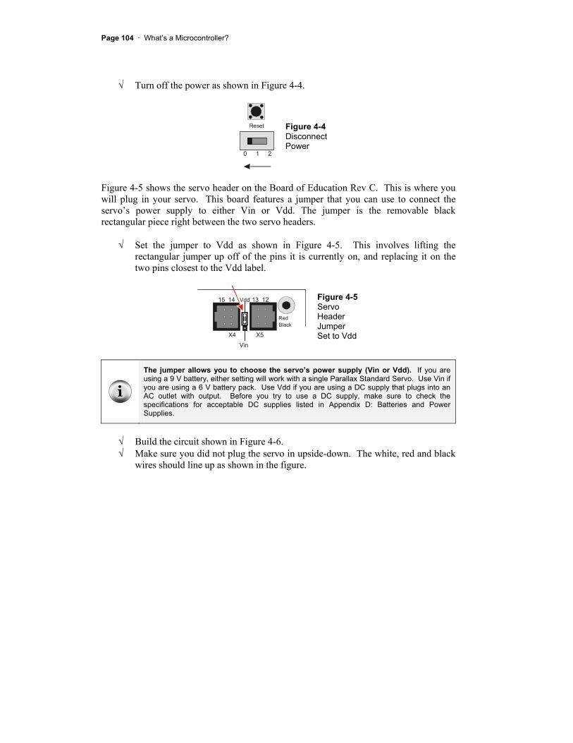
Turn off the power as shown in Figure 4-4.
Reset
0 1 2
Figure 4-4 DisconnectPower
Figure 4-5 shows the servo header on the Board of Education Rev C. This is where you will plug in your servo. This board features a jumper that you can use to connect the servo’s power supply to either Vin or Vdd. The jumper is the removable black rectangular piece right between the two servo headers.
Set the jumper to Vdd as shown in Figure 4-5. This involves lifting the rectangular jumper up off of the pins it is currently on, and replacing it on the two pins closest to the Vdd label.
BlackRed
X4 X5
15 14 13 12Vdd
Vin
Figure 4-5 ServoHeader JumperSet to Vdd
The jumper allows you to choose the servo’s power supply (Vin or Vdd). If you are using a 9 V battery, either setting will work with a single Parallax Standard Servo. Use Vin if you are using a 6 V battery pack. Use Vdd if you are using a DC supply that plugs into an AC outlet with output. Before you try to use a DC supply, make sure to check the specifications for acceptable DC supplies listed in Appendix D: Batteries and Power Supplies.
Build the circuit shown in Figure 4-6. Make sure you did not plug the servo in upside-down. The white, red and black wires should line up as shown in the figure.

Chapter #4: Controlling Motion · Page 105
Vdd
P15
P4P3
P14P13P12P11P10P9P8P7P6P5
P2P1P0
X2
X3Vdd VssVin
BlackRed
X4 X5
15 13 1214
+
BlackRed
White
www.parallax.com
standard servo
Figure 4-6 Servo and LED Indicator on Board of Education Rev C
Up until now, you have been using the 3-position switch in the 1 position. Now, you will move it to the 2 position to turn on the power to the servo header.
Supply power to the servo header by adjusting the 3-position switch as shown in Figure 4-7. Your servo may move a bit when you connect the power.
Reset
0 1 2
Figure 4-7 Power turned on to Board of Education and Servo Header
Move on to Programming Servo Control on page 110.
BASIC Stamp HomeWork Board If you are connecting your servo to a HomeWork Board, you will need these extra parts:

Page 106 · What’s a Microcontroller?
(1) 3-pin male/male header (shown in Figure 4-8). (4) Jumper wires
Figure 4-8 HomeWork Board or Board of Education – Extra Parts
(1) 3-pin male/male header (top)
Figure 4-9 shows the schematic of the servo and LED circuits on the HomeWork Board. The instructions that come after this figure will show you how to safely build this circuit.
WARNING
Use only a 9 V battery when a servo is connected to the BASIC Stamp HomeWork Board. Do not use any kind of DC supply or “battery replacer” that plugs into an AC outlet. Improper use of these devices can cause the activity not to work, or even permanently damage the servo.
For best results, make sure your battery is new. If you are using a rechargeable battery, make sure it is freshly recharged. It should also be rated for 100 mAh (milliamp hours) or more. See Appendix D: Batteries and Power Supplies for more information.
Vss
P14 White
Red
BlackServo
P14
Vss
LED470
Vin Figure 4-9 Schematic for Servo and LED Indicator on HomeWork Board

Chapter #4: Controlling Motion · Page 107
Disconnect your 9 V battery from your HomeWork Board. Build the LED indicator and servo header circuit shown in Figure 4-10.
P15
P4P3
P14P13P12P11P10P9P8P7P6P5
P2P1P0
X2
X3Vdd VssVin
+
www.parallax.com
standard servo
Figure 4-10 LED Indicator and Servo Header Circuits on HomeWork Board
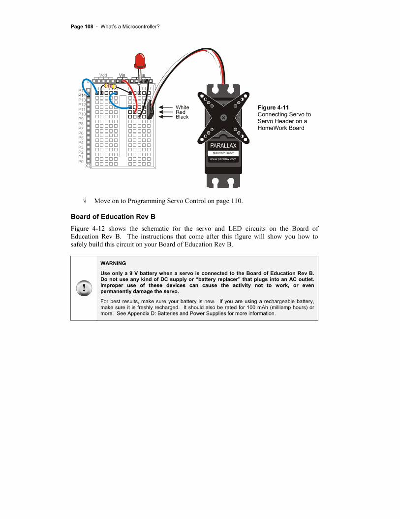
Connect the servo to the servo header as shown in Figure 4-11. Make sure that the colors on the servo’s cable align properly with the colors labeled in the picture. Double check your wiring. Reconnect your 9 V battery to your HomeWork Board. The servo may move a bit when you make the connection.
Page 108 · What’s a Microcontroller?
P15
P4P3
P14P13P12P11P10P9P8P7P6P5
P2P1P0
X2
X3Vdd VssVin
+
BlackRedWhite
www.parallax.com
standard servo
Figure 4-11 Connecting Servo to Servo Header on a HomeWork Board
Move on to Programming Servo Control on page 110.
Board of Education Rev B Figure 4-12 shows the schematic for the servo and LED circuits on the Board of Education Rev B. The instructions that come after this figure will show you how to safely build this circuit on your Board of Education Rev B.
WARNING
Use only a 9 V battery when a servo is connected to the Board of Education Rev B. Do not use any kind of DC supply or “battery replacer” that plugs into an AC outlet. Improper use of these devices can cause the activity not to work, or even permanently damage the servo.
For best results, make sure your battery is new. If you are using a rechargeable battery, make sure it is freshly recharged. It should also be rated for 100 mAh (milliamp hours) or more. See Appendix D: Batteries and Power Supplies for more information.

Chapter #4: Controlling Motion · Page 109
Vss
P14 White
Red
BlackServo
P14
Vss
LED470
VinFigure 4-12 Schematic for Servo and LED Indicator on Board of Education Rev B
Disconnect your battery or any other power supply from your board. Build the LED circuit shown in Figure 4-12. Connect the servo to the servo header as shown in Figure 4-13.
Page 110 · What’s a Microcontroller?
P15
P4P3
P14P13P12P11P10P9P8P7P6P5
P2P1P0
X2
X3Vdd VssVin
BlackRed
X4 X5
15 13 1214
+
BlackRed
White
www.parallax.com
standard servo
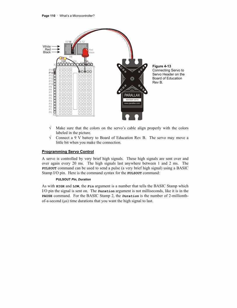
Figure 4-13 Connecting Servo to Servo Header on the Board of Education Rev B.
Make sure that the colors on the servo’s cable align properly with the colors labeled in the picture. Connect a 9 V battery to Board of Education Rev B. The servo may move a little bit when you make the connection.
Programming Servo Control
A servo is controlled by very brief high signals. These high signals are sent over and over again every 20 ms. The high signals last anywhere between 1 and 2 ms. The PULSOUT command can be used to send a pulse (a very brief high signal) using a BASIC Stamp I/O pin. Here is the command syntax for the PULSOUT command:
PULSOUT Pin, Duration
As with HIGH and LOW, the Pin argument is a number that tells the BASIC Stamp which I/O pin the signal is sent on. The Duration argument is not milliseconds, like it is in the PAUSE command. For the BASIC Stamp 2, the Duration is the number of 2-millionth-of-a-second ( s) time durations that you want the high signal to last.

Chapter #4: Controlling Motion · Page 111
A millionth of a second is called a microsecond. The Greek letter is used in place of the word micro and the letter s is used in place of second. This is handy for writing and taking notes, because instead of writing 2 microseconds, you can write 2 s.
Reminder: one thousandth of a second is called a millisecond, and is abbreviated ms.
Fact: 1 ms = 1000 s. In other words, you can fit one thousand millionths of a second into one thousandth of a second.
The next example program will use the PULSOUT command to deliver pulses that instruct the servo on where to position its horn. FOR…NEXT loops are used to deliver a certain number of pulses, which cause the servo to hold a position for a certain amount of time.
Example Program: ServoTest.bs2
ServoTest.bs2 will make the servo’s horn start at somewhere in the neighborhood of 10 o’clock and hold that position for about three seconds. Then, the program will move the servo horn clockwise, to about the 2 o’clock position for about three seconds. After that, the servo will hold its “center position”, which is about 12 o’clock, for about three seconds.
www.parallax.com
standard servo
www.parallax.com
standard servo
www.parallax.com
standard servo
Figure 4-14 Servo Horn Motion
10 o’clock (left) 2 o’clock (middle) 12 o’clock (right)
What if my servo is different? There are lots of different servos, and many will respond differently to the signals that TestServo.bs2 sends. Your servo might only rotate to 11 o’clock then 1 o’clock, or maybe to 9 o’clock and then 3 o’clock. It might even rotate the opposite direction and start in the clockwise direction before it goes counterclockwise. As long as the motion is easy to observe and consistent, it will work fine for these activities. You can always modify the example programs to get the servo to behave the way you want.
Load ServoTest.bs2 into the BASIC Stamp Editor. Connect power to your Board of Education or HomeWork Board. Run the program. Observe the servo turns at each of the three steps in the program, and record where the horn is really pointing.

Page 112 · What’s a Microcontroller?
Re-run the program and verify that the LED flickers dimly. It should be brightest when the BASIC Stamp sends the 10 o’clock signal and dimmest when the BASIC Stamp sends the 2 o’clock signal. This is because the LED circuit is only on for half as long (1 out of 21 ms instead of 2 out of 22 ms).
' What's a Microcontroller - ServoTest.bs2 ' Test the servo at three different position signals.
' {$STAMP BS2} ' {$PBASIC 2.5}
counter VAR Word
DEBUG "Counterclockwise 10 o'clock", CR
FOR counter = 1 TO 150 PULSOUT 14, 1000 PAUSE 20 NEXT
DEBUG "Clockwise 2 o'clock", CR
FOR counter = 1 TO 150 PULSOUT 14, 500 PAUSE 20 NEXT
DEBUG "Center 12 o'clock", CR
FOR counter = 1 TO 150 PULSOUT 14, 750 PAUSE 20 NEXT
DEBUG "All done."
END
How ServoTest.bs2 Works
The first FOR…NEXT loop delivers 150 pulses, each of which lasts 2.0 ms. These pulses instruct the servo to go to a position that is roughly 10 o’clock if you think about it in terms of a clock face.
FOR counter = 1 TO 150 PULSOUT 14, 1000 PAUSE 20 NEXT

Chapter #4: Controlling Motion · Page 113
PULSOUT 14, 1000 sends a pulse that lasts 1000 × 2 s. That’s 2000 s or 2 ms.
Figure 4-15 is called a timing diagram. It shows a picture of the high and low signals and how long they last. The timing diagram does not show how many pulses are delivered, but it does give you information about how long the high and low signals last. Each pulse (high signal) lasts for 2.0 ms. Each pulse is separated by a 20 ms delay while the signal is low.
Vdd (5 V)
Vss (0 V)
2.0 ms 2.0 ms
20 ms
www.parallax.com
standard servo
Figure 4-15 Timing Diagram for 2.0 ms Pulses Every 20 ms
Servo horn in 10 o’clock position.
The second FOR…NEXT loop delivers 150 pulses, but this time, each pulse only lasts 1.0 ms. This instructs the servo to turn to the 2 o’clock position for about 3.15 seconds.
FOR COUNTER = 1 TO 150 PULSOUT 14, 500 PAUSE 20 NEXT
PULSOUT 14, 500 sends a pulse that lasts 500 × 2 s. That’s 1000 s or 1 ms.
Figure 4-15 shows the timing diagram for this pulse train. The pauses between pulses still last 20 ms.
Page 114 · What’s a Microcontroller?
Vdd (5 V)
Vss (0 V)
1.0 ms 1.0 ms
20 ms
www.parallax.com
standard servo
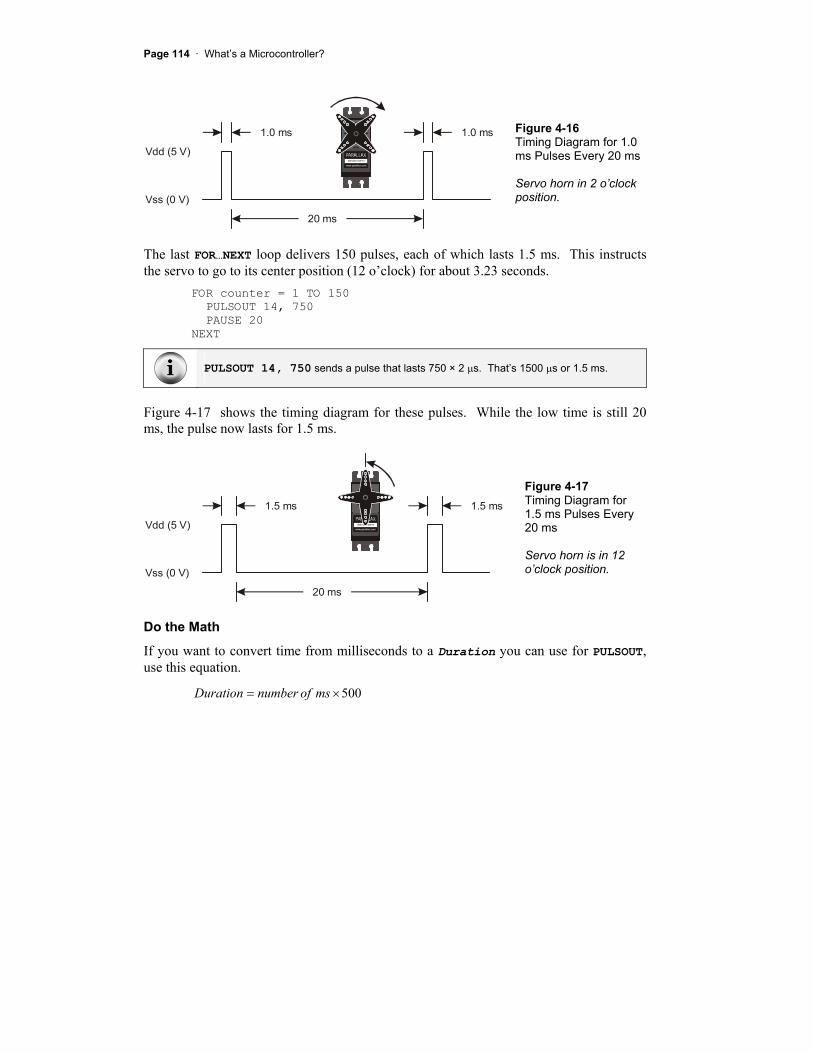
Figure 4-16 Timing Diagram for 1.0 ms Pulses Every 20 ms
Servo horn in 2 o’clock position.
The last FOR…NEXT loop delivers 150 pulses, each of which lasts 1.5 ms. This instructs the servo to go to its center position (12 o’clock) for about 3.23 seconds.
FOR counter = 1 TO 150 PULSOUT 14, 750 PAUSE 20 NEXT
PULSOUT 14, 750 sends a pulse that lasts 750 × 2 s. That’s 1500 s or 1.5 ms.
Figure 4-17 shows the timing diagram for these pulses. While the low time is still 20 ms, the pulse now lasts for 1.5 ms.
Vdd (5 V)
Vss (0 V)
1.5 ms 1.5 ms
20 ms
www.parallax.com
standard servo
Figure 4-17 Timing Diagram for 1.5 ms Pulses Every 20 ms
Servo horn is in 12 o’clock position.
Do the Math
If you want to convert time from milliseconds to a Duration you can use for PULSOUT,use this equation.
500msofnumberDuration

Chapter #4: Controlling Motion · Page 115
For example, if you didn’t already know that the PULSOUT argument for 1.5 ms is 750, here is how you could calculate it.
7505005.1Duration
You can also figure out the Duration of a mystery PULSOUT command using this equation.
msDurationmsofnumber500
For example, if you see the command PULSOUT 14, 850, how long does that pulse really last?
ms
msmsofnumber
7.1500850
Your Turn – Adjusting Position and Hold Time
The number of times each FOR…NEXT loop repeats is what controls how long the servo stays in a given position. The value of the PULSOUT command’s Duration argument controls where the servo turns to. It’s important to experiment with changing these values to be sure how they work before moving on to the next experiment.
Save ServoTest.bs2 as ServoTestYourTurn.bs2. Modify all the FOR...NEXT loops so that they execute half as many times as the original program: FOR counter = 1 to 75
Run the modified program and verify that the servo holds each position for half as long. Modify all the FOR...NEXT loops so that they execute twice as many times as the original program: FOR counter = 1 to 300
Run the modified program and verify that the servo holds each position for twice as long. Modify the PULSOUT command in the first loop so that it reads:
Page 116 · What’s a Microcontroller?
PULSOUT 14,850
Modify the PULSOUT command in the second loop so that it reads: PULSOUT 14,650
Run the modified program, and explain the differences in the positions the servo turns to and holds.
ACTIVITY #2: CONTROLLING POSITION WITH YOUR COMPUTER Factory automation often involves microcontrollers communicating with larger computers. The microcontrollers read sensors and transmit that data to the main computer. The main computer interprets and analyzes the sensor data, then sends position information back to the microcontroller. The microcontroller might then update a conveyer belt’s speed, or a sorter’s position, or some other mechanical, motor controlled task.
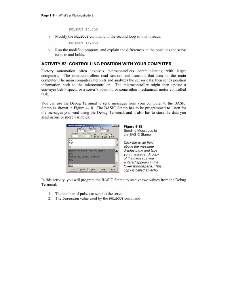
You can use the Debug Terminal to send messages from your computer to the BASIC Stamp as shown in Figure 4-18. The BASIC Stamp has to be programmed to listen for the messages you send using the Debug Terminal, and it also has to store the data you send in one or more variables.
Figure 4-18 Sending Messages to the BASIC Stamp
Click the white field above the message display pane and type your message. A copy of the message you entered appears in the lower windowpane. This copy is called an echo.
In this activity, you will program the BASIC Stamp to receive two values from the Debug Terminal:
1. The number of pulses to send to the servo 2. The Duration value used by the PULSOUT command
Chapter #4: Controlling Motion · Page 117
You will also program the BASIC Stamp to use these values to control the servo.
Parts and Circuit
Same as Activity #1
Programming the BASIC Stamp to Receive Messages from Debug
Programming the BASIC Stamp to send messages to the Debug Terminal is done using the DEBUG command. Programming the BASIC Stamp to receive messages from the Debug Terminal is done using the DEBUGIN command. When using this command, you also have to declare one or more variables for the BASIC Stamp to store the information it receives. Here is an example of a variable you can declare for the BASIC Stamp to store a value:
pulses VAR Word
Later in the program, you can use this value to store a number received by the DEBUGINcommand:
DEBUGIN DEC pulses
When the BASIC Stamp receives a numeric value from the Debug Terminal, it will store it in the pulses variable. The DEC formatter tells the DEBUGIN command that the characters you are sending will be digits that form a decimal number. As soon as you hit the carriage return, the BASIC Stamp will store the digits it received in the pulsesvariable as a decimal number, then move on.
Although it is not included in the example program, you can add a line to verify that the message was processed by the BASIC Stamp.
DEBUG CR, "You sent the value: ", DEC pulses
Example Program: ServoControlWithDebug.bs2
Figure 4-19 shows a close-up view of the Transmit Windowpane in the Debug Terminal. Your Transmit Windowpane may be smaller. You can click and drag the separator between the two panes downward to make the Transmit Windowpane larger. You can type characters into the Transmit Windowpane to send them to the BASIC Stamp. In this example, somebody typed in 100, then hit the carriage return, then typed in 850. The Receive Windowpane displays the “Enter number of pulses:” message sent by the BASIC Stamp. It also displays an echo of the characters 100 that were typed into the Transmit Windowpane.

Page 118 · What’s a Microcontroller?
Figure 4-19 Debug Terminal’s Windowpanes:
Transmit Windowpane
Receive Windowpane
Echo is when you send a message, and a copy of that message appears in your Receive Windowpane. You can click the Echo Off checkbox (shown below) to make a checkmark appear in it. This will make the Debug Terminal stop displaying these echoes.
Enter ServoControlWithDebug.bs2 into the BASIC Stamp Editor and run it. If the Transmit Windowpane is too small, resize it using your mouse to click, hold, and drag the separator downward. The separator is shown just above the text message: “Enter number of pulses:” in Figure 4-19. Click the upper, Transmit Windowpane to place your cursor there for typing messages. When the Debug Terminal prompts you to, “Enter number of pulses:”, type the number 100, then press enter. When the Debug Terminal prompts you to “Enter PULSOUT duration:” type the number 850, then press enter.
The PULSOUT Duration should be a number between 500 and 1000. If you enter numbers outside that range, the servo may try to rotate to a position beyond its own mechanical limits. Although it will not break the servo, it could shorten the device’s lifespan.
The BASIC Stamp will display the message “Servo is running…” while it is sending pulses to the servo. When it is done sending pulses to the servo, it will display the message “Done” for one second. Then, it will prompt you to enter the number of pulses again. Have fun with it, but make sure to follow the directive in the caution box about staying between 500 and 1000 for your PULSOUT value.

Chapter #4: Controlling Motion · Page 119
Experiment with entering other values between 500 and 1000 for the PULSOUTDuration and values between 1 and 65534 for the number of pulses.
It takes between 40 and 45 pulses to make the servo hold a position for 1 second.
' What's a Microcontroller - ServoControlWithDebug.bs2 ' Send messages to the BASIC Stamp to control a servo using ' the Debug Terminal.
' {$STAMP BS2} ' {$PBASIC 2.5}
counter Var Word pulses Var Word duration Var Word
DO
DEBUG CLS, "Enter number of pulses:", CR DEBUGIN DEC pulses
DEBUG "Enter PULSOUT duration:", CR DEBUGIN DEC duration
DEBUG "Servo is running...", CR
FOR counter = 1 TO pulses PULSOUT 14, duration PAUSE 20 NEXT
DEBUG "DONE" PAUSE 1000
LOOP
How ServoControlWithDebug.bs2 Works
Three Word variables are declared in this program:
counter Var WORD pulses Var WORD duration Var WORD

Page 120 · What’s a Microcontroller?
The counter variable is declared for use by a FOR…NEXT loop. See Chapter #2, Activity #3 for details. The pulses and duration variables are used a couple of different ways. They are both used to receive and store values sent from the Debug Terminal. The pulses variable is also used to set the number of repetitions in the FOR…NEXT loop that delivers pulses to the servo, and the duration variable is used to set the duration for the PULSOUT command.
The rest of the program is nested inside a DO…LOOP without a WHILE or UNTIL argument so that the commands execute over and over again.
DO ' Rest of program not shown. LOOP
The DEBUG command is used to send you (the “user” of the software) a message to enter the number of pulses. Then, the DEBUGIN command waits for you to enter digits that make up the number and press the Enter key on your keyboard. The digits that you enter are converted to a value that is stored in the pulses variable. This process is repeated with a second DEBUG and DEBUGIN command that loads a value into the durationvariable too.
DEBUG CLS, "Enter number of pulses:", CR DEBUGIN DEC pulses
DEBUG "Enter PULSOUT duration:", CR DEBUGIN DEC duration
After you enter the second value, it’s useful to display a message while the servo is running so that you don’t try to enter a second value:
DEBUG "Servo is running...", CR
While the servo is running, you can gently try to move the servo horn away from the position it is holding. The servo resists light pressure applied to the horn.
FOR Counter = StartValue TO EndValue {STEP StepValue}…NEXT
This is the FOR…NEXT loop syntax from the BASIC Stamp Manual. It shows that you need a Counter, StartValue and EndValue to control how many times the loop repeats itself. There is also an optional StepValue if you want to add a number other than 1 to the value of Counter each time through the loop.

Chapter #4: Controlling Motion · Page 121
As in previous examples, the counter variable is used as an index for the FOR…NEXTloop. Up until this example, all the FOR…NEXT loops have used constants such as 10 or 150 for EndValue. In this FOR…NEXT loop, the value of the pulses variable is used to control the EndValue of the FOR…NEXT loop. This, in turn, controls how many pulses are delivered to the servo. The end result is that the pulses variable controls how long the servo holds a given position. Up until now, constant values such as 500, 750, and 1000 were also used for the PULSOUT command’s Duration argument. Look carefully at this FOR…NEXT loop to see where and how these variables are used:
FOR counter = 1 to pulses PULSOUT 14, duration PAUSE 20 NEXT
Take some time to understand this FOR…NEXT loop. It is one of the first examples of the amazing things you can do with variables in PBASIC command arguments, and it also highlights how useful a programmable microcontroller like the BASIC Stamp can be.
Your Turn – Setting Limits in Software
The example program doesn’t stop you or anybody else from entering a PULSOUT duration such as 1500, which is not good for the servo. This is a problem that needs to be fixed if you are designing this system into a product.
Let’s imagine that this computer servo control system is one that has been developed for remote-controlling a door. Perhaps a security guard will use this to open a shipping door that he or she watches on a remote camera. Maybe a college student will use it to control doors in a maze that mice navigate in search of food. Maybe a military gunner will use it to point the cannon at a particular target. If you are designing the product for somebody else to use, the last thing you want is to give the user (security guard, college student, military gunner) the ability to enter the wrong number and damage the equipment.
To fix this problem, try this:
Save the example program ServoControlWithDebug.bs2 under the new name ServoControlWithDebugYourTurn.bs2. Replace these two commands: DEBUG "Enter pulsout duration:", CR DEBUGIN DEC duration

Page 122 · What’s a Microcontroller?
with this code block: DO DEBUG "Enter pulsout duration:", CR DEBUGIN DEC duration IF duration < 500 THEN DEBUG "Value of duration must be above 499", CR PAUSE 1000 ENDIF IF duration > 1000 THEN DEBUG "Value of duration must be below 1001", CR PAUSE 1000 ENDIF LOOP UNTIL duration > 499 AND duration < 1001
Save the program. Run the program and verify that it rejects values outside the appropriate range for the servo.
ACTIVITY #3: CONVERTING POSITION TO MOTION In this activity, you will program the servo to change position at different rates. By changing position at different rates, you will cause your servo horn to rotate at different speeds. You can use this technique to make the servo control motion instead of position.
Programming a Rate of Change for Position
You can use a FOR…NEXT loop to make a servo sweep through its range of motion like this:
FOR counter = 500 TO 1000 PULSOUT 14, counter PAUSE 20 NEXT
The FOR…NEXT loop causes the servo’s horn to start at around 2 o’clock and then rotate slowly counterclockwise until it gets to 10 o’clock. Because counter is the index of the FOR…NEXT loop, it increases by one each time through. The value of counter is also used in the PULSOUT command’s Duration argument, which means the duration of each pulse gets a little longer each time through the loop. Since the duration changes, so does the position of the servo’s horn.
FOR…NEXT loops have an optional STEP argument. The STEP argument can be used to make the servo rotate faster. For example, you can use the STEP argument to add 8 to
Chapter #4: Controlling Motion · Page 123
counter each time through the loop (instead of 1) by modifying the FOR statement like this:
FOR counter = 500 TO 1000 STEP 8
You can also make the servo turn the opposite direction by counting down instead of counting up. In PBASIC, FOR…NEXT loops will also count backwards if the StartValueargument is larger than the EndValue argument. Here is an example of how to make a FOR…NEXT loop count from 1000 to 500:
FOR counter = 1000 TO 500
You can combine counting down with a STEP argument to get the servo to rotate more quickly in the clockwise direction like this:
FOR counter = 1000 TO 500 STEP 20
The trick to getting the servo to turn at different rates is to use these FOR…NEXT loops to count up and down with different step sizes. The next example program uses these techniques to make the servo’s horn rotate back and forth at different rates.
Example Program: ServoVelocities.bs2
Load and run the program. As the program runs, watch how the value of counter changes in the Debug Terminal. Also, watch how the servo behaves differently through the two different FOR…NEXT loops. Both the servo’s direction and speed change.
' What's a Microcontroller - ServoVelocities.bs2 ' Rotate the servo counterclockwise slowly, then clockwise rapidly.
' {$STAMP BS2} ' {$PBASIC 2.5}
counter VAR Word
DO
DEBUG "Pulse width increment by 8", CR
FOR counter = 500 TO 1000 STEP 8 PULSOUT 14, counter PAUSE 7 DEBUG DEC5 counter, CR, CRSRUP NEXT

Page 124 · What’s a Microcontroller?
DEBUG CR, "Pulse width decrement by 20", CR
FOR counter = 1000 TO 500 STEP 20 PULSOUT 14, counter PAUSE 7 DEBUG DEC5 counter, CR, CRSRUP NEXT
DEBUG CR, "Repeat", CR
LOOP
How ServoVelocities.bs2 Works
The first FOR…NEXT loop counts upwards from 500 to 1000 in steps of 8. Since the counter variable is used as the PULSOUT command’s Duration argument, the servo horn’s position rotates counterclockwise by steps that are eight times the smallest possiblestep.
FOR counter = 500 TO 1000 STEP 8 PULSOUT 14, counter PAUSE 7 DEBUG DEC5 counter, CR, CRSRUP NEXT
Why PAUSE 7 instead of PAUSE 20? The command DEBUG DEC5 counter, CR, CRSRUP takes about 8 ms to execute. This means that PAUSE 12 would maintain the 20 ms delay between pulses. A few trial and error experiments showed that PAUSE 7gave the servo the smoothest motion. Your servo may be different.
More DEBUG formatters and control characters are featured in the DEBUG command that displays the value of the counter variable. This value is printed using the 5-digit decimal format (DEC5). After the value is printed, there is a carriage return (CR). After the carriage return, the formatter CRSRUP (cursor up) sends the cursor back up to the previous line. This causes the new value of counter to be printed over the old value each time through the loop.
The second FOR…NEXT loop counts downwards from 1000 back to 500 in steps of 20. The counter variable is also used as an argument for the PULSOUT command in this example, so the servo horn rotates clockwise.
FOR counter = 1000 TO 500 STEP 20 PULSOUT 14, counter
Chapter #4: Controlling Motion · Page 125
PAUSE 7 DEBUG DEC5 counter, CR, CRSRUP NEXT
Your Turn – Adjusting the Velocities
Try different STEP values to make the servo turn at different rates. Re-run the program after each modification. Observe the effect of each new STEP value on how fast the servo horn turns. Experiment with different PAUSE command Duration values (between 3 and 12) to find the value that gives the servo the smoothest motion for each new STEPvalue.
ACTIVITY #4: PUSHBUTTON CONTROLLED SERVO In this chapter, you have written programs that make the servo go through a pre-recorded set of motions, and you have controlled the servo using the Debug Terminal. You can also program the BASIC Stamp to control the servo based on pushbutton inputs. In this activity you will:
Build a circuit for a pushbutton controlled servo. Program the BASIC Stamp to control the servo based on the pushbutton inputs.
When you are done, you will be able to push one button to get the BASIC Stamp to rotate the servo in one direction, and another button to get the servo to rotate in the other direction. When no buttons are pressed, the servo will hold whatever position it moved to.
Extra Parts for Pushbutton Servo Control
The same parts from the previous activities in this chapter are still used. You will need to gather the following parts for the pushbutton circuits:
(2) Pushbuttons – normally open (2) Resistors – 10 k (brown-black-orange) (2) Resistors – 220 (red-red-brown) (3) Jumper wires

Page 126 · What’s a Microcontroller?
Adding the Pushbutton Control Circuit
Figure 4-20 shows the pushbutton circuits that you will use to control the servo.
Vdd Vdd
10 k
Vss
10 k
Vss
P4
P3
220
220
Figure 4-20 Pushbutton Circuits for Servo Control
Add this circuit to the servo+LED circuit that you have been using up to this point. When you are done your circuit should resemble:
Figure 4-21 if you are using the Board of Education Rev C Figure 4-22 if you are using the HomeWork Board Figure 4-23 if you are using the Board of Education Rev B

Chapter #4: Controlling Motion · Page 127
Vdd
P15P14
P4P3
P13P12P11P10P9P8P7P6P5
P2P1P0
X2
X3Vdd VssVin
BlackRed
X4 X5
15 13 1214
+
www.parallax.com
standard servo
BlackRed
White
Figure 4-21 Board of Education Rev C Servo Circuit with Pushbutton Circuits Added
P15
P4P3
P14P13P12P11P10P9P8P7P6P5
P2P1P0
X2
X3Vdd VssVin
+
BlackRedWhite
www.parallax.com
standard servo
Figure 4-22 HomeWork Board Servo Circuit with Pushbutton Circuits Added

Page 128 · What’s a Microcontroller?
P15
P4P3
P14P13P12P11P10P9P8P7P6P5
P2P1P0
X2
X3Vdd VssVin
BlackRed
X4 X5
15 13 1214
+
BlackRed
White
www.parallax.com
standard servo
Figure 4-23 Board of Education Rev B Servo Circuit with Pushbutton Circuits Added
Test the pushbutton connected to P3 using the original version of ReadPushbuttonState.bs2. The section that has this program and the instructions on how to use it begins on page 77. Modify the program so that it reads P4. Run the modified program to test the pushbutton connected to P4.
Programming Pushbutton Servo Control
Pushbutton servo control is not much different from pushbutton LED control. IF…THENcode blocks are used to check the pushbutton states and either add or subtract from a variable called duration. This variable is used in the PULSOUT command’s Durationargument. If one of the pushbuttons is pressed, the value of duration increases. If the other pushbutton is pressed, the value of duration decreases. A nested IF…THENstatement is used to decide if the duration variable is too large (greater than 1000) or too small (smaller than 500).
Chapter #4: Controlling Motion · Page 129
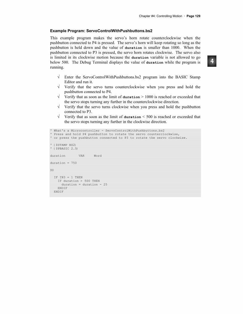
Example Program: ServoControlWithPushbuttons.bs2
This example program makes the servo’s horn rotate counterclockwise when the pushbutton connected to P4 is pressed. The servo’s horn will keep rotating so long as the pushbutton is held down and the value of duration is smaller than 1000. When the pushbutton connected to P3 is pressed, the servo horn rotates clockwise. The servo also is limited in its clockwise motion because the duration variable is not allowed to go below 500. The Debug Terminal displays the value of duration while the program is running.
Enter the ServoControlWithPushbuttons.bs2 program into the BASIC Stamp Editor and run it. Verify that the servo turns counterclockwise when you press and hold the pushbutton connected to P4. Verify that as soon as the limit of duration > 1000 is reached or exceeded that the servo stops turning any further in the counterclockwise direction. Verify that the servo turns clockwise when you press and hold the pushbutton connected to P3. Verify that as soon as the limit of duration < 500 is reached or exceeded that the servo stops turning any further in the clockwise direction.
' What's a Microcontroller - ServoControlWithPushbuttons.bs2 ' Press and hold P4 pushbutton to rotate the servo counterclockwise, ' or press the pushbutton connected to P3 to rotate the servo clockwise.
' {$STAMP BS2} ' {$PBASIC 2.5}
duration VAR Word
duration = 750
DO
IF IN3 = 1 THEN IF duration > 500 THEN duration = duration - 25 ENDIF ENDIF

Page 130 · What’s a Microcontroller?
IF IN4 = 1 THEN IF duration < 1000 THEN duration = duration + 25 ENDIF ENDIF
PULSOUT 14, duration PAUSE 10
DEBUG HOME, DEC4 duration, " = duration"
LOOP
Your Turn – Software Stoppers
Servos have a built in mechanical stopper that prevents them from turning too far. If you try to send a command like PULSOUT 14, 2000, the servo will not turn to a position that corresponds to a Duration argument of 2000. This is because servos have built-in mechanical stoppers that limit the range of motion. By gently turning the horn, you can feel when the servo’s internal gears run into this mechanical stopper. You can modify the example program in this activity so that the BASIC Stamp limits the servo’s motion to a range that is narrower than the limits imposed by the mechanical stoppers.
Save ServoControlWithPushbuttons.bs2 under a new name. Adjust the software limits imposed on the servo’s motion so that they are 650 and 850 instead of 500 and 1000. Adjust the software imposed rate so that the duration variable is incremented or decremented by 10 instead of 25. Decide what differences you expect to see in the way the servo behaves when you press the pushbutton. Run the program and compare the actual results with your expected results.
Chapter #4: Controlling Motion · Page 131
SUMMARY This chapter introduced microcontrolled motion using a servo. A servo is a device that moves to and holds a particular position based on electronic signals it receives. These signals take the form of pulses that last anywhere between 1 and 2 ms, and they have to be delivered every 20 ms for the servo to maintain its position.
A programmer can use the PULSOUT command to make the BASIC Stamp send these signals. Since pulses have to be delivered every 20 ms for the servo to hold its position, the PULSOUT and PAUSE commands are usually placed in some kind of loop. Variables can be used to store the value used in the PULSOUT command’s Duration argument. This causes the servo’s horn to rotate in steps.
In this chapter, a variety of ways to get the values into the variables were presented. The variable can receive the value from your Debug Terminal using the DEBUGIN command. The value of the variable can pass through a sequence of values if the same variable is used as the index for a FOR…NEXT loop. This technique can be used to cause the servo to make sweeping motions. IF…THEN statements can be used to monitor pushbuttons and add or subtract from the variable used in the PULSOUT command’s Duration argument based on whether or not a certain button is pressed. This allows both position control and sweeping motions depending on how the program is constructed and how the pushbuttons are operated.
Questions
1. What appliances or tools have you relied on in the last week that might contain a microcontroller that controls motion?
2. What are the four external parts on a servo? What are they used for? 3. Is an LED circuit required to make a servo work? 4. What command controls the low time in the signal sent to a servo? What
command controls the high time? 5. What programming element can you use to control the amount of time that a
servo holds a particular position? 6. What command really controls the position of the servo? What is the name of
the argument in the command that, if changed, will cause the servo’s position to change?
7. When a servo is under BASIC Stamp control, what does the LED’s brightness tell you about the signal it is sending to the servo?

Page 132 · What’s a Microcontroller?
8. How do you use the Debug Terminal to send messages to the BASIC Stamp? What programming command is used to make the BASIC Stamp receive messages from the Debug Terminal?
9. If the user is sending messages that tell the servo what position to turn to, what kind of code block is helpful to make sure that he/she does not enter a number that is too large or too small?
10. What’s the name of the argument used to make a FOR…NEXT loop add or subtract a value greater than 1 each time through the loop? How do you make a FOR…NEXT loop count backwards?
11. What does the servo do if you use the index of a FOR…NEXT loop as the argument for the PULSOUT command’s Duration argument?
12. What type of code block can you write to limit the servo’s range of motion?
Exercises
1. The command PULSOUT 14, 750 delivers a 1.5 ms pulse on I/O pin P14. Calculate how long the pulse would last if the Duration argument of 750 is changed to 600. Repeat this calculation for these values: (a) 650, (b) 50000, (c) 1, (d) 2, (e) 2000.
2. Write the command required to deliver a 5.25 ms pulse on I/O pin P15. 3. Write a loop that delivers a 10.125 ms pulse on I/O pin P15 every 50 ms: (a)
indefinitely, (b) for 10 repetitions, (c) indefinitely, so long as the pushbutton connected to P3 sends a low signal, (d) for ten seconds after a press to the pushbutton connected to P4 is detected.
4. Write a code block that sweeps the value of the PULSOUT command controlling a servo from a duration of 700 to 800, then back to 700 again, in increments of (a) 1, (b) 2, (c) 3, (d) 4.
5. Add a nested FOR…NEXT loop to your answer to exercise 4 (d) so that it delivers ten pulses before incrementing the PULSOUT command’s Duration argument by 4.
Projects
1. Modify ServoControlWithDebug.bs2 so that it monitors a kill switch. When the kill switch (the pushbutton connected to P3) is being pressed by the user, the Debug Terminal should not accept any commands. It should display the message: “Press Start switch to start machinery”. When the start switch (the pushbutton connected to P4) is pressed, the program will function normally, like it does when you run the example program. If power is disconnected and

Chapter #4: Controlling Motion · Page 133
reconnected, the program should behave as though the kill switch has been pressed. OPTIONAL: Add a bi-color LED circuit connected to P12 and P13. The bi-color LED should be red after the kill switch has been pressed and green after the start switch has been pressed.
2. Design a prototype for a button-controlled windshield wiper. The windshield wiper should have six speeds. Stopped and intermittent (once every 10 seconds), are two of these speeds. The other four cause the windshield wiper to go back and forth at approximately the following speeds: once every three seconds, once every two seconds, once per second, and twice per second. The user should be able to press the pushbutton connected to P4 to make the windshield wiper go faster, and he/she should be able to press the pushbutton connected to P3 to make it go slower.
Further Investigation
The servo, and using sensors to control servos, can be investigated in detail in a variety of Stamps in Class texts.
“Advanced Robotics: with the Toddler”, Student Guide, Version 1.2, Parallax Inc., 2003
Advanced Robotics: with the Toddler uses servos to control the motions of the Parallax Toddler robot’s legs. Although we take walking for granted, programming a machine to walk, maneuver, and keep its balance can be very challenging. This walking robot is recommended for advanced students who have already mastered the concepts in What’s a Microcontroller? and either Robotics! or SumoBot.
“Robotics!”, Student Workbook, Version 1.5, Parallax Inc., 2000 Robotics! makes use of the same servo control principles you just learned with a twist; servos can also be modified and used as rolling robot motors. Using the BASIC Stamp, Board of Education, and Robotics! kit, this text starts with the basics of robot navigation, then guides you through navigation with sensors. It also introduces some more in-depth topics such as solving problems with artificial intelligence and navigation using elementary control systems.
“SumoBot”, Student Workbook, Version 1.1, Parallax Inc., 2002 Robot Sumo is a very exciting competition that is fun for observers and participants. SumoBot is a guided tour through building, testing, and competing

Page 134 · What’s a Microcontroller?
with your own autonomous Mini-Sumo class robot. This textbook offers a condensed presentation of the Robotics! text material applied towards the goal of winning a robotic sumo wrestling contest.