chapter 4 basic mechanical tests - آپلود رایگان...
TRANSCRIPT
CHAPTER
FIVE BASIC MECHANICAL TESTS
5.1. UNIAXIAL TENSION AND COMPRESSION Static tensile and compressive testing are the most fundamental tests to define material properties. Typically, the tests are carried out by increasing the uniaxial load gradually, i.e., statically, until failure occurs. Properties to be defined through testing include:
• Strengths: yield, ultimate, rupture, etc. • Strains: • Elastic modulus, • Poisson’s ratio • Elongation, and shortening • Uniaxial stress - strain relationships
5.1.1 Tensile Tests
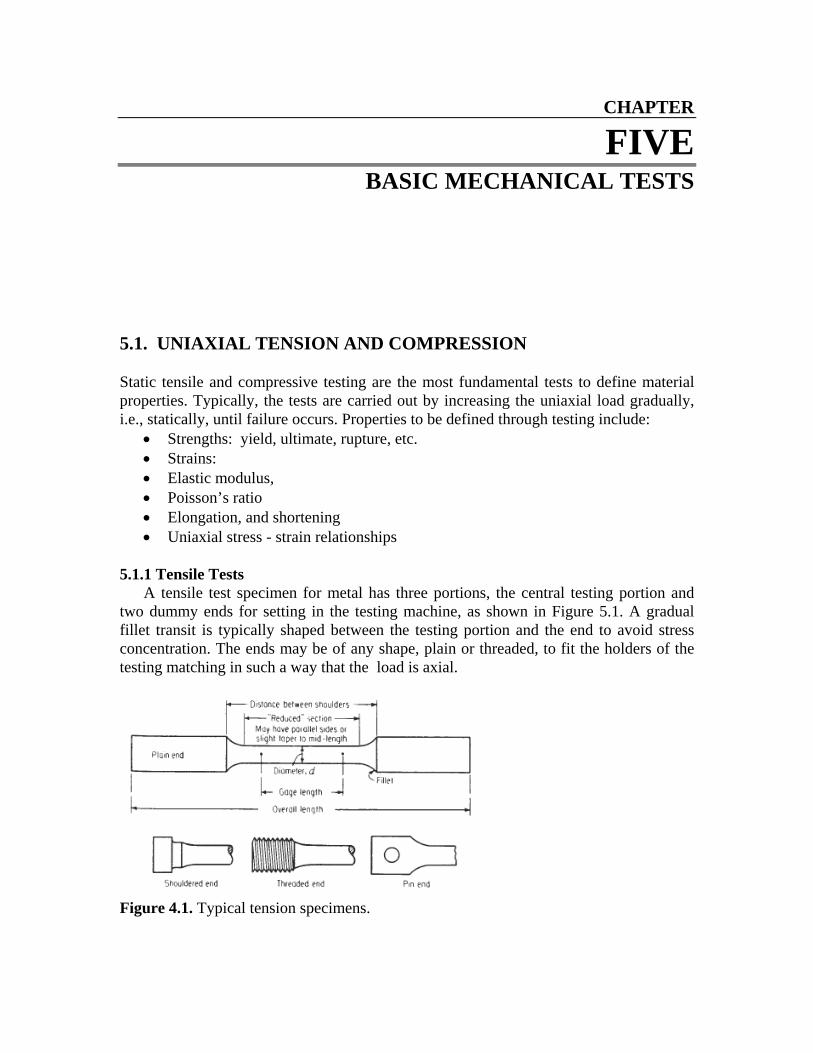
A tensile test specimen for metal has three portions, the central testing portion and two dummy ends for setting in the testing machine, as shown in Figure 5.1. A gradual fillet transit is typically shaped between the testing portion and the end to avoid stress concentration. The ends may be of any shape, plain or threaded, to fit the holders of the testing matching in such a way that the load is axial.
Figure 4.1. Typical tension specimens.
CE334 Notes, Prof. Y. Xiao Chapter 5. BASIC MECHANICAL TESTS
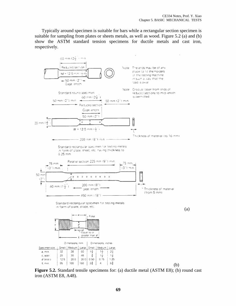
Typically around specimen is suitable for bars while a rectangular section specimen is
suitable for sampling from plates or sheets metals, as well as wood. Figure 5.2 (a) and (b) show the ASTM standard tension specimens for ductile metals and cast iron, respectively.
(a)
(b) Figure 5.2. Standard tensile specimens for: (a) ductile metal (ASTM E8); (b) round cast iron (ASTM E8, A48).
69
CE334 Notes, Prof. Y. Xiao Chapter 5. BASIC MECHANICAL TESTS
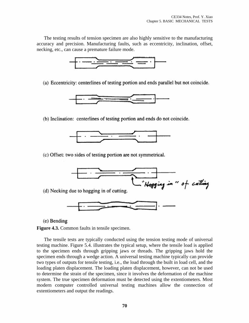
f tension specimen are also highly sensitive to the manufacturing ccuracy and precision. Manufacturing faults, such as eccentricity, inclination, offset,
nec
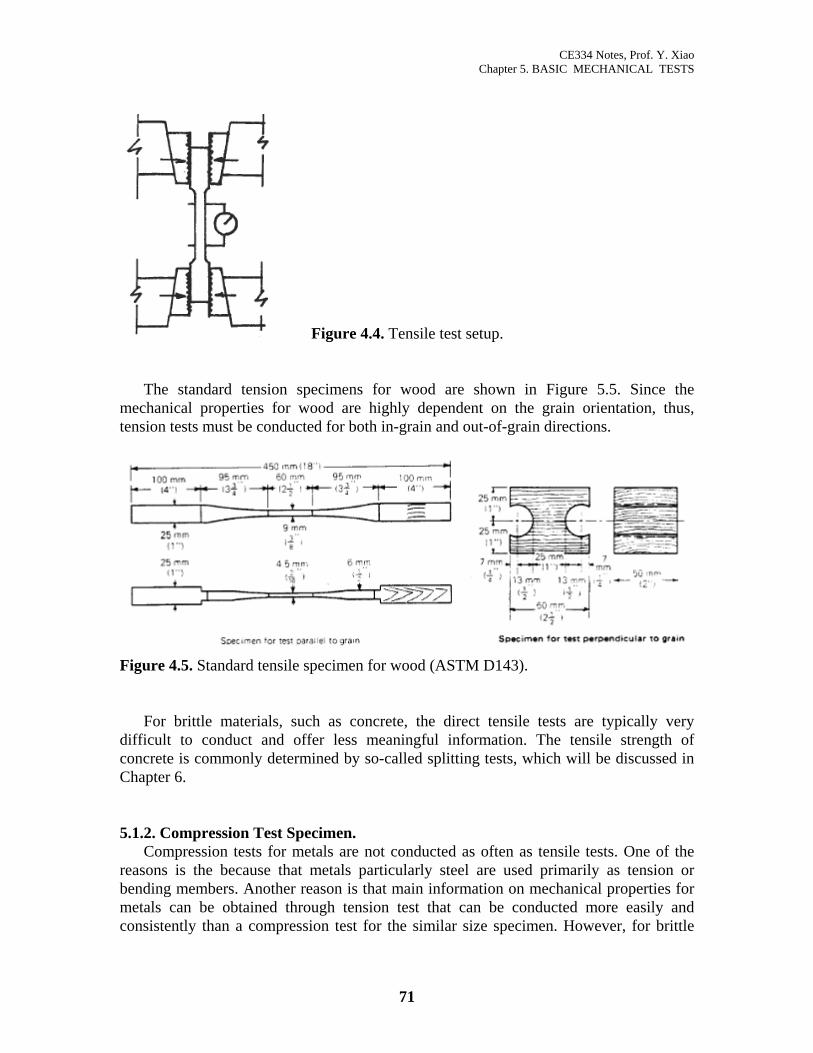
ode of universal testing machine. Figure 5.4. illustrates the typical setup, where the tensile load is applied to
The testing results o
aking, etc., can cause a premature failure mode.
Figure 4.3. Common faults in tensile specimen.
The tensile tests are typically conducted using the tension testing m
the specimen ends through gripping jaws or threads. The gripping jaws hold the specimen ends through a wedge action. A universal testing machine typically can provide two types of outputs for tensile testing, i.e., the load through the built in load cell, and the loading platen displacement. The loading platen displacement, however, can not be used to determine the strain of the specimen, since it involves the deformation of the machine system. The true specimen deformation must be detected using the extentiometers. Most modern computer controlled universal testing machines allow the connection of extentiometers and output the readings.
70
CE334 Notes, Prof. Y. Xiao Chapter 5. BASIC MECHANICAL TESTS
Figure 4.4. Tensile test setup.
The standard tension specimens for wood are shown in Figure 5.5. Since the echanical properties for wood are highly dependent on the grain orientation, thus,
tensm
ion tests must be conducted for both in-grain and out-of-grain directions.
Figure 4.5. Standard tensile specimen for wood (ASTM D143).
For brittle materials, such as concrete, the direct tensile tests are typically very ifficult to conduct and offer less meaningful information. The tensile strength of
con
.1.2. Compression Test Specimen. Compression tests for metals are not conducted as often as tensile tests. One of the
articularly steel are used primarily as tension or ben
dcrete is commonly determined by so-called splitting tests, which will be discussed in
Chapter 6. 5
reasons is the because that metals pding members. Another reason is that main information on mechanical properties for
metals can be obtained through tension test that can be conducted more easily and consistently than a compression test for the similar size specimen. However, for brittle
71
CE334 Notes, Prof. Y. Xiao Chapter 5. BASIC MECHANICAL TESTS
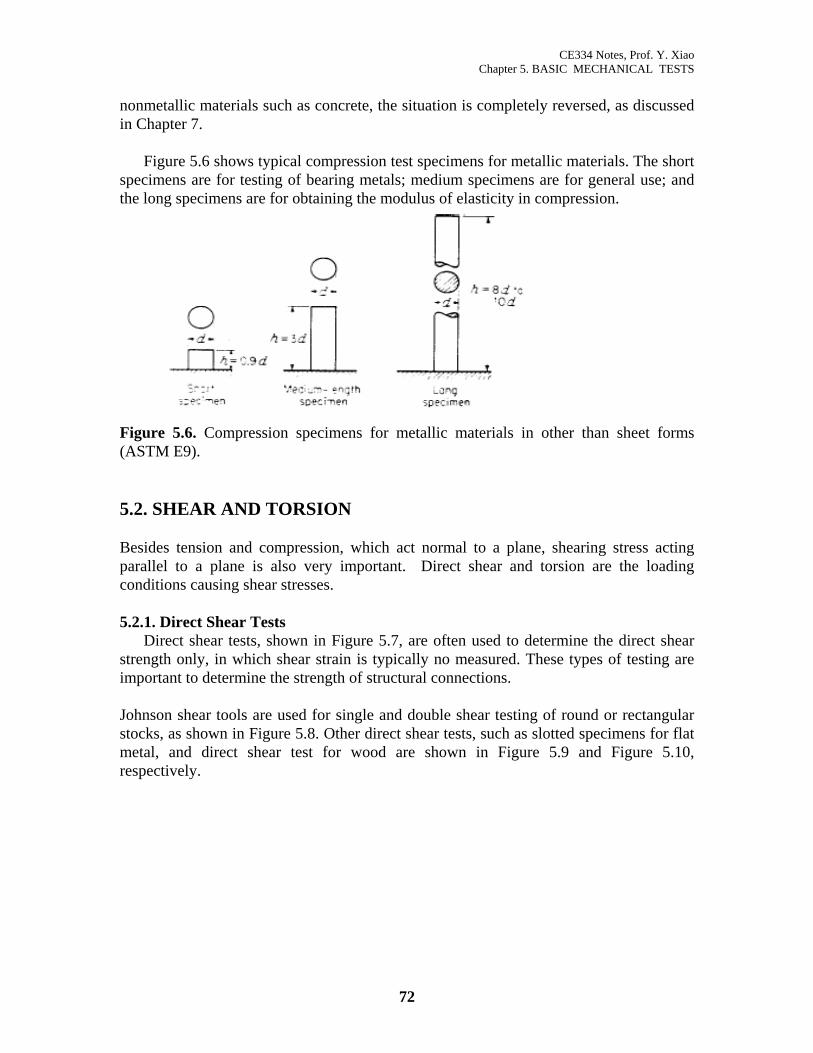
igure 5.6 shows typical compression test specimens for metallic materials. The short spe
nonmetallic materials such as concrete, the situation is completely reversed, as discussed in Chapter 7.
Fcimens are for testing of bearing metals; medium specimens are for general use; and
the long specimens are for obtaining the modulus of elasticity in compression.
Figure 5.6. Compression specimens for metallic materials in other than sheet forms
.2. SHEAR AND TORSION
esides tension and compression, which act normal to a plane, shearing stress acting
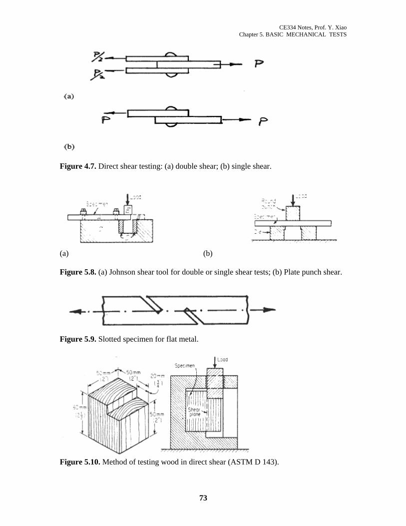
.2.1. Direct Shear Tests n in Figure 5.7, are often used to determine the direct shear
stre
Johnson shear tools are used for single and double shear testing of round or rectangular
(ASTM E9). 5 Bparallel to a plane is also very important. Direct shear and torsion are the loading conditions causing shear stresses. 5
Direct shear tests, showngth only, in which shear strain is typically no measured. These types of testing are
important to determine the strength of structural connections.
stocks, as shown in Figure 5.8. Other direct shear tests, such as slotted specimens for flat metal, and direct shear test for wood are shown in Figure 5.9 and Figure 5.10, respectively.
72
CE334 Notes, Prof. Y. Xiao Chapter 5. BASIC MECHANICAL TESTS
Figure 4.7. Direct shear testing: (a) double shear; (b) single shear.
(a) (b) Figure 5.8. (a) Johnson shear tool for double or single shear tests; (b) Plate punch shear.
Figure 5.9. Slotted specimen for flat metal.
Figure 5.10. Method of testing wood in direct shear (ASTM D 143).
73

CE334 Notes, Prof. Y. Xiao Chapter 5. BASIC MECHANICAL TESTS
5.2.2. Torsion Tests
Torsion, as shown in Figure 5.11, often exists in machinery structural members and parts. Since a pure shear stress state can be obtained, shear stain can be easily measured. Torsion test is typically used in determining shear modulus of metal.
Figure 5.11. Torsion
As shown in Figure 5.11, the following relationships exist for torsion members,
stress: τmax =TrJ
(5.1)
where, the J is the polar moment of inertia, and J = πr4/36, for circle solid.
angle of twist: ϕ =TLJG
(5.2)
Direct torsion test is typically conducted using torsion testing machine, which is
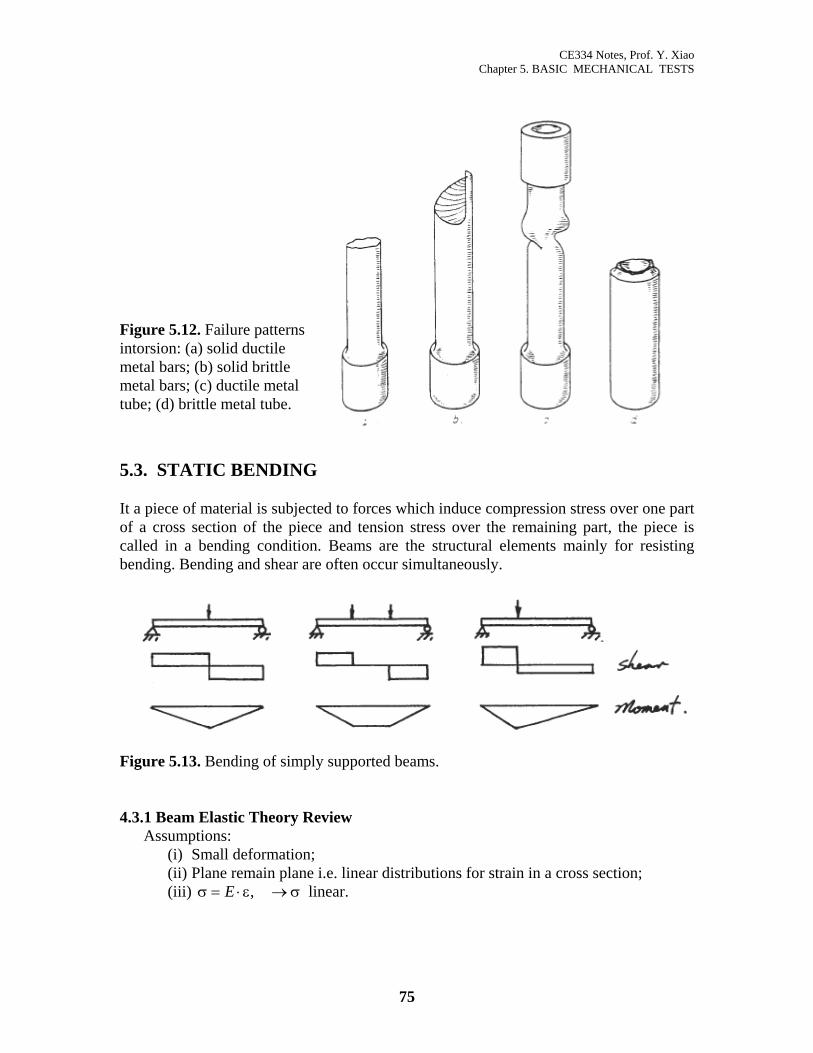
capable to apply and measure the toques. Figure 5.12 shows typical types of failure patterns. Spring: Helical springs subjected to tension or compression constitute one type of shear conditions since stresses developed in the spring wire sections are essentially dominated by torsional shear stresses.
74
CE334 Notes, Prof. Y. Xiao Chapter 5. BASIC MECHANICAL TESTS
Figure 5.12. Failure patterns intorsion: (a) solid ductile metal bars; (b) solid brittle metal bars; (c) ductile metal tube; (d) brittle metal tube.
5.3. STATIC BENDING It a piece of material is subjected to forces which induce compression stress over one part of a cross section of the piece and tension stress over the remaining part, the piece is called in a bending condition. Beams are the structural elements mainly for resisting bending. Bending and shear are often occur simultaneously.
Figure 5.13. Bending of simply supported beams. 4.3.1 Beam Elastic Theory Review
Assumptions: (i) Small deformation; (ii) Plane remain plane i.e. linear distributions for strain in a cross section; (iii) σ ε σ= ⋅ →E , linear.
75
CE334 Notes, Prof. Y. Xiao Chapter 5. BASIC MECHANICAL TESTS
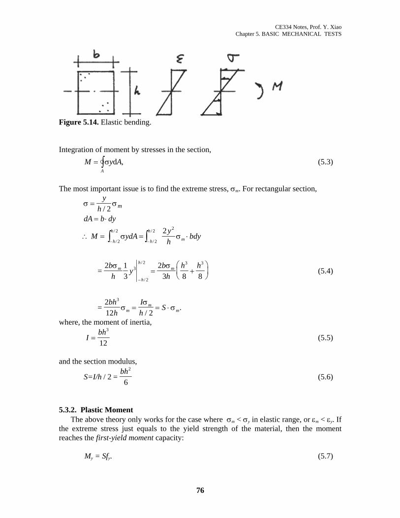
Figure 5.14. Elastic bending. Integration of moment by stresses in the section, M y
A
= ∫ σ dA, (5.3)
The most important issue is to find the extreme stress, σm. For rectangular section,
σ σ=
= ⋅
yh
dA b dy
m/ 2
∴ = = ⋅
= +⎛⎝⎜
⎞⎠⎟
= = ⋅
− −
−
∫ ∫M ydAyh
bdy
bh
yb
hh h
bhh
Ih
S
h
h
h
h
m
mh
h
m
mm
m
σ σ
σ σ
σσ
σ
/
/
/
/
/
/
/.
2
2
2
2 2
32
2
3 3
2
13
23 8 8
2
=2
=212
3
(5.4)
where, the moment of inertia,
Ibh
=3
12 (5.5)
and the section modulus,
S=I/hbh
/ 2 =6
2
(5.6)
5.3.2. Plastic Moment
The above theory only works for the case where σm < σy in elastic range, or εm < εy. If the extreme stress just equals to the yield strength of the material, then the moment reaches the first-yield moment capacity:
My = Sfy. (5.7)
76
CE334 Notes, Prof. Y. Xiao Chapter 5. BASIC MECHANICAL TESTS
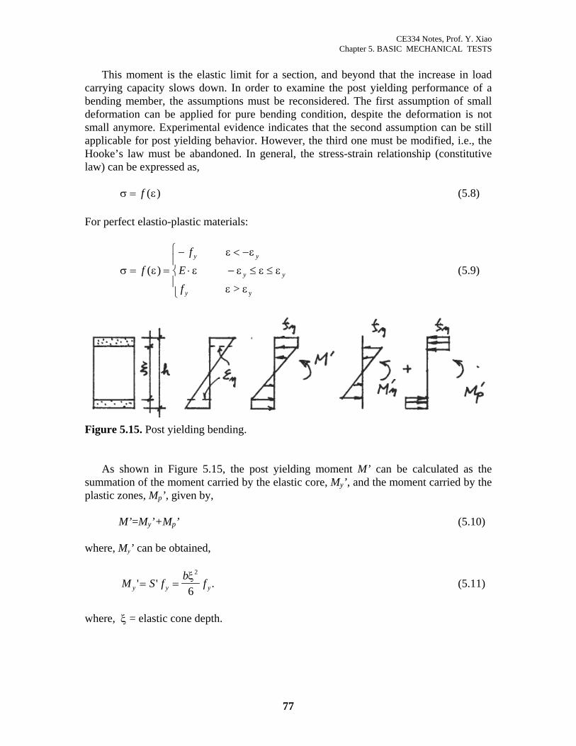
ε)
ε y
This moment is the elastic limit for a section, and beyond that the increase in load carrying capacity slows down. In order to examine the post yielding performance of a bending member, the assumptions must be reconsidered. The first assumption of small deformation can be applied for pure bending condition, despite the deformation is not small anymore. Experimental evidence indicates that the second assumption can be still applicable for post yielding behavior. However, the third one must be modified, i.e., the Hooke’s law must be abandoned. In general, the stress-strain relationship (constitutive law) can be expressed as, (5.8) σ = f ( For perfect elastio-plastic materials:
(5.9) σ ε
ε ε
ε ε ε
ε ε
= =
− < −
⋅ − ≤ ≤
⎧
⎨⎪
⎩⎪
ff
Ef
y y
y
y
( )
> y
Figure 5.15. Post yielding bending. As shown in Figure 5.15, the post yielding moment M’ can be calculated as the
summation of the moment carried by the elastic core, My’, and the moment carried by the plastic zones, Mp’, given by,
M’=My’+Mp’ (5.10) where, My’ can be obtained,
M S fb
fy y' '= =ξ2
6 y . (5.11)
where, ξ = elastic cone depth.
77
CE334 Notes, Prof. Y. Xiao Chapter 5. BASIC MECHANICAL TESTS
( )
( ) ( )
M f bh h
f b hh
f b h h
p y
y
y
'= −⎛⎝⎜
⎞⎠⎟
× + −⎛⎝⎜
⎞⎠⎟
⎡
⎣⎢
⎤
⎦⎥
− ⋅ + −⎡⎣⎢
⎤⎦⎥
− +
22 2 2 2 2
12
12 2 2
14
ξ ξ ξ
ξ ξξ
ξ ξ
=
=
(a)
thus,
( )M b hp '= −14
2 2ξ f y (5.12)
Substituting equations (5.11) and (5.12) to equation (5.10),
( )
M M M bfh b h
fy p y' ' '= + = + −⎛⎝⎜
⎞⎠⎟
−ξ ξ ξ2 2 2 2 2
6 4 43
12= y (5.13)
or,
M S fy y'= (5.14)
( )S
b hy =
−312
2 2ξ (5.15)
Compare with S,
( ) ( ) ( )
Sb h h bh b h
Sb h
y =+ −
= +−
= +−2
12 6 12 12
2 2 2 2 2 2 2 2ξ ξ ξ
Apparently, Sy>S, and M’>My, i.e. load can be increased. Rewriting Sy using strain ductility factor,
µξ
εεε = = ≥
h s
y1 (5.16)
(Sbh bh
hy = + −2 2
2 2
6 121 ξ / ) (a)
S S Sy = + −⎛⎝⎜
⎞⎠⎟
12
11
2µ. (5.17)
When, µ = 1, Sy = S, M = My.
78
CE334 Notes, Prof. Y. Xiao Chapter 5. BASIC MECHANICAL TESTS
µ = ∞ = = +, S Z Sy12
S
Plastic modulus,
Zbh
=2
4 (5.18)
Plastic moment for rectangular section,
M Z fbh
fp y= ⋅ =2
4 y (5.19)
5.3.3. Moment and Curvature Relationship As shown in Figure 5.15, the post-yield curvature can be defined as,
ϕε ε
ξεξ
= = =m y
h / /2 22 y (5.20)
The curvature at the first yield of the section,
ϕε ε
yy
h= = y
h/ 22
(5.21)
Curvature ductility factor can then be defined as,
µϕϕ
εε
εε
µϕ = = = =y
m
y
m
y
hh
22
// ε (5.22)
i.e., the curvature ductility factor is equal to the strain ductility factor. On the other hand, the ratio between the post yield moment and the first yield moment can be defined as the over-strength ratio,
αµ
= = = + −⎛⎝⎜
⎞⎠⎟
MM
SSy
y'.1 0 5 1
12 . (5.23)
From equation (5.23), the ductility factor can also be expressed as the over-strength factor,
79
CE334 Notes, Prof. Y. Xiao Chapter 5. BASIC MECHANICAL TESTS
µ =
− −⎛
⎝⎜⎜
⎞
⎠⎟⎟
1
1 2 1M
M y
(4.24)
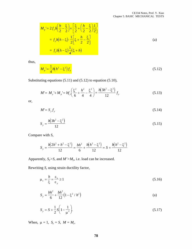
Numerical values, µ = 1 α = 1
µ = 1.2 α = 1.153 µ = 1.4 α = 1.245 µ = 1.6 α = 1.305 µ = 1.8 α = 1.346 µ = 2 α = 1.375 µ = 4 α = 1.469 µ = 6 α = 1.486 µ = 10 α = 1.495 µ = ∞ α = 1.5
Figure 5.16. Moment curvature relationship for rectangular section. The post yield moment is dependent on the shape of the section. Figure 5.17 shows the moment-curvature relationships for several typical sections.
80
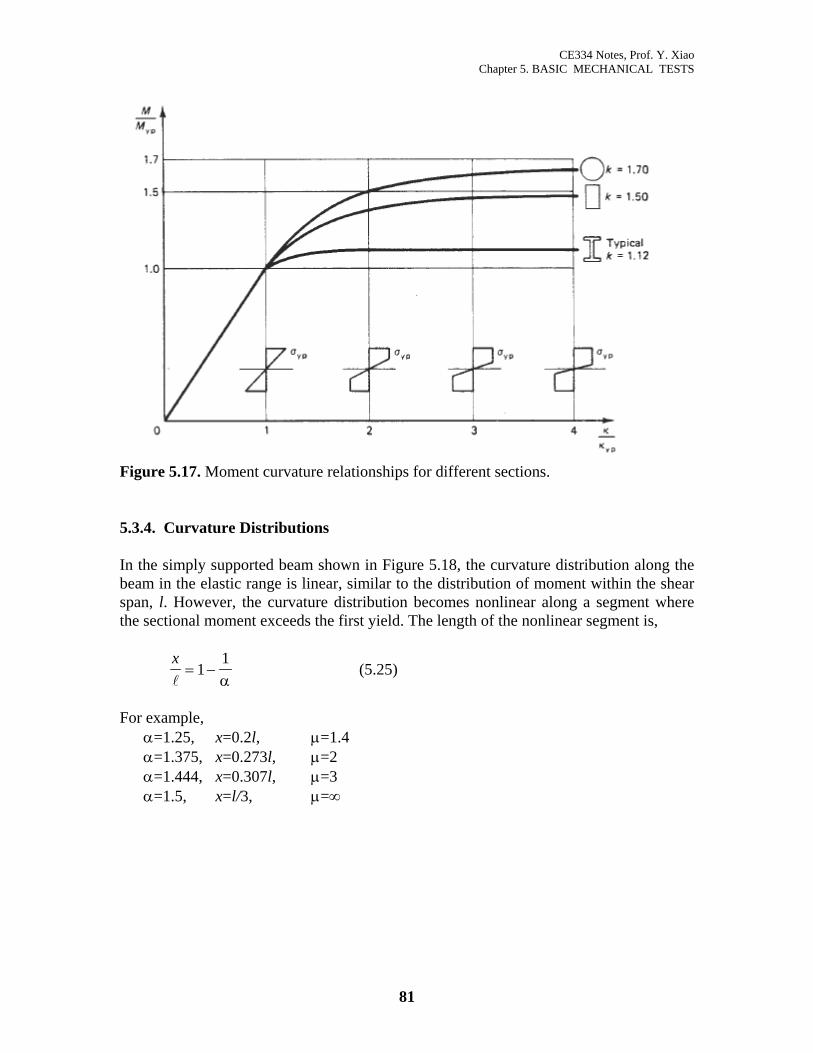
CE334 Notes, Prof. Y. Xiao Chapter 5. BASIC MECHANICAL TESTS
Figure 5.17. Moment curvature relationships for different sections. 5.3.4. Curvature Distributions In the simply supported beam shown in Figure 5.18, the curvature distribution along the beam in the elastic range is linear, similar to the distribution of moment within the shear span, l. However, the curvature distribution becomes nonlinear along a segment where the sectional moment exceeds the first yield. The length of the nonlinear segment is,
x
= −11α
(5.25)
For example,
α=1.25, x=0.2l, µ=1.4 α=1.375, x=0.273l, µ=2 α=1.444, x=0.307l, µ=3 α=1.5, x=l/3, µ=∞
81
CE334 Notes, Prof. Y. Xiao Chapter 5. BASIC MECHANICAL TESTS
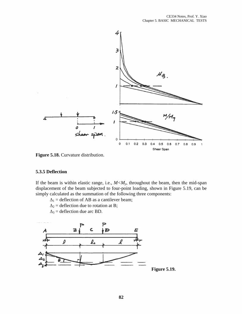
Figure 5.18. Curvature distribution. 5.3.5 Deflection If the beam is within elastic range, i.e., M<My, throughout the beam, then the mid-span displacement of the beam subjected to four-point loading, shown in Figure 5.19, can be simply calculated as the summation of the following three components: ∆1 = deflection of AB as a cantilever beam; ∆2 = deflection due to rotation at B; ∆3 = deflection due arc BD.
Figure 5.19.
82
CE334 Notes, Prof. Y. Xiao Chapter 5. BASIC MECHANICAL TESTS
∆
∆
∆
12
2
13
12
22
21
4 83
=
= ⋅ =
= =⎛⎝⎜
⎞⎠⎟ =
⎧
⎨
⎪⎪⎪
⎩
⎪⎪⎪
ϕ
θ ϕ
ϕθ
ϕϕ ϕ
B
c B
B B
c B c B
l
l l l
l l
elastic
sin sin
2
2 2
(5.26)
After the beam developed yielding, the deflection can be found by solving the following fundamental governing equation,
d xdx
x∆2
2( )
( )= ϕ (5.27)
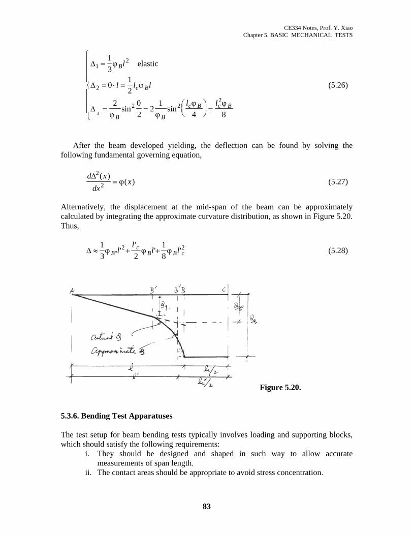
Alternatively, the displacement at the mid-span of the beam can be approximately calculated by integrating the approximate curvature distribution, as shown in Figure 5.20. Thus,
∆ ≈ + +13 2
18
2ϕ ϕ ϕBc
B Bll
l" ''
' 2cl' (5.28)
Figure 5.20. 5.3.6. Bending Test Apparatuses The test setup for beam bending tests typically involves loading and supporting blocks, which should satisfy the following requirements:
i. They should be designed and shaped in such way to allow accurate measurements of span length.
ii. The contact areas should be appropriate to avoid stress concentration.
83
CE334 Notes, Prof. Y. Xiao Chapter 5. BASIC MECHANICAL TESTS
iii. The supports should allow longitudinal adjustment to avoid the secondary
restraint to the length change. iv. The supports and loading blocks should accommodate slight rotational
adjustment to avoid the build up of torsional stresses. v. The arrangement of parts should be stable under load.
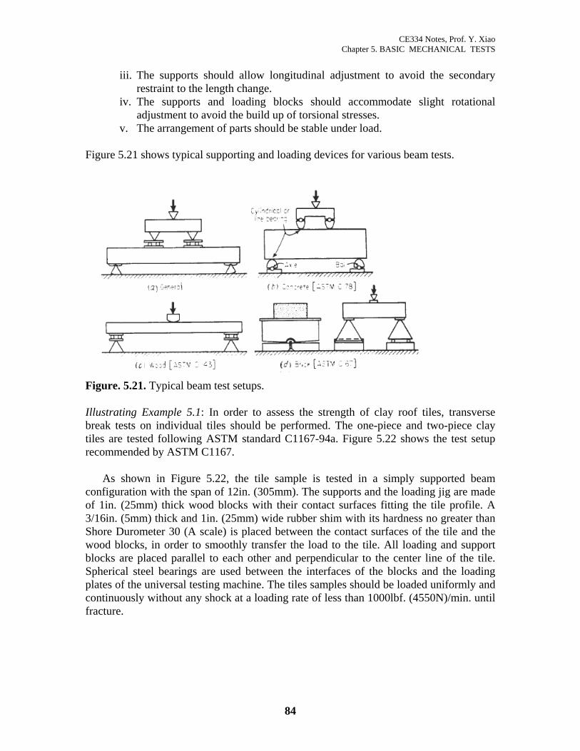
Figure 5.21 shows typical supporting and loading devices for various beam tests.
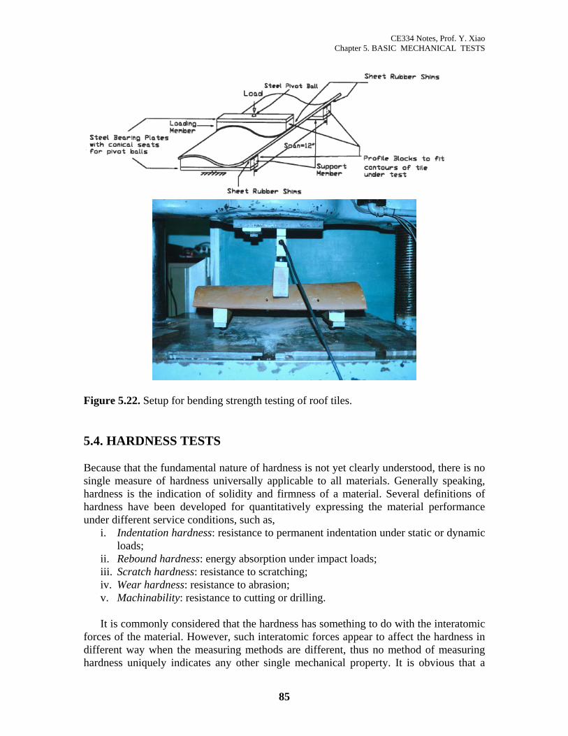
Figure. 5.21. Typical beam test setups. Illustrating Example 5.1: In order to assess the strength of clay roof tiles, transverse break tests on individual tiles should be performed. The one-piece and two-piece clay tiles are tested following ASTM standard C1167-94a. Figure 5.22 shows the test setup recommended by ASTM C1167.
As shown in Figure 5.22, the tile sample is tested in a simply supported beam configuration with the span of 12in. (305mm). The supports and the loading jig are made of 1in. (25mm) thick wood blocks with their contact surfaces fitting the tile profile. A 3/16in. (5mm) thick and 1in. (25mm) wide rubber shim with its hardness no greater than Shore Durometer 30 (A scale) is placed between the contact surfaces of the tile and the wood blocks, in order to smoothly transfer the load to the tile. All loading and support blocks are placed parallel to each other and perpendicular to the center line of the tile. Spherical steel bearings are used between the interfaces of the blocks and the loading plates of the universal testing machine. The tiles samples should be loaded uniformly and continuously without any shock at a loading rate of less than 1000lbf. (4550N)/min. until fracture.
84
CE334 Notes, Prof. Y. Xiao Chapter 5. BASIC MECHANICAL TESTS
Figure 5.22. Setup for bending strength testing of roof tiles. 5.4. HARDNESS TESTS Because that the fundamental nature of hardness is not yet clearly understood, there is no single measure of hardness universally applicable to all materials. Generally speaking, hardness is the indication of solidity and firmness of a material. Several definitions of hardness have been developed for quantitatively expressing the material performance under different service conditions, such as,
i. Indentation hardness: resistance to permanent indentation under static or dynamic loads;
ii. Rebound hardness: energy absorption under impact loads; iii. Scratch hardness: resistance to scratching; iv. Wear hardness: resistance to abrasion; v. Machinability: resistance to cutting or drilling.
It is commonly considered that the hardness has something to do with the interatomic
forces of the material. However, such interatomic forces appear to affect the hardness in different way when the measuring methods are different, thus no method of measuring hardness uniquely indicates any other single mechanical property. It is obvious that a
85
CE334 Notes, Prof. Y. Xiao Chapter 5. BASIC MECHANICAL TESTS
given type of test is of practical use only for comparing the relative hardnesses of similar materials on a common basis. For example, the results of ball-indentation tests on steel serve nicely to evaluate the effectiveness of a series of heat-treatments on a given steel or even to classify steels of various compositions, but have no meaning when compared with results of such tests performed on rubber. 5.4.1 Standard Tests
Static indentation hardness tests are based on the principle of applying a static load on an indenter, which in turn permanently deforms the specimen.
The Brinell tests consists of pressing a hardened steel ball into a specimen. According
to ASTM specifications (ASTM E 10), the steel ball is 10mm in diameter and the load used is 3000kgf for hard metals, 1500kgf for metals of intermediate hardness and 500kgf for soft materials.
The Rockwell test is similar to the Brinell test in principle, however, the indenters and
the loads used are smaller (the masses being 60, 100, or 150 kg) and the resulting indentation is smaller and shallower. The test is widely used in industrial work and the procedure has been standardized by ASTM E 18. The details of the Rockwell test will be discussed in the next section.
The Rockwell superficial-hardness test uses a special-purpose machine intended
exclusively for hardness tests where only very shallow indentation is possible and where it is desirable to know the hardness of the specimen close to the surface, such as for nitrided steel, razor blades, lightly carburized work, brass, bronze and steel sheet.
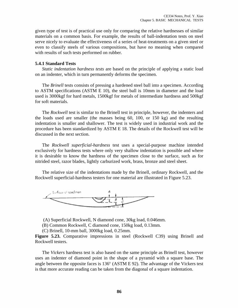
The relative size of the indentations made by the Brinell, ordinary Rockwell, and the
Rockwell superficial-hardness testers for one material are illustrated in Figure 5.23.
(A) Superficial Rockwell, N diamond cone, 30kg load, 0.046mm. (B) Common Rockwell, C diamond cone, 150kg load, 0.13mm. (C) Brinell, 10-mm ball, 3000kg load, 0.25mm.
Figure 5.23. Comparative impressions in steel (Rockwell C39) using Brinell and Rockwell testers.
The Vickers hardness test is also based on the same principle as Brinell test, however
uses an indenter of diamond point in the shape of a pyramid with a square base. The angle between the opposite faces is 136° (ASTM E 92). The advantage of the Vickers test is that more accurate reading can be taken from the diagonal of a square indentation.
86
CE334 Notes, Prof. Y. Xiao Chapter 5. BASIC MECHANICAL TESTS
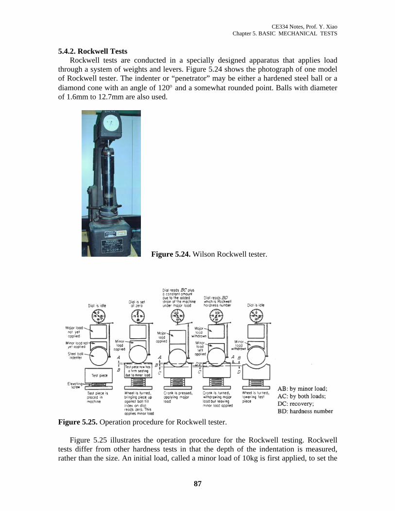
5.4.2. Rockwell Tests
Rockwell tests are conducted in a specially designed apparatus that applies load through a system of weights and levers. Figure 5.24 shows the photograph of one model of Rockwell tester. The indenter or “penetrator” may be either a hardened steel ball or a diamond cone with an angle of 120° and a somewhat rounded point. Balls with diameter of 1.6mm to 12.7mm are also used.
Figure 5.24. Wilson Rockwell tester.
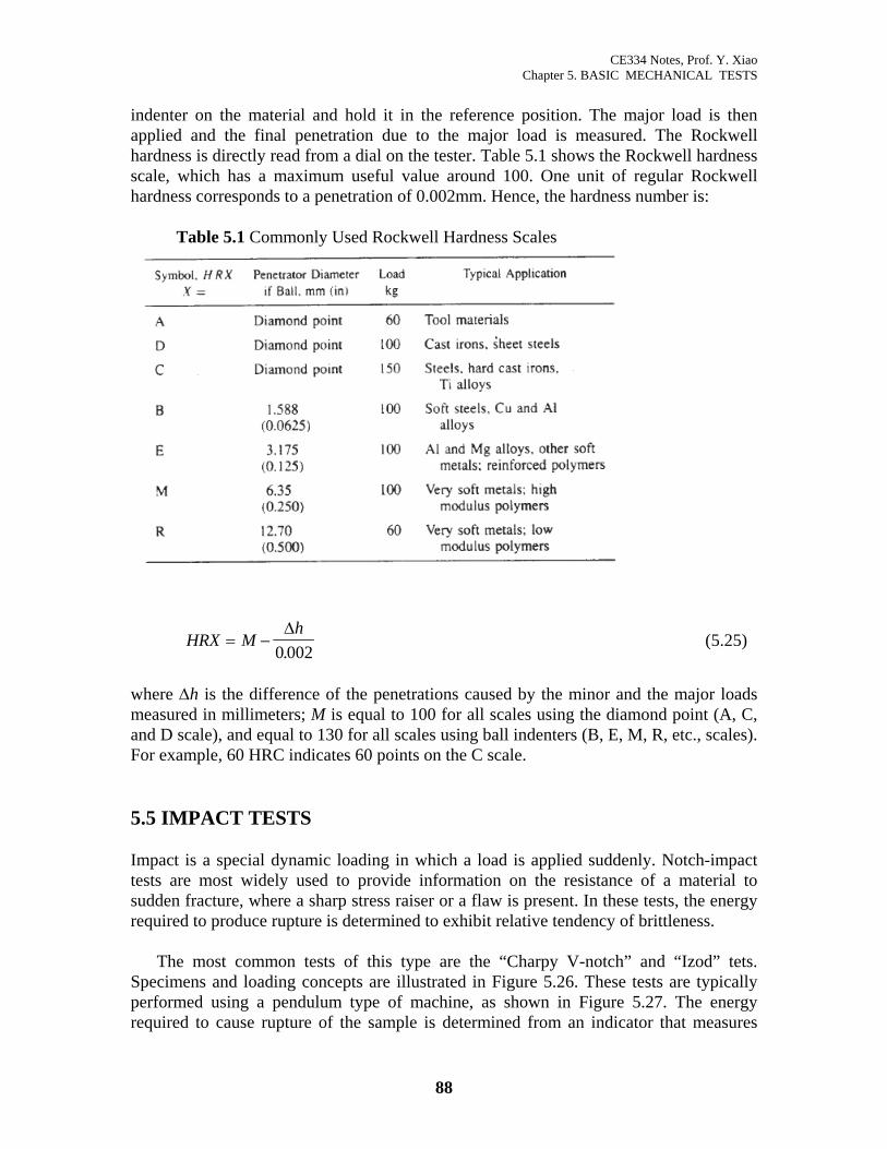
Figure 5.25. Operation procedure for Rockwell tester.
Figure 5.25 illustrates the operation procedure for the Rockwell testing. Rockwell tests differ from other hardness tests in that the depth of the indentation is measured, rather than the size. An initial load, called a minor load of 10kg is first applied, to set the
87
CE334 Notes, Prof. Y. Xiao Chapter 5. BASIC MECHANICAL TESTS
indenter on the material and hold it in the reference position. The major load is then applied and the final penetration due to the major load is measured. The Rockwell hardness is directly read from a dial on the tester. Table 5.1 shows the Rockwell hardness scale, which has a maximum useful value around 100. One unit of regular Rockwell hardness corresponds to a penetration of 0.002mm. Hence, the hardness number is:
Table 5.1 Commonly Used Rockwell Hardness Scales
HRX Mh
= −∆
0 002. (5.25)
where ∆h is the difference of the penetrations caused by the minor and the major loads measured in millimeters; M is equal to 100 for all scales using the diamond point (A, C, and D scale), and equal to 130 for all scales using ball indenters (B, E, M, R, etc., scales). For example, 60 HRC indicates 60 points on the C scale. 5.5 IMPACT TESTS Impact is a special dynamic loading in which a load is applied suddenly. Notch-impact tests are most widely used to provide information on the resistance of a material to sudden fracture, where a sharp stress raiser or a flaw is present. In these tests, the energy required to produce rupture is determined to exhibit relative tendency of brittleness.
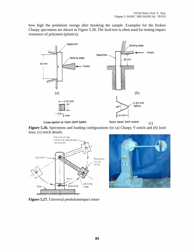
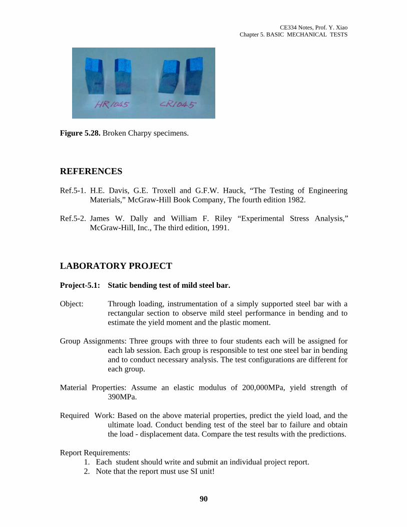
The most common tests of this type are the “Charpy V-notch” and “Izod” tets. Specimens and loading concepts are illustrated in Figure 5.26. These tests are typically performed using a pendulum type of machine, as shown in Figure 5.27. The energy required to cause rupture of the sample is determined from an indicator that measures
88
CE334 Notes, Prof. Y. Xiao Chapter 5. BASIC MECHANICAL TESTS
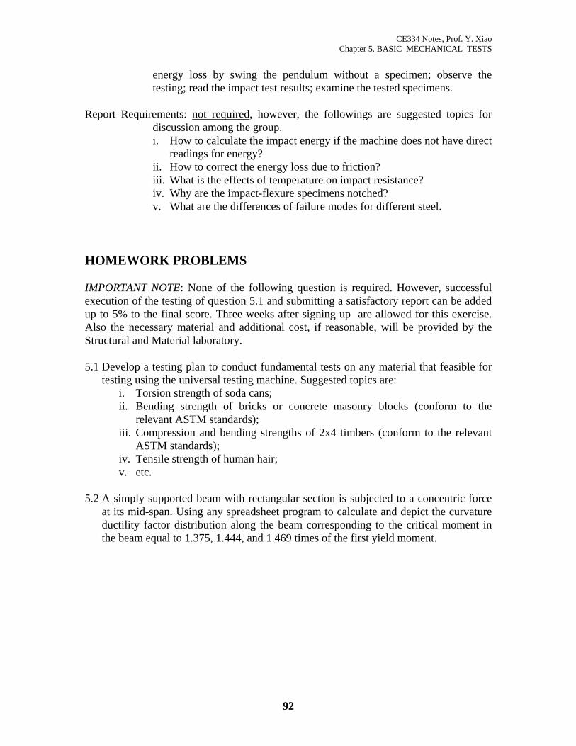
how high the pendulum swings after breaking the sample. Examples for the broken Charpy specimens are shown in Figure 5.28. The Izod test is often used for testing impact resistance of polymers (plastics).
(a) (b)
(c) Figure 5.26. Specimens and loading configurations for (a) Charpy V-notch and (b) Izod tests; (c) notch details.
Figure 5.27. Universal pendulumimpact tester
89
CE334 Notes, Prof. Y. Xiao Chapter 5. BASIC MECHANICAL TESTS
Figure 5.28. Broken Charpy specimens. REFERENCES Ref.5-1. H.E. Davis, G.E. Troxell and G.F.W. Hauck, “The Testing of Engineering
Materials,” McGraw-Hill Book Company, The fourth edition 1982. Ref.5-2. James W. Dally and William F. Riley “Experimental Stress Analysis,”
McGraw-Hill, Inc., The third edition, 1991. LABORATORY PROJECT Project-5.1: Static bending test of mild steel bar. Object: Through loading, instrumentation of a simply supported steel bar with a
rectangular section to observe mild steel performance in bending and to estimate the yield moment and the plastic moment.
Group Assignments: Three groups with three to four students each will be assigned for
each lab session. Each group is responsible to test one steel bar in bending and to conduct necessary analysis. The test configurations are different for each group.
Material Properties: Assume an elastic modulus of 200,000MPa, yield strength of
390MPa. Required Work: Based on the above material properties, predict the yield load, and the
ultimate load. Conduct bending test of the steel bar to failure and obtain the load - displacement data. Compare the test results with the predictions.
Report Requirements:
1. Each student should write and submit an individual project report. 2. Note that the report must use SI unit!
90

CE334 Notes, Prof. Y. Xiao Chapter 5. BASIC MECHANICAL TESTS
3. The report should cover the followings, but should not exceed 3 A4 pages.
This page limit should be strictly followed. i. A brief description of the project. ii. Description of the test including sample dimensions and test setup and
procedure. iii. Pre-test prediction to the first yield load and the ultimate load. iii. Test results of load - deflection curve. Compare the predicted loads in the
same figure. iv. Brief description of the comparison for the yield and ultimate loads. . v. A brief conclusion.
Project-5.2: Hardness tests of steel. Object: To study the Rockwell hardness testers and to determine the hardness
numbers of assigned specimens of steel and compare the effects of carbon contents and heat treatment.
Group Assignments: Four groups with three students each will be assigned for each lab
session. Required Work: Each group is responsible to test three steel samples assigned. Each
student within a group is responsible to conduct three tests on one specimen and record the hardness numbers.
Report Requirements:
1. Each group should write and submit an individual project report. 2. The report should cover the followings, but should not exceed 3 A4 pages.. i. A brief description of the project. ii. Description of the test including samples and test setup and procedure. iii. Tabulate the tested and average hardness numbers for each specimen. iv. Brief description of the trend of the hardness related to the carbon content and
heat treatment. v. A brief conclusion.
Project-5.3: Impact tests. Object: To study the pendulum type impact-testing machine and to determine the
relative impact resistance of a steel in the form of notched-bar Charpy specimens.
Group Assignments: The full lab session as one group. Required Work: Observe the specimens and the machine prior the testing; study the
operating procedures including safety issues; examine and obtain the
91
CE334 Notes, Prof. Y. Xiao Chapter 5. BASIC MECHANICAL TESTS
energy loss by swing the pendulum without a specimen; observe the testing; read the impact test results; examine the tested specimens.
Report Requirements: not required, however, the followings are suggested topics for
discussion among the group. i. How to calculate the impact energy if the machine does not have direct
readings for energy? ii. How to correct the energy loss due to friction? iii. What is the effects of temperature on impact resistance? iv. Why are the impact-flexure specimens notched? v. What are the differences of failure modes for different steel.
HOMEWORK PROBLEMS IMPORTANT NOTE: None of the following question is required. However, successful execution of the testing of question 5.1 and submitting a satisfactory report can be added up to 5% to the final score. Three weeks after signing up are allowed for this exercise. Also the necessary material and additional cost, if reasonable, will be provided by the Structural and Material laboratory. 5.1 Develop a testing plan to conduct fundamental tests on any material that feasible for
testing using the universal testing machine. Suggested topics are: i. Torsion strength of soda cans; ii. Bending strength of bricks or concrete masonry blocks (conform to the
relevant ASTM standards); iii. Compression and bending strengths of 2x4 timbers (conform to the relevant
ASTM standards); iv. Tensile strength of human hair; v. etc.
5.2 A simply supported beam with rectangular section is subjected to a concentric force
at its mid-span. Using any spreadsheet program to calculate and depict the curvature ductility factor distribution along the beam corresponding to the critical moment in the beam equal to 1.375, 1.444, and 1.469 times of the first yield moment.
92