chapter 4 acceptance testing - eac.gov
TRANSCRIPT

***
C h A P T E r 4
ACCEPTANCE TESTING
Introduction
Acceptance testing of voting systems is perhaps the
most important function that local election jurisdic-
tions undertake in order to ensure the security and
accuracy of their elections. Acceptance tests must be
conducted under the strict control of the chief elec-
tion offcial of the jurisdiction. Under no circum-
stance should acceptance tests be conducted by
a manufacturer.
An acceptance test is defned as a test that is per-
formed on an individual unit of a voting system in
order to verify that the unit is physically, electroni-
cally, mechanically, and functionally correct. Cor-
rect, in this sense, means that the unit is identical in
every respect, including software/frmware to the unit
that was originally purchased.
Acceptance testing provides assurance that the
voting system is functioning correctly, that the
voting system complies with the conditions of the
product acquisition document, and that the voting
system is correctly confgured for use in an election.
If initial acceptance testing is successful, the test
documentation becomes the frst item in the chain
of custody for the elements that comprise the voting
system. Later, if a component of the voting system
leaves the election offcials direct control for any
reason (i.e. repair, upgrade, etc.) a repeat of the initial
acceptance test serves to re-establish your chain of
custody for the component.
IMPOrTANT rEMINDEr
A certifed voting system consists of a specifc set of
hardware/software/frmware, the specifc version of the
operating system, and the specifc versions of any support
software In order to conduct acceptance tests you must
know the version levels of each of these components.
It is extremely important that election offcials
maintain a complete record of every acceptance test
conducted on your voting system. These records should
contain the device identifcation including software/
frmware version, the date of the test, the name of
the tester(s), and the outcome of the test. If the device
passes the test no further information is necessary. If
the device fails the acceptance test, the test documenta-
tion should contain a detailed description of the reason
for the failure. If the failed device is returned to the
manufacturer for repair, it is recommended that a copy
of the test documentation be returned with the device.
Keeping all documentation on your election system
in a single, easily accessible place can aid your manage-
ment decisions. Ideally, you should build a database
that can track the components of your system through-
out their life. In it you would store the results from
every acceptance test conducted, all election-related
performance data, all chain-of-custody data, etc. This
database becomes a single place to track each compo-
nent of the voting system by serial number.
Request for Proposal and Contract Considerations
Planning for acceptance testing begins with the
development of the Request for Proposal (RFP). The
RFP should require that the vendor’s bid proposals
contain a recommended acceptance test script for
each device contained in the proposal and an accep-
tance script for the overall voting system.
The RFP should specify that the proposed scripts
must apply equally to all devices of a given type.
For example, if the script is for a DRE voting station
it must apply uniformly to all DRE voting stations.
Do not accept a script that calls for a rigorous test of
some subset of the DREs and only a cursory inspec-
tion of the rest.
ELECTION MANAGEMENT GUIDELINES 29
The manufacturer’s proposed acceptance test
scripts will generally not be entirely satisfactory, but
they will provide election offcials with a solid basis
for developing their own scripts.
Contracts for voting systems usually include a
progressive payment schedule that calls for the total
value of the contract to be paid in a series of payments
based on measurable deliverables, such as hardware
delivery, software installation and testing, etc. One of
these payments should be based on completion of suc-
cessful acceptance testing of all devices that make up
the voting system and a successful acceptance test of
the overall system.
RECOMMENDATION The fnal payment should be based
on the successful completion of the frst election held using
the voting system.
Acceptance Tests
There are three distinct parts to an acceptance test:
a test for physical integrity, a diagnostic test of the
various hardware features, and a test for functional
characteristics. This last test includes a test of the various
software/hardware modules that control the unit.
Acceptance tests must be conducted on every
unit of your voting system every time a unit leaves
your control and is returned. For example, if you
loan a voting station to a civic club for a demonstration
or send a unit of the voting system out for repair. Note
that this does not include functions under the con-
trol of staff of the elections offce. If you have a large
number of devices this may be a tedious and time
consuming task. Fortunately, as with most tedious and
time consuming tasks, acceptance testing usually pro-
ceeds more quickly as the testers gain experience
with the voting system. In some instances, an expe-
rienced tester can perform an acceptance test on
a touch screen voting station or a ballot scanner in
less than ffteen minutes.
In the course of an acceptance test, the tester may
experience problems that can be easily corrected by the
tester such as an incorrect time or date or a poorly
calibrated touch screen. This is not a cause for termi-
nating the test. In these cases, the tester should cor-
rect the problem and continue the test. However, the
problem should be noted in the unit documentation.
Physical Analysis: This portion of the acceptance
test is performed to assure that the voting unit is not
physically damaged and that all physical components
are working properly. The specifc tests will vary based
on the particular voting system; however, some typical
items will include:
Examine the outer shell or case for any sign of
damage such as dents or cracks.
Check that the top and bottom of the shell mate
easily, that all doors open and shut easily, etc.
Inspect all latches and hinges. Latches should open
and shut without binding.
Hinges should operate smoothly and be inspected
to insure that hinge pins are not easily removed.
All locks should open and close without binding.
Inspect all electrical wires and connectors for
damage or signs of wear.
Diagnostic Analysis: This portion of the acceptance
test is performed to assure that all of the mechanical
and electronic components of the voting unit are
operating correctly. Again, the specifc tests will vary
based on the particular voting system; however, some
typical items will include:
Test all input/output devices. This will include any
voter card readers, printers, PC card slots, etc.
Test the connections that support any accessibility
devices. If accessibility devices use a serial port, use
a loop-back connector to test this port.
On ballot scanners verify that the ballot feed path
is properly set and that ballots will feed without
binding.
On touch screen devices verify that the screen is
calibrated correctly.
If there are controls that the voter can use to
change brightness or intensity, verify that these
controls are working properly.
If the device is a commercial computer, verify that
the foppy disk drives, CD/DVD drives, PC Slots,
etc. are working properly.
If the devices record date and time, verify that the
date and time are correct.
Functional Analysis: This test is performed to assure
that the correct Federal and State certifed version(s)
of the software/frmware are installed in the voting
unit and that the system will perform correctly
3 0 U.S. ELECTION ASSISTANCE COMMISSION
during an election. This test consists of loading a
mock election onto the unit, casting a known pat-
tern of votes, closing the election, printing the reports,
and then comparing the test results with the known
vote pattern.
The following sections provide a generic outline for
developing an acceptance test for the most common
devices found in an electronic voting system. In each
of the tests described below, you will need to setup a
mock election. This mock election does not need to
be long; however, it should exercise the features of the
voting unit being tested. If your jurisdiction allows
straight party voting, straight party voting with
cross-over, multiple representative districts (i.e. vote
for n of m), etc. then these types of contests should be
included in your mock election.
Acceptance Tests for Optical Scan Ballot Scanners
This section describes an acceptance test for a stand-
alone ballot scanner. The scanner should be set up for
this test the way it will be set up for use in a precinct.
Materials Required: In addition to the following, you
must know the version of the operating system and/or
frmware that was certifed for your ballot scanner.
A memory card or other device that is used to
confgure the ballot scanner for an election. This
device must contain the election setup for the mock
election that you will be using to test the scanner.
The password, manager card, or other device that
is used to gain manager/administrator privilege on
the scanner.
A test deck of pre-marked optical scan ballots for
the mock election. This test deck typically contains
one ballot with a vote for the frst candidate in each
race, two ballots with votes for the second candi-
date, three ballots with votes for the third candidate,
etc. For ‘yes’ or ‘no’ questions, vote ‘yes’ on the frst
ballot and ‘no’ on the next two ballots. Do not vote
this question on subsequent ballots. Although
most ballot printers can supply you with this test
deck; it is recommended that these ballots be hand
prepared using the marking device noted by the
system manufacturer.
Physical Analysis: This analysis is conducted with
the scanner turned off.
1. Examine the case and/or cover for cracks or dents.
2. Inspect latches, hinges, carrying case, wheels, etc.
3. Examine the legs and/or stand. The legs and/or
stand must operate smoothly without binding.
4. Inspect the power cord and plug for any frayed
insulation or damaged connectors.
5. Verify that there is suffcient paper in the printer
to complete the test.
Diagnostic Analysis: This analysis is conducted with
the scanner turned on. Some of these tests may require
manager/administrator privilege.
1. Turn on the ballot scanner and, as it boots up,
verify that the correct Federal and State certifed
version of the operating system and software are
installed. This information may only display on
the screen briefy. If you miss it, turn the scanner
off and then re-boot.
2. Verify that the date and time set in the scanner are
correct and, if not, correct them.
3. Be aware of time changes due to daylight savings
time. If the daylight savings time will change
between the time of this test and the next election,
set the time on the scanner to compensate for
this change.
4. Print a test pattern to verify that the printer is
operating correctly. If your scanner does not have
the ability to print a test pattern, the printer can
be tested during the Functional Analysis.
5. Unplug the ballot scanner and verify that it will
operate on the battery. If the scanner will not
operate on the battery check to be sure the battery
is fully charged before failing the scanner.
6. Verify that the battery charger will charge the battery.
7. Test all ports and card slots. If the scanner uses a
serial port to communicate with the election man-
agement system, use a loop-back connector to test
this port.
Functional Analysis: This analysis is conducted with
the scanner loaded with the mock election and set for
election mode. Turn the scanner on, load the mock
election, and then set the scanner in election mode.
1. Be sure all vote totals are set to zero.
2. Print a zero tape.
3. Use the pre-marked test deck to accumulate a signif-
cant number of ballots (at least 25) on the scanner.
ELECTION MANAGEMENT GUIDELINES 31
4. Close the election on the ballot scanner.
5. Print the results tape.
6. Verify that the vote counts on the result tape match
the known results of the test deck.
7. Zero the vote counters and remove the mock elec-
tion from the scanner.
Documentation: If the scanner experiences a failure
during any of the above steps that cannot be corrected
by the tester, terminate the test. Prepare documenta-
tion that lists the serial number of the scanner, the
persons conducting the tests, the date, and a descrip-
tion of the failure. Make two copies of this docu-
mentation; one copy for your permanent record and
another copy that stays with the scanner to assist the
persons making any required repairs. Attach all print-
outs to the copy retained for your permanent record.
If the scanner passes all of the above tests, pre-
pare documentation for your permanent record that
lists the serial number of the scanner, the persons
conduction the tests, and the date. Attach all print-
outs to this documentation.
RECOMMENDATION It is important to be able to look at
a scanner and determine whether or not it has passed
acceptance testing. One way to accomplish this is to
attach a permanent, non-removable label to the back
or underside of the scanner. This label should contain the
serial number of the scanner, the date, and the name or
initials of the testers.
Acceptance Test for Touch-screen Voting Stations
This section describes a typical acceptance test for a
touch-screen voting station. The voting station should
be set up for this test the way it will be set up for use
in a precinct.
Material Required: In order to conduct an acceptance
test, you will need the following materials. You will
also need to know the version of the operating system
and the software/frmware on your voting stations.
A memory card or other device that contains
the mock election to be used for the test. This
will be used to load the mock election into the
voting station.
If the voting station uses a serial port to connect dis-
ability devices, you will need a loop-back connector.
A voter card or other device required to activate the
voting station for a voter.
The password, manager card, or other device
required for gaining manager/administrator privilege
on the voting station.
Physical Analysis: This analysis is conducted with the
voting station turned off.
1. Examine the case and/or cover for cracks or dents.
2. Inspect latches, hinges, carrying case, wheels, etc.
3. Examine the legs and/or stand. The legs and/or
stand must operate smoothly without binding.
4. Inspect the power cord and plug for any frayed
insulation or damaged connectors.
5. Verify that there is suffcient paper in the printer
to complete the test.
Diagnostic Analysis: This test is conducted with the
voting station turned on. Some parts of the test may
require manager/administrator privilege.
1. Turn the voting station on and as it boots up verify
that the correct Federal and State certifed version of
the operating system and frmware are installed.
This information may only appear briefy on the
screen. If you miss it, turn the voting station off
and then turn it back on.
2. Verify that the date and time are correct and correct
them if necessary.
3. Be aware of time changes due to daylight savings
time. If the daylight savings time will change
between the time of this test and the next election,
set the time on the scanner to compensate for this
change.
4. Check the calibration on the screen and re-calibrate
the screen if necessary.
5. Print a test pattern to verify that the printer is
operating correctly. If your voting station does not
have the ability to print a test pattern, the printer
can be tested during the Functional Analysis.
6. Examine the screen for condition and clarity.
7. Unplug the voting station and verify that it will
operate on the battery. If the battery is dead, charge
the battery and repeat this test.
8. Verify that the battery charger will charge the
32 U.S. ELECTION ASSISTANCE COMMISSION

battery and that any indicators that display charg-
ing condition and level of battery charge are func-
tioning properly.
9. Test all card slots and input/output ports. If the
voting station uses a serial port to connect the
accessibility devices, test this port using a loop-
back connector.
Functional Analysis: For this test the voting station is
turned on and the mock election is loaded.
1. Verify that the mock election loaded correctly and
that the ballot(s) contain all contests and candidates.
2. Set the voting station in election mode.
3. Print the Zero Totals tape.
4. Manually enter ballots that contain one vote for
each candidate and issue. Continue to manually
enter ballots until each candidate on the ballot
has received exactly one vote and each issue has
received one ‘yes’ and one ‘no’ vote.
5. Verify that each candidate has received exactly one
vote and each issue has received one ‘yes’ and one
‘no’ vote.
6. If the voting station has the ability to automatically
generate Logic and Accuracy ballots, use this feature
to enter a total number of ballots that exceeds the
number of ballots expected to be cast on a typical
election day (usually about 150).
7. Close the election on the voting station.
8. Print the results.
9. Verify that the printed results exactly match the
known number of votes cast for each candidate
and issue.
10. Zero the totals and close the voting station.
Documentation: If during any of the above steps the
voting station experiences a failure that cannot be
corrected by the tester, terminate the test. Prepare
documentation that lists the serial number of the
touch screen unit, the persons conducting the tests,
the date, and a description of the failure. Make two
copies of this documentation; one copy for your per-
manent record and another copy that stays with the
touch screen unit to assist the persons making any
required repairs. Attach all printouts to the copy
retained for your permanent record.
If the touch screen unit passes all of the above
tests, prepare documentation for your permanent
record that lists the serial number of the unit, the
persons conducting the tests, and the date. Attach all
printouts to this documentation.
RECOMMENDATION It is important to be able to look at a
voting station and determine whether or not it has success-
fully passed acceptance testing. One way to accomplish
this is to attach a permanent, non-removable label to the
back of the screen or underside of the voting station. This
label should contain the serial number of the voting station,
the date, and the name or initials of the testers.
End-to-end Voting System Acceptance Test
This test is sometimes referred to as a test of the
election management system. In reality, it not only
tests the election management system but also tests
the ability of the election management system to
interface correctly with the voting devices and to
correctly count the votes and print reports. This test
should be conducted on all newly acquired voting
systems, and also after any event that has the poten-
tial to alter the voting system. Such events include
replacing a disk drive or other component in the
election computer and any time the election com-
puter leaves your direct control and is returned.
IMPORTANT If you use a ‘blended system’, for example
optical scan and touch screen for ADA, all components
of the system must be included in this test.
Materials Required: You must know the correct
Federal and State certifed versions of the operating
systems and software/firmware for your election
management system and your vote gathering devices,
scanners and voting stations. In addition, you will
need the following:
1. An election management computer with your voting
system installed.
2. If Touch Screen units are used:
One Touch Screen voting unit,
One blank Touch Screen Memory Card or other
device used to load the election definition into
the voting unit,
One Touch Screen manager/supervisor card or
other device used to obtain manager/supervisor
access to the voting unit,
ELECTION MANAGEMENT GUIDELINES 3 3

One Touch Screen voter card or other device used
to initiate a voting session for a voter.
3. If Optical Scan Ballot Scanners are used:
One Ballot Scanner,
One blank memory card or other device used
to load the election definition into the ballot
scanner,
One set of pre-marked Optical Scan test ballots
with known results. This can be the same test
deck used to conduct acceptance tests on the
ballot scanner.
4. All communications cables and devices necessary
to connect the voting units and ballot scanners to
the election management computer.
5. One blank disk or other device used by your system
to record and store the election results.
6. One disk or other device containing your mock
acceptance test election setup.
Prerequisite: The election management system con-
sisting of items 1 through 4 above must be set up
and tested before beginning this acceptance test.
NOTE It is acceptable to allow your IT staff or the manu-
facturer to do this setup because in the course of conduct-
ing the end-to-end test you will verify that everything has
been set up correctly.
The Touch Screen voting unit and the ballot scan-
ner should have previously completed acceptance
testing. If not, run the Touch Screen voting station
acceptance test and the ballot scanner acceptance test
on these units prior to beginning this test.
Verify Correct Operating System and Election Man-
agement Software: Turn on the election management
computer. As the computer boots up, verify that the
correct Federal and State certifed version of the
operating system is installed. After the boot up is
complete, verify that the correct Federal and State
certifed version of the election management system is
installed. This can be accomplished by comparing the
hash values of the installed voting system software with
the hash values contained in the Web site of the
National Software Reference Library maintained by
the National Institute of Standards and Technology
(http://www nsrl nist gov/votedata html).
Verify the Election Management System Hardware:
Verify that all components of the election management
computer are turned on and functioning properly.
This includes such components as printers, communi-
cation devices, disk drives, etc.
Verify Voting System Functionality: This test will
verify that the overall voting system is functioning
properly. It will verify that the election management
system will format media to setup the TS voting sta-
tions and OS ballot scanners, that votes cast on these
devices can be uploaded to the election management
system, and that these votes will be counted correctly.
1. Load the acceptance test database (election setup)
on the election management computer.
2. Verify that the election management system will
support the Touch Screen voting unit (If your
voting system does not include Touch Screen units
go to Step 3).
Use the election management system to prepare
the memory card or other device that is used to
load the acceptance test mock election into the TS
voting unit.
Load the mock election into the voting unit.
Open the election on the unit.
Manually enter one vote for each candidate and
one ‘yes’ and one ‘no’ vote for each issue on the
ballot.
If the Touch Screen voting unit has the facility to
produce Logic and Accuracy ballots, use this fea-
ture to cast one set of Logic and Accuracy ballots.
Close the election on the Touch Screen
voting unit.
Print the vote totals on the voting station
printer.
Use your standard method for transferring votes
from the voting station to the election manage-
ment computer to upload the votes from the
voting unit to the election management system.
3. Verify that the election management system will
support the Optical Scan ballot scanner.
Use the election management system to prepare
the memory card or other device that is used to
load the acceptance test mock election into the
ballot scanner.
3 4 U.S. ELECTION ASSISTANCE COMMISSION

Load the mock election into the ballot scanner.
Open the election on the ballot scanner.
Use the pre-marked set of optical scan test ballots
to cast votes on the ballot scanner.
Close the election on the ballot scanner.
Print the vote totals on the ballot scanner.
Use your standard method for transferring votes
from the ballot scanner to the election manage-
ment computer to upload the votes from the ballot
scanner to the election management system.
4. Verify Printed Outputs.
Close the election on the election management
system.
Print the standard reports that contain the
vote totals.
Compare the results printed from the election
management system with the results printed from
the voting station and ballot scanner.
Documentation: If the voting system experiences a
failure during any of the above steps that cannot be
corrected by the tester, terminate the test. Prepare
documentation that lists the serial number of the
election computer and the serial number or other
identifying information for any other component
that failed, the persons conducting the tests, the date,
and a description of the failure. Make two copies of
this documentation; one copy for your permanent
record and another copy that stays with the touch
screen unit to assist the persons making any required
repairs. Attach all printouts to the copy retained for
your permanent record.
If the voting system passes all of the above tests,
prepare documentation for your permanent record
that lists the serial number of the voting system com-
puter, the serial number of the Touch Screen voting
unit, the serial number of the Optical Scan ballot
scanner, the persons conducting the tests, and the
date. Attach all printouts to this documentation.
RECOMMENDATION It is important to be able to look at a
voting system computer and determine whether or not it
has successfully passed acceptance testing. One way to
accomplish this is to attach a permanent, non-removable
label to the case of the voting system computer. This label
should contain the serial number of the computer, the date,
and the name or initials of the testers.
Conclusion
Acceptance testing on each machine delivered to a
voting jurisdiction by a manufacturer is a critical
step in the process of ensuring that electronic voting
units used by voters on Election Day will function as
intended. Although each manufacturer has internal
quality control procedures, and although quality
control should be guaranteed to some degree in the
contractual agreement between the manufacturer and
the voting jurisdiction, these procedures and guaran-
tees are worthless unless the jurisdiction can proac-
tively detect failures or non-functional systems at the
time the product is delivered. Rigorous acceptance
testing provides this detection mechanism.
RECOMMENDATION your agreement with the vendor
should include an understanding that the warranty on
a unit of the voting system will not begin until the initial
acceptance testing has been successfully completed.
ELECTION MANAGEMENT GUIDELINES 35
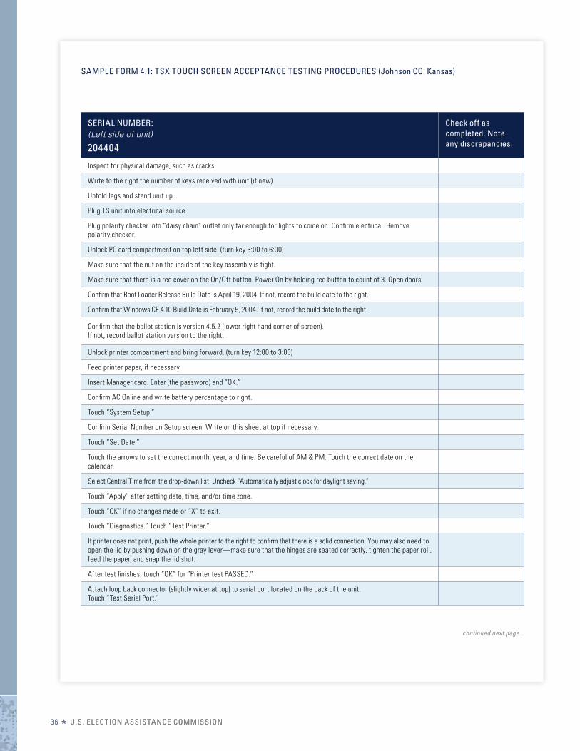
SAMPLE FOrM 4.1: TSX TOUCh SCrEEN ACCEPTANCE TESTING PrOCEDUrES (Johnson CO. Kansas)
SERIAL NUMBER: (Left side of unit)
204404
Check off as completed. Note any discrepancies.
Inspect for physical damage, such as cracks.
Write to the right the number of keys received with unit (if new).
Unfold legs and stand unit up.
Plug TS unit into electrical source.
Plug polarity checker into “daisy chain” outlet only far enough for lights to come on. Confrm electrical. Remove polarity checker.
Unlock PC card compartment on top left side. (turn key 3:00 to 6:00)
Make sure that the nut on the inside of the key assembly is tight.
Make sure that there is a red cover on the On/Off button. Power On by holding red button to count of 3. Open doors.
Confrm that Boot Loader Release Build Date is April 19, 2004. If not, record the build date to the right.
Confrm that Windows CE 4.10 Build Date is February 5, 2004. If not, record the build date to the right.
Confrm that the ballot station is version 4.5.2 (lower right hand corner of screen). If not, record ballot station version to the right.
Unlock printer compartment and bring forward. (turn key 12:00 to 3:00)
Feed printer paper, if necessary.
Insert Manager card. Enter (the password) and “OK.”
Confrm AC Online and write battery percentage to right.
Touch “System Setup.”
Confrm Serial Number on Setup screen. Write on this sheet at top if necessary.
Touch “Set Date.”
Touch the arrows to set the correct month, year, and time. Be careful of AM & PM. Touch the correct date on the calendar.
Select Central Time from the drop-down list. Uncheck “Automatically adjust clock for daylight saving.”
Touch “Apply” after setting date, time, and/or time zone.
Touch “OK” if no changes made or “X” to exit.
Touch “Diagnostics.” Touch “Test Printer.”
If printer does not print, push the whole printer to the right to confrm that there is a solid connection. You may also need to open the lid by pushing down on the gray lever—make sure that the hinges are seated correctly, tighten the paper roll, feed the paper, and snap the lid shut.
After test fnishes, touch “OK” for “Printer test PASSED.”
Attach loop back connector (slightly wider at top) to serial port located on the back of the unit. Touch “Test Serial Port.”
continued next page...
3366 UU..SS. E. ELLEECCTTIIOONN AASSSSIISSTTAANNCCEE CCOOMMMMIISSSSIIOONN
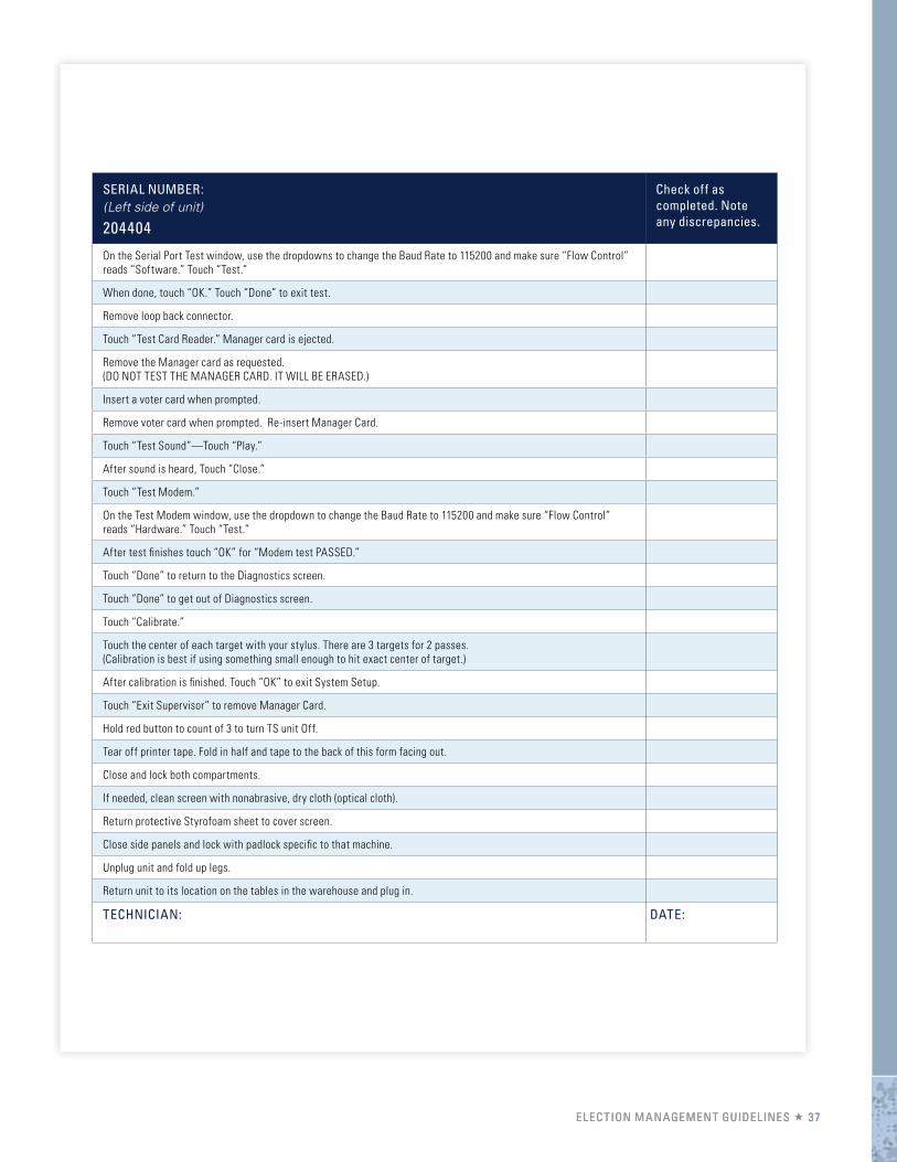
SERIAL NUMBER: (Left side of unit)
204404
Check off as completed. Note any discrepancies.
On the Serial Port Test window, use the dropdowns to change the Baud Rate to 115200 and make sure “Flow Control” reads “Software.” Touch “Test.”
When done, touch “OK.” Touch “Done” to exit test.
Remove loop back connector.
Touch “Test Card Reader.” Manager card is ejected.
Remove the Manager card as requested. (DO NOT TEST THE MANAGER CARD. IT WILL BE ERASED.)
Insert a voter card when prompted.
Remove voter card when prompted. Re-insert Manager Card.
Touch “Test Sound”—Touch “Play.”
After sound is heard, Touch “Close.”
Touch “Test Modem.”
On the Test Modem window, use the dropdown to change the Baud Rate to 115200 and make sure “Flow Control” reads “Hardware.” Touch “Test.”
After test fnishes touch “OK” for “Modem test PASSED.”
Touch “Done” to return to the Diagnostics screen.
Touch “Done” to get out of Diagnostics screen.
Touch “Calibrate.”
Touch the center of each target with your stylus. There are 3 targets for 2 passes. (Calibration is best if using something small enough to hit exact center of target.)
After calibration is fnished. Touch “OK” to exit System Setup.
Touch “Exit Supervisor” to remove Manager Card.
Hold red button to count of 3 to turn TS unit Off.
Tear off printer tape. Fold in half and tape to the back of this form facing out.
Close and lock both compartments.
If needed, clean screen with nonabrasive, dry cloth (optical cloth).
Return protective Styrofoam sheet to cover screen.
Close side panels and lock with padlock specifc to that machine.
Unplug unit and fold up legs.
Return unit to its location on the tables in the warehouse and plug in.
TEChNICIAN: DATE:
EELLEECCTTIIOONN MMAANNAAGGEEMMEENNTT GGUUIIDDEELLIINNEESS 3737
SAMPLE FOrM 4.2: TSX DIAGNOSTICS (Johnson County Kansas)
ELECTION: Summer 2005
SERIAL NUMBER: 216879
Check off as completed. Move unit to repair bench if it fails.
Inspect for physical damage, such as cracks.
Flip machine over and extend legs (double frst, then single). Twist gently to align bullets.
Make sure “Property of” sticker is on back. Fold legs down & turn machine back over.
Plug TS unit into electrical source. Unlock machine padlock.
Examine padlock label. Take key & padlock to printer and make new label if needed.
Make sure that AC light is yellow.
Unlock PC card compartment on left side of unit. (Turn key from 12:00 to 3:00)
Insert Tech PC card with tech label on top of card.
Power On by pressing red button and holding to the count of 3.
Confrm that the Boot Loader Release Build Date is April 19, 2004.
Confrm that the Windows CE 4.10 Build Date is February 5, 2004.
Confrm in lower right-hand corner that Ballot Station Version is 4.5.2.
Unlock printer cover & raise printer. Make sure there is enough paper for diagnostics.
Use yellow tape to tape printer around the bottom so that it is frmly against connection.
Confrm that the touch screen says “AC Online” in the Power feld.
Insert Manager card. Touch (the password) and “OK.” Touch “System Setup.”
Confrm that the number on the screen and the sticker on the left side of machine match. Write Serial number on this sheet if needed.
Touch “Set Date.” Select “Central Time” from the drop-down list if not already selected. Touch “Apply.”
If date/time is still not correct (daylight saving), reset by touching date and/or using arrows to set time, year or month. (Be careful of AM & PM.) Touch “Apply” if you reset anything.
Uncheck “Automatically adjust clock for daylight saving time.” Touch “Apply.”
Touch “OK” if no changes made or “X” to exit Date/Time Properties window.
Record today’s date and time here for proofng purposes.
Touch “Diagnostics.” Touch “Test Card Reader.”
Manager card is ejected. Remove the Manager card. Do not respond to Warning.
Insert a smart card. (Do Not Test The Manager Card. It Will Be Erased.)
Remove smart card when prompted after test.
Reinsert Manager card. Touch “Done.”
Touch large “OK” at bottom of screen to save settings.
continued next page...
33 88 UU..SS. E. ELLEECCTTIIOONN AASSSSIISSTTAANNCCEE CCOOMMMMIISSSSIIOONN
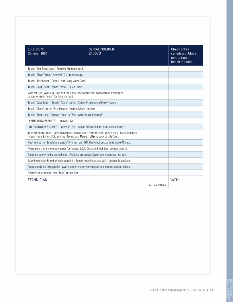
ELECTION: Summer 2005
SERIAL NUMBER: 216879
Check off as completed. Move unit to repair bench if it fails.
Touch “Exit Supervisor.” Remove Manager card.
Touch “Clear Totals.” Answer “OK” to message.
Touch “Test Count.” Check “Not Using Voter Card.”
Touch “Count Test.” Touch “Vote.” Touch “Next.”
Vote for Red, White, & Blue and then one time for the frst candidate in every race, except write in “yam” for favorite food.
Touch “Cast Ballot.” Touch “Close” on the “Select Precinct and Party” screen.
Touch “Close” on the “Pre-Election Testing Mode” screen.
Touch “Reporting.” Answer “Yes” to “Print write-in candidates?”
“PRINT LONG REPORT?”—answer “No.”
“NEED ANOTHER COPY?”—answer “No,” unless printer did not print successfully.
Tear off printer tape. Confrm machine number and 1 vote for Red, White, Blue, frst candidate in each race & yam. Fold printout facing out. Paper clip to back of this form.
Push red button & hold to count of 3 to turn unit Off. Use eject button to remove PC card.
Make sure there is enough paper for manual L&A. Close and lock both compartments.
Clean screen with dry optical cloth. Replace protective Styrofoam sheet over screen.
Examine hinges & fold privacy panels in. Relock machine at top with its specifc padlock.
Put a plastic tie through the lower holes in the privacy panels as a marker that it is done.
Remove colored dot from “foot” of machine.
TEChNICIAN: Revised 5/31/05
DATE:
EELLEECCTTIIOONN MMAANNAAGGEEMMEENNTT GGUUIIDDEELLIINNEESS 3939

Page is intentionally left blank