chapter 33: other welding processes, brazing and soldering
DESCRIPTION
Chapter 33: Other Welding Processes, Brazing and Soldering. DeGarmo’s Materials and Processes in Manufacturing. 33.1 Introduction. Other processes include some that are quite old (thermit welding) and others that are among the newest in manufacturing (laser and electron beam). - PowerPoint PPT PresentationTRANSCRIPT
Chapter 33:Other Welding Processes, Brazing and SolderingDeGarmo’s Materials and Processes in
Manufacturing
2/43
33.1 Introduction
Other processes include some that are quite old (thermit welding) and others that are among the newest in manufacturing (laser and electron beam).
Low-temperature joining methods include brazing, soldering, adhesive bonding, and the use of mechanical fasteners.
3/43
33.2 Other Welding and Cutting Processes Thermit welding Electroslag welding Electron-beam welding Laser-beam welding Laser-beam cutting Laser spot welding Flash welding
4/43
Thermit Welding (TW)
Superheated molten metal and slag are produced from an exothermic chemical reaction between a metal oxide and a metallic reducing agent.
As a mechanical mixture of about one part (by weight) finely divided aluminum and three parts iron oxide is ignited by a magnesium fuse (1150 or 2100℃ oF), it reacts as follows.
8Al + 2Fe3O4 9Fe + Al2O3 + heat (2750 or 5000℃ oF)
5/43
Thermit Welding (Cont.)
The molten iron flows by gravity into a prepared joint, providing both heat and filler metal, in the weld of steels and cast irons.
Copper, brass and bronze can be joined using a starting mixture of copper oxide and aluminum.
6/43
Electroslag Welding (ESW)
Effective process for welding thick sections of steel plate.
There is no arc involved (except to start the weld) and the electrical resistance of the metal being welded plays no part in producing the heat.
Heat is derived from the passage of electrical current through a pool of electrically conductive liquid slag (around 1750 , 3200℃ oF), then melting the edges of the pieces being joined, as well as continuously fed solid or flux-cored electrodes.
7/43
Schematic of ESW
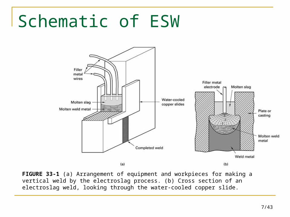
FIGURE 33-1 (a) Arrangement of equipment and workpieces for making a vertical weld by the electroslag process. (b) Cross section of an electroslag weld, looking through the water-cooled copper slide.
8/43
Electron Beam Welding (EBW)
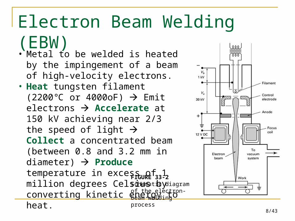
FIGURE 33-2 Schematic diagram of the electron-beam welding process
• Metal to be welded is heated by the impingement of a beam of high-velocity electrons.
• Heat tungsten filament (2200 or ℃4000oF) Emit electrons Accelerate at 150 kV achieving near 2/3 the speed of light Collect a concentrated beam (between 0.8 and 3.2 mm in diameter) Produce temperature in excess of 1 million degrees Celsius by converting kinetic energy to heat.
9/43
Examples of EBW
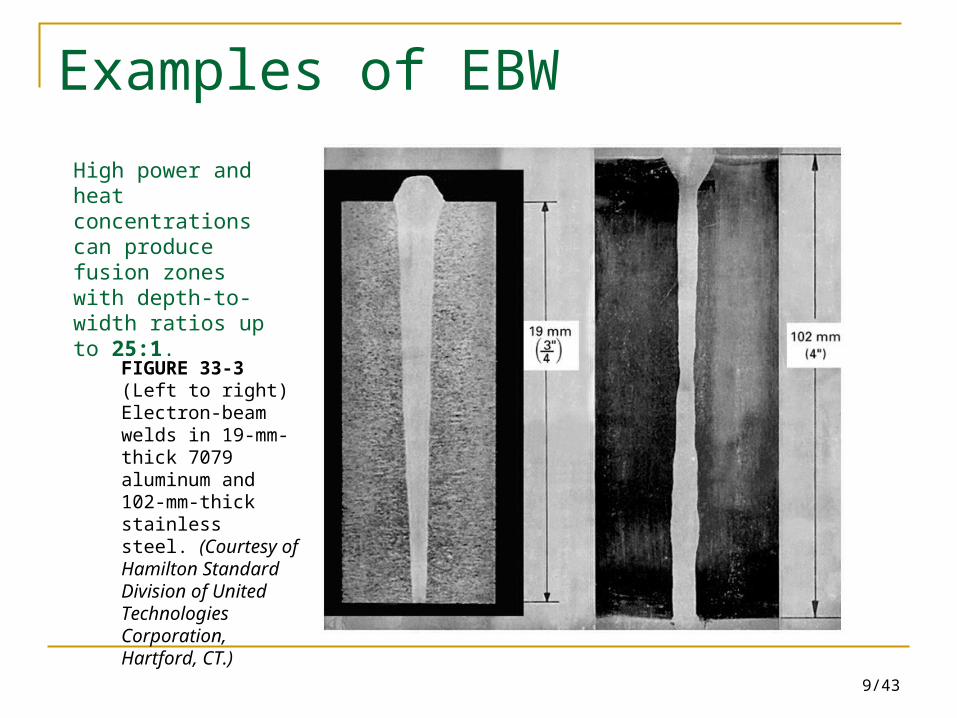
FIGURE 33-3 (Left to right) Electron-beamwelds in 19-mm-thick 7079 aluminum and 102-mm-thick stainlesssteel. (Courtesy of Hamilton StandardDivision of United TechnologiesCorporation, Hartford, CT.)
High power and heat concentrations can produce fusion zones with depth-to-width ratios up to 25:1.
10/43
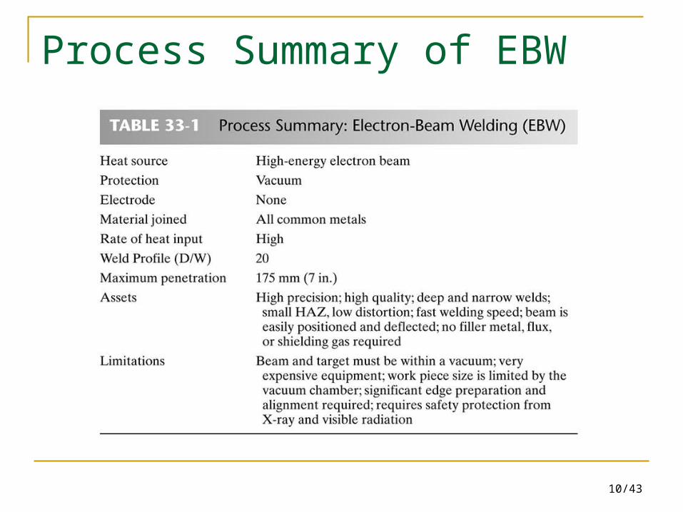
Process Summary of EBW
11/43
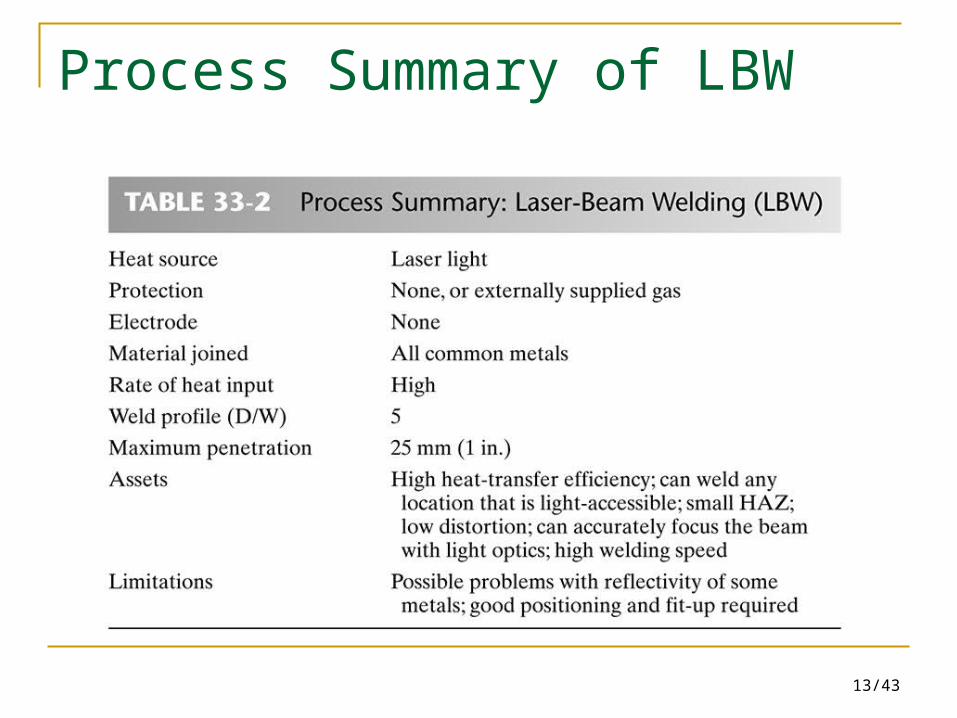
Laser-Beam Welding (LBW)
Laser beams can be used as a heat sources for welding, hole making, cutting, cladding (plating), and heat treating a wide variety of engineering metals.
For laser-beam welding, the beam of coherent light can be focused to a diameter of 0.1 to 1.0 mm, providing a power density in excess of 106 watts/mm2.
Weld with a depth-to-width ratio generally greater than 5:1.
12/43
Examples of LBW
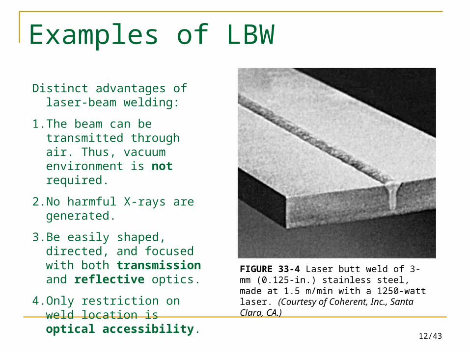
FIGURE 33-4 Laser butt weld of 3-mm (0.125-in.) stainless steel, made at 1.5 m/min with a 1250-watt laser. (Courtesy of Coherent, Inc., Santa Clara, CA.)
Distinct advantages of laser-beam welding:
1. The beam can be transmitted through air. Thus, vacuum environment is not required.
2. No harmful X-rays are generated.
3. Be easily shaped, directed, and focused with both transmission and reflective optics.
4. Only restriction on weld location is optical accessibility.
13/43
Process Summary of LBW
14/43
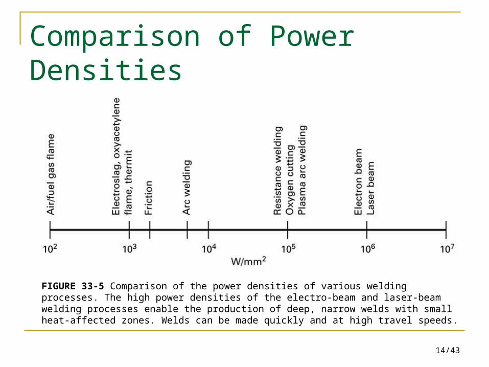
Comparison of Power Densities
FIGURE 33-5 Comparison of the power densities of various welding processes. The high power densities of the electro-beam and laser-beam welding processes enable the production of deep, narrow welds with small heat-affected zones. Welds can be made quickly and at high travel speeds.
15/43
Laser Beam Cutting (LBC)
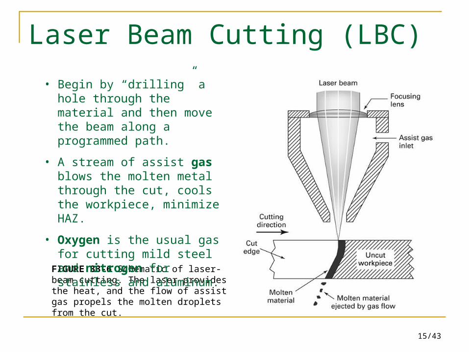
FIGURE 33-6 Schematic of laser-beam cutting. The laser provides the heat, and the flow of assist gas propels the molten droplets from the cut.
• Begin by “drilling” a hole through the material and then move the beam along a programmed path.
• A stream of assist gas blows the molten metal through the cut, cools the workpiece, minimize HAZ.
• Oxygen is the usual gas for cutting mild steel and nitrogen for stainless and aluminum.
16/43
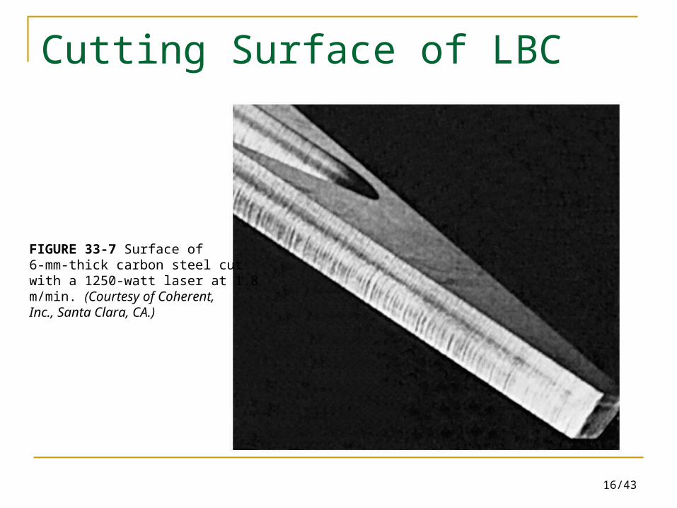
Cutting Surface of LBC
FIGURE 33-7 Surface of6-mm-thick carbon steel cutwith a 1250-watt laser at 1.8m/min. (Courtesy of Coherent,Inc., Santa Clara, CA.)
17/43
Laser Spot Welding
A small clamping force is applied to ensure contact of the workpieces, and a fine-focused beam then scan the area of the weld. As the beam is moved, molten metal flows into the hole and solidifies, forming a fusion-type nugget.
Features: Perform with access to only one side of the joint Produce no indentations with a noncontact
process.
18/43
Flash Welding (FW)
Produce butt welds between similar or dissimilar metals in solid or tubular form.
Pass electric current through the joint to provide optional preheat Withdraw welding pieces slightly forming an intense flashing arc across the gap to melt materials on both surfaces Force pieces together under high pressure (70 MPa or 10,000 psi) to expel the liquid and oxides and to upset the softened metal Turn off the electric current and the force is maintained until solidification is completed.
19/43
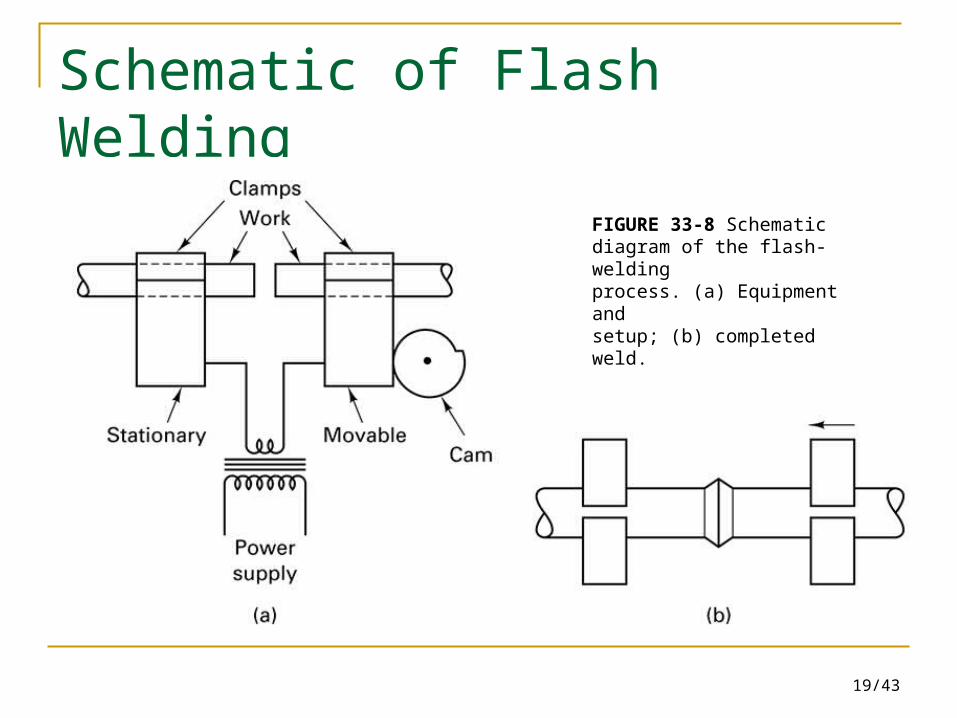
Schematic of Flash Welding
FIGURE 33-8 Schematicdiagram of the flash-weldingprocess. (a) Equipment andsetup; (b) completed weld.
20/43
33.3 Surface Modification by Welding-Related Processes Surfacing or overlaying –
process of depositing a layer of weld metal on the surface or edge of a base material of different composition base material to obtain improved resistance to wear, abrasion, heat, or chemical attack, without having to make the entire piece from an expensive material.
21/43
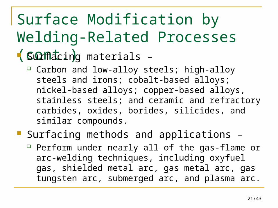
Surface Modification by Welding-Related Processes (cont.) Surfacing materials –
Carbon and low-alloy steels; high-alloy steels and irons; cobalt-based alloys; nickel-based alloys; copper-based alloys, stainless steels; and ceramic and refractory carbides, oxides, borides, silicides, and similar compounds.
Surfacing methods and applications – Perform under nearly all of the gas-flame or arc-welding
techniques, including oxyfuel gas, shielded metal arc, gas metal arc, gas tungsten arc, submerged arc, and plasma arc.
22/43
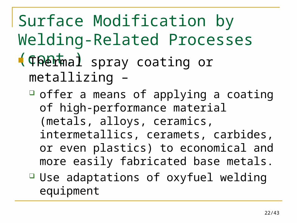
Surface Modification by Welding-Related Processes (cont.) Thermal spray coating or metallizing –
offer a means of applying a coating of high-performance material (metals, alloys, ceramics, intermetallics, ceramets, carbides, or even plastics) to economical and more easily fabricated base metals.
Use adaptations of oxyfuel welding equipment
23/43
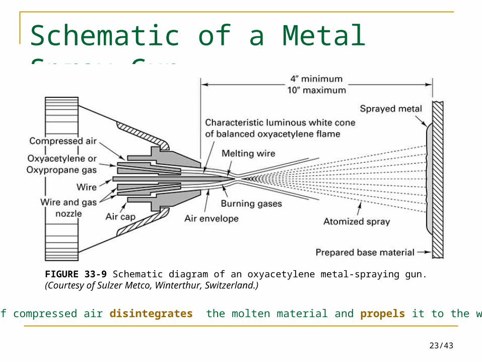
Schematic of a Metal Spray Gun
FIGURE 33-9 Schematic diagram of an oxyacetylene metal-spraying gun. (Courtesy of Sulzer Metco, Winterthur, Switzerland.)
A flow of compressed air disintegrates the molten material and propels it to the workpiece.
24/43
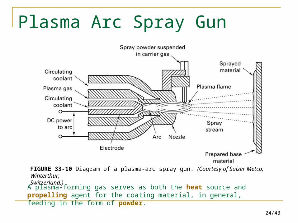
Plasma Arc Spray Gun
FIGURE 33-10 Diagram of a plasma-arc spray gun. (Courtesy of Sulzer Metco, Winterthur,Switzerland.)
A plasma-forming gas serves as both the heat source and propelling agent for the coating material, in general, feeding in the form of powder.
25/43
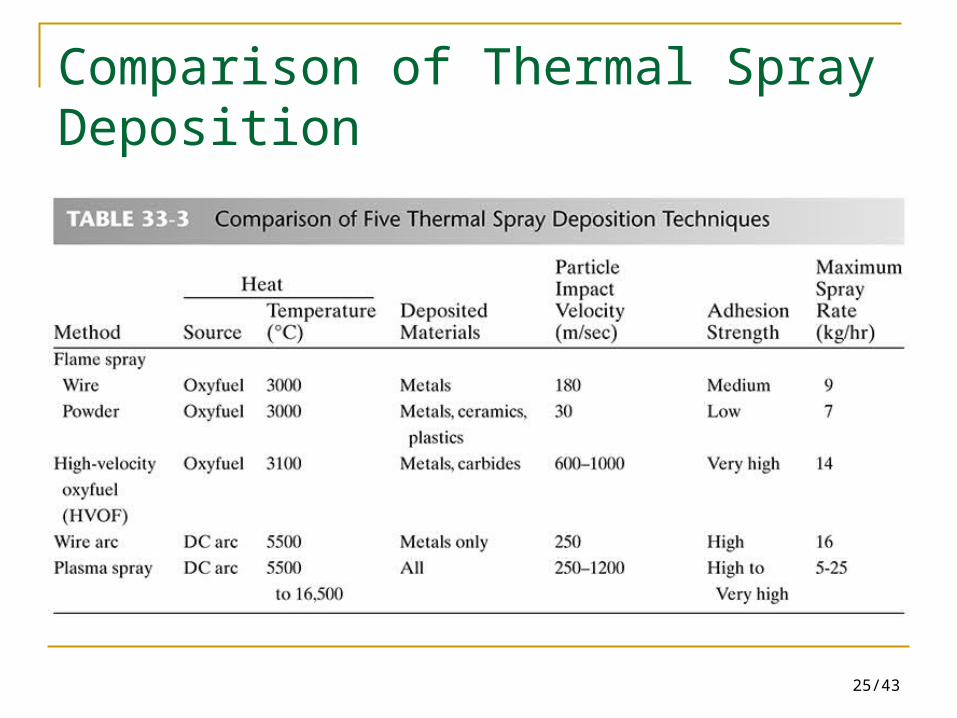
Comparison of Thermal Spray Deposition
26/43
33.4 Brazing
In brazing and soldering, the surfaces to be joined are first cleaned, the components assembled or fixed, and a low-melting-point nonferrous metal is then melted, drawn into the space between the two solids by capillary action, and allowed to solidify.
Brazing – Permanent joining of similar or dissimilar metals or
ceramics through the use of heat and a filler metal with a melting temperature above 450℃ (840oF) but below the melting point of the materials being joined.
27/43
Brazing (cont.)
Differences between brazing and welding The composition the brazing alloy is significantly
different from that of the base metal. The strength of the brazing alloy is lower than
that of the base metal. None of the base metal is melted. Bonding requires capillary action to distribute the
filler metal between the closely fitting surface of the joint.
28/43
Brazing (cont.)
Advantages for brazing process A wide range of metallic and nonmetallic materials can
be brazed; suited for joining dissimilar materials. Performed quickly and economically. Lower temperature, reduce problems associate with
HAZ, warping, and distortion; Closed assembly tolerance. Highly adaptable to automation and mass-producing
complex or delicate assemblies. A strong permanent joint is formed.
29/43
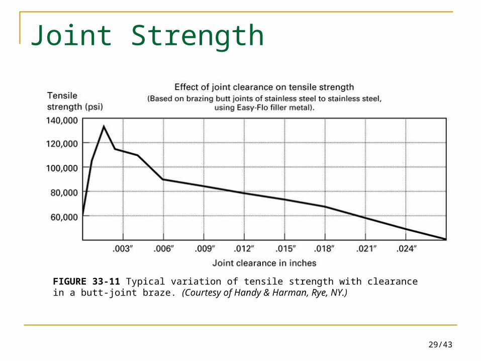
Joint Strength
FIGURE 33-11 Typical variation of tensile strength with clearance in a butt-joint braze. (Courtesy of Handy & Harman, Rye, NY.)
30/43
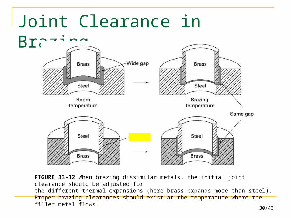
Joint Clearance in Brazing
FIGURE 33-12 When brazing dissimilar metals, the initial joint clearance should be adjusted forthe different thermal expansions (here brass expands more than steel). Proper brazing clearances should exist at the temperature where the filler metal flows.
31/43
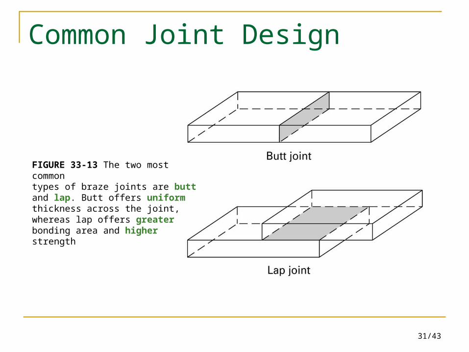
Common Joint Design
FIGURE 33-13 The two most commontypes of braze joints are butt and lap. Butt offers uniform thickness across the joint, whereas lap offers greater bonding area and higher strength
32/43
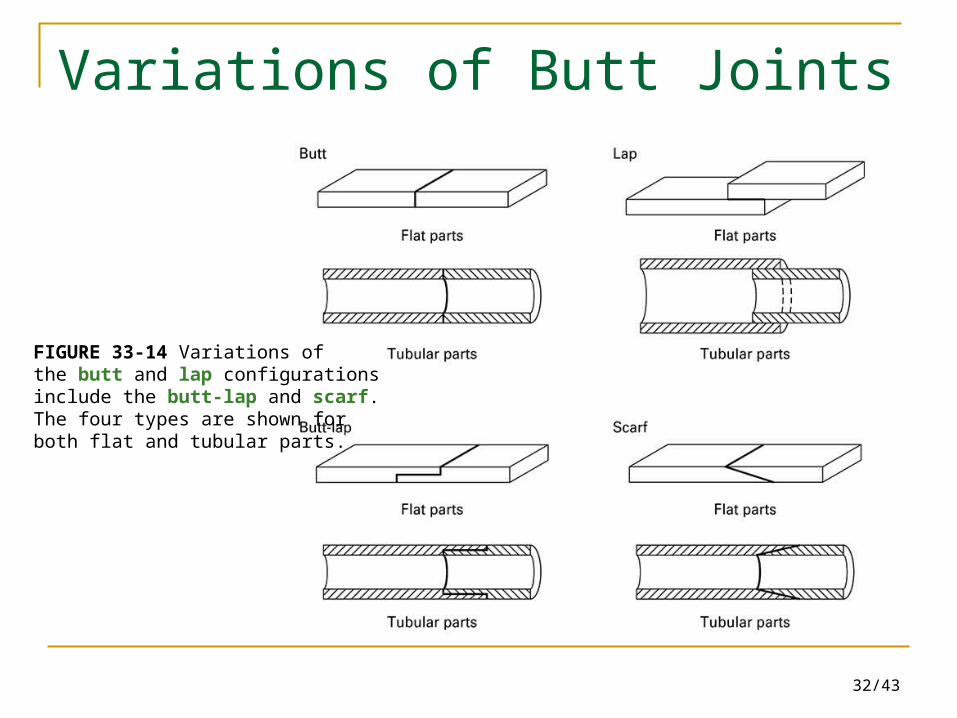
Variations of Butt Joints
FIGURE 33-14 Variations ofthe butt and lap configurationsinclude the butt-lap and scarf.The four types are shown forboth flat and tubular parts.
33/43
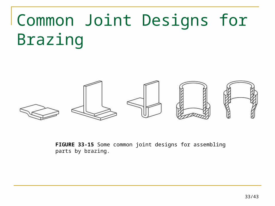
Common Joint Designs for Brazing
FIGURE 33-15 Some common joint designs for assembling parts by brazing.
34/43
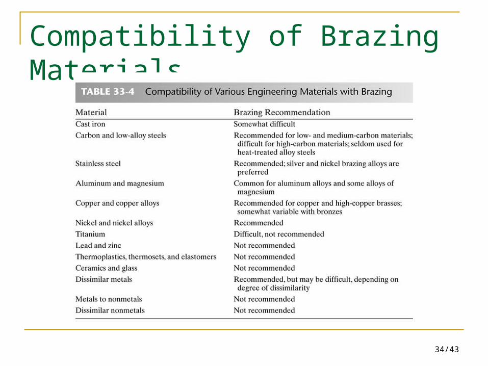
Compatibility of Brazing Materials
35/43
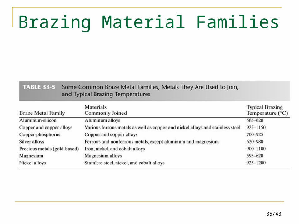
Brazing Material Families
36/43
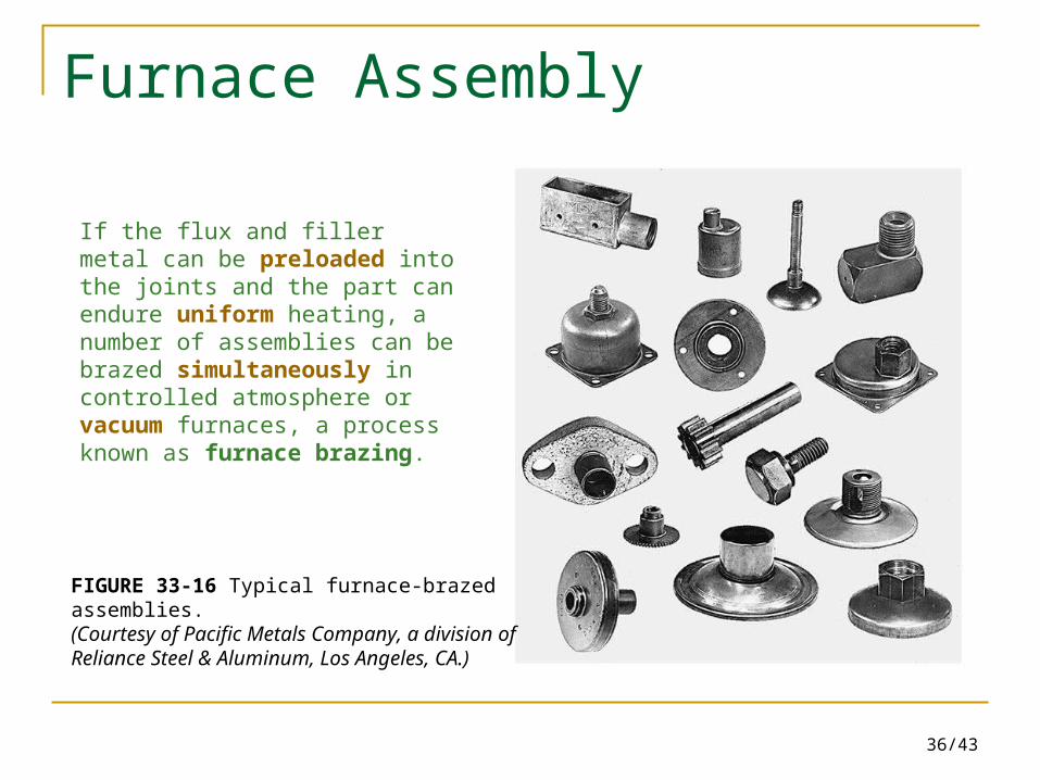
Furnace Assembly
FIGURE 33-16 Typical furnace-brazed assemblies.(Courtesy of Pacific Metals Company, a division of Reliance Steel & Aluminum, Los Angeles, CA.)
If the flux and filler metal can be preloaded into the joints and the part can endure uniform heating, a number of assemblies can be brazed simultaneously in controlled atmosphere or vacuum furnaces, a process known as furnace brazing.
37/43
Braze-Welding Process
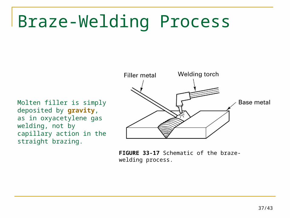
FIGURE 33-17 Schematic of the braze-welding process.
Molten filler is simply deposited by gravity, as in oxyacetylene gas welding, not by capillary action in the straight brazing.
38/43
33.5 Soldering
Soldering – a brazing-type operation where the filler metal has
a melting temperature below 450°C (840oF). Used for joining thin metals, connecting electronic
components, joining metals while avoiding exposure to high elevated temperatures, and filling surface flaws and defects.
39/43
Design of Solder Joints
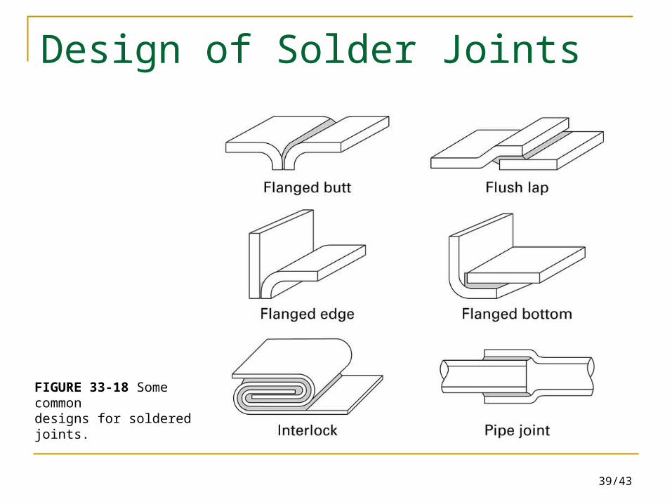
FIGURE 33-18 Some commondesigns for soldered joints.
40/43
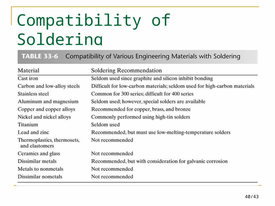
Compatibility of Soldering
41/43
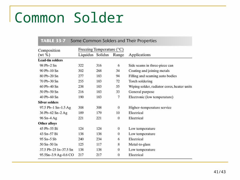
Common Solder
42/43
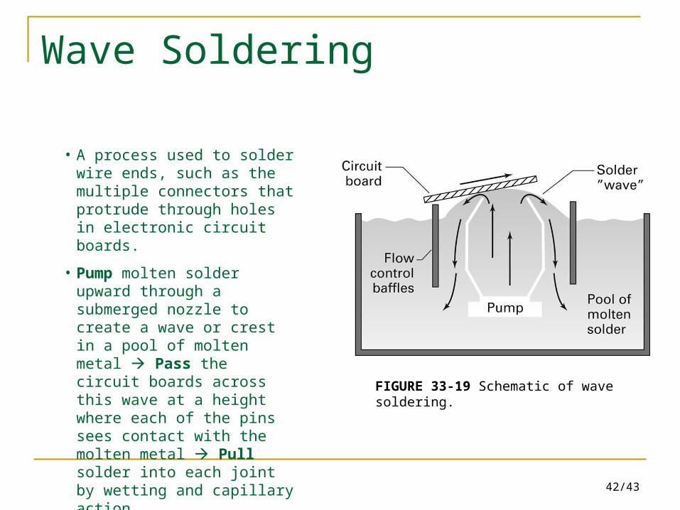
Wave Soldering
FIGURE 33-19 Schematic of wave soldering.
• A process used to solder wire ends, such as the multiple connectors that protrude through holes in electronic circuit boards.
• Pump molten solder upward through a submerged nozzle to create a wave or crest in a pool of molten metal Pass the circuit boards across this wave at a height where each of the pins sees contact with the molten metal Pull solder into each joint by wetting and capillary action.

43/43
Reference Problems
Review Questions 4 (6), 10, 12, 20, 21, 29, 34 (35), 45, 52, 55