chapter 30tyson/p121-ece_lecture11_ch30.pdf · self-inductance: a varying current in a circuit...
TRANSCRIPT

Copyright © 2012 Pearson Education Inc.
PowerPoint® Lectures for University Physics, Thirteenth Edition – Hugh D. Young and Roger A. Freedman
Lectures by Wayne Anderson
Chapter 30
Inductance

Copyright © 2012 Pearson Education Inc.
Goals for Chapter 30
• To learn how current in one coil can induce an emf in another unconnected coil
• To relate the induced emf to the rate of change of the current
• To calculate the energy in a magnetic field
• To analyze circuits containing resistors and inductors
• To describe electrical oscillations in circuits and why the oscillations decay

Copyright © 2012 Pearson Education Inc.
Introduction • How does a coil induce a
current in a neighboring coil.
• A sensor triggers the traffic light to change when a car arrives at an intersection. How does it do this?
• Why does a coil of metal behave very differently from a straight wire of the same metal?
• We’ll learn how circuits can be coupled without being connected together.

Copyright © 2012 Pearson Education Inc.
Mutual inductance
• Mutual inductance: A changing current in one coil induces a current in a neighboring coil. See Figure 30.1 at the right.
• Follow the discussion of mutual inductance in the text.
Copyright © 2012 Pearson Education Inc.
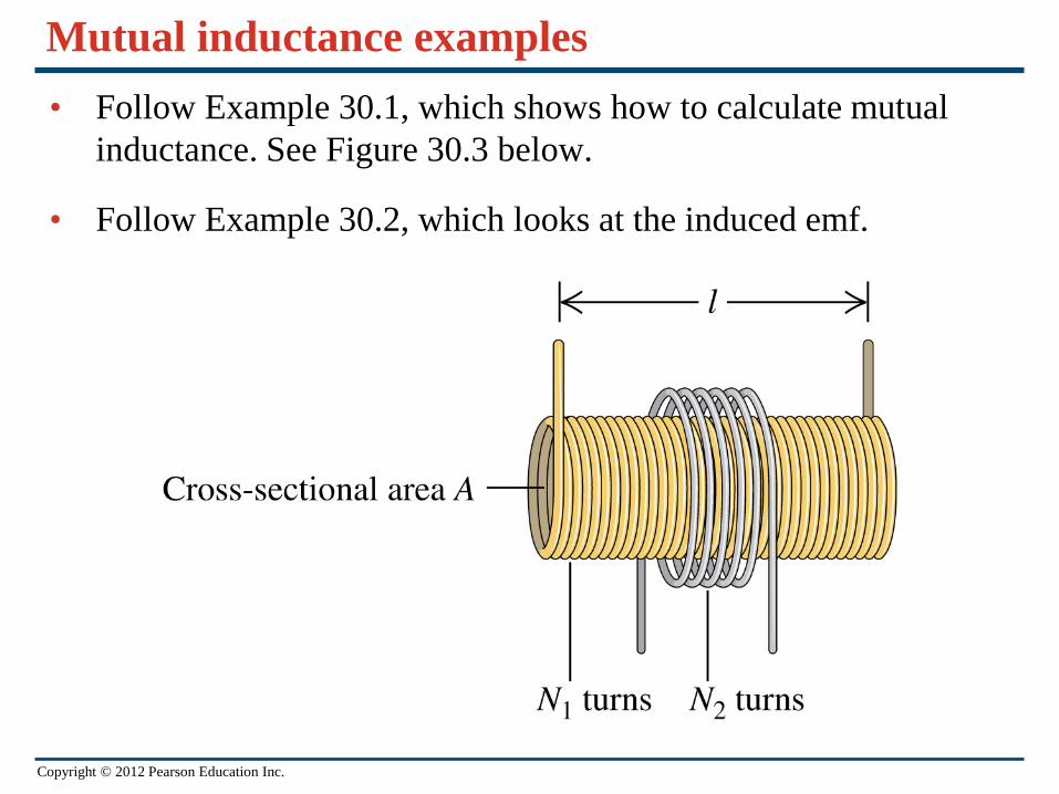
Mutual inductance examples • Follow Example 30.1, which shows how to calculate mutual
inductance. See Figure 30.3 below.
• Follow Example 30.2, which looks at the induced emf.

Copyright © 2012 Pearson Education Inc.
Self-inductance • Self-inductance: A varying current in a circuit induces an emf in
that same circuit. See Figure 30.4 below.
• Follow the text discussion of self-inductance and inductors.
Copyright © 2012 Pearson Education Inc.
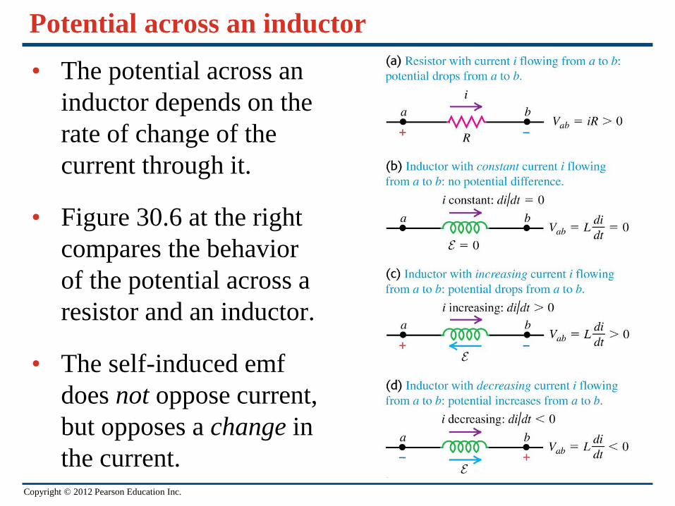
Potential across an inductor
• The potential across an inductor depends on the rate of change of the current through it.
• Figure 30.6 at the right compares the behavior of the potential across a resistor and an inductor.
• The self-induced emf does not oppose current, but opposes a change in the current.
Copyright © 2012 Pearson Education Inc.
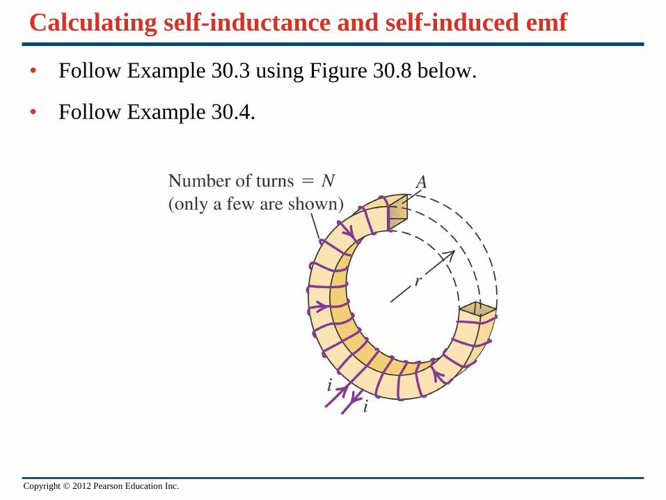
Calculating self-inductance and self-induced emf
• Follow Example 30.3 using Figure 30.8 below.
• Follow Example 30.4.
Copyright © 2012 Pearson Education Inc.
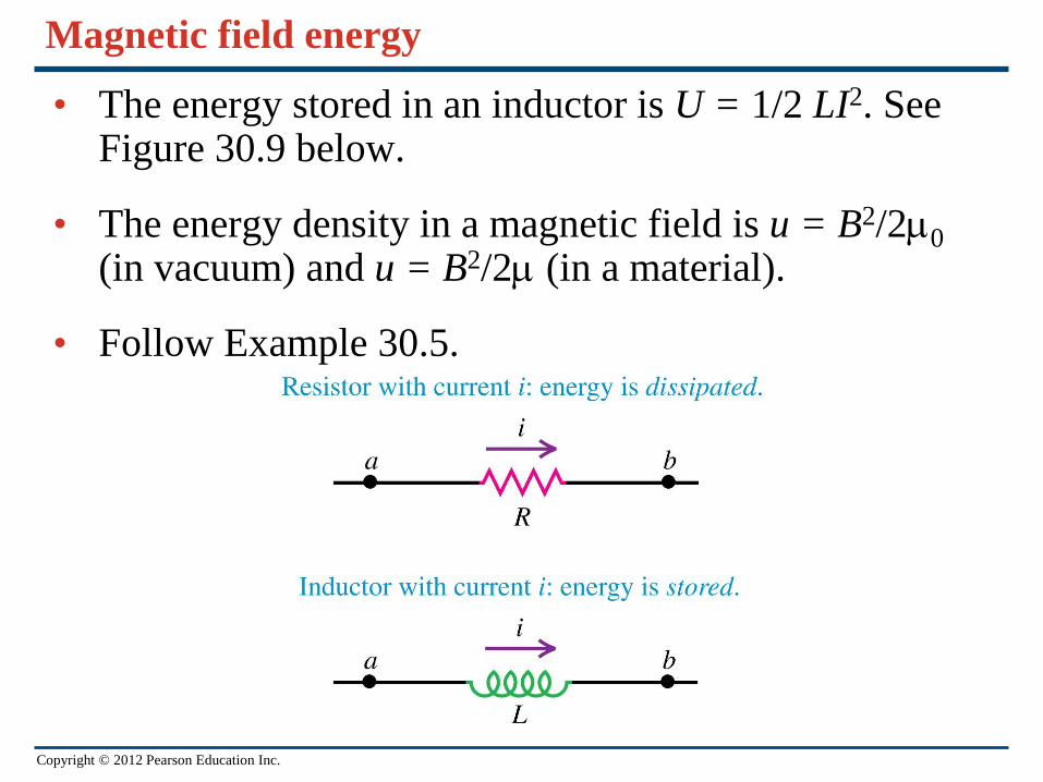
Magnetic field energy
• The energy stored in an inductor is U = 1/2 LI2. See Figure 30.9 below.
• The energy density in a magnetic field is u = B2/2µ0 (in vacuum) and u = B2/2µ (in a material).
• Follow Example 30.5.
Copyright © 2012 Pearson Education Inc.
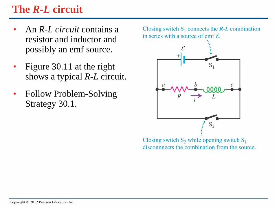
The R-L circuit
• An R-L circuit contains a resistor and inductor and possibly an emf source.
• Figure 30.11 at the right shows a typical R-L circuit.
• Follow Problem-Solving Strategy 30.1.

Copyright © 2012 Pearson Education Inc.
Current growth in an R-L circuit
• Follow the text analysis of current growth in an R-L circuit.
• The time constant for an R-L circuit is τ = L/R.
• Figure 30.12 at the right shows a graph of the current as a function of time in an R-L circuit containing an emf source.
• Follow Example 30.6.
Copyright © 2012 Pearson Education Inc.
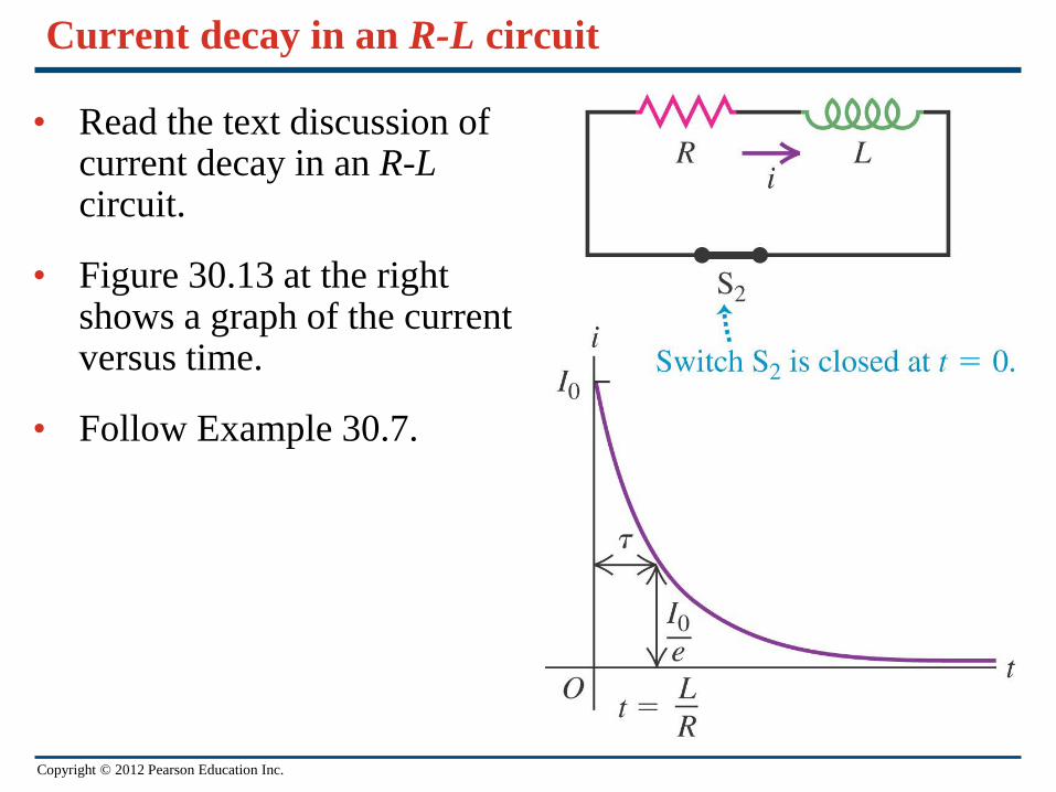
Current decay in an R-L circuit
• Read the text discussion of current decay in an R-L circuit.
• Figure 30.13 at the right shows a graph of the current versus time.
• Follow Example 30.7.
Copyright © 2012 Pearson Education Inc.
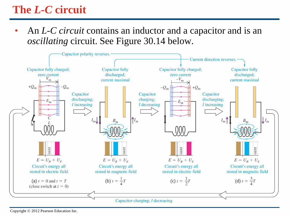
The L-C circuit
• An L-C circuit contains an inductor and a capacitor and is an oscillating circuit. See Figure 30.14 below.
Copyright © 2012 Pearson Education Inc.
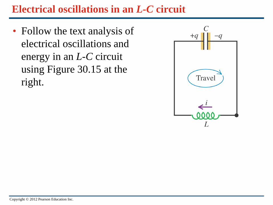
Electrical oscillations in an L-C circuit
• Follow the text analysis of electrical oscillations and energy in an L-C circuit using Figure 30.15 at the right.
Copyright © 2012 Pearson Education Inc.
Electrical and mechanical oscillations
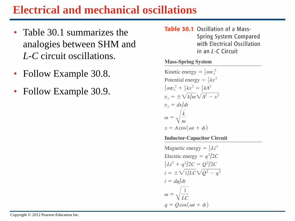
• Table 30.1 summarizes the analogies between SHM and L-C circuit oscillations.
• Follow Example 30.8.
• Follow Example 30.9.

Copyright © 2012 Pearson Education Inc.
The L-R-C series circuit
• Follow the text analysis of an L-R-C circuit.
• An L-R-C circuit exhibits damped harmonic motion if the resistance is not too large. (See graphs in Figure 30.16 at the right.)
• Follow Example 30.10.