chapter 30 inductance, electromagnetic oscillations, and...
TRANSCRIPT

Copyright © 2009 Pearson Education, Inc.
Chapter 30Inductance, Electromagnetic Oscillations, and AC Circuits

Copyright © 2009 Pearson Education, Inc.
• Mutual Inductance
• Self-Inductance
• Energy Stored in a Magnetic Field
• LR Circuits
• LC Circuits and Electromagnetic Oscillations
• LC Circuits with Resistance (LRC Circuits)
• AC Circuits with AC Source
Units of Chapter 30

Copyright © 2009 Pearson Education, Inc.
• LRC Series AC Circuit
• Resonance in AC Circuits
• Impedance Matching
• Three-Phase AC
Units of Chapter 30

Copyright © 2009 Pearson Education, Inc.
Mutual inductance: a changing current in one coil will induce a current in a second coil:
And vice versa; note that the constant M, known as the mutual inductance, is the same:
30-1 Mutual Inductance

Copyright © 2009 Pearson Education, Inc.
Unit of inductance: the henry, H:
1 H = 1 V·s/A = 1 Ω·s.
A transformer is an example of mutual inductance.
30-1 Mutual Inductance

Copyright © 2009 Pearson Education, Inc.
30-1 Mutual InductanceExample 30-1: Solenoid and coil.
A long thin solenoid of length l and cross-sectional area A contains N1 closely packed turns of wire. Wrapped around it is an insulated coil of N2 turns. Assume all the flux from coil 1 (the solenoid) passes through coil 2, and calculate the mutual inductance.

Copyright © 2009 Pearson Education, Inc.
30-1 Mutual Inductance
Conceptual Example 30-2: Reversing the coils.
How would Example 30–1 change if the coil with turns was inside the solenoid rather than outside the solenoid?

Copyright © 2009 Pearson Education, Inc.
A changing current in a coil will also induce an emf in itself:
Here, L is called the self-inductance:
30-2 Self-Inductance

Copyright © 2009 Pearson Education, Inc.
30-2 Self-Inductance
Example 30-3: Solenoid inductance.
(a) Determine a formula for the self-inductance L of a tightly wrapped and long solenoid containing N turns of wire in its length l and whose cross-sectional area is A.
(b) Calculate the value of L if N = 100, l = 5.0 cm, A = 0.30 cm2, and the solenoid is air filled.

Copyright © 2009 Pearson Education, Inc.
30-2 Self-InductanceConceptual Example 30-4: Direction of emf in inductor.
Current passes through a coil from left to right as shown. (a) If the current is increasing with time, in which direction is the induced emf? (b) If the current is decreasing in time, what then is the direction of the induced emf?

Copyright © 2009 Pearson Education, Inc.
30-2 Self-InductanceExample 30-5: Coaxial cable inductance.
Determine the inductance per unit length of a coaxial cable whose inner conductor has a radius r1 and the outer conductor has a radius r2. Assume the conductors are thin hollow tubes so there is no magnetic field within the inner conductor, and the magnetic field inside both thin conductors can be ignored. The conductors carry equal currents I in opposite directions.

Copyright © 2009 Pearson Education, Inc.
Just as we saw that energy can be stored in an electric field, energy can be stored in a magnetic field as well, in an inductor, for example.
Analysis shows that the energy density of the field is given by
30-3 Energy Stored in a Magnetic Field

Copyright © 2009 Pearson Education, Inc.
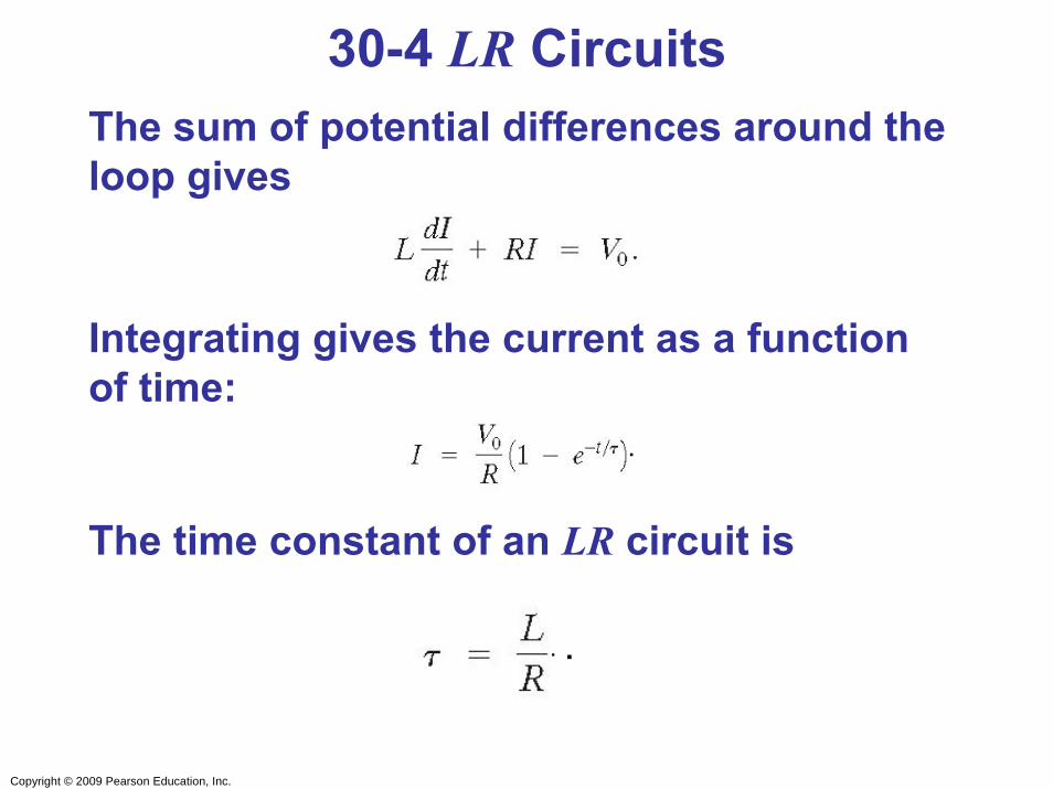
A circuit consisting of an inductor and a resistor will begin with most of the voltage drop across the inductor, as the current is changing rapidly. With time, the current will increase less and less, until all the voltage is across the resistor.
30-4 LR Circuits
Copyright © 2009 Pearson Education, Inc.
30-4 LR CircuitsThe sum of potential differences around the loop gives
Integrating gives the current as a function of time:
The time constant of an LR circuit is
.
. .

Copyright © 2009 Pearson Education, Inc.
If the circuit is then shorted across the battery, the current will gradually decay away:
30-4 LR Circuits
.

Copyright © 2009 Pearson Education, Inc.
30-4 LR CircuitsExample 30-6: An LR circuit.
At t = 0, a 12.0-V battery is connected in series with a 220-mH inductor and a total of 30-Ω resistance, as shown. (a) What is the current at t = 0? (b) What is the time constant? (c) What is the maximum current? (d) How long will it take the current to reach half its maximum possible value? (e) At this instant, at what rate is energy being delivered by the battery, and (f) at what rate is energy being stored in the inductor’s magnetic field?

Copyright © 2009 Pearson Education, Inc.
30-5 LC Circuits and Electromagnetic Oscillations
An LC circuit is a charged capacitor shorted through an inductor.

Copyright © 2009 Pearson Education, Inc.
30-5 LC Circuits and Electromagnetic Oscillations
Summing the potential drops around the circuit gives a differential equation for Q:
This is the equation for simple harmonic motion, and has solutions
..

Copyright © 2009 Pearson Education, Inc.
30-5 LC Circuits and Electromagnetic Oscillations
Substituting shows that the equation can only be true for all times if the frequency is given by
The current is sinusoidal as well:

Copyright © 2009 Pearson Education, Inc.
30-5 LC Circuits and Electromagnetic Oscillations
The charge and current are both sinusoidal, but with different phases.

Copyright © 2009 Pearson Education, Inc.
30-5 LC Circuits and Electromagnetic Oscillations
The total energy in the circuit is constant; it oscillates between the capacitor and the inductor:

Copyright © 2009 Pearson Education, Inc.
30-5 LC Circuits and Electromagnetic Oscillations
Example 30-7: LC circuit.
A 1200-pF capacitor is fully charged by a 500-V dc power supply. It is disconnected from the power supply and is connected, at t = 0, to a 75-mH inductor. Determine: (a) the initial charge on the capacitor; (b) the maximum current; (c) the frequency fand period T of oscillation; and (d) the total energy oscillating in the system.

Copyright © 2009 Pearson Education, Inc.
30-6 LC Oscillations with Resistance (LRC Circuit)
Any real (nonsuperconducting) circuit will have resistance.

Copyright © 2009 Pearson Education, Inc.
30-6 LC Oscillations with Resistance (LRC Circuit)
Now the voltage drops around the circuit give
The solutions to this equation are damped harmonic oscillations. The system will be underdamped for R2 < 4L/C, and overdamped for R2 > 4L/C. Critical damping will occur when R2 = 4L/C.

Copyright © 2009 Pearson Education, Inc.
30-6 LC Oscillations with Resistance (LRC Circuit)
This figure shows the three cases of underdamping, overdamping, and critical damping.

Copyright © 2009 Pearson Education, Inc.
30-6 LC Oscillations with Resistance (LRC Circuit)
The angular frequency for underdamped oscillations is given by
The charge in the circuit as a function of time is
.
.

Copyright © 2009 Pearson Education, Inc.
30-6 LC Oscillations with Resistance (LRC Circuit)
Example 30-8: Damped oscillations.
At t = 0, a 40-mH inductor is placed in series with a resistance R = 3.0 Ω and a charged capacitor C = 4.8 μF. (a) Show that this circuit will oscillate. (b) Determine the frequency. (c) What is the time required for the charge amplitude to drop to half its starting value? (d) What value of R will make the circuit nonoscillating?

Copyright © 2009 Pearson Education, Inc.
Resistors, capacitors, and inductors have different phase relationships between current and voltage when placed in an ac circuit.
The current through a resistor is in phase with the voltage.
30-7 AC Circuits with AC Source
ANIMATION: AC Generator

Copyright © 2009 Pearson Education, Inc.
Therefore, the current through an inductor lags the voltage by 90°.
30-7 AC Circuits with AC Source
The voltage across the inductor is given by
or
.

Copyright © 2009 Pearson Education, Inc.
30-7 AC Circuits with AC Source
The voltage across the inductor is related to the current through it:
The quantity XL is called the inductive reactance, and has units of ohms:
.

Copyright © 2009 Pearson Education, Inc.
30-7 AC Circuits with AC Source
Example 30-9: Reactance of a coil.
A coil has a resistance R = 1.00 Ω and an inductance of 0.300 H. Determine the current in the coil if (a) 120-V dc is applied to it, and (b) 120-V ac (rms) at 60.0 Hz is applied.

Copyright © 2009 Pearson Education, Inc.
Therefore, in a capacitor, the current leads the voltage by 90°.
30-7 AC Circuits with AC Source
The voltage across the capacitor is given by
.

Copyright © 2009 Pearson Education, Inc.
30-7 AC Circuits with AC Source
The voltage across the capacitor is related to the current through it:
The quantity XC is called the capacitive reactance, and (just like the inductive reactance) has units of ohms:
.

Copyright © 2009 Pearson Education, Inc.
30-7 AC Circuits with AC SourceExample 30-10: Capacitor reactance.
What is the rms current in the circuit shown if C = 1.0 μF and Vrms = 120 V? Calculate (a) for f = 60 Hz and then (b) for f = 6.0 x 10⁵ Hz.

Copyright © 2009 Pearson Education, Inc.
30-7 AC Circuits with AC Source
This figure shows a high-pass filter (allows an ac signal to pass but blocks a dc voltage) and a low-pass filter (allows a dc voltage to be maintained but blocks higher-frequency fluctuations).

Copyright © 2009 Pearson Education, Inc.
Analyzing the LRC series AC circuit is complicated, as the voltages are not in phase – this means we cannot simply add them. Furthermore, the reactances depend on the frequency.
30-8 LRC Series AC Circuit

Copyright © 2009 Pearson Education, Inc.
We calculate the voltage (and current) using what are called phasors – these are vectors representing the individual voltages.
Here, at t = 0, the current and voltage are both at a maximum. As time goes on, the phasors will rotate counterclockwise.
30-8 LRC Series AC Circuit

Copyright © 2009 Pearson Education, Inc.
Some time t later, the phasors have rotated.
30-8 LRC Series AC Circuit

Copyright © 2009 Pearson Education, Inc.
The voltages across each device are given by the x-component of each, and the current by its x-component. The current is the same throughout the circuit.
30-8 LRC Series AC Circuit

Copyright © 2009 Pearson Education, Inc.
We find from the ratio of voltage to current that the effective resistance, called the impedance, of the circuit is given by
30-8 LRC Series AC Circuit

Copyright © 2009 Pearson Education, Inc.
30-8 LRC Series AC CircuitThe phase angle between the voltage and the current is given by
The factor cos φ is called the power factor of the circuit.
or

Copyright © 2009 Pearson Education, Inc.
30-8 LRC Series AC Circuit
Example 30-11: LRC circuit.
Suppose R = 25.0 Ω, L = 30.0 mH, and C = 12.0 μF, and they are connected in series to a 90.0-V ac (rms) 500-Hz source. Calculate (a) the current in the circuit, (b) the voltmeter readings (rms) across each element, (c) the phase angle φ, and (d) the power dissipated in the circuit.
Copyright © 2009 Pearson Education, Inc.
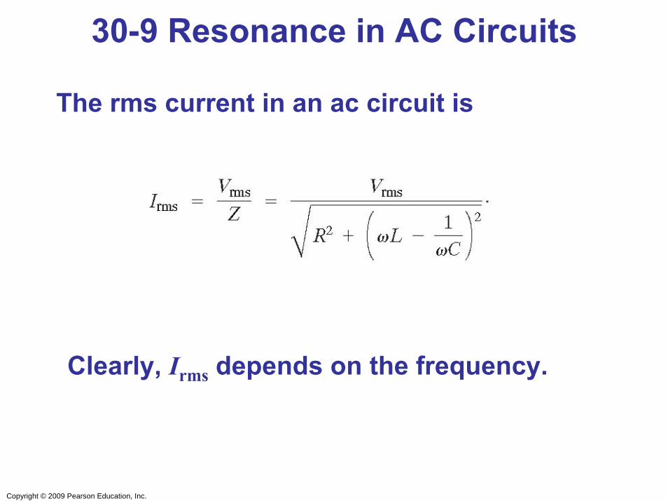
The rms current in an ac circuit is
Clearly, Irms depends on the frequency.
30-9 Resonance in AC Circuits

Copyright © 2009 Pearson Education, Inc.
We see that Irms will be a maximum when XC = XL; the frequency at which this occurs is
f0 = ω0/2π is called the resonant frequency.
30-9 Resonance in AC Circuits

Copyright © 2009 Pearson Education, Inc.
30-10 Impedance MatchingWhen one electrical circuit is connected to another, maximum power is transmitted when the output impedance of the first equals the input impedance of the second.
The power delivered to the circuit will be a minimum when dP/dt = 0; this occurs when R1 = R2.
Copyright © 2009 Pearson Education, Inc.
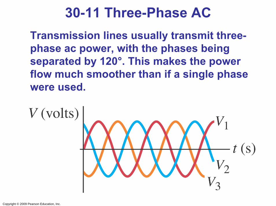
30-11 Three-Phase ACTransmission lines usually transmit three-phase ac power, with the phases being separated by 120°. This makes the power flow much smoother than if a single phase were used.

Copyright © 2009 Pearson Education, Inc.
30-11 Three-Phase AC
Example 30-12: Three-phase circuit.
In a three-phase circuit, 266 V rms exists between line 1 and ground. What is the rms voltage between lines 2 and 3?

Copyright © 2009 Pearson Education, Inc.
• Mutual inductance:
• Self-inductance:
• Energy density stored in magnetic field:
Summary of Chapter 30

Copyright © 2009 Pearson Education, Inc.
Summary of Chapter 30• LR circuit:
• Inductive reactance:
• Capacitive reactance:
.
.

Copyright © 2009 Pearson Education, Inc.
Summary of Chapter 30
• LRC series circuit:
• Resonance in LRC series circuit:
.