chapter 3: sudas: mmwave relaying for 5g outdoor-to-indoor ...derrick/ch3_sudas.pdf · chapter 3...
TRANSCRIPT

Chapter 3
SUDAS: mmWave relaying for 5Goutdoor-to-indoor communications
Marco Breiling, Derrick Wing Kwan Ng, Christian Rohde,Frank Burkhardt and Robert Schober
3.1 Introduction
The spatial degrees of freedom offered by multiple antennas at transmitters andreceivers of wireless communication systems facilitate a trade-off between multi-plexing gains and diversity gains [1–3], which provides a high flexibility in resourceallocation. A wireless point-to-point link with M transmit and N receive antennasconstitutes an M -by-N multiple-input multiple-output (MIMO) communication sys-tem. In particular, under certain mild conditions [1–3], the ergodic capacity of anM -by-N MIMO fading channel increases practically linearly with min {M , N } for afixed transmit power and bandwidth. Therefore, MIMO has attracted a lot of researchinterest over the past decades, as it enables significant performance and throughputgains. Unfortunately, the signal processing complexity required in MIMO receiversand the small number of receive antennas that a wireless mobile device can supportlimit the potential MIMO gain in practice. As an alterative, the concept of cooperativecommunication has been proposed for wireless networks as an effective technique forrealizing the MIMO performance gains. The basic idea of cooperative communicationis to enable multiple single-antenna terminals of a multiuser (MU) system to sharetheir antennas to create a virtual MIMO (VMIMO) system [4, 5]. In this context,user cooperation, base station (BS) cooperation, and relaying have been proposed inthe literature for implementation of cooperative communications. Theoretically, BScooperation and user cooperation are able to provide huge performance gains, whencompared to non-cooperative networks. However, the required information exchangebetween BSs via backhaul links [6] and the information exchange between users viawireless channels make these options less attractive in practice. In contrast, coop-erative relaying with dedicated relays requires significantly less signaling overheadand allows for low-cost implementations while achieving significant coverage exten-sion, diversity gains, and throughput gains compared to non-cooperative transmission.Therefore, cooperative relaying has attracted significant interest from both academiaand industry in the last few years.
In practice, relays can transmit and receive signals at the same time and overthe same frequencies, which is known as full-duplex (FD) relaying [7–9]. However,
72 Advanced relay technologies in next generation wireless communications
implementing such FD relays requires precise and expensive hardware componentswhich may not be desirable and cost effective. Alternatively, relays may operate ina half-duplex manner [10–27], i.e., transmission and reception at relays are sepa-rated in either time or frequency. Such relays are also known as cheap relays in theliterature due to their low hardware complexity. Different relaying strategies suchas amplify-and-forward (AF), compress-and-forward (CF), and decode-and-forward(DF) protocols have been proposed in the literature [10–27]. There is no uniformlyoptimal relaying protocol, and each protocol can outperform the others, dependingon the system configuration. Nevertheless, AF is particularly appealing for practicalimplementation, as the relays only amplify and linearly process the received signalwhich leads to low-complexity transceiver designs. More importantly, AF relays aretransparent to the adaptive modulation techniques that are typically employed at theBSs. For these reasons, AF was selected as one of the possible relaying modes in IEEE802.16j (mobile multihop relay) and is being proposed for the fourth generation (4G)Long-Term Evolution (LTE) Advanced systems. Despite the significant advances incommunication researches in the past decades, the data rate of current 4G systemsis still limited, especially for outdoor-to-indoor communication. Besides, it is fore-seen that existing network architectures may become a bottleneck in the developmentof next generation communication. Thus, an effective system architecture to assistoutdoor-to-indoor communication is needed.
The remainder of this chapter is organized as follows. In Section 3.2, we providea brief introduction to next generation communication systems. In particular, wediscuss three existing potential technologies for realizing the goals of next generationcommunication systems. In Section 3.2.3, we propose a novel shared user-equipmentside distributed antenna system (SUDAS) to assist outdoor-to-indoor communicationwhich can effectively improve the system data rate. Then, in Section 3.3, practicalimplementation details of the proposed system are discussed. Sections 3.4 and 3.5present the mathematical model and numerical performance results for the proposedsystem, respectively. Finally, in Section 3.6, we discuss some future research andimplementation challenges for the designed system.
3.2 5G communication systems
High energy efficiency, low communication latency, high spectral efficiency, and costeffectiveness are the primary goals of the fifth generation (5G) mobile communicationsystems [28–32]. In particular, a target data rate of 10 Gbit/s per device is expected forboth uplink and downlink communications. The data rate originally envisaged for 4Gmobile communication standards was 1 Gbit/s, and the LTE-A Release 10 standardextended this target to 3 Gbit/s. The ambitious goal of 5G will enable the downloadof high-definition (HD) movies within seconds and will offer very high data rates tomany users simultaneously. The tenfold increase in the required data rate from 4G to5G is one of the key performance indicators specified by the European Commissionfor 5G research within the Horizon 2020 programme. However, with existing tech-nologies, it appears very difficult to reach such high data rates even under favorableconditions. Currently, three technologies are considered as top candidates for realizing

SUDAS: mmWave relaying for 5G outdoor-to-indoor communications 73
(Macro- orsmall-cell)
basestation
UE
f UHF
f UHF
Figure 3.1 A massive MIMO BS serving a UE inside a building in theultra-high-frequency (UHF) band, fUHF
the 5G goals: massive MIMO, small cells, and the use of unlicensed millimeter wave(mmWave) bands. We will show in the sequel that it is highly questionable whetherthese technologies alone are able to reach the elusive goal of 10 Gbit/s.
3.2.1 Massive MIMO
In the past decades, MIMO has been implemented in modern communication sys-tems for providing high-speed data rate communication services due to its potential toimprove spectral efficiency [1–3]. Especially, massive MIMO technology, where a BSis equipped with a very large number of antennas to serve a comparatively small num-ber of users [33–36], is considered as a potential candidate for achieving the 10 Gbit/sdata rate target in 5G, cf. Figure 3.1. However, state-of-the-art smartphones are typ-ically equipped with only two receive antennas which limit the spatial multiplexinggain offered by MIMO. In practice, some expensive user-equipments (UEs) might pos-sess even up to four internal antennas. Yet, deploying more than four receive antennasat each UE may not be realistic due to the limited physical size of mobile receivers.Thus, despite the use of massive MIMO, at most four spatial streams can be exploitedsimultaneously for increasing the data rate of a UE. On the other hand, with carrieraggregation, a maximum of 200 MHz of licensed spectrum [37] can be created for asingle mobile network operator (MNO) with today’s technology. In other words, a totalof 50 bit/s/Hz spectral efficiency is required to meet the 10 Gbit/s requirement. Witha maximum of four spatial streams per UE offered by massive MIMO, 12.5 bit/s/Hzper spatial stream is needed which leads to a minimum required signal-to-noise ratio(SNR) of 38 dB. Besides, the use of at least 16384-quadrature amplitude modulation(QAM) in each stream is needed for achieving the required spectral efficiency. How-ever, the computational complexity for information decoding at the receiver growsexponentially with the size of the constellation, and it is challenging to implementsuch decoders for real-time applications at a reasonable cost.
3.2.2 Small cells and mmWaves
The concept of small cells, e.g., femtocells, has been proposed as a networkarchitecture for reducing the network power consumption and extending service

74 Advanced relay technologies in next generation wireless communications
Room 2
Room 1
Room 3
Room 4
UE
Small cell 3
Small cell 1
Small cell 4
Small cell 2
Optical fiber
FTTHrouter
Tobackbonenetwork
fmm
Figure 3.2 An indoor environment equipped with multiple small cells in everyroom. The small-cell BSs operate in the mmW frequency band, fmm
coverage, cf. Figure 3.2. Thanks to the very large available bandwidth for wire-less communication in the mmWave range, e.g., ∼7 GHz of bandwidth in the 60 GHzbands, it appears realistic to deliver 10 Gbit/s from a small-cell BS indoors to a UEover a short distance. However, the bottleneck now becomes the backhauling of thedata from a service provider to the indoor small-cell BS. In general, the last mile con-nection from a backbone network to the terminal users at homes cannot support suchhigh data rates, except if optical fibers are deployed, which is known as fiber-to-the-home (FTTH). However, the cost of deploying FTTH for all home users is prohibitive.For instance, the cost of equipping every building (not home!) with FTTH in Germanyis estimated to be around 67 billion a [38]. Moreover, most non-business buildingsdo not possess an internal optical fiber infrastructure or a wired ethernet for furtherdistribution of the data received from FTTH to the UEs. Furthermore, as mmWavesignals are heavily blocked by walls, a small-cell BS transmitting in the mmWavebands would be required in all rooms of a building, cf. Figure 3.2. Hence, extra costsin connecting each room of each building must be added on top of the 67 billion a,and these tremendous costs make this a less attractive option for service providers forrealizing the goals of 5G.
Another potential difficulty in utilizing the mmWave bands for communicationis finding a suitable location for installing a small-cell BS such that a line-of-sight(LOS) to all UEs is available. Without such a LOS connection, exploiting mmWavelinks for wireless communication is hardly possible. Observe that if a small-cell BSbelongs to a single MNO, the envisaged high data rate is only available to the UEs inthe small cell which are associated with this MNO. In order to allow different UEsassociated with different MNOs to enjoy high data rate services, the small-cell BSmust be neutral with regard to the MNO which is not the case for the small-cell BSs onthe market.

SUDAS: mmWave relaying for 5G outdoor-to-indoor communications 75
3.2.3 Combinations of massive MIMO and mmWave
Recently, different approaches for utilizing a combination of massive MIMO andmmWave have been proposed. Basically, these approaches can be divided into twocategories, and we summarize the corresponding disadvantages in the following:
● Backhauling of small cells by massive MIMO over mmWave– The problem of this scheme is the high penetration loss of building walls
from outdoor to indoor. Specifically, high propagation losses are expectedover longer distances at mmWave frequencies.
– A small-cell BS is required in each room and cannot be shared by differentMNOs simultaneously.
● Exploiting massive MIMO for communication to UEs in mmWave band– The high penetration loss of walls renders this approach for outdoor use only,
i.e., outdoor-to-indoor communication via mmWave may not be supported.– A large number of backhauling BSs are needed in order to provide suffi-
cient service coverage for small-cell BSs. Specifically, a LOS connection isrequired from any UE location to at least one BS at any time.
The combination of massive MIMO and small-cell schemes has limited potential toimprove the system performance as long as their operation is limited to the high-frequency unlicensed mmWave bands. Since both licensed and unlicensed bands areavailable to the service providers, it is reasonable to utilize both spectra to meetthe stringent data rate requirements of 5G which motivates our proposed design inthe next section. In the last decade, most of the data rate improvement in mobilecommunication systems was due to the use of MIMO with an increasing number ofantennas [4–42]. However, only a small number of UHF antennas can be integratedinto a UE which limits the MIMO gain for improving the spectral efficiency. On theother hand, mmWave band communication facilitates small antenna sizes and pro-vides a huge bandwidth for achieving high data rate communication. Yet, mmWavecommunication suffers from very difficult propagation conditions [43] compared toUHF. Therefore, we propose a system architecture, which efficiently combines theadvantages of MIMO over a mobile UHF band channel with its favorable propagationconditions and mmWave with its large bandwidth. Our novel architecture is derivedfrom the idea of VMIMO [4, 39, 40]. It extends the VMIMO concept to the use ofmmWave for relaying the MIMO signals transmitted in the UHF band, and to sharingan infrastructure between multiple UEs and multiple MNOs. VMIMO is also knownas cooperative MIMO, distributed MIMO, and virtual antenna arrays [4, 39]. A vari-ant of VMIMO, coordinated multi-point (CoMP), has already been implemented inLTE-A at the BS-side, where the received signals are relayed or forwarded to oneentity (e.g., a joint signal processing unit) over the backhauling network [40–42].
3.2.4 SUDAS – overview
The ambitious data rate target of 10 Gbit/s for the 5G standard is elusive despite theuse of advanced air interface technologies such as massive MIMO, small cells, andmmWave communication links. In order to achieve this high target data rate for UEs

76 Advanced relay technologies in next generation wireless communications
1
Signals relayed to/fromthe UE by relay nodes #1,
2, and 3
mmWave band Mobile bands (UHF)
BS transmits/receives a single
MIMO signal
2
f f
3
Figure 3.3 Spectrum occupation in the mmWave band and mobile bands (UHF):a single VMIMO carrier in the mobile bands is relayed to multiplenon-overlapping signals in the mmWave band
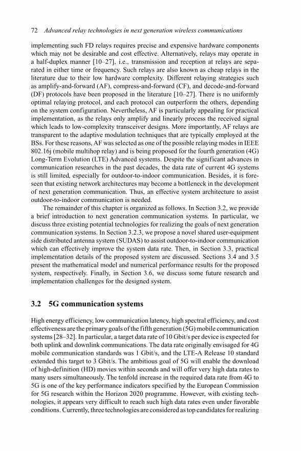
inside a building, we propose in this section for 5G to employ an infrastructure ofmany low-price relay nodes installed in fixed indoor locations. These nodes relaysignals received from the BS in a mobile UHF band via non-overlapping mmWavelinks to the UE, and vice versa, cf. Figure 3.3. We refer to this scattered infrastructureas a SUDAS [44]. The proposed relaying scheme is limited to only two hops, namelybetween the BS and the relay nodes, and between the relay nodes and the UE. Thissimplification allows a low end-to-end latency, and it avoids the significant overheadneeded for exchanging routing information. In particular, each relay is called a sharedUE-side distributed antenna component (SUDAC) in the proposed SUDAS. In prac-tice, such SUDACs could be integrated into many devices with continuous powersupply, including electrical outlets (cf. Figure 3.4), lamps, and light outlets or otherdevices that carry machine-type-communication (MTC) circuits in the future, suchas TV sets and fridges. Besides, the SUDACs are dedicated low-cost devices andscattered in a room. In the following sections, we discuss:
● Working principle of SUDAS● Potential application scenarios● Implementation details● Challenges in SUDAS
3.2.5 SUDAS – working principle
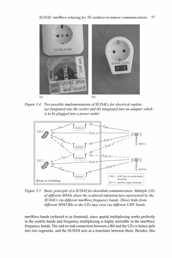
Figure 3.5 illustrates the working principle of the proposed SUDAS. All links in themobile bands from the BS of MNO “A” utilize the same frequency resource fUHF,A inthe UHF range. Besides, the mmWave links employ the orthogonal frequency bandsfmm,i, ∀i ∈ {1, . . . , M }, where M is the number of SUDACs. The SUDAS forms ascattered infrastructure which is in contrast to the centralized infrastructure realizedby deploying one small-cell BS per room. As shown in Figure 3.5, the SUDAS is notonly shared among all UEs in a room but also possibly shared between multiple BSsassociated with different MNOs. Because of the high attenuation of stone walls inthe mmWave bands, multiple SUDASs located in different rooms do hardly interferewith each other. Therefore, extensive frequency reuse can be deployed in a networkwith different SUDASs.
The SUDAS concept is particularly promising because it translates spatial multi-plexing in the mobile bands (referred to as backend) into frequency multiplexing in the
SUDAS: mmWave relaying for 5G outdoor-to-indoor communications 77
(a) (b)
Figure 3.4 Two possible implementations of SUDACs for electrical outlets:(a) integrated into the socket and (b) integrated into an adapter whichis to be plugged into a power outlet
UE 2
SUDAC
SUDACSUDAC
Room in a building
UE 1
SUDAC
SUDAC
SUDACfmm, 1 fUHF, A
fmm, 2fmm, 3
fmm, 5
fmm, 4
UHF links in mobile bands(backend)mmWave links (frontend)
MNO A
MNO B
fUHF, A
fUHF, A
fUHF, A
fUHF, B
fUHF, B
fUHF, B
Figure 3.5 Basic principle of a SUDAS for downlink communication. Multiple UEsof different MNOs share the scattered infrastructure represented by theSUDACs via different mmWave frequency bands. Direct links fromdifferent MNO BSs to the UEs may exist via different UHF bands
mmWave bands (referred to as frontend), since spatial multiplexing works perfectlyin the mobile bands and frequency multiplexing is highly desirable in the mmWavefrequency bands. The end-to-end connection between a BS and the UEs is hence splitinto two segments, and the SUDAS acts as a translator between them. Besides, this

78 Advanced relay technologies in next generation wireless communications
does not preclude the existence of direct links between the BS and the UEs which canbe further exploited to improve the VMIMO gain. An advantageous of the SUDACsis that they do not need to carry out information decoding. They simply forwardthe received signal which will be decoded at the UE (downlink) or the BS (uplink).Similarly, MIMO spatial multiplexing precoding is carried out only at the BS and theUEs, respectively. The SUDACs can hence operate in either an AF or a CF manner.Since signal reception and transmission at each SUDAC have a large frequency sep-aration (one in the UHF band and the other one in the mmWave band), both can takeplace simultaneously.1 Different from traditional relaying systems, a SUDAS utilizesboth a licensed and an unlicensed frequency band in parallel. As the spectrum in thelicensed mobile bands is scarce and costly, its efficient use is a major concern andshould be maximized. On the contrary, in the very wide unlicensed mmWave band,high spectral efficiency is not needed as the unlicensed band is virtually free of cost.As a result, SUDAS is able to exploit these properties for improving the system per-formance. Furthermore, a SUDAS offers markedly higher degrees of spatial diversitythan a small-cell BS due to its scattered nature. This is particularly pronounced in themmWave band. For instance, a human body may completely shadow a mmWave linkbetween a small-cell BS and a UE. However, it is rather unlikely that the links to allSUDACs in a room will be shadowed simultaneously. Also, the SUDAS infrastructurecan be shared between multiple UEs and multiple MNOs, which is not possible fortraditional relaying networks.
3.2.6 SUDAS – application scenarios
The main application scenario for the utilization of a SUDAS is outdoor-to-indoorcommunication, i.e., the transmitter is located outdoors while the receivers are insidebuildings, such as a living room or a large open-plan office. In fact, since mostmobile traffic is consumed indoors (especially at home in the evening [45]) and whilecommuting, such SUDAS installations would cover the most important mobile usecases. SUDACs could be integrated into electrical outlets and many electrical devices,e.g., Figure 3.4. Therefore, having eight SUDACs or more per room appears to be arealistic scenario. Besides providing very high data rates for one UE, a SUDAS is alsoable to the improve MU-MIMO performance to support high-speed communicationfor multiple simultaneous users. In the following, we discuss three different practicalapplication scenarios for which SUDAS is able to improve the system performance.
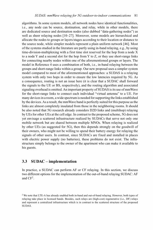
3.2.6.1 Scenario 1A SUDAS could enable the data rates and spectral efficiencies that future broadcastsystems such as LTE-multimedia broadcast multicast services strive to achieve inorder to deliver ultra-HD television content to fixed TV sets (which act as a receive-only UE) with indoor antennas (Figure 3.6). To achieve these goals, the use of MIMO
1 In practice, the time delay incurred by frequency up-/down-conversion at each SUDAC is much shorterthan the delay spread of the channel. Thus, the time delay introduced by the frequency conversion does nothave a large impact on the system performance.
SUDAS: mmWave relaying for 5G outdoor-to-indoor communications 79
TV set
SUDAC
SUDACSUDAC
UE
SUDAC
SUDAC
SUDACfmm, 1 fUHF, A
fmm, 2fmm, 3
fmm, 5
fmm, 4
UHF links in mobile bands(backend)mmWave links (frontend)
BS
MIMOTV
transmitter
fUHF, A
fUHF, A
fUHF, A
fUHF, B
fUHF, B
fUHF, B
Figure 3.6 A SUDAS used for TV broadcast signal reception with a MIMO TVtransmitter and shared by a UE for mobile reception. The TV set canuse internal or external indoor antennas
Other room in the samebuildingRoom in a building
SUDAC
SUDAC
SUDAC
HeNB
Opticalfiber
SUDAC
SUDAC
f mm, 1 fmm
, 1
f mm, 2
fmm, 2
fmm, 3
fUHF
fUHF
fUHF
fUHF
UE
Figure 3.7 SUDAS in two rooms used for connecting a UE to an HeNB in anotherroom
is indispensable and the multiplexing gain brought to the TV set could be increasedby the proposed SUDAS.
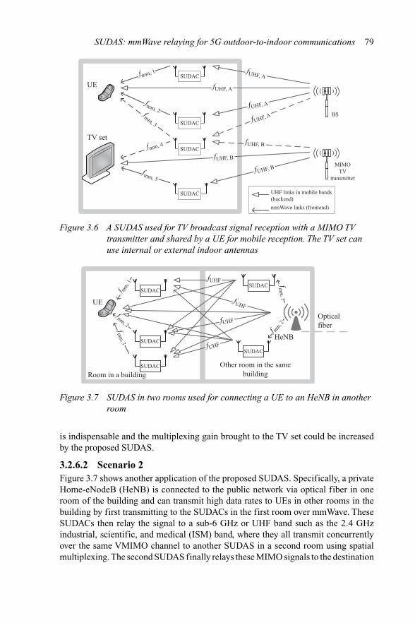
3.2.6.2 Scenario 2Figure 3.7 shows another application of the proposed SUDAS. Specifically, a privateHome-eNodeB (HeNB) is connected to the public network via optical fiber in oneroom of the building and can transmit high data rates to UEs in other rooms in thebuilding by first transmitting to the SUDACs in the first room over mmWave. TheseSUDACs then relay the signal to a sub-6 GHz or UHF band such as the 2.4 GHzindustrial, scientific, and medical (ISM) band, where they all transmit concurrentlyover the same VMIMO channel to another SUDAS in a second room using spatialmultiplexing. The second SUDAS finally relays these MIMO signals to the destination

80 Advanced relay technologies in next generation wireless communications
OBU
UE
= SUDAC
BS
Figure 3.8 BS to vehicle passengers communication via SUDAS
UE once again in the mmWave band. The mmWave transmissions in the first andsecond rooms do not interfere with each other because of the high attenuation of thewalls. In other words, the same mmWave band can be reused extensively. The twonew aspects in this scenario are that the HeNB is assisted by several virtual antennas,which can be used in addition to its built-in antennas, and that the UE extends itsreceiving antennas by the surrounding SUDACs in the same way. The advantage ofSUDAS over the existing HeNB concept is hence that rather small devices (HeNBand UE) can share the antennas with SUDACs to achieve higher VMIMO gains.
3.2.6.3 Scenario 3Besides the installation in indoor devices, another important usage scenario forSUDAS is transportation systems. In particular, SUDACs could be mounted in buses,trains, and cars, too, cf. Figure 3.8. Nowadays, vehicles manufacturers equip cars withmultiple antennas to achieve receive diversity for the on-board units (OBU). However,these antennas do not provide data multiplexing gains to the UEs carried by the pas-sengers. As an alternative, the installed antennas could be replaced by SUDACs, andthe communication between the antennas/SUDACs and the OBU could thereby bereplaced by a standardized wireless air interface operating over mmWave. Then, theUEs of all passengers in the car could benefit from the improved car infrastructure.Possibly, the passengers could employ not only their own car’s SUDAS, but even theSUDAS infrastructure of nearby cars could be used when needed, as long as such aresource sharing can be made fair and reasonable. Using an approach similar to theone described above for HeNBs, a device-to-device (D2D) or car-to-car communi-cation between the OBUs of two cars could be established over such a VMIMO linkbetween the two SUDAS, such that higher data rates and/or increased diversity canbe achieved.
3.2.7 Comparisons with VMIMO
Existing work on VMIMO covers among others the aspects of channel modeling,analysis of channel capacity and energy efficiency, resource allocation, and routing
SUDAS: mmWave relaying for 5G outdoor-to-indoor communications 81
algorithms. In some system models, all network nodes have identical functionalities,i.e., any node can be source, destination, and relay, while in other models, thereare dedicated source and destination nodes (also dubbed “data-gathering nodes”) aswell as sheer relaying nodes [10–27]. Moreover, some models are hierarchical andallocate the nodes to groups or layers/stages according to their location or distance tothe source node, while simpler models represent a plain uniform network [46]. Mostof the systems studied in the literature are partly using in-band relaying, e.g., by usingtime-division-multiplexing with a first time slot reserved for the hop from a node Xto a node Y and a second slot for the hop from Y to Z, or they use short-range linksfor connecting nearby nodes within one of the aforementioned groups or layers. Themodel in Reference 4 uses a combination of both, i.e., in-band relaying between thegroups and short-range links within a group. Our new proposal uses a simpler systemmodel compared to most of the aforementioned approaches: a SUDAS is a relayingsystem with only two hops in order to ensure the low latencies required by 5G. Asa consequence, routing is not an issue here (it is clear that a SUDAC shall forwardthe signals to the UE or BS, respectively), and the routing algorithm and associatedsignaling overhead is omitted. An important property of SUDAS is its use of mmWavefor the short-range links to connect each individual “virtual antenna” to a UE. Formany devices in a room, a wide spectrum is needed for supporting the links establishedby the devices. As a result, the mmWave band is perfectly suited for this purpose as thelinks are almost completely insulated from those in the neighboring rooms. It shouldbe also noted that 5G research already considers D2D links and (multihop) relayingby UEs for other UEs at the cell edge. In contrast to the proposed scheme, 5G does notyet envisage a scattered infrastructure realized by SUDACs that serve not only onemobile network but are shared between multiple MNOs. When relaying is realizedby other UEs (as suggested for 5G), then this depends strongly on the goodwill oftheir owners, who might not be willing to spend their battery energy for relaying thesignals of other users. In contrast, since SUDACs are fixed and installed in placeswith electric power supply (no batteries), these problems do not exist. The infra-structure simply belongs to the owner of the apartment who can make it available tohis guests.
3.3 SUDAC – implementation
In practice, a SUDAC can perform AF or CF relaying. In this section, we discusstwo different options for the implementation of the out-of-band relaying SUDAC: AFand CF2.
2 We note that LTE-A has already enabled both in-band and out-of-band relaying. However, both types ofrelaying take place in licensed bands. Besides, such relays are (high-cost) regenerative (i.e., DF) relaysand represent a centralized infrastructure which is in contrast to the scattered structure of the proposedSUDAS.

82 Advanced relay technologies in next generation wireless communications
s/c channel Rx/Tx+ SUDAC controller
Control (ctrl) signal path
Information signal path Ctrlsignals
fcar, mmctrl
fcar, UHFctrl
TDDctrl
Powerctrl
Bandwidthctrl
Powerctrl
Bandwidthctrl
TDDctrl
baseband
UHFmmWave
Fixed IF
Phase lockloop
Phase lockloops/c channels
Crystal
Low noiseamplifier
TDDFDD
Poweramplifier
Low noiseamplifier
Poweramplifier
TDDFDD
Figure 3.9 A simplified block diagram of an AF SUDAC, where the payload isprocessed only in the analog domain. Band selection filters in the UHFand mmWave bands have been omitted for specificity
3.3.1 Amplify-and-forward
The main advantage of an AF SUDAC is its potentially low cost and can be imple-mented with both TDD mode and FDD mode. Figure 3.9 shows a simplified blockdiagram of such anAF device. The dashed lines denote payload signals which are onlyprocessed in the analog domain. In an alternative realization, digital processing canbe used, which requires down-conversion of the payload signals to the baseband. Theprocessing (analog or digital) in the SUDAC comprises bandpass filtering in order toavoid the noise amplification and/or relaying of interference surrounding the usefulsignal. Besides, if the signals can have a flexible bandwidth as required in LTE, then thepassband of the bandpass filter has to be dynamically adjusted accordingly. Besides,a SUDAC needs to be configured to know the carrier frequency and bandwidth ofthe relayed signal. This information can be provided by the UE over a dedicatedstatus/control (s/c) channel in the mmWave band that is frequency-multiplexed withthe payload signal.
The s/c channels should carry pilots that enable channel estimation in themmWave links. Thanks to the high path loss in the mmWave band, the impulseresponse of an indoor channel is rather short (10–20 ns [47]). This leads to littlefrequency selectivity over typical bandwidths of up to 20 MHz and simple channelestimation. In the FDD mode, a UE needs to transmit and receive in the mmWave

SUDAS: mmWave relaying for 5G outdoor-to-indoor communications 83
mmWave Rx/Txincl. digital base-band processing,
e.g., 802.11ad
Low noiseamplifier
Poweramplifier
TDDFDD
Digitalbaseband
mmWave UHF
Digital-to-analogconverter
DAC
ADC
Analog-to-digitalconverter
CrystalPhase lock
loopfcar, UHF
ctrl
Ctrlsignals
TDDctrl
PowerctrlAnalog
baseband
Figure 3.10 Block diagram of a CF SUDAC (either using IEEE 802.11ad or adedicated air interface). Band selection filters in UHF have beenomitted for simplicity
band simultaneously. In order to avoid self-interference due to leakage, the transmitand receive frequency bands have to be separated sufficiently. For applications suchas TV reception, unidirectional transmission is used. However, also in this case thereneeds to be an s/c channel in the return direction to allow handshaking between theUE (i.e., TV set) and the SUDAC for control information exchange. This solitarys/c channel without accompanying payload channel must be sufficiently separatedin frequency from the signal in the forward direction to avoid self-interference, ofcourse. Such a solitary s/c channel might also be needed to realize a return link forexchanging control information continuously in the mmWave band, when TDD trans-mission is used by the BS. Additionally, special rendezvous channels may be neededfor the discovery procedure.
Besides the cost, further arguments in favor of an AF SUDAC could be reducedpower consumption and a shorter end-to-end latency. However, the price to pay is alower flexibility than for the solutions presented hereafter. For instance, AF SUDACsare limited to use frequency division multiple access for the mmWave links, while CFSUDACs, as will be discussed in the next section, can employ further multiplexingand multiple access schemes. Moreover, for purely analog AF SUDACs (Figure 3.9),it is difficult to realize fully flexible bandwidths (e.g., from 1.4 to 20 MHz as in LTE)and to equalize the mmWave channel, e.g., compensate the Doppler shift and theslight frequency selectivity. These issues will be discussed later in this chapter.
3.3.2 Compress-and-forward
If the SUDACs are closer to the UEs compared to the BS, the CF protocol providessuperior performance compared toAF and DF in relaying networks. Figure 3.10 shows

84 Advanced relay technologies in next generation wireless communications
the block diagram of a CF SUDAC. In the downlink, the signal from the BS receivedin the mobile (UHF) band is sampled. The corresponding binary representation of thein-phase and quadrature-phase (IQ) samples is then compressed and transmitted overthe mmWave bands to the UE. For instance, vector quantization or Wyner-Ziv codingcan be applied to CF-SUDAS to compress the observed signal at the SUDAS beforesending it to the UEs. In the uplink, the payload from the UE received by the SUDACcontains the binary representation of the IQ samples that are transmitted over themobile (UHF) band to the BS. This scheme is straightforward, and it is flexible dueto the adopted digital baseband signal processing. However, such flexibility comesat the expense of higher cost and/or higher power consumption than other alternativeSUDAC realizations.
3.4 Mathematical system model
In this section, we propose a mathematical system model for the AF-SUDAS andevaluate the performance of the proposed SUDAS via simulation.
3.4.1 SUDAS downlink communication model
We consider a mathematical model for a SUDAS assisted orthogonal frequency divi-sion multiple access downlink transmission network which consists of one BS, oneSUDAS, and one UE, cf. Figure 3.11. The SUDAS consists of M SUDACs, and weassume that the SUDACs are installed in electrical wall outlets and can cooperate witheach other by sharing channel state information and received signals via low data ratepower line communication links. In other words, joint processing between SUDACsis possible such that the SUDACs can fully utilize their antennas.
The BS is equipped with NT transmit antennas transmitting signals in a licensedfrequency band. The UEs are equipped with two set of antennas. The first set con-sists of R antennas used for receiving signal in the licensed band and the other setconsists of one antenna used for receiving signal in the unlicensed frequency band.We focus on a wideband multicarrier communication system with nF subcarriers. Thecommunication channel is time-invariant within a scheduling slot. The BS performsspatial multiplexing in the licensed band. The data symbol vector d[i] ∈ C
NS×1 onsubcarrier i ∈ {1, . . . , nF} for the UE is precoded at the BS as
x[i] = P[i]d[i], (3.1)
where P[i] ∈ CNT×NS is the precoding matrix adopted by the BS on subcarrier i. The
signals received on subcarrier i at the M SUDACs for the UE are given by
y[i]S = H[i]
B→Sx[i] + z[i], (3.2)
where y[i]S = [y[i]
S1. . . y[i]
Sm. . . y[i]
SM]T and y[i]
Sm∈ {1, . . . , M } denotes the received signal
at SUDAC m. H[i]B→S is the M × NT MIMO channel matrix between the BS and the
M SUDACs on subcarrier i and captures the joint effects of path loss, shadowing,and multi-path fading. z[i] is the additive white Gaussian noise (AWGN) vectors with

SUDAS: mmWave relaying for 5G outdoor-to-indoor communications 85
BS
SUDAC 1 UE
Frontend links:unlicensed
frequency band
Backend links:licensed
frequency band
SUDAC 2
SUDAC14
Figure 3.11 SUDAS simulation topology with a BS, M = 14 SUDACs, and one UE
distribution CN (0, �) on subcarrier i impairing the M SUDACs where � is an M × Mdiagonal covariance matrix with each main diagonal element given by N0.
Then, each SUDAC performs frequency repetition in the unlicensed band. Inparticular, the M SUDACs multiply the received signal vector on subcarrier i byF[i] ∈ C
M×M and forward the processed signal vector to the UE on subcarrier i in Mdifferent independent frequency sub-bands in the unlicensed spectrum, cf. Figure 3.3.In other words, each SUDAC forwards its received signal in a different sub-band andthereby avoids further multiple access interference in the unlicensed spectrum.
Then, the signal received at the UE on subcarrier i from the SUDACs in the Mfrequency bands, y[i]
S→UE ∈ CM×1, and the BS, y[i]
B→UE ∈ CR×1, can be expressed as
y[i]S→UE = H[i]
S→UEF[i](
H[i]B→Sx[i] + z[i]
)+ n[i]
= H[i]S→UEF[i]H[i]
B→SP[i]s[i]
︸ ︷︷ ︸desired signal
+ H[i]S→UEF[i]z[i]
︸ ︷︷ ︸amplified noise
+n[i] and
y[i]B→UE = H[i]
B→UEx[i] + u[i], (3.3)
respectively. The m-th element of vector y[i]S→UE represents the received signal at the
UE in the m-th unlicensed frequency sub-band. Besides, since the SUDACs forwardthe received signals in different frequency bands, H[i]
S→UE is a diagonal matrix with thediagonal elements representing the channel gain between the SUDACs and the UEon subcarrier i in the unlicensed sub-band m. Matrix H[i]
B→UE ∈ CR×NT is the direct
channel between the BS and the UE. n[i] ∈ CM×1 and u[i] ∈ C
R×1 are the AWGNvector at the UE on subcarrier i in the unlicensed and licensed bands with distributionCN (0, �) and CN (0, �), respectively. � and � are M × M and R × R diagonal
86 Advanced relay technologies in next generation wireless communications
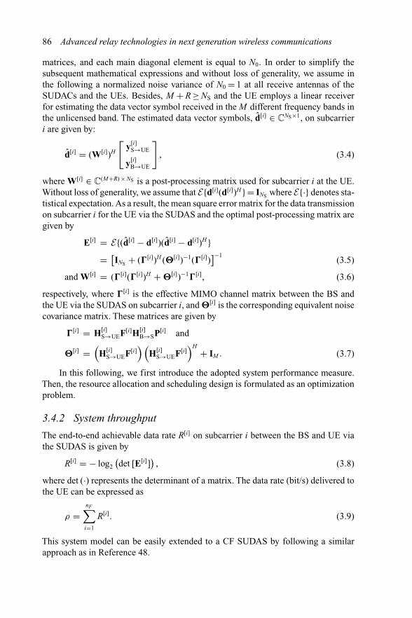
matrices, and each main diagonal element is equal to N0. In order to simplify thesubsequent mathematical expressions and without loss of generality, we assume inthe following a normalized noise variance of N0 = 1 at all receive antennas of theSUDACs and the UEs. Besides, M + R ≥ NS and the UE employs a linear receiverfor estimating the data vector symbol received in the M different frequency bands inthe unlicensed band. The estimated data vector symbols, d̂[i] ∈ C
NS×1, on subcarrieri are given by:
d̂[i] = (W[i])H
[y[i]
S→UE
y[i]B→UE
]
, (3.4)
where W[i] ∈ C(M+R) × NS is a post-processing matrix used for subcarrier i at the UE.
Without loss of generality, we assume that E{d[i](d[i])H } = INS where E{·} denotes sta-tistical expectation. As a result, the mean square error matrix for the data transmissionon subcarrier i for the UE via the SUDAS and the optimal post-processing matrix aregiven by
E[i] = E{(d̂[i] − d[i])(d̂[i] − d[i])H }= [
INS + (�[i])H (�[i])−1(�[i])]−1
(3.5)
and W[i] = (�[i](�[i])H + �[i])−1�[i], (3.6)
respectively, where �[i] is the effective MIMO channel matrix between the BS andthe UE via the SUDAS on subcarrier i, and �[i] is the corresponding equivalent noisecovariance matrix. These matrices are given by
�[i] = H[i]S→UEF[i]H[i]
B→SP[i] and
�[i] =(
H[i]S→UEF[i]
) (H[i]
S→UEF[i])H + IM . (3.7)
In this following, we first introduce the adopted system performance measure.Then, the resource allocation and scheduling design is formulated as an optimizationproblem.
3.4.2 System throughput
The end-to-end achievable data rate R[i] on subcarrier i between the BS and UE viathe SUDAS is given by
R[i] = − log2
(det [E[i]]
), (3.8)
where det (·) represents the determinant of a matrix. The data rate (bit/s) delivered tothe UE can be expressed as
ρ =nF∑
i=1
R[i]. (3.9)
This system model can be easily extended to a CF SUDAS by following a similarapproach as in Reference 48.

SUDAS: mmWave relaying for 5G outdoor-to-indoor communications 87
Table 3.1 System parameters
Mobile band carrier center frequency 800 MHz
mmWave band carrier center frequency 60 GHzUseful signal bandwidth 200 MHzChannel model for mobile band to/from BS Winner+ outdoor-to-indoorChannel model for mmWave links IEEE 802.11ad
LOS living room scenarioBS antenna height 25 mHeight of SUDAC and UE 1.5 mDistance BS ↔ SUDAC 96 mDistance BS ↔ UE 100 mDistance SUDAC ↔ UE 4 mAntenna (mobile band) gain of SUDAC and UE 0 dBiAntenna (mmWave band) gain of SUDAC and UE 3 dBi (semi-isotropic)Noise figure of SUDAC and UE 8 dBMaximum transmit power per SUDAC in mmWave 13 dBm
3.5 Numerical results
We focus on a single-cell downlink communication scenario where an LTE-type BSequipped with 16 antennas serves a UE via a SUDAS with 14 SUDACs. The UEis equipped with two mobile band antennas and one mmWave band antenna, whileeach SUDAC has one mobile band antenna and one mmWave antenna. The importantsimulation parameters are summarized in Table 3.1. Carrier aggregation is performedsuch that a total bandwidth of 200 MHz is available in the mobile band for downlinkcommunication. We assume that the downlink channels from the BS to the SUDASare mutually statistically independent for any pair of BS antennas. Also, in orderto reveal the potential of SUDAS, we assume perfect synchronization and channelestimation. Furthermore, we adopt equal power allocation at both the BS and eachSUDAC. The system achievable data rate is computed by (3.9).
3.5.1 Average system throughput versus transmit power
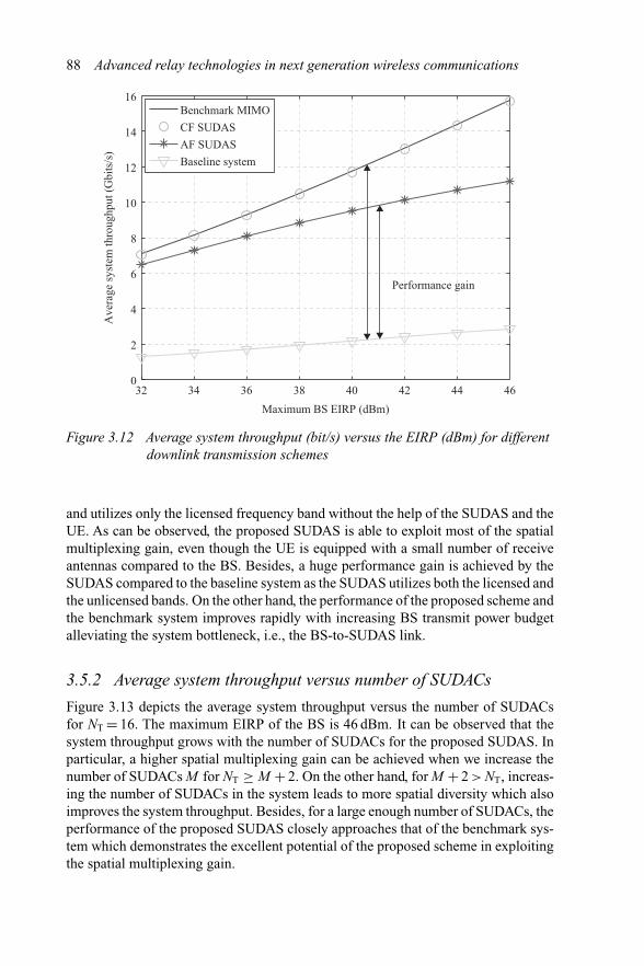
Figure 3.12 shows the average system throughput versus the equivalent isotropicallyradiated power (EIRP) (dBm) for different downlink transmission schemes. As can beseen, both SUDAS with AF and CF relaying realize an extraordinarily high data ratebringing 10 Gbit/s to the indoor UEs over a distance of 100 m. For comparison, we alsoshow the system performance of a benchmark MIMO system and a baseline system.For the benchmark MIMO system, we assume that the UE is equipped with 16 receiveantennas without the help of the SUDAS, and optimal resource allocation is performedto maximize the system throughput. In other words, the average system throughputof the benchmark system serves as a performance upper bound for the proposedSUDAS. As for the baseline system, the BS performs optimal resource allocation
88 Advanced relay technologies in next generation wireless communications
32 34 36 38 40 42 44 460
2
4
6
8
10
12
14
16
Maximum BS EIRP (dBm)
Ave
rage
syst
em th
roug
hput
(Gbi
ts/s
)
Performance gain
Benchmark MIMOCF SUDASAF SUDASBaseline system
Figure 3.12 Average system throughput (bit/s) versus the EIRP (dBm) for differentdownlink transmission schemes
and utilizes only the licensed frequency band without the help of the SUDAS and theUE. As can be observed, the proposed SUDAS is able to exploit most of the spatialmultiplexing gain, even though the UE is equipped with a small number of receiveantennas compared to the BS. Besides, a huge performance gain is achieved by theSUDAS compared to the baseline system as the SUDAS utilizes both the licensed andthe unlicensed bands. On the other hand, the performance of the proposed scheme andthe benchmark system improves rapidly with increasing BS transmit power budgetalleviating the system bottleneck, i.e., the BS-to-SUDAS link.
3.5.2 Average system throughput versus number of SUDACs
Figure 3.13 depicts the average system throughput versus the number of SUDACsfor NT = 16. The maximum EIRP of the BS is 46 dBm. It can be observed that thesystem throughput grows with the number of SUDACs for the proposed SUDAS. Inparticular, a higher spatial multiplexing gain can be achieved when we increase thenumber of SUDACs M for NT ≥ M + 2. On the other hand, for M + 2 > NT, increas-ing the number of SUDACs in the system leads to more spatial diversity which alsoimproves the system throughput. Besides, for a large enough number of SUDACs, theperformance of the proposed SUDAS closely approaches that of the benchmark sys-tem which demonstrates the excellent potential of the proposed scheme in exploitingthe spatial multiplexing gain.

SUDAS: mmWave relaying for 5G outdoor-to-indoor communications 89
8 9 10 11 12 13 14 15 162
4
6
8
10
12
14
16
18
Number of SUDACs
Ave
rage
syst
em th
roug
hput
(Gbi
ts/s
)
Performance gain
Benchmark MIMOCF SUDASAF SUDASBaseline system
Figure 3.13 Average system throughput (Mbits/s) versus the number of SUDACsfor a maximum EIRP at the BS of 46 dBm for different downlinktransmission schemes
3.6 SUDAS – challenges
Although the proposed SUDAS has a strong potential to reach the data rate require-ments set by 5G, there are many questions and challenges that need to be addressedindividually. In this section, we discuss some research challenges arising in thepractical implementation of SUDAS for outdoor-to-indoor communication.
3.6.1 Keyhole effect
The SUDAS performance requires suitable channel conditions for creating a VMIMOsystem from an outdoor BS to an indoor SUDAC. However, it is known that theso-called keyhole effect can lead to performance degradation of the VMIMO channelbecause of the following three phenomena [49, 50]:
1. Spatial keyholes2. Diffraction-induced keyholes3. Modal keyholes
Fortunately, Almers et al. [51] show that there is only a negligible spatial keyhole effectif an opening of at least 30 cm × 30 cm exists in a metal wall. As a result, wheneverthe SUDAS is used in an environment that meets this condition (e.g., rooms withtypical window sizes), we can safely assume that spatial keyholes will not affect the

90 Advanced relay technologies in next generation wireless communications
mmWave band
payload s/c payload
A B
f fB A
Mobile bands (UHF)
Figure 3.14 Spectrum occupation in mmWave band and mobile bands (UHF):aggregation of multiple mobile carriers in the mmWave band
performance of a SUDAS. On the other hand, Chizhik et al. [50] relate diffraction-induced keyholes to outdoor scenarios and also propose a solution for the placementof the BS antennas to counter this effect. Besides, modal keyholes will occur whenthe waves propagate along hallway-like structures. This could be the case in an indoorscenario or a street canyon. The authors in Reference 49 proposed a relaying systemfor MIMO which could mitigate such effects. Therefore, it appears that SUDASwill not severely suffer from the above three described keyhole effects. However,further channel measurements and studies should be conducted to verify the channelconditions needed for the successful implementation of SUDAS.
3.6.2 Carrier aggregation
As carrier aggregation will probably be used in 5G, a SUDAS has to allow the relayingof several carriers simultaneously. A simple solution is to assign one SUDAC toone mobile carrier frequency only and to assign further carriers to other SUDACs.Alternatively, several independent RF chains could be bundled in a single SUDACdevice. Similarly, several mobile downlink channels could be aggregated inside aSUDAC. For instance, a “double” AF SUDAC could bundle two carriers that areseparated in frequency in the mobile bands to adjacent channels in the mmWaveband, see Figure 3.14.
3.6.3 Resource allocation for multiple MNOs
As stated before, a SUDAS should allow any UE to connect to the network of theirassociated MNOs. Thereby, one SUDAS can host different UEs associated with dif-ferent MNOs concurrently. This must be taken into account by the resource allocation.The resources allocated to a SUDAS are not only the time, frequency, code, and spaceoccupied in the mmWave band but also the relaying (i.e., hardware) resources repre-sented by the pool of SUDACs in the indoor environment. A fair resource allocationmust ensure that the available data rates are assigned to each UE according to the qual-ity of service requirements of its services, the number of carriers that can be relayed,and to the UE’s and SUDAC’s capabilities to support certain carrier frequencies,carrier spacings, bandwidths, channel switching times, transmit powers, etc. More-over, policies defined by the MNO concerning the data rates granted to certain UEsor services should be taken into account. Besides, the resource allocation must ensurethat interference between multiple mmWave links or other users of the mmWave bands(such as IEEE 802.11ad) is avoided.
SUDAS: mmWave relaying for 5G outdoor-to-indoor communications 91
Position 2LOS to 1, 2, 3
Position 1LOS to 1, 2
2
3
1
Position 3LOS to 1, 3
Trajectory of UESUDACUE Wall
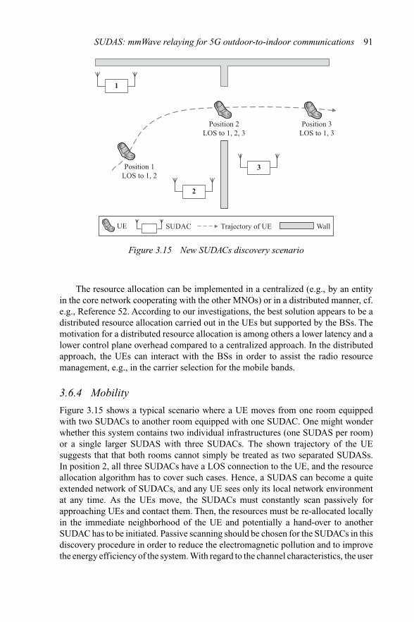
Figure 3.15 New SUDACs discovery scenario
The resource allocation can be implemented in a centralized (e.g., by an entityin the core network cooperating with the other MNOs) or in a distributed manner, cf.e.g., Reference 52. According to our investigations, the best solution appears to be adistributed resource allocation carried out in the UEs but supported by the BSs. Themotivation for a distributed resource allocation is among others a lower latency and alower control plane overhead compared to a centralized approach. In the distributedapproach, the UEs can interact with the BSs in order to assist the radio resourcemanagement, e.g., in the carrier selection for the mobile bands.
3.6.4 Mobility
Figure 3.15 shows a typical scenario where a UE moves from one room equippedwith two SUDACs to another room equipped with one SUDAC. One might wonderwhether this system contains two individual infrastructures (one SUDAS per room)or a single larger SUDAS with three SUDACs. The shown trajectory of the UEsuggests that that both rooms cannot simply be treated as two separated SUDASs.In position 2, all three SUDACs have a LOS connection to the UE, and the resourceallocation algorithm has to cover such cases. Hence, a SUDAS can become a quiteextended network of SUDACs, and any UE sees only its local network environmentat any time. As the UEs move, the SUDACs must constantly scan passively forapproaching UEs and contact them. Then, the resources must be re-allocated locallyin the immediate neighborhood of the UE and potentially a hand-over to anotherSUDAC has to be initiated. Passive scanning should be chosen for the SUDACs in thisdiscovery procedure in order to reduce the electromagnetic pollution and to improvethe energy efficiency of the system. With regard to the channel characteristics, the user
92 Advanced relay technologies in next generation wireless communications
mobility causes relatively high Doppler shifts due to the very high carrier frequencyin the mmWave band. For instance, moving the UE at 10 km/h when turning aroundwill cause an instantaneous Doppler shift of 550 Hz.
3.6.5 Synchronization and channel estimation
The aforementioned momentary Doppler shift is high but it is still within the rangesupported by LTE, where the maximum tolerable Doppler frequency is 840 Hz. There-fore, for an AF SUDAC, the UEs or the BS are in principle able to compensate thechannel variations over the complete end-to-end link. However, the time-derivativeof the Doppler shift can be very high in the mmWave band and might exceed thecapabilities of the BS or the UEs. Moreover, indoor SUDACs are fortunately notmobile but installed in a more or less fixed location. Therefore, the channel betweenthe BS and the SUDACs in the mobile bands is frequency selective but quite static,while the channel between the SUDACs and the UEs in the mmWave band is time-variant but affected only by relatively flat fading (over up to 20 MHz bandwidth).Sophisticated AF SUDACs could exploit these properties and compensate the chan-nel variations over the mmWave link, e.g., remove the Doppler shift if required. Thesituation changes when it comes to the usage of SUDACs in trains, buses, and cars.Now, also the channel between the BS and the SUDAC is time-variant with possiblyhigh Doppler shift. This would add to the Doppler shift originating from the mmWavelink, e.g., when the user moves in a train. Hence, the compensation of the Dopplershift by the SUDAC as described above becomes indispensable in the case of AFrelaying. On the other hand, for fixed indoor SUDACs installed in an industrial envi-ronment such as a factory building, the delay spread may be much longer than theaforementioned 10–20 ns [47]. The longer delays are due to the larger spaces lackingabsorbing walls and including metallic reflectors. For such scenarios, the mmWavechannel can be quite frequency selective, and an AF SUDAC is unable to compensatethese effects. Instead, equalization must be performed at the BS or the UEs. Addi-tionally, the phase noise mask of a mmWave carrier is significantly worse than thattypically encountered in mobile UHF bands. An AF SUDAC could compensate partof this phase noise by utilizing the pilots embedded in the s/c channel. Without suchcompensation, it is questionable whether a BS or a UE would be able to estimate andcompensate the phase noise.
3.6.6 Power consumption
With regard to power consumption, according to Reference 53, the total power con-sumption of a transceiver chip (that processes similar data rates in receive and transmitdirections) appears to be governed largely by the power dissipated by the power ampli-fier. In contrast, the power required for the digital baseband processing (e.g., forwarderror correction decoding) is probably a minor part compared to the consumption inthe power amplifier. As a result, AF and CF SUDASs are expected to consume similaramounts of power, and the choice of the SUDAS relaying protocol may depend moreon the hardware complexity.

SUDAS: mmWave relaying for 5G outdoor-to-indoor communications 93
3.7 Conclusions
In this chapter, we have proposed a novel SUDAS with the objective of achieving the10 Gbit/s data rate goal set by 5G for indoor UEs. The proposed SUDAS exploits thebenefits of the licensed and unlicensed frequency bands simultaneously. In particular,it translates the spatial multiplexing in the licensed bands into frequency multiplex-ing in the unlicensed bands for boosting the end-to-end data rate via VMIMO. Itis expected that the proposed SUDAS can further enhance the system performancewhen advanced resource allocation technique is employed. Besides, we have alsodiscussed some potential application scenarios where deployment of SUDAS appearsto be beneficial. Also, we have investigated different potential realizations of SUDASand the corresponding implementation challenges. It is expected that the proposedSUDAS is able to bridge the gap between the current technology and the high datarate requirement of the next generation communication systems.
Acknowledgements
This work was supported in part by the AvH Professorship Program of the Alexandervon Humboldt Foundation.
References
[1] D. Tse and P. Viswanath, Fundamentals of Wireless Communication, 1st ed.Cambridge University Press, United Kingdom, 2005.
[2] A. Goldsmith, Wireless Communications. Cambridge University Press, UnitedKingdom, 2005.
[3] V. K. N. Lau and Y. K. Kwok, Channel Adaptation Technologies and CrossLayer Design for Wireless Systems with Multiple Antennas – Theory andApplications, 1st ed. Wiley John Proakis Telecom Series, New York, 2005.
[4] M. Dohler, “Virtual Antenna Arrays,” Ph.D. dissertation, Kings CollegeLondon, University of London, Nov. 2003.
[5] D. W. K. Ng and R. Schober, “Cross-Layer Scheduling Design for CooperativeWireless Two-Way Relay Networks,” Cooperative Cellular Wireless Networks,Cambridge University Press, United Kingdom, p. 259, 2011.
[6] D. W. K. Ng, E. S. Lo, and R. Schober, “Energy-Efficient Resource Alloca-tion in Multi-Cell OFDMA Systems with Limited Backhaul Capacity,” IEEETrans. Wireless Commun., vol. 11, pp. 3618–3631, Oct. 2012.
[7] D. Ng and R. Schober, “Dynamic Resource Allocation in OFDMA Systemswith Full-Duplex and Hybrid Relaying,” in Proc. IEEE Intern. Commun.Conf., Jun. 2011, pp. 1–6.
[8] T. Riihonen, S. Werner, and R. Wichman, “Hybrid Full-Duplex/Half-DuplexRelaying with Transmit Power Adaptation,” IEEE Trans. Wireless Commun.,vol. 10, pp. 3074–3085, Sep. 2011.

94 Advanced relay technologies in next generation wireless communications
[9] D. W. K. Ng, E. S. Lo, and R. Schober, “Dynamic Resource Allocationin MIMO-OFDMA Systems with Full-Duplex and Hybrid Relaying,” IEEETrans. Commun., vol. 60, pp. 1291–1304, May 2012.
[10] I. Hammerstrom and A. Wittneben, “Power Allocation Schemes for Amplify-and-Forward MIMO-OFDM Relay Links,” IEEE Trans. Wireless Commun.,vol. 6, pp. 2798–2802, Aug. 2007.
[11] N. Zlatanov, R. Schober, and P. Popovski, “Buffer-Aided Relaying with Adap-tive Link Selection,” IEEE J. Select. Areas Commun., vol. 31, pp. 1530–1542,Aug. 2013.
[12] N. Zlatanov and R. Schober, “Buffer-Aided Relaying with Adaptive LinkSelection-Fixed and Mixed Rate Transmission,” IEEE Trans. Inf. Theory,vol. 59, pp. 2816–2840, May 2013.
[13] Y. Liu, M.Tao, B. Li, and H. Shen, “Optimization Framework and Graph-BasedApproach for Relay-Assisted Bidirectional OFDMA Cellular Networks,”IEEE Trans. Wireless Commun., vol. 9, no. 11, pp. 3490–3500, Nov. 2010.
[14] Y. Liu and M. Tao, “Optimal Channel and Relay Assignment in OFDM-BasedMulti-Relay Multi-Pair Two-Way Communication Networks,” IEEE Trans.Commun., vol. 60, no. 2, pp. 317–321, Feb. 2012.
[15] Y. Liu, J. Mo, and M. Tao, “QoS-Aware Transmission Policies forOFDM Bidirectional Decode-and-Forward Relaying,” IEEE Trans. WirelessCommun., vol. 12, pp. 2206–2216, May 2013.
[16] E. Calvo, J. Vidal, and J. R. Fonollosa, “Optimal Resource Allocation in Relay-Assisted Cellular Networks with Partial CSI,” IEEE Trans. Signal Process.,vol. 57, pp. 2809–2823, Jul. 2009.
[17] Y.Yu andY. Hua, “Power Allocation for a MIMO Relay System with Multiple-Antenna Users,” IEEE Trans. Signal Process., vol. 58, pp. 2823–2835,May 2010.
[18] C. Wang, H. Wang, D. Ng, X. Xia, and C. Liu, “Joint Beamforming and PowerAllocation for Secrecy in Peer-to-Peer Relay Networks,” IEEE Trans. WirelessCommun., vol. 14, no. 6, pp. 3280–3293, June 2015.
[19] C. Li, X. Wang, L. Yang, and W.-P. Zhu, “A Joint Source and Relay PowerAllocation Scheme for a Class of MIMO Relay Systems,” IEEE Trans. SignalProcess., vol. 57, pp. 4852–4860, Dec. 2009.
[20] I. Ahmed, A. Ikhlef, D. Ng, and R. Schober, “Power Allocation for a HybridEnergy Harvesting Relay System with Imperfect Channel and Energy StateInformation,” in Proc. IEEE Wireless Commun. Netw. Conf., Apr. 2014,pp. 990–995.
[21] Y. Fu, L. Yang, and W.-P. Zhu, “A Nearly Optimal Amplify-and-ForwardRelaying Scheme for Two-Hop MIMO Multi-Relay Networks,” IEEECommun. Lett., vol. 14, pp. 229–231, Mar. 2010.
[22] D. Ng and R. Schober, “Resource Allocation for Secure OFDMA Decode-and-Forward Relay Networks,” in 12th Canadian Workshop Inf. Theory (CWIT),May 2011, pp. 202–205.
[23] D. Ng and R. Schober, “Resource Allocation and Scheduling in Multi-CellOFDMA Decode-and-Forward Relaying Networks,” in Proc. IEEE GlobalTelecommun. Conf., Dec. 2010, pp. 1–6.
SUDAS: mmWave relaying for 5G outdoor-to-indoor communications 95
[24] I. Ahmed, A. Ikhlef, D. Ng, and R. Schober, “Optimal Resource Allocationfor Energy Harvesting Two-Way Relay Systems with Channel Uncertainty,”in IEEE Global Conf. Signal Inf. Process., Dec. 2013, pp. 345–348.
[25] D. Ng and R. Schober, “Cross-Layer Scheduling Design for OFDMA Two-WayAmplify-and-Forward Relay Networks,” in Proc. IEEEWireless Commun.Netw. Conf., Apr. 2010, pp. 1–6.
[26] D. Ng and R. Schober, “Cross-Layer Scheduling for OFDMA Amplify-and-Forward Relay Networks,” in Proc. IEEEVeh. Techn. Conf., Sep. 2009, pp. 1–5.
[27] X. Chen, L. Lei, H. Zhang, and C. Yuen, “Large-Scale MIMO RelayingTechniques for Physical Layer Security: AF or DF?” IEEE Trans. WirelessCommun., vol. PP, no. 99, 2015.
[28] J. Zeng and H. Minn, “A Novel OFDMA Ranging Method ExploitingMultiuser Diversity,” IEEE Trans. Commun., vol. 58, pp. 945–955, Mar. 2010.
[29] P. Chan and R. Cheng, “Capacity Maximization for Zero-Forcing MIMO-OFDMA Downlink Systems with Multiuser Diversity,” IEEE Trans. WirelessCommun., vol. 6, pp. 1880–1889, May 2007.
[30] D. Ng, E. Lo, and R. Schober, “Energy-Efficient Resource Allocation inOFDMA Systems with Hybrid Energy Harvesting Base Station,” IEEE Trans.Wireless Commun., vol. 12, pp. 3412–3427, Jul. 2013.
[31] H. Bogucka and A. Conti, “Degrees of Freedom for Energy Savings in Prac-tical Adaptive Wireless Systems,” IEEE Commun. Mag., vol. 49, pp. 38–45,Jun. 2011.
[32] A. Chowdhery, W. Yu, and J. M. Cioffi, “Cooperative Wireless MulticellOFDMA Network with Backhaul Capacity Constraints,” in Proc. IEEEIntern. Commun. Conf., Jun. 2011, pp. 1–6.
[33] T. Marzetta, “Noncooperative Cellular Wireless with Unlimited Num-bers of Base Station Antennas,” IEEE Trans. Wireless Commun., vol. 9,pp. 3590–3600, Nov. 2010.
[34] Y. Wu, R. Schober, D. W. K. Ng, C. Xiao, and G. Caire, “Secure MassiveMIMO Transmission in the Presence of an Active Eavesdropper,” in Proc.IEEE Intern. Commun. Conf., Jun. 2015.
[35] D. W. K. Ng, E. Lo, and R. Schober, “Energy-Efficient Resource Allocationin OFDMA Systems with Large Numbers of Base Station Antennas,” IEEETrans. Wireless Commun., vol. 11, pp. 3292–3304, Sep. 2012.
[36] K. Kumar, G. Caire, and A. Moustakas, “Asymptotic Performance of LinearReceivers in MIMO Fading Channels,” IEEE Trans. Inf. Theory, vol. 55,pp. 4398–4418, Oct. 2009.
[37] Z. Qi, LTE Throughput Leader Nokia Sets World Record with SK Tele-com of Close to 4 Gbps Using TDD-FDD Carrier Aggregation, 2014.[Online] Available: http://nsn.com/news-events/press-room/press-releases/lte-throughput-leader-nokia-sets-world-record-with-sk-telecom-of-close-to-4-gbps-using-tdd
[38] L. D. Heyn, A. Grooten, C. Holden, et al., Cost Model – CountryAnalysis Report (CAR) for Germany, 2013. [Online] Available: http://www.ftthcouncil.eu/documents/Reports/2013/Cost_Model_CAR_Germany_August2013.pdf

96 Advanced relay technologies in next generation wireless communications
[39] R. Pabst, B. Walke, D. Schultz, et al., “Relay-Based Deployment Conceptsfor Wireless and Mobile Broadband Radio,” IEEE Commun. Mag., vol. 42,pp. 80–89, Sep 2004.
[40] D. Ng, E. Lo, and R. Schober, “Energy-Efficient Resource Allocation inMulti-Cell OFDMA Systems with Limited Backhaul Capacity,” in Proc.IEEE Wireless Commun. Netw. Conf., Apr. 2012, pp. 1146–1151.
[41] D. W. K. Ng and R. Schober, “Secure and Green SWIPT in DistributedAntenna Networks with Limited Backhaul Capacity,” IEEE Trans. WirelessCommun., vol. 14, no. 9, pp. 5082–5097, Sep. 2015.
[42] D. Ng and R. Schober, “Resource Allocation for Coordinated MultipointNetworks with Wireless Information and Power Transfer,” in Proc. IEEEGlobal Telecommun. Conf., Dec. 2014, pp. 4281–4287.
[43] T. Rappaport, S. Sun, R. Mayzus, et al., “Millimeter Wave Mobile Communi-cations for 5G Cellular: It Will Work!” IEEEAccess, vol. 1, pp. 335–349, 2013.
[44] M. Breiling, D. W. K. Ng, C. Rohde, F. Burkhardt, and R. Schober, “ResourceAllocation for Outdoor-to-Indoor Multicarrier Transmission with SharedUE-Side DistributedAntenna Systems,” in Proc. IEEEVeh. Techn. Conf., 2015.
[45] H. Andersson, M. Björn, S. Carson, et al., Ericsson Mobility Report,2013. [Online] Available: http://ec.europa.eu/digital-agenda/en/news/2014-report-implementation-eu-regulatory-framework-electronic-communications
[46] H. Ding, D. B. da Costa, and J. Ge, “A Centralized Role Selection Scheme forTwo-User Amplify-and-Forward Relaying Systems,” in Proc. IEEE WirelessCommun. Netw. Conf., Apr. 2013, pp. 3476–3481.
[47] T. Rappaport, J. Murdock, and F. Gutierrez, “State of the Art in 60-GHzIntegrated Circuits and Systems for Wireless Communications,” Proc. IEEE,vol. 99, pp. 1390–1436, Aug. 2011.
[48] J. Jiang, M. Dianati, M. Imran, and Y. Chen, “Energy Efficiency and OptimalPower Allocation in Virtual-MIMO Systems,” in Proc. IEEE Veh. Techn.Conf., Sep. 2012, pp. 1–6.
[49] O. Souihli and T. Ohtsuki, “Cooperative Diversity Can Mitigate KeyholeEffects in Wireless MIMO Systems,” in Proc. IEEE Global Telecommun.Conf., Nov. 2009, pp. 1–6.
[50] D. Chizhik, G. Foschini, M. Gans, and R. Valenzuela, “Keyholes, Correla-tions, and Capacities of Multielement Transmit and Receive Antennas,” IEEETrans. Wireless Commun., vol. 1, pp. 361–368, Apr. 2002.
[51] P. Almers, F. Tufvesson, and A. Molisch, “Keyhole Effect in MIMO WirelessChannels: Measurements and Theory,” IEEE Trans. Wireless Commun., vol. 5,pp. 3596–3604, Dec. 2006.
[52] R. A. Ramirez, E. Altman, J. S. Thompson, and R. M. Ramos, “A StableMarriage Framework for Distributed Virtual MIMO Coalition Formation,” inProc. IEEE Personal, Indoor and Mobile Radio Commun. Symp., Sep. 2013,pp. 2707–2712.
[53] A. Jensen, M. Lauridsen, P. Mogensen, T. Sorensen, and P. Jensen, “LTEUE Power Consumption Model: For System Level Energy and PerformanceOptimization,” in Proc. IEEE Veh. Techn. Conf., Sep. 2012, pp. 1–5.