chapter 3 - physical characteristicscaa.gov.rw/img/pdf/chapter_3_physical_characteristics.pdfmanual...
TRANSCRIPT
Manual of Aerodrome Standards RCAA-MAN-AGA001
Chapter 3. Physical Characteristics
09 May 2011 3-1
CHAPTER 3 - PHYSICAL CHARACTERISTICS
3.1 Introduction
3.1.1 This chapter contains specifications related to the physical characteristics
required of aerodrome runway, taxiway, apron and related facilities.
3.2 Physical requirements of aerodrome facilities
3.2.1 Runways
3.2.1.1 Number and orientation of runways
Introductory Note — Many factors affect the determination of the orientation, siting
and number of runways. One important factor is the usability factor, as determined by
the wind distribution, which is specified hereunder. Another important factor is the
alignment of the runway to facilitate the provision of approaches conforming to the
approach surface specifications of Chapter 4 of this Manual.
In ICAO Annex 14 Vol. I, Attachment A, Section 1, information is given concerning
these and other factors. When a new instrument runway is being located, particular
attention needs to be given to areas over which aeroplanes will be required to fly when
following instrument approach and missed approach procedures, so as to ensure that
obstacles in these areas or other factors will not restrict the operation of the aeroplanes
for which the runway is intended.
3.2.1.2The number and orientation of runways at an aerodrome should be such that the
usability factor of the aerodrome is not less than 95 per cent for the aeroplanes that the
aerodrome is intended to serve.
3.2.1.3 Choice of maximum permissible cross-wind components
In the application of paragraph 3.2.1.1 above, it should be assumed that landing or
take-off of aeroplanes is, in normal circumstances, precluded when the cross-wind
component exceeds:
– 37 km/h (20 kt) in the case of aeroplanes whose reference field length is
1 500 m or over, except that when poor runway braking action owing to an
insufficient longitudinal coefficient of friction is experienced with some
frequency, a cross-wind component not exceeding 24 km/h (13 kt) should be
assumed;
– 24 km/h (13 kt) in the case of aeroplanes whose reference field length is
1 200 m or up to but not including 1 500 m; and
– 19 km/h (10 kt) in the case of aeroplanes whose reference field length is less
than 1 200 m.
Manual of Aerodrome Standards RCAA-MAN-AGA001
Chapter 3. Physical Characteristics
09 May 2011 3-2
Note: — In ICAO Annex 14 Vol. I, Attachment A, Section 1, guidance is given on
factors affecting the calculation of the estimate of the usability factor and allowances
which may have to be made to take account of the effect of unusual circumstances.
3.2.1.4 Data to be used
The selection of data to be used for the calculation of the usability factor should be
based on reliable wind distribution statistics that extend over as long a period as
possible, preferably of not less than five years. The observations used should be made
at least eight times daily and spaced at equal intervals of time.
Note — These winds are mean winds. Reference to the need for some
allowance for gusty conditions is made in ICAO Annex 14 Vol. I, Attachment A,
Section 1.
Location of threshold
3.2.1.5 A threshold should normally be located at the extremity of a runway unless
operational considerations justify the choice of another location.
Note — Guidance on the siting of the threshold is given in ICAO Annex
14 Vol. I, Attachment A, Section 10.
3.2.1.6 When it is necessary to displace a threshold, either permanently or temporarily,
from its normal location, account should be taken of the various factors which may
have a bearing on the location of the threshold. Where this displacement is due to an
unserviceable runway condition, a cleared and graded area of at least 60 m in length
should be available between the unserviceable area and the displaced threshold.
Additional distance should also be provided to meet the requirements of the runway
end safety area as appropriate.
Note — Guidance on factors which may be considered in the determination of the
location of a displaced threshold is given in ICAO Annex 14 Vol. I, Attachment A,
Section 10.
Actual length of runways
3.2.1.7 Primary runway
Except as provided in paragraph 3.2.1.8 of this Manual, the actual runway length to be
provided for a primary runway should be adequate to meet the operational
requirements of the aeroplanes for which the runway is intended and should be not less
than the longest length determined by applying the corrections for local conditions to
the operations and performance characteristics of the relevant aeroplanes.
Note 1 — This specification does not necessarily mean providing for operations by the
critical aeroplane at its maximum mass.
Manual of Aerodrome Standards RCAA-MAN-AGA001
Chapter 3. Physical Characteristics
09 May 2011 3-3
Note 2 — Both take-off and landing requirements need to be considered when
determining the length of runway to be provided and the need for operations to be
conducted in both directions of the runway.
Note 3 — Local conditions that may need to be considered include elevation,
temperature, runway slope, humidity and the runway surface characteristics.
Note 4 — When performance data on aeroplanes for which the runway is intended are
not known, guidance on the determination of the actual length of a primary runway by
application of general correction factors is given in the ICAO Aerodrome Design
Manual, Part 1.
3.2.1.8 Secondary runway
The length of a secondary runway should be determined similarly to primary runways
except that it needs only to be adequate for those aeroplanes which require to use that
secondary runway in addition to the other runway or runways in order to obtain a
usability factor of at least 95 per cent.
3.2.1.9 Runways with stop-ways or clearways
Where a runway is associated with a stop-way or clearway, an actual runway length
less than that resulting from application of paragraphs 3.2.1.7 or 3.2.1.8, as
appropriate, may be considered satisfactory, but in such a case any combination of
runway, stop-way and clearway provided should permit compliance with the
operational requirements for take-off and landing of the aeroplanes the runway is
intended to serve.
Note — Guidance on use of stop-ways and clearways is given in ICAO
Annex 14 Vol. I, Attachment A, Section 2.
Width of runways
3.2.1.10 The width of a runway shall not be less than the appropriate dimension
specified in the following tabulation:
Code letter
Code number A B C D E F
1a 18 m 18 m 23 m - - -
2a 23 m 23 m 30 m - - -
3 30 m 30 m 30 m 45 m - -
4 - - 45 m 45 m 45 m 60 m
a. The width of a precision approach runway should be not less than 30 m where the
code number is 1 or 2.
Note 1 — The combinations of code numbers and letters for which widths are specified
have been developed for typical aeroplane characteristics.
Manual of Aerodrome Standards RCAA-MAN-AGA001
Chapter 3. Physical Characteristics
09 May 2011 3-4
Note 2 — Factors affecting runway width are given in the ICAO Aerodrome Design
Manual, Part 1.
Minimum distance between parallel runways
3.2.1.11 Where parallel non-instrument runways are intended for simultaneous use, the
minimum distance between their centre lines shall be:
– 210 m where the higher code number is 3 or 4;
– 150 m where the higher code number is 2; and
– 120 m where the higher code number is 1.
Note — Procedures for wake turbulence categorization of aircraft and wake
turbulence separation minima are contained in the Procedures for Air Navigation
Services — Rules of the Air and Air Traffic Services (PANS-RAC), Doc 4444, Part V,
Section 16.
3.2.1.12 Where parallel instrument runways are intended for simultaneous use subject
to conditions specified in the PANS-RAC (Doc 4444) and the PANS-OPS (Doc 8168),
Volume I, the minimum distance between their centre lines shall be:
– 1 035 m for independent parallel approaches;
– 915 m for dependent parallel approaches;
– 760 m for independent parallel departures;
– 760 m for segregated parallel operations;
except that:
a) for segregated parallel operations the specified minimum distance:
1) may be decreased by 30 m for each 150 m that the arrival runway is
staggered toward the arriving aircraft, to a minimum of 300 m; and
2) should be increased by 30 m for each 150 m that the arrival runway is
staggered away from the arriving aircraft;
b) for independent parallel approaches, combinations of minimum distances and
associated conditions other than those specified in the PANS-RAC (Doc 4444)
may be applied when it is determined that such combinations would not
adversely affect the safety of aircraft operations.
Note — Procedures and facilities requirements for simultaneous operations on parallel or
near-parallel instrument runways are contained in the PANS-RAC (Doc 4444), Part IV and
the PANS-OPS (Doc 8168), Volume I, Part VII and Volume II, Parts II and III and relevant
guidance is contained in the ICAO Manual of Simultaneous Operations on Parallel or Near-
Parallel Instrument Runways (Doc 9643).
Slopes on runways
3.2.1.13 Longitudinal slopes
Manual of Aerodrome Standards RCAA-MAN-AGA001
Chapter 3. Physical Characteristics
09 May 2011 3-5
The slope computed by dividing the difference between the maximum and minimum
elevation along the runway centre line by the runway length shall not exceed:
a) 1 per cent where the code number is 3 or 4; and
b) 2 per cent where the code number is 1 or 2.
3.2.1.14 An operator shall not allow any portion of a runway to exceed the longitudinal
slopes stipulated as follows:
a) 1.25 per cent where the code number is 4, except that for the first and last
quarter of the length of the runway the longitudinal slope should not exceed 0.8
per cent;
b) 1.5 per cent where the code number is 3, except that for the first and last
quarter of the length of a precision approach runway category II or III the
longitudinal slope should not exceed 0.8 percent; and
c) 2 per cent where the code number is 1 or 2.
3.2.1.15 Longitudinal slope changes
Where slope changes cannot be avoided, a slope change between two consecutive
slopes shall not exceed:
a) 1.5 per cent where the code number is 3 or 4; and
b) 2 per cent where the code number is 1 or 2.
Note — Guidance on slope changes before a runway is given in ICAO
Annex 14 Vol. I, Attachment A, Section 4.
3.2.1.16 The transition from one slope to another shall be accomplished by a curved
surface with a rate of change not exceeding:
a) 0.1 per cent per 30 m (minimum radius of curvature of 30 000 m) where the
code number is 4;
b) 0.2 per cent per 30 m (minimum radius of curvature of 15 000 m) where the
code number is 3; and
c) 0.4 per cent per 30 m (minimum radius of curvature of 7 500 m) where the
code number is 1 or 2.
3.2.1.17 Sight distance
a) Where slope changes cannot be avoided, they shall be such that there will be an
unobstructed line of sight from;
Manual of Aerodrome Standards RCAA-MAN-AGA001
Chapter 3. Physical Characteristics
09 May 2011 3-6
b) any point 3 m above a runway to all other points 3 m above the runway within
a distance of at least half the length of the runway where the code letter is C, D,
E or F;
c) any point 2 m above a runway to all other points 2 m above the runway within
a distance of at least half the length of the runway where the code letter is B;
and
d) any point 1.5 m above a runway to all other points 1.5 m above the runway
within a distance of at least half the length of the runway where the code letter
is A.
Note — Consideration will have to be given to providing an unobstructed line of sight
over the entire length of a single runway where a full-length parallel taxiway is not
available. Where an aerodrome has intersecting runways, additional criteria on the
line of sight of the intersection area would need to be considered for operational
safety. See the ICAO Aerodrome Design Manual, Part 1.
3.2.1.18 Distance between slope changes
Undulations or appreciable changes in slopes located close together along a runway
shall be avoided. The distance between the points of intersection of two successive
curves shall not be less than:
a) the sum of the absolute numerical values of the corresponding slope changes
multiplied by the appropriate value as follows:
– 30 000 m where the code number is 4;
– 15 000 m where the code number is 3; and
– 5 000 m where the code number is 1 or 2; or
b) 45 m;
whichever is greater.
Note — Guidance on implementing this specification is given in ICAO
Annex 14 Vol. I, Attachment A, Section 4.
3.2.1.19 Transverse slopes
To promote the most rapid drainage of water, the runway surface should, if
practicable, be cambered except where a single cross fall from high to low in the
direction of the wind most frequently associated with rain would ensure rapid
drainage. The transverse slope should ideally be:
– 1.5 per cent when the code letter is C, D, E or F;
– 2 per cent when the code letter is A or B;
but in any event should not exceed 1.5 per cent or 2 per cent, as applicable, nor be less
than 1 per cent except at runway or taxiway intersections where flatter slopes may be
Manual of Aerodrome Standards RCAA-MAN-AGA001
Chapter 3. Physical Characteristics
09 May 2011 3-7
necessary. For a cambered surface the transverse slope on each side of the centre line
should be symmetrical.
Note — On wet runways with cross-wind conditions the problem of aquaplaning from
poor drainage is apt to be accentuated. In ICAO Annex 14 Vol. I, Attachment A,
Section 7, information is given concerning this problem and other relevant factors.
3.2.1.20 The transverse slope shall be substantially the same throughout the length of a
runway except at an intersection with another runway or a taxiway where an even
transition shall be provided taking account of the need for adequate drainage.
Note — Guidance on transverse slope is given in the ICAO Aerodrome
Design Manual, Part 3.
Strength of runways
3.2.1.21 A runway shall be capable of withstanding the traffic of aeroplanes the
runway is intended to serve.
Surface of runways
3.2.1.22 The surface of a runway shall be constructed without irregularities that would
result in loss in friction characteristics or otherwise adversely affect the take-off or
landing of an aeroplane.
Note 1 — Surface irregularities may adversely affect the take-off or landing of an
aeroplane by causing excessive bouncing, pitching, vibration, or other difficulties in
the control of an aeroplane.
Note 2 — Guidance on design tolerances and other information is given in ICAO
Annex 14 Vol. I, Attachment A, Section 5. Additional guidance is included in the ICAO
Aerodrome Design Manual, Part 3.
3.2.1.23 The surface of a paved runway shall be so constructed as to provide good
friction characteristics when the runway is wet.
3.2.1.24 Measurements of the friction characteristics of a new or resurfaced runway
shall be made with a continuous friction measuring device using self-wetting features
in order to assure that the design objectives with respect to its friction characteristics
have been achieved.
Note — Guidance on friction characteristics of new runway surfaces is given in ICAO
Annex 14 Vol. I, Attachment A, Section 7. Additional guidance is included in the ICAO
Airport Services Manual, Part 2.
3.2.1.25 The average surface texture depth of a new surface should be not less than 1.0
mm.
Note 1 — This normally requires some form of special surface treatment.

Manual of Aerodrome Standards RCAA-MAN-AGA001
Chapter 3. Physical Characteristics
09 May 2011 3-8
Note 2 — Guidance on methods used to measure surface texture is given in the ICAO
Airport Services Manual, Part 2.
3.2.1.26 When the surface is grooved or scored, the grooves or scorings should be
either perpendicular to the runway centre line or parallel to non-perpendicular
transverse joints, where applicable.
Note — Guidance on methods for improving the runway surface texture is given in the
ICAO Aerodrome Design Manual, Part3.
3.2.2 Runway shoulders
Note — Guidance on characteristics and treatment of runway shoulders is given in
ICAO Annex 14 Vol. I, Attachment A, Section 8, and in the ICAO Aerodrome Design
Manual, Part 1.
3.2.2.1 Runway shoulders shall be provided for a runway where the code letter is D or
E, and the runway width is less than 60 m.
3.2.2.2 Runway shoulders shall be provided for a runway where the code letter is F.
Width of runway shoulders
3.2.2.3 The runway shoulders should extend symmetrically on each side of the runway
so that the overall width of the runway and its shoulders is not less than:
– 60 m where the code letter is D or E; and
– 75 m where the code letter is F.
Slopes on runway shoulders
3.2.2.4 The surface of the shoulder that abuts the runway shall be flush with the
surface of the runway and its transverse slope shall not exceed 2.5 per cent.
Strength of runway shoulders
3.2.2.5 A runway shoulder shall be prepared or constructed so as to be capable, in the
event of an aeroplane running off the runway, of supporting the aeroplane without
inducing structural damage to the aeroplane and of supporting ground vehicles which
may operate on the shoulder.
3.2.3 Runway turn pads
3.2.3.1 Where the end of a runway is not served by a taxiway or a taxiway turnaround
and where the code letter is D, E or F, a runway turn pad shall be provided to facilitate
180 degree turn of aeroplanes. (See figure 3-1 Annex 14 Volume 1 Para 3.3.1)
Manual of Aerodrome Standards RCAA-MAN-AGA001
Chapter 3. Physical Characteristics
09 May 2011 3-9
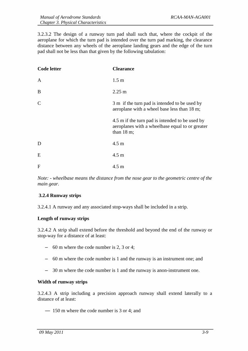
3.2.3.2 The design of a runway turn pad shall such that, where the cockpit of the
aeroplane for which the turn pad is intended over the turn pad marking, the clearance
distance between any wheels of the aeroplane landing gears and the edge of the turn
pad shall not be less than that given by the following tabulation:
Code letter Clearance
A 1.5 m
B 2.25 m
C 3 m if the turn pad is intended to be used by
aeroplane with a wheel base less than 18 m;
4.5 m if the turn pad is intended to be used by
aeroplanes with a wheelbase equal to or greater
than 18 m;
D 4.5 m
E 4.5 m
F 4.5 m
Note: - wheelbase means the distance from the nose gear to the geometric centre of the
main gear.
3.2.4 Runway strips
3.2.4.1 A runway and any associated stop-ways shall be included in a strip.
Length of runway strips
3.2.4.2 A strip shall extend before the threshold and beyond the end of the runway or
stop-way for a distance of at least:
– 60 m where the code number is 2, 3 or 4;
– 60 m where the code number is 1 and the runway is an instrument one; and
– 30 m where the code number is 1 and the runway is anon-instrument one.
Width of runway strips
3.2.4.3 A strip including a precision approach runway shall extend laterally to a
distance of at least:
— 150 m where the code number is 3 or 4; and
Manual of Aerodrome Standards RCAA-MAN-AGA001
Chapter 3. Physical Characteristics
09 May 2011 3-10
— 75 m where the code number is 1 or 2; on each side of the centre line of the
runway and its extended centre line throughout the length of the strip.
3.2.4.4 A strip including a non-precision approach runway shall extend laterally to a
distance of at least:
— 150 m where the code number is 3 or 4; and
— 75 m where the code number is 1 or 2;
on each side of the centre line of the runway and its extended centre line throughout
the length of the strip.
3.2.4.5 A strip including a non-instrument runway shall extend on each side of the
centre line of the runway and its extended centre line throughout the length of the strip,
to a distance of at least:
— 75 m where the code number is 3 or 4;
— 40 m where the code number is 2; and
— 30 m where the code number is 1.
Objects on runway strips
Note — See paragraph 9.10 of this Manual for information regarding siting and
construction of equipment and installations on runway strips.
3.2.4.6 An object situated on a runway strip, which may endanger aeroplanes shall be
regarded as an obstacle and shall be removed.
3.2.4.7 No fixed object, other than visual aids required for air navigation purposes and
satisfying the relevant frangibility requirement in para 9.10 of this Manual, shall be
permitted on a runway strip:
a) within 77.5 m of the runway centre line of a precision approach runway
category I or II where the code number is 4 and the code letter is F; or
b) within 60 m of the runway centre line of a precision approach runway category
I or II where the code number is 3 or 4; or
c) within 45 m of the runway centre line of a precision approach runway category
I where the code number is 1 or 2. No mobile object shall be permitted on this
part of the runway strip during the use of the runway for landing or take-off.
Grading of runway strips
3.2.4.8 That portion of a strip of an instrument runway within a distance of at least:
— 75 m where the code number is 3 or 4; and
— 40 m where the code number is 1 or 2;
Manual of Aerodrome Standards RCAA-MAN-AGA001
Chapter 3. Physical Characteristics
09 May 2011 3-11
from the centre line of the runway and its extended centre line shall provide a graded
area for aeroplanes, which the runway is intended to serve in the event of an aeroplane
running off the runway.
Note — Guidance on grading of a greater area of a strip including a precision
approach runway where the code number is 3 or 4 is given in ICAO Annex 14 Vol. I,
Attachment A, Section 8.
3.2.4.9 That portion of a strip of a non-instrument runway within a distance of at least:
— 75 m where the code number is 3 or 4;
— 40 m where the code number is 2; and
— 30 m where the code number is 1;
from the centre line of the runway and its extended centre line shall provide a graded
area for aeroplanes, which the run-way is intended to serve in the event of an
aeroplane running off the runway.
3.2.4.10 The surface of that portion of a strip that abuts a runway, shoulder or stop-
way shall be flush with the surface of the runway, shoulder or stop-way.
3.2.4.11 That portion of a strip to at least 30 m before a threshold shall be prepared
against blast erosion in order to protect a landing aeroplane from the danger of an
exposed edge.
Slopes on runway strips
3.2.4.12 Longitudinal slopes
A longitudinal slope along that portion of a strip to be graded shall not exceed:
— 1.5 per cent where the code number is 4;
— 1.75 per cent where the code number is 3; and
— 2 per cent where the code number is 1 or 2.
3.2.4.13 Longitudinal slope changes
Slope changes on that portion of a strip to be graded shall be as gradual as practicable
and abrupt changes or sudden reversals of slopes avoided.
3.2.4.14 Transverse slopes
Transverse slopes on that portion of a strip to be graded shall be adequate to prevent
the accumulation of water on the surface but should not exceed:
— 2.5 per cent where the code number is 3 or 4; and
— 3 per cent where the code number is 1 or 2;
Manual of Aerodrome Standards RCAA-MAN-AGA001
Chapter 3. Physical Characteristics
09 May 2011 3-12
except that to facilitate drainage the slope for the first 3 m outward from the runway,
shoulder or stop-way edge shall be negative as measured in the direction away from
the runway and may be as great as 5 per cent.
3.2.4.15 The transverse slopes of any portion of a strip beyond that to be graded shall
not exceed an upward slope of 5 per cent as measured in the direction away from the
runway.
Strength of runway strips
3.2.4.16 That portion of a strip of an instrument runway within a distance of at least:
— 75 m where the code number is 3 or 4; and
— 40 m where the code number is 1 or 2
from the centre line of the runway and its extended centre line shall be so prepared or
constructed as to minimize hazards arising from differences in load bearing capacity
to aeroplanes, which the runway is intended to serve in the event of an aeroplane
running off the runway.
Note — Guidance on preparation of runway strips is given in the ICAO
Aerodrome Design Manual, Part 1.
3.2.4.17 That portion of a strip containing a non-instrument runway within a distance
of at least:
— 75 m where the code number is 3 or 4;
— 40 m where the code number is 2; and
— 30 m where the code number is 1;
from the centre line of the runway and its extended centre line shall be so prepared or
constructed as to minimize hazards arising from differences in load bearing capacity to
aeroplanes, which the runway is intended to serve in the event of an aeroplane running
off the runway.
Manual of Aerodrome Standards RCAA-MAN-AGA001
Chapter 3. Physical Characteristics
09 May 2011 3-13
3.2.5 Runway end safety areas
General
3.2.5.1 A runway end safety area shall be provided at each end of a runway strip
where:
— the code number is 3 or 4; and
— the code number is 1 or 2 and the runway is an instrument one.
Note — Guidance on runway end safety areas is given in ICAO Annex 14 Vol. I,
Attachment A, Section 9.
Dimensions of runway end safety areas
3.2.5.2 A runway end safety area shall extend from the end of a runway strip to
a distance of at least 90 m.
3.2.5.3 A runway end safety area should, as far as practicable, extend from the end of a
runway strip to a distance of at least:
— 240 m where the code number is 3 or 4; and
— 120 m where the code number is 1 or 2.
3.2.5.4 The width of a runway end safety area shall be at least twice that of the
associated runway.
3.2.5.5 The width of a runway end safety area should, wherever practicable, be equal
to that of the graded portion of the associated runway strip.
Objects on runway end safety areas
Note — See paragraph 9.10 of this Manual for information regarding siting and
construction of equipment and installations on runway end safety areas.
3.2.5.6 An object situated on a runway end safety area, which may endanger
aeroplanes shall be regarded as an obstacle and shall be removed.
Clearing and grading of runway end safety areas
3.2.5.7 A runway end safety area shall provide a cleared and graded area for
aeroplanes which the runway is intended to serve in the event of an aeroplane
undershooting or overrunning the runway.
Note — The surface of the ground in the runway end safety area does not need to be
prepared to the same quality as the runway strip. See,, paragraph 3.2.5.11 of this
Manual.
Manual of Aerodrome Standards RCAA-MAN-AGA001
Chapter 3. Physical Characteristics
09 May 2011 3-14
Slopes on runway end safety areas
3.2.5.8 General
The slopes of a runway end safety area shall be such that no part of the runway end
safety area penetrates the approach or take-off climb surface.
3.2.5.9 Longitudinal slopes
The longitudinal slopes of a runway end safety area shall not exceed a downward slope
of 5 per cent. Longitudinal slope changes shall be as gradual as practicable and abrupt
changes or sudden reversals of slopes avoided.
3.2.5.10 Transverse slopes
The transverse slopes of a runway end safety area shall not exceed an upward or
downward slope of 5 per cent. Transitions between differing slopes should be as
gradual as practicable.
Strength of runway end safety areas
3.2.5.11 A runway end safety area shall be so prepared or constructed as to
reduce the risk of damage to an aeroplane undershooting or overrunning the runway,
enhance aeroplane deceleration and facilitate the movement of rescue and fire fighting
vehicles as required in paragraphs 9.3.26 to 9.3.28 of this Manual.
Note — Guidance on strength of a runway end safety area is given in the ICAO
Aerodrome Design Manual, Part 1.
3.2.6 Clearways
Note — The inclusion of detailed specifications for clearways in this section is not
intended to imply that a clearway has to be provided. ICAO Annex 14, Vol. I,
Attachment A, Section 2 provides information on the use of clearways.
Location of clearways
3.2.6.1 The origin of a clearway shall be at the end of the take-off run available.
Length of clearways
3.2.6.2 The length of a clearway shall not exceed half the length of the take-off
run available.
Width of clearways
3.2.6.3 A clearway should extend laterally to a distance of at least 75 m on each side of
the extended centre line of the runway.
Manual of Aerodrome Standards RCAA-MAN-AGA001
Chapter 3. Physical Characteristics
09 May 2011 3-15
Slopes on clearways
3.2.6.4 The ground in a clearway shall not project above a plane having an upward
slope of 1.25 per cent, the lower limit of this plane being a horizontal line which:
a) is perpendicular to the vertical plane containing the runway centre line; and
b) passes through a point located on the runway centre line at the end of the take-
off run available.
Note — Because of transverse or longitudinal slopes on a runway, shoulder or strip, in
certain cases the lower limit of the clearway plane specified above may be below the
corresponding elevation of the runway, shoulder or strip. It is not intended that these
surfaces be graded to conform with the lower limit of the clearway plane nor is it
intended that terrain or objects which are above the clearway plane beyond the end of
the strip but below the level of the strip be removed unless it is considered they may
endanger aeroplanes.
3.2.6.5 Abrupt upward changes in slope shall be avoided when the slope on the ground
in a clearway is relatively small or when the mean slope is upward. In such situations,
in that portion of the clearway within a distance of 22.5 m or half the runway width
whichever is greater on each side of the extended centre line, the slopes, slope changes
and the transition from runway to clearway shall conform with those of the runway
with which the clearway is associated.
Objects on clearways
Note — See paragraph 9.10 of this Manual for information regarding siting and
construction of equipment and installations on clearways.
3.2.6.6 An object situated on a clear-way, which may endanger aeroplanes in the air
shall be regarded as an obstacle and shall be removed.
Manual of Aerodrome Standards RCAA-MAN-AGA001
Chapter 3. Physical Characteristics
09 May 2011 3-16
3.2.7 Stop-ways
Note — The inclusion of detailed specifications for stop-ways in this section is not
intended to imply that a stop-way has to be provided. ICAO Annex 14, Vol. I,
Attachment A, Section 2 provides information on the use of stop-ways.
Width of stop-ways
3.2.7.1 A stop-way shall have the same width as the runway with which it is
associated.
Slopes on stop-ways
3.2.7.2 Slopes and changes in slope on a stop-way, and the transition from a runway to
a stop-way, shall comply with the specifications of paragraphs 3.2.1.13 to 3.2.1.19 of
this Manual for the runway with which the stop-way is associated except that:
a) the limitation in paragraph 3.2.1.13 of this Manual of a 0.8 per cent slope for
the first and last quarter of the length of a runway need not be applied to the
stop-way; and
b) at the junction of the stop-way and runway and along the stop-way the
maximum rate of slope change may be 0.3per cent per 30 m (minimum radius
of curvature of 10 000 m) for a runway where the code number is 3 or 4.
Strength of stop-ways
3.2.7.3 A stop-way shall be prepared or constructed so as to be capable, in the event of
an abandoned take-off, of supporting the aeroplane which the stop-way is intended to
serve without inducing structural damage to the aeroplane.
Note — ICAO Annex 14 Vol. I, Attachment A, Section 2 presents guidance relative to
the support capability of a stop-way.
Surface of stop-ways
3.2.7.4 The surface of a paved stop-way shall be so constructed as to provide a good
coefficient of friction to be compatible with that of the associated runway when the
stop-way is wet.
3.2.7.5 The friction characteristics of an unpaved stop-way shall not be substantially
less than that of the runway with which the stop-way is associated.
Manual of Aerodrome Standards RCAA-MAN-AGA001
Chapter 3. Physical Characteristics
09 May 2011 3-17
3.2.8 Radio altimeter operating area
General
3.2.8.1 A radio altimeter operating area should be established in the pre-threshold area
of a precision approach runway.
Length of the area
3.2.8.2 A radio altimeter operating area should extend before the threshold for a
distance of at least 300 m.
Width of the area
3.2.8.3 A radio altimeter operating area should extend laterally, on each side of the
extended centre line of the runway, to a distance of 60 m, except that, when special
circumstances so warrant, the distance may be reduced to no less than 30 m if an
aeronautical study indicates that such reduction would not affect the safety of
operations of aircraft.
Longitudinal slope changes
3.2.8.4 On a radio altimeter operating area, slope changes should be avoided or kept to
a minimum. Where slope changes cannot be avoided, the slope changes should be as
gradual as practicable and abrupt changes or sudden reversals of slopes avoided. The
rate of change between two consecutive slopes should not exceed 2per cent per 30 m.
Note — Guidance on radio altimeter operating area is given in ICAO Annex 14 Vol. I,
Attachment A, Section 4.3 and in the ICAO Manual of All-Weather Operations, (Doc
9365), Section 5.2. Guidance on the use of radio altimeter is given in the PANS-OPS,
Volume II, Part III, Chapter 21.
3.2.9 Taxiways
Note — Unless otherwise indicated the requirements in this section are applicable to
all types of taxiways.
General
3.2.9.1 Taxiways shall be provided to permit the safe and expeditious surface
movement of aircraft.
Note — Guidance on layout of taxiways is given in the ICAO Aerodrome Design
Manual, Part 2.
3.2.9.2 Sufficient entrance and exit taxiways for a runway should be provided to
expedite the movement of aeroplanes to and from the runway and provision of rapid
exit taxiways considered when traffic volumes are high.
Note — Where the end of a runway is not served by a taxiway, it maybe necessary to
provide additional pavement at the end of the runway for the turning of aeroplanes.
Manual of Aerodrome Standards RCAA-MAN-AGA001
Chapter 3. Physical Characteristics
09 May 2011 3-18
Such areas may also be useful along the runway to reduce taxiing time and distance
for some aeroplanes.
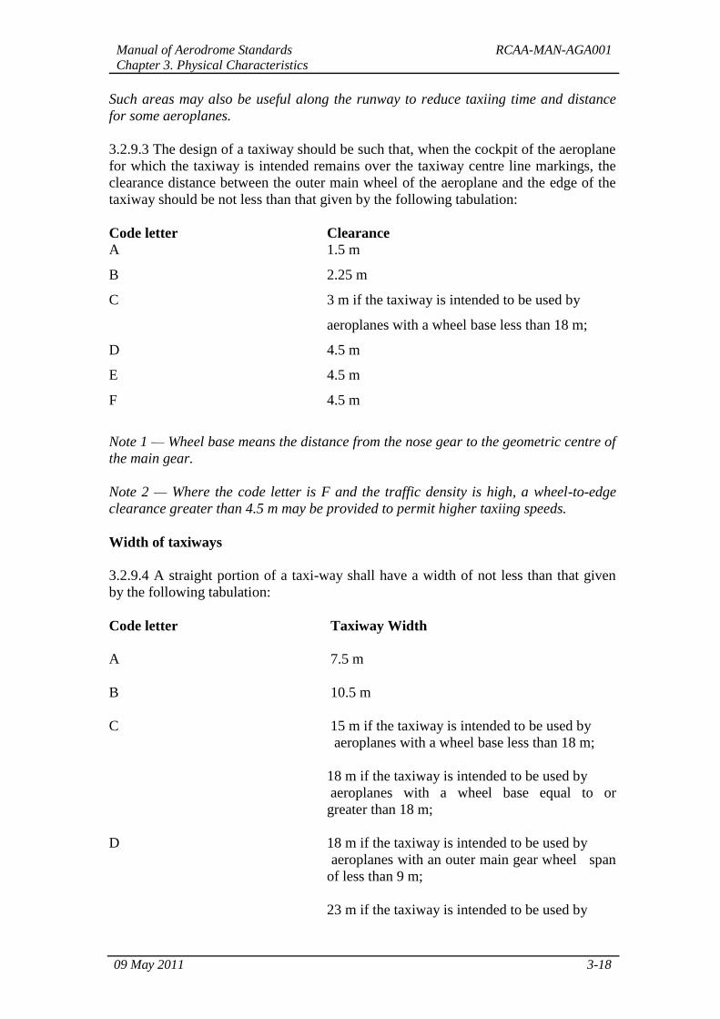
3.2.9.3 The design of a taxiway should be such that, when the cockpit of the aeroplane
for which the taxiway is intended remains over the taxiway centre line markings, the
clearance distance between the outer main wheel of the aeroplane and the edge of the
taxiway should be not less than that given by the following tabulation:
Code letter Clearance
A 1.5 m
B 2.25 m
C 3 m if the taxiway is intended to be used by
aeroplanes with a wheel base less than 18 m;
D 4.5 m
E 4.5 m
F 4.5 m
Note 1 — Wheel base means the distance from the nose gear to the geometric centre of
the main gear.
Note 2 — Where the code letter is F and the traffic density is high, a wheel-to-edge
clearance greater than 4.5 m may be provided to permit higher taxiing speeds.
Width of taxiways
3.2.9.4 A straight portion of a taxi-way shall have a width of not less than that given
by the following tabulation:
Code letter Taxiway Width
A 7.5 m
B 10.5 m
C 15 m if the taxiway is intended to be used by
aeroplanes with a wheel base less than 18 m;
18 m if the taxiway is intended to be used by
aeroplanes with a wheel base equal to or
greater than 18 m;
D 18 m if the taxiway is intended to be used by
aeroplanes with an outer main gear wheel span
of less than 9 m;
23 m if the taxiway is intended to be used by
Manual of Aerodrome Standards RCAA-MAN-AGA001
Chapter 3. Physical Characteristics
09 May 2011 3-19
aeroplanes with an outer main gear wheel span
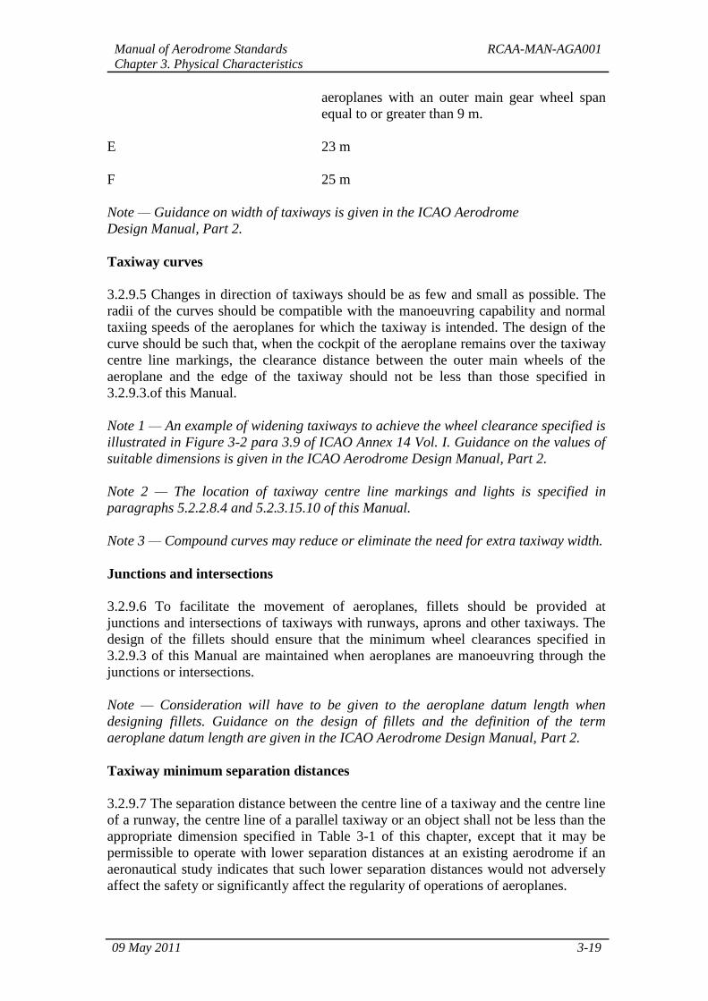
equal to or greater than 9 m.
E 23 m
F 25 m
Note — Guidance on width of taxiways is given in the ICAO Aerodrome
Design Manual, Part 2.
Taxiway curves
3.2.9.5 Changes in direction of taxiways should be as few and small as possible. The
radii of the curves should be compatible with the manoeuvring capability and normal
taxiing speeds of the aeroplanes for which the taxiway is intended. The design of the
curve should be such that, when the cockpit of the aeroplane remains over the taxiway
centre line markings, the clearance distance between the outer main wheels of the
aeroplane and the edge of the taxiway should not be less than those specified in
3.2.9.3.of this Manual.
Note 1 — An example of widening taxiways to achieve the wheel clearance specified is
illustrated in Figure 3-2 para 3.9 of ICAO Annex 14 Vol. I. Guidance on the values of
suitable dimensions is given in the ICAO Aerodrome Design Manual, Part 2.
Note 2 — The location of taxiway centre line markings and lights is specified in
paragraphs 5.2.2.8.4 and 5.2.3.15.10 of this Manual.
Note 3 — Compound curves may reduce or eliminate the need for extra taxiway width.
Junctions and intersections
3.2.9.6 To facilitate the movement of aeroplanes, fillets should be provided at
junctions and intersections of taxiways with runways, aprons and other taxiways. The
design of the fillets should ensure that the minimum wheel clearances specified in
3.2.9.3 of this Manual are maintained when aeroplanes are manoeuvring through the
junctions or intersections.
Note — Consideration will have to be given to the aeroplane datum length when
designing fillets. Guidance on the design of fillets and the definition of the term
aeroplane datum length are given in the ICAO Aerodrome Design Manual, Part 2.
Taxiway minimum separation distances
3.2.9.7 The separation distance between the centre line of a taxiway and the centre line
of a runway, the centre line of a parallel taxiway or an object shall not be less than the
appropriate dimension specified in Table 3-1 of this chapter, except that it may be
permissible to operate with lower separation distances at an existing aerodrome if an
aeronautical study indicates that such lower separation distances would not adversely
affect the safety or significantly affect the regularity of operations of aeroplanes.
Manual of Aerodrome Standards RCAA-MAN-AGA001
Chapter 3. Physical Characteristics
09 May 2011 3-20
Note 1 — Guidance on factors, which may be considered in the aeronautical study, is
given in the ICAO Aerodrome Design Manual, Part 2.
Note 2 — ILS and MLS installations may also influence the location of taxiways due to
interferences to ILS and MLS signals by a taxiing or stopped aircraft. Information on
critical and sensitive areas surrounding ILS and MLS installations is contained in
ICAO Annex 10, Volume I, Attachments C and G (respectively) to Part I.
Note 3 — The separation distances of Table 3-1, column 10, do not necessarily
provide the capability of making a normal turn from one taxiway to another parallel
taxiway. Guidance for this condition is given in the ICAO Aerodrome Design Manual,
Part 2.
Note 4 — The separation distance between the centre line of an aircraft stand taxi lane
and an object shown in Table 3-1, column 12, may need to be increased when jet
exhaust wake velocity may cause hazardous conditions for ground servicing.
Manual of Aerodrome Standards RCAA-MAN-AGA001
Chapter 3. Physical Characteristics
09 May 2011 3-21
Table 3-1 – Taxiway minimum separation distances
Code
letter
Distance between taxiway centreline
and runway centre line (metres)
Taxiway
centre
line to
taxiway
centre
line
(metres)
Taxiway
other
than
aircraft
stand
taxilane
centre
line to
object
(metres)
Aircraft
stand
taxilane
centre
line to
object
(metres)
Instrument runways
Code number
Non-instrument runways
Code number
1 2 3 4 1 2 3 4
(1) (2) (3) (4) (5) (6) (7) (8) (9) (10) (11) (12)
A 82.5 82.5 - - 37.5 47.5 - - 23.75 16.25 12
B 87 87 - - 42 52 - - 33.5 21.5 16.5
C - - 168 - - - 93 - 44 26 24.5
D - - 176 176 - - 101 101 66.5 40.5 36
E - - - 182.5 - - - 107.5 80 47.5 42.5
F - - - 190 - - - 115 97.5 57.5 50.5
Note 1 – The separation distances shown in columns (2) to (9) represent ordinary combinations of
runways and taxiways. The basis for development of these distances is given in the ICAO
Aerodrome Design Manual, Part2.
Note 2 – The distances in columns (2) to (9) do not guarantee sufficient clearance behind a holding
aeroplane to permit the passing of another aeroplane on a parallel taxiway. See ICAO Aerodrome
Design Manual, Part 2.
Slopes on taxiways
3.2.9.8 Longitudinal slopes
The longitudinal slope of a taxiway shall not exceed:
— 1.5 per cent where the code letter is C, D, E or F; and
— 3 per cent where the code letter is A or B.
3.2.9.9 Longitudinal slope changes
Where slope changes on a taxiway cannot be avoided, the transition from one slope to
another slope shall be accomplished by a curved surface with a rate of change not
exceeding:
— 1 per cent per 30 m (minimum radius of curvature of 3 000 m) where the code
letter is C, D, E or F; and
— 1 per cent per 25 m (minimum radius of curvature of 2 500 m) where the code
letter is A or B.
3.2.9.10 Sight distance
Manual of Aerodrome Standards RCAA-MAN-AGA001
Chapter 3. Physical Characteristics
09 May 2011 3-22
Where a change in slope on a taxiway cannot be avoided, the change shall be such
that, from any point:
a) 3 m above the taxiway, it will be possible to see the whole surface of
the taxiway for a distance of at least 300 m from that point, where the
code letter is C, D, E or F;
b) 2 m above the taxiway, it will be possible to see the whole surface of
the taxiway for a distance of at least 200 m from that point, where the
code letter is B; and
c) 1.5 m above the taxiway, it will be possible to see the whole surface of
the taxiway for a distance of at least 150 m from that point, where the
code
d) letter is A.
3.2.9.11 Transverse slopes
The transverse slopes of a taxiway shall be sufficient to prevent the accumulation of
water on the surface of the taxiway but should not exceed:
— 1.5 per cent where the code letter is C, D, E or F; and
— 2 per cent where the code letter is A or B.
Note — See paragraph 3.2.13.4 of this Manual regarding transverse slopes on an
aircraft stand taxilane.
Strength of taxiways
3.2.9.12 The strength of a taxiway shall be at least equal to that of the runway it
serves, due consideration being given to the fact that a taxiway will be subjected to a
greater density of traffic and, as a result of slow moving and stationary aeroplanes, to
higher stresses than the runway it serves.
Note — Guidance on the relation of the strength of taxiways to the strength of runways
is given in the ICAO Aerodrome Design Manual, Part 3.
Manual of Aerodrome Standards RCAA-MAN-AGA001
Chapter 3. Physical Characteristics
09 May 2011 3-23
Surface of taxiways
3.2.9.13 The surface of a taxiway should not have irregularities that cause damage to
aeroplane structures.
3.2.9.14 The surface of a paved taxiway should be so constructed as to provide good
friction characteristics when the taxiway is wet.
Rapid exit taxiways
Note — The following specifications detail requirements particular to rapid exit
taxiways. See Figure 3-3 of ICAO Annex 14 Vol. I. General requirements for taxiways
also apply to this type of taxiway. Guidance on the provision, location and design of
rapid exit taxiways is included in the ICAO Aerodrome Design Manual, Part 2.
3.2.9.15 A rapid exit taxiway shall be designed with a radius of turn-off curve of at
least:
— 550 m where the code number is 3 or 4; and
— 275 m where the code number is 1 or 2;
to enable exit speeds under wet conditions of:
— 93 km/h where the code number is 3 or 4; and
— 65 km/h where the code number is 1 or 2.
Note — The locations of rapid exit taxiways along a runway are based on several
criteria described in the ICAO Aerodrome Design Manual, Part 2, in addition to
different speed criteria.
3.2.9.16 The radius of the fillet on the inside of the curve at a rapid exit taxiway should
be sufficient to provide a widened taxiway throat in order to facilitate early recognition
of the entrance and turn-off onto the taxiway.
3.2.9.17 A rapid exit taxiway should include a straight distance after the turn-off curve
sufficient for an exiting aircraft to come to a full stop clear of any intersecting taxiway.
3.2.9.18 The intersection angle of a rapid exit taxiway with the runway should not be
greater than 45° nor less than 25° and preferably should be 30°.
Manual of Aerodrome Standards RCAA-MAN-AGA001
Chapter 3. Physical Characteristics
09 May 2011 3-24
Taxiways on bridges
3.2.9.19 The width of that portion of a taxiway bridge capable of supporting
aeroplanes, as measured perpendicularly to the taxiway centre line, shall not be less
than the width of the graded area of the strip provided for that taxiway, unless a proven
method of lateral restraint is provided which shall not be hazardous for aeroplanes for
which the taxiway is intended.
3.2.9.20 Access shall be provided to allow rescue and fire fighting vehicles to
intervene in both directions within the specified response time to the largest aeroplane
for which the taxiway bridge is intended.
Note — If aeroplane engines overhang the bridge structure, protection of adjacent
areas below the bridge from engine blast may be required.
3.2.9.21 A bridge shall be constructed on a straight section of the taxiway with a
straight section on both ends of the bridge to facilitate the alignment of aeroplanes
approaching the bridge.
3.2.10 Taxiway shoulders
Note — Guidance on characteristics of taxiway shoulders and on shoulder treatment is
given in the ICAO Aerodrome Design Manual, Part 2.
3.2.10.1 Straight portions of a taxiway where the code letter is C, D, E or F should be
provided with shoulders, which extend symmetrically on each side of the taxiway so
that the overall width of the taxiway and its shoulders on straight portions is not less
than:
— 60 m where the code letter is F;
— 44 m where the code letter is E;
— 38 m where the code letter is D; and
— 25 m where the code letter is C.
On taxiway curves and on junctions or intersections where increased pavement is
provided, the shoulder width should be not less than that on the adjacent straight
portions of the taxiway.
3.2.10.2 When a taxiway is intended to be used by turbine-engined aeroplanes, the
surface of the taxiway shoulder shall be so prepared as to resist erosion and the
ingestion of the surface material by aeroplane engines.
3.2.11 Taxiway strips
Note — Guidance on characteristics of taxiway strips is given in the ICAO Aerodrome
Design Manual, Part 2.
Manual of Aerodrome Standards RCAA-MAN-AGA001
Chapter 3. Physical Characteristics
09 May 2011 3-25
General
3.2.11.1 A taxiway, other than an aircraft stand taxi lane, shall be included in a
strip.
Width of taxiway strips
3.2.11.2 A taxiway strip shall extend symmetrically on each side of the centre line of
the taxiway throughout the length of the taxiway to at least the distance from the centre
line given in Table 3-1, column 11 of this Manual.
Objects on taxiway strips
Note — See paragraph 9.10 of this Manual for information regarding siting and
construction of equipment and installations on taxiway strips.
3.2.11.3 The taxiway strip shall provide an area clear of objects, which may
endanger taxiing aeroplanes.
Note — Consideration will have to be given to the location and design of drains on a
taxiway strip to prevent damage to an aeroplane accidentally running off a taxiway.
Suitably designed drain covers may be required.
Grading of taxiway strips
3.2.11.4 The centre portion of a taxiway strip shall provide a graded area to a
distance from the centre line of the taxiway of at least:
— 11 m where the code letter is A;
— 12.5 m where the code letter is B or C;
— 19 m where the code letter is D;
— 22 m where the code letter is E; and
— 30 m where the code letter is F.
Manual of Aerodrome Standards RCAA-MAN-AGA001
Chapter 3. Physical Characteristics
09 May 2011 3-26
Slopes on taxiway strips
3.2.11.5 The surface of the strip shall be flush at the edge of the taxiway or
shoulder, if provided, and the graded portion shall not have an upward
transverse slope exceeding:
— 2.5 per cent for strips where the code letter is C, D, E or F; and
— 3 per cent for strips of taxiways where the code letter is A or B;
the upward slope being measured with reference to the transverse slope of the adjacent
taxiway surface and not the horizontal. The downward transverse slope shall not
exceed 5 per cent measured with reference to the horizontal.
3.2.11.6 The transverse slopes on any portion of a taxiway strip beyond that to be
graded shall not exceed an upward or downward slope of 5 per cent as measured in the
direction away from the taxiway.
3.2.12 Holding bays, runway-holding positions, intermediate holding positions
and road holding positions
General
3.2.12.1 Holding bay(s) should be provided when the traffic density is medium or
heavy.
3.2.12.2 A runway-holding position or positions shall be established:
a) on the taxiway, at the intersection of a taxiway and a runway; and
b) at an intersection of a runway with another runway when the former runway is
part of a standard taxi-route.
3.2.12.3 A runway-holding position shall be established on a taxiway if the location or
alignment of the taxiway is such that a taxiing aircraft or vehicle can infringe an
obstacle limitation surface or interfere with the operation of radio navigation aids.
3.2.12.4 An intermediate holding position should be established on a taxiway at any
point other than a runway-holding position where it is desirable to define a specific
holding limit.
3.2.12.5 A road-holding position shall be established at an intersection of a road with a
runway.
Location
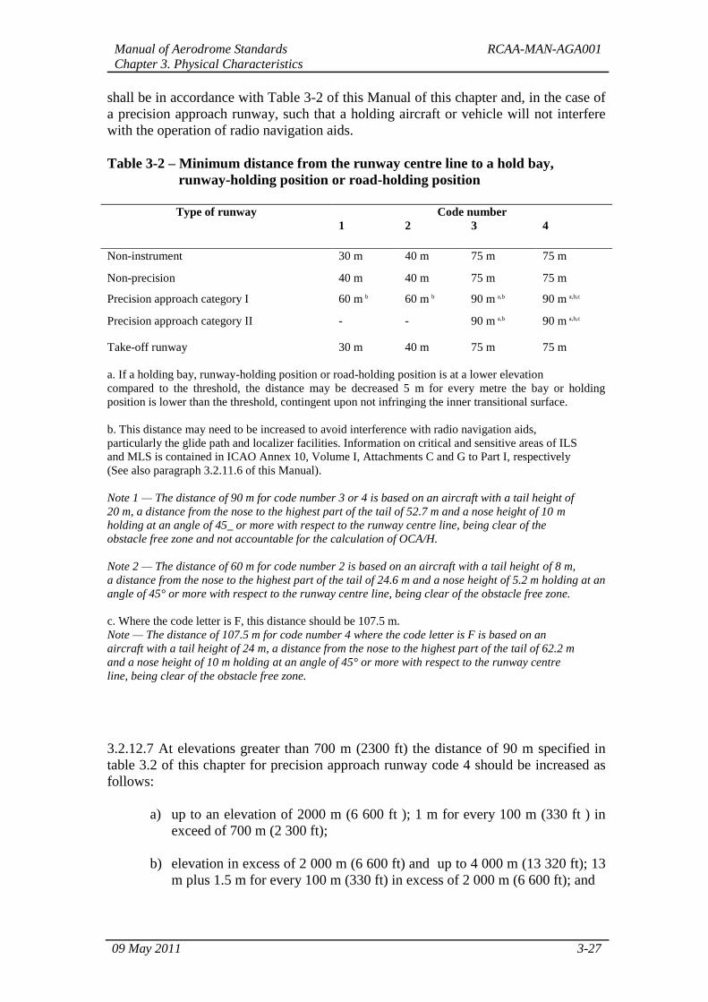
3.2.12.6 The distance between a holding bay, runway-holding position established at a
taxiway/runway intersection or road-holding position and the centre line of a runway
Manual of Aerodrome Standards RCAA-MAN-AGA001
Chapter 3. Physical Characteristics
09 May 2011 3-27
shall be in accordance with Table 3-2 of this Manual of this chapter and, in the case of
a precision approach runway, such that a holding aircraft or vehicle will not interfere
with the operation of radio navigation aids.
Table 3-2 – Minimum distance from the runway centre line to a hold bay,
runway-holding position or road-holding position
Type of runway Code number
1 2 3 4
Non-instrument 30 m 40 m 75 m 75 m
Non-precision 40 m 40 m 75 m 75 m
Precision approach category I 60 m b 60 m b 90 m a,b 90 m a,b,c
Precision approach category II - - 90 m a,b 90 m a,b,c
Take-off runway 30 m 40 m 75 m 75 m
a. If a holding bay, runway-holding position or road-holding position is at a lower elevation
compared to the threshold, the distance may be decreased 5 m for every metre the bay or holding
position is lower than the threshold, contingent upon not infringing the inner transitional surface.
b. This distance may need to be increased to avoid interference with radio navigation aids,
particularly the glide path and localizer facilities. Information on critical and sensitive areas of ILS
and MLS is contained in ICAO Annex 10, Volume I, Attachments C and G to Part I, respectively
(See also paragraph 3.2.11.6 of this Manual).
Note 1 — The distance of 90 m for code number 3 or 4 is based on an aircraft with a tail height of
20 m, a distance from the nose to the highest part of the tail of 52.7 m and a nose height of 10 m
holding at an angle of 45_ or more with respect to the runway centre line, being clear of the
obstacle free zone and not accountable for the calculation of OCA/H.
Note 2 — The distance of 60 m for code number 2 is based on an aircraft with a tail height of 8 m,
a distance from the nose to the highest part of the tail of 24.6 m and a nose height of 5.2 m holding at an
angle of 45° or more with respect to the runway centre line, being clear of the obstacle free zone.
c. Where the code letter is F, this distance should be 107.5 m.
Note — The distance of 107.5 m for code number 4 where the code letter is F is based on an
aircraft with a tail height of 24 m, a distance from the nose to the highest part of the tail of 62.2 m
and a nose height of 10 m holding at an angle of 45° or more with respect to the runway centre
line, being clear of the obstacle free zone.
3.2.12.7 At elevations greater than 700 m (2300 ft) the distance of 90 m specified in
table 3.2 of this chapter for precision approach runway code 4 should be increased as
follows:
a) up to an elevation of 2000 m (6 600 ft ); 1 m for every 100 m (330 ft ) in
exceed of 700 m (2 300 ft);
b) elevation in excess of 2 000 m (6 600 ft) and up to 4 000 m (13 320 ft); 13
m plus 1.5 m for every 100 m (330 ft) in excess of 2 000 m (6 600 ft); and
Manual of Aerodrome Standards RCAA-MAN-AGA001
Chapter 3. Physical Characteristics
09 May 2011 3-28
c) elevation in excess of 4 000 m plus 2 m for every 100 m (330 ft) in excess
of 4 000 m (16 650 ft); 43 m plus 2 m for every 100 m (330 ft) in excess of
4000 m (13 320 ft).
3.2.12.8 If a holding bay, runway-holding position or road-holding position for a
precision approach runway code number 4 is at a greater elevation compared to the
threshold, the distance of 90 m or 107.5 m, as appropriate, specified in Table 3-2 of
this chapter should be further increased 5 m for every metre the bay or position is
higher than the threshold.
3.2.12.9 The location of a runway-holding position established in accordance with
paragraph 3.2.12.3 of this Manual shall be such that a holding aircraft or vehicle will
not infringe the obstacle free zone, approach surface, take-off climb surface or
ILS/MLS critical/ sensitive area or interfere with the operation of radio navigation
aids.
3.2.13 Aprons
General
3.2.13.1 Aprons shall be provided where necessary to permit the on and off loading of
passengers, cargo or mail as well as the servicing of aircraft without interfering with
the aerodrome traffic.
Size of aprons
3.2.13.2 The total apron area should be adequate to permit expeditious handling of the
aerodrome traffic at its maximum anticipated density.
Strength of aprons
3.2.13.3 Each part of an apron shall be capable of withstanding the traffic of the
aircraft it is intended to serve, due consideration being given to the fact that some
portions of the apron will be subjected to a higher density of traffic and, as a result of
slow moving or stationary aircraft, to higher stresses than a runway.
Slopes on aprons
3.2.13.4 Slopes on an apron, including those on an aircraft stand taxi lane, should be
sufficient to prevent accumulation of water on the surface of the apron but should be
kept as level as drainage requirements permit.
3.2.13.5 On an aircraft stand the maximum slope shall not exceed 1 per cent.
Clearance distances on aircraft stands
Manual of Aerodrome Standards RCAA-MAN-AGA001
Chapter 3. Physical Characteristics
09 May 2011 3-29
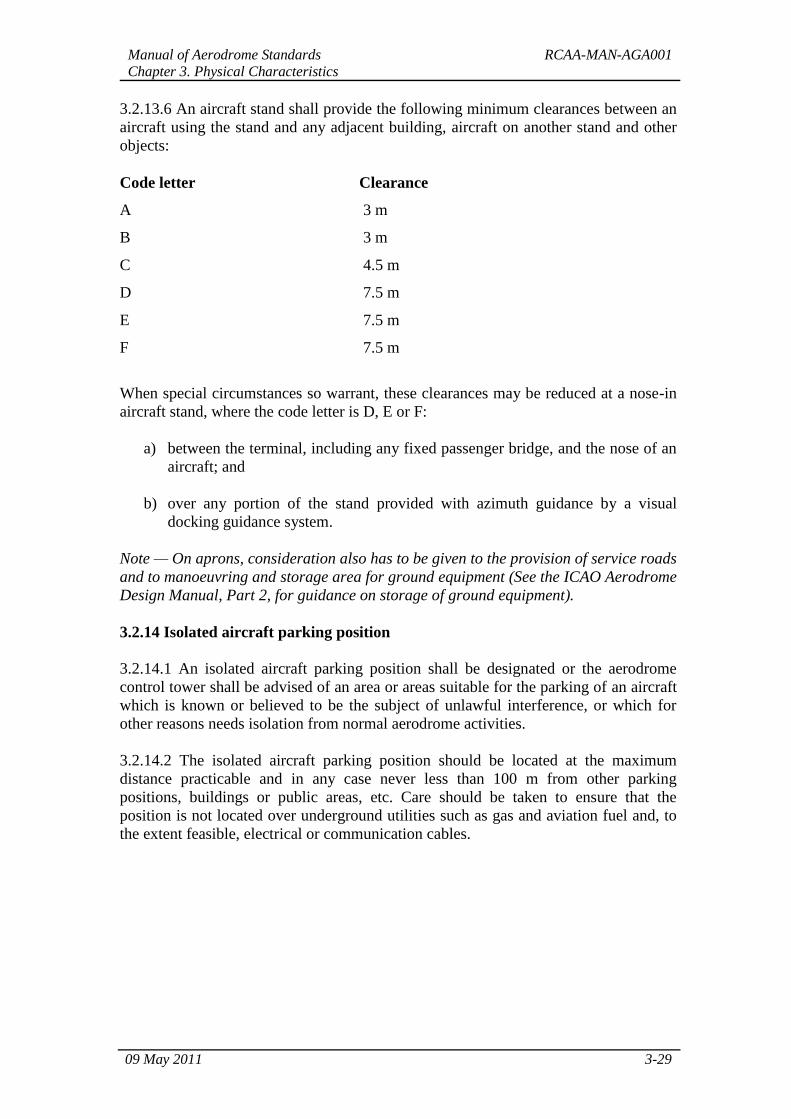
3.2.13.6 An aircraft stand shall provide the following minimum clearances between an
aircraft using the stand and any adjacent building, aircraft on another stand and other
objects:
Code letter Clearance
A 3 m
B 3 m
C 4.5 m
D 7.5 m
E 7.5 m
F 7.5 m
When special circumstances so warrant, these clearances may be reduced at a nose-in
aircraft stand, where the code letter is D, E or F:
a) between the terminal, including any fixed passenger bridge, and the nose of an
aircraft; and
b) over any portion of the stand provided with azimuth guidance by a visual
docking guidance system.
Note — On aprons, consideration also has to be given to the provision of service roads
and to manoeuvring and storage area for ground equipment (See the ICAO Aerodrome
Design Manual, Part 2, for guidance on storage of ground equipment).
3.2.14 Isolated aircraft parking position
3.2.14.1 An isolated aircraft parking position shall be designated or the aerodrome
control tower shall be advised of an area or areas suitable for the parking of an aircraft
which is known or believed to be the subject of unlawful interference, or which for
other reasons needs isolation from normal aerodrome activities.
3.2.14.2 The isolated aircraft parking position should be located at the maximum
distance practicable and in any case never less than 100 m from other parking
positions, buildings or public areas, etc. Care should be taken to ensure that the
position is not located over underground utilities such as gas and aviation fuel and, to
the extent feasible, electrical or communication cables.