chapter 3: iron- and cobalt-containing mcm-41: …
TRANSCRIPT

3 IRON- AND COBALT-CONTAINING MCM-41: Synthesis and Characterization
155
CHAPTER 3: IRON- AND COBALT-CONTAINING MCM-41:
Synthesis and Characterization
The main objectives of this chapter are the preparation and comprehensive characteri-
zation of Fe- and Co-MCM-41 materials. Central to the objectives is the need to synt-
hesize high metal-content MCM-41 during the framework formation step, for
possible use in reactions like Fischer-Tropsch synthesis. A further objective is to
show that the structure of catalysts in the mesoporous environment can produce a
significant impact on metal (Co or Fe) dispersion, reducibility and catalytic performa-
nce in these materials. In particular, these materials will be investigated in later work
as supports for Au catalysts (to be used for the CO oxidation reaction).
3.1. Introduction
Iron-based catalysts [1-3] and cobalt-based catalysts [4-8] have been extensively used
in the Fischer-Tropsch synthesis reaction. The advantage of cobalt-based catalysts
over their iron-based counterparts lies in their high Fischer-Tropsch synthesis (FTS)
activity, C5+ hydrocarbon selectivity, low water-gas shift (WGS) reaction activity and
selectivity and their relatively low cost [9]. They are also used to catalyze hydroform-
ylation and oxidation reactions.
Transition metal oxides are a prominent class of partial oxidation catalysts [10, 11].
However, materials belonging to this class are also active in catalytic total oxidation
processes often carried out on more expensive noble metal-based catalysts [12].
Although the spinel Co3O4 is one of the most active binary oxides for catalytic com-
bustion [13, 14], it is not stable at high temperatures [15]. On the other hand, the pure
sesquioxides with the corundum-type structure, α-Cr2O3 and α-Fe2O3 are active in
combustion catalysis [13, 14].

3 IRON- AND COBALT-CONTAINING MCM-41: Synthesis and Characterization
156
The importance of transition-metal modification of zeolitic materials has been widely
studied by a number of researchers. The advantage of this type of modification is that
the resulting materials can be used as catalysts in both reduction and oxidation react-
ions. In this light, iron oxides supported on silica have been found to exhibit high
catalytic activity in gas-phase and liquid-phase oxidation processes [16, 17, 18].
Among others, Fe/SiO2 catalysts have been applied for the partial oxidation of meth-
ane to formaldehyde [18], and the partial oxidation of hydrogen sulphide to sulphur
[19, 20, 21]. Recently they have been tested in the liquid-phase hydroxylation of
phenol [17] and in styrene epoxidation [22].
In supported metal or metal oxide catalysts, the active phase of an efficient catalyst
mostly exists in the form of a highly dispersed state on high surface area supports.
Since MCM-41 materials have high surface areas and a narrow pore size distribution
[23, 24], they are candidates for evaluation as supports for preparing highly dispersed
metal or metal oxide catalysts. Incorporating Fe3+ or Co2+ ions into the framework of
the mesoporous molecular sieve Si-MCM-41 may result in a good potential catalyst
for oxidation reactions, with improved access to the iron centres and enhanced CO
oxidation activity. It is well known that the reducibility of a support plays a key role
in oxidation reactions [25]. The reducibility also depends on the method of prepara-
tion of the active catalyst.
Since the first direct synthesis of the iron-containing MCM - 41 [26], a number of
syntheses using different methods have been reported. These methods have included,
inter alia, incipient wetness impregnation (IWI) [27, 28], multiple impregnations
[29], template ion exchange [30], adsorption on organofunctionalized Si-MCM-41
[31], impregnation [32], etc. The XRD pattern of this latter Fe-MCM-41 revealed no
detectable peaks for iron oxide, showing that the iron oxide was well-dispersed on the
surface of the support.

3 IRON- AND COBALT-CONTAINING MCM-41: Synthesis and Characterization
157
Fe-MCM-41 materials have already been used to catalyze heterogeneous reactions
such as CO oxidation [33], ethylene polymerization [34], Fischer-Tropsch synthesis
[35], sulphuric acid production [36], nitrous oxide decomposition [37], cyclohexane
oxidation [38], and ethylbenzene dehydrogenation [32].
Conventional techniques for characterizing siliceous and aluminosilicate mesoporous
materials have been used to characterize Fe-MCM-41 [37]. The X-ray powder
diffraction pattern of the pure material (with no Fe) consists of four characteristic
diffraction features at 2θ = 2.0o, 3.7o, 4.2o and 5.9o [23, 24]. However, when iron was
introduced in the synthesis step, the intensities of the two peaks at the highest
diffraction angles are reduced, reflecting a decrease in the ordering of the hexagonal
pore structure. This is consistent with the changes in the electron micrograph shown
in Figure 3.1 below, where the areas of well-ordered hexagonal pores are smaller than
in the parent MCM-41 material.
Figure 3.1. TEM micrograph of 4 wt% Fe-MCM-41. Fe introduced during framework
synthesis [37]

3 IRON- AND COBALT-CONTAINING MCM-41: Synthesis and Characterization
158
It is also important to note, as the above figure demonstrates for Fe-MCM-41, that
none of the materials show evidence of particulate iron oxides.
Two techniques were used to probe the incorporation of Co or Fe into the silica
framework of the supports used in this study. Brief descriptions of the information
obtained from these techniques (ESR spectroscopy, TPR) are given below.
3.1.1. Probing the Fe environment in Fe-MCM-41 using ESR spectroscopy
Unlike Al-, B-, or Ga-modified mesoporous silicas, where the nature and the
coordination environment of the heteroatom can be probed using solid-state NMR
spectroscopy [39-43], the information about Fe-modified materials is scarce [44, 45].
The difference in the radii of the ions Si4+(0.039 nm), Al3+(0.057 nm) and Fe3+(0.067
nm) can to some extent provide evidence of isomorphous substitution by showing
lattice expansion [46]. In 1972, McNicol and Pott [47] showed unambiguously that
iron impurities in faujasite zeolites can occupy substitutional lattice positions. From
the EPR studies of Fe3+ impurities in NH4-faujasite, Derouane et al [48] showed that
iron can be simultaneously present in three forms: (i) Fe3+ species in the aluminosilic-
ate framework, (ii) Fe3+ ions acting as counter ions, and (iii) Fe3O4 or another Fe3+
compound with strong exchange spin-spin interactions precipitated on the zeolite. By
analogy with ferrisilicate analogues of zeolites [46], the Fe(III) in mesoprous MCM-
41 can exist either as framework (FW) or extraframework species [49], and thus the
structural arrangement of the iron species is easily detectable by ESR techniques [50,
51].
In their initial study of the iron coordination environment in Fe-MCM-41, Yuan et al
[26] found that the ESR spectrum of the as-synthesized FeMCM-41 showed two
different signals: one at g = 4.2, assigned to iron(III) ions in a distorted tetrahedral
coordination, and another at g = 2.0 assigned to iron(III) ions in a highly symmetric
octahedral environment [50]. The ESR findings are similar to those reported by Tuel
et al [52] for a series of Fe-HMS silicas. The Fe species were found to be tetrahedral-

3 IRON- AND COBALT-CONTAINING MCM-41: Synthesis and Characterization
159
ly coordinated in as-made materials, and the tetrahedra were highly distorted with two
long and two short Fe-O bond distances due to hydrogen-bonding type interactions
with the neutral dodecylamine surfactant template. The EPR spectra were dominated
by signals at g = 4.3 and g = 2, although some additional shoulders were observed at
g ≈ 9 and g ≈ 2.3. To elucidate the Fe environment further, He et al [53] used a
combination of IR and Mossbauer spectroscopies, colour, XRD and ESR spectrosco-
py to study the location of Fe in iron-containing molecular sieves (Fe-MCM-41 and
Fe-HMS) prepared both at ambient temperatures and under hydrothermal conditions.
ESR spectroscopy confirmed the presence of Fe in the channel wall framework of Fe-
HMS. Although the ESR spectra of both as-synthesized Fe-MCM-41 and Fe-HMS
samples exhibited signals at g = 4.3 and g = 2.0, it was noted that after calcination in
air at 813 K for 8 h, the signal at g = 4.3 for Fe-MCM-41 disappeared almost comple-
tely, whereas this intense signal for Fe-HMS still remained.
The iron-containing MCM-41 materials prepared by template ion exchange (TIE)
with ethanolic solutions of the Fe precursor [30], as well as those prepared by TIE
and direct hydrothermal (DHT) synthesis [54], all showed two main ESR signals at g
= 4.3 and g = 2.0 in their ESR spectra. It was reported that the signal at g = 4.3 could
be attributed to Fe(III) in tetrahedral coordination with strong rhombic distortion and
that at g = 2.0 was with Fe(III) in an octahedral coordination [48, 55].
From EPR studies, Selvam et al [56] demonstrated the coexistence of paramagnetic
and superparamagnetic Fe(III) in mesoporous MCM-41 matrix prepared using the
incipient wetness impregnation method. The EPR spectra showed different signals
centered at geff values of ~4.30, 2.20 and 1.99 in the iron-containing silicate matrix.
On the basis of signal assignment, the transitions at 4.30 and 1.99 are attributed to
trivalent (paramagnetic) iron in the distorted and symmetrical tetrahedral framework
sites. The weak signal at 2.1-2.3, which is prominent at 77 K, is assigned to nanosized
(superparamagnetic) clusters within the mesopores of MCM-41. These authors [57]

3 IRON- AND COBALT-CONTAINING MCM-41: Synthesis and Characterization
160
also attribute the ESR signals at g = 2.11 and 2.17 to a non-framework Fe3+ species
cluster.
Therefore, the presence of the two main signals observed in the ESR spectra of the
iron-containing MCM-41 materials seems to be insensitive to the method of preparat-
ion (direct, TIE, IWI). The only difference appears to be the amount of iron in a
particular coordination environment. The synthesis temperature also shows the same
trend, in that the two signals are observable even for materials synthesized at room
temperature.
A similar trend in the ESR results was observed in the studies on highly ordered Fe-
MCM-48 [58] and also in an iron silicate with a layered structure [59], whose X-band
EPR spectrum is shown below:
Figure 3.2. Room temperature X-band EPR spectrum of the iron-containing Kenyaite [60].
In summary: The signal at g = 4.3 in conjunction with the signal at 9.6 is commonly
assigned to incorporation of Fe3+ in a strongly distorted rhombic site. The signal at g
= 2.8 has been assigned to Fe as iron oxidic or hydroxidic phases. The signal at g =
2.0 may be due to framework or non-framework Fe3+ species

3 IRON- AND COBALT-CONTAINING MCM-41: Synthesis and Characterization
161
3.1.2. Temperature-programmed reduction (TPR)
Temperature-programmed reduction (TPR) is a technique that determines the number
of reducible species present in a catalyst and reveals the temperature at which the
reduction of each species occurs. The technique is based on the passage of a reducing
gas (typically hydrogen in an inert carrier gas such as nitrogen, argon or helium) over
a sample while the temperature of the sample is increased linearly with time, and the
hydrogen consumption is monitored. Since metallic species in zeolitic materials can
be either octahedrally or tetrahedrally coordinated, the extent of reducibility of the
supported metal catalyst can provide some information about the coordination
chemistry of the metal. The reducibility of the metal species in MCM-41 was found
to complement other techniques in establishing metal location and dispersion [33].
Highly dispersed Co-MCM-41 mesoporous materials can be prepared by a variety of
methods such as direct synthesis [60], both direct and impregnation methods [61],
using heterobimetallic clusters like (NEt4)[Co3Ru(CO)12] [62], gas-phase deposition
from Co2(CO)8 [64], etc. Direct synthesis has been found to result in smaller Co
metal clusters than produced by the impregnation method [61]. Moreover, Khodakov
et al [64, 65] showed that in supported cobalt catalysts (5 wt%) both the size of the
supported Co3O4 crystallites and their reducibility strongly depended on the pore
diameter of periodic mesoporous silicas, whereas Iwamoto et al [66] showed that Si-
MCM-41 materials could stabilize nanoparticles of iron oxides. The reducibility of
cobalt species in silica-supported FT catalysts prepared by sol-gel methods in the
absence of a template was also studied [67] and monitored by in situ XRD, in situ
EXAFS and FTIR studies of adsorbed CO. The crystalline phases of Co were
characterized using XRD, and showed the Co3O4 → CoO transformation at
temperatures in the range 623-673 K.

3 IRON- AND COBALT-CONTAINING MCM-41: Synthesis and Characterization
162
3.1.3 Synthetic Strategies used in this Study
Novel sol-gel processes were mostly used to synthesize these materials, although
some post-synthesis addition of metal precursors will be reported. Optimization of the
synthesis of Fe- and Co-derivatized mesoporous materials has been undertaken, with
the variables investigated including the metal content in the initial synthesis gel,
crystallization time and temperature. The metal content was optimized to ensure
maximal retention of mesoporosity in the final calcined materials. Typically, 1 – 10 g
of metal precursor (up to ~ 16 wt% metal relative to SiO2) was added to the synthesis
gel during the formation stage of the mesoporous framework. No mesoporous peaks
were observed in the XRD pattern of the material synthesized using aqueous soluti-
ons of 10 g (~16 wt% metal) of the metal precursor. Methods were then sought to
introduce the same quantity of metal precursor with retention of XRD mesoporos-ity.
These methods will be described and discussed in the next sections.
In order to study the potential of Fe- and Co-MCM-41 as supports, it was necessary
to elucidate their structural and textural characteristics caused by different preparation
methods. The resulting materials were characterized using a variety of techniques,
including X-ray diffraction (XRD), Brunnauer-Emmett-Teller (BET) surface area
analysis, high resolution transmission electron microscopy (HRTEM) and energy
dispersive spectrometry (EDS), temperature programmed reduction (TPR), electron
spin resonance (ESR) spectroscopy, Raman spectroscopy (RS) as well as infrared
(IR) spectroscopy.
3.2. Experimental
3.2.1. Starting Materials
The major silica sources used in this study were sodium silicate (Merck, 25.5-28.5 %
SiO2, 7.5-8.5 % Na2O) and Si-MCM-41 synthesized according to the procedures

3 IRON- AND COBALT-CONTAINING MCM-41: Synthesis and Characterization
163
outlined in section 2.2 of chapter 2. Cetyltrimethylammonium bromide (Aldrich, 98
%) was used as a structure-directing agent, with either distilled or deionized water as
a solvent. Depending on the amount of metal precursor needed to achieve a certain
loading relative to SiO2, either an acid solution (typically HNO3) or a base (typically
NaOH) was added to keep the synthesis gel pH around 10. The metal precursors for
Co and Fe were Co(NO3)2.6H2O (Aldrich, 98 %) and Fe(NO3)3.9H2O (Aldrich, 98
%), respectively. Bulk oxides used for comparisons were Fe2O3 (Merck 99 %) and
Co3O4 (synthesized by precipitation of Co2+ with NaOH and then calcining the solid
at 450 oC for 3 h).
3.2.2. Synthesis Procedure
The synthesis of the Fe- and the Co-containing MCM-41 was carried out in a similar
way to that used to prepare siliceous MCM-41, at both ambient temperature and
under hydrothermal conditions for various lengths of time. The metal precursor
(Fe(NO3)3.9H2O or Co(NO3)2.6H2O) was either added in a one-pot synthesis to a
silica source, or in a post-synthesis addition (indirect synthesis) to the calcined pre-
formed Si-MCM-41 by incipient wetness impregnation. Depending on the amount of
metal precursor used during the one-pot synthesis, the pH adjustment to 10 also
needed the addition of a base as the aqua complexes of these metals are acidic. The
one-pot synthesis of Fe-MCM-41 was extended by investigating the use of milder
synthesis conditions, with the synthesis temperature being lowered to 80 oC and the
crystallization time reduced to 6 hours. This milder synthesis was carried out under
magnetic stirring in polypropylene bottles. A few syntheses of Fe-MCM-41 were
performed using calcined Si-MCM-41 as a silica source for the one-pot hydrothermal
synthesis at 100 oC. The principal assumptions made in the quantification of metal
contents was that hydrolysis of the silicate is complete and that there is no loss of Fe
or Co during (i) solution transfer, (ii) the washing step after filtration, and (iii) calcin-
ation.
3 IRON- AND COBALT-CONTAINING MCM-41: Synthesis and Characterization
164
(a) Direct Synthesis: (Aqueous) Acid-mediated route
In a modified procedure for the metal incorporation into the synthesis gel, the metal
precursor was dissolved in water or in a dilute (1 M) acid solution and then added to
the water-glass/CTAB/H2O mixture at room temperature. After homogenizing by
magnetic stirring for 1 h and adjusting the pH to 10, the synthesis mixture was
subjected to either room temperature synthesis or hydrothermal. After crystallization,
the solid product was recovered by filtration, washed copiously with distilled water
until a negative Br- test was achieved, dried at ambient and then calcined at 560 oC
for 6 h.
(b) Direct Synthesis: The hydroxide precipitate route
In this method, an aqueous solution of Fe(III) or Co(II) was precipitated with a
stoichiometric amount of an alkaline solution and the resulting gelatinous metal
hydroxide (in its mother liquor) was added to an aqueous CTAB solution either
before or after the silica source addition. After synthesis (room temperature or 100 oC), the solid was again recovered by filtration, washed free of Br- ions and then
calcined at 560 oC for 6 h.
(c) Post-synthesis metal incorporation: Incipient Wetness Impregnation (IWI)
The Fe(III) or the Co(II) precursors were dissolved in the volume of a solvent (1 M
HNO3 or distilled water) that is just sufficient to fill the pores of the support. The
resulting material was allowed to dry at room temperature and then overnight in an
oven maintained at 110 oC, followed by calcination at 560 oC for 6 h or 450 oC for 12
h.

3 IRON- AND COBALT-CONTAINING MCM-41: Synthesis and Characterization
165
All the solid products obtained following the procedures detailed above, except those
obtained by incipient wetness impregnation, were recovered by filtration, washed free
of Br- ions, dried at room temperature and then calcined at 500 - 560 oC for 6 -12 h.
3.2.3. Characterization of Fe- and Co-MCM-41
The transition metal-containing mesoporous derivatives of MCM-41 were characteri-
zed by XRD, BET, HRTEM, temperature programmed reduction (TPR) and electron
spin resonance (ESR) spectroscopy, Raman spectroscopy and IR spectroscopy. In
order to identify the Fe or Co phases formed in the mesopores of MCM-41 upon
calcination, bulk Fe2O3 (Merck) and synthetic Co3O4 were used as standards and the
XRD patterns of the bulk phases compared with those of the metal-containing MCM-
41.
(a) X-ray Powder Diffraction (XRD)
The procedure reported in chapter 2 for the measurement of XRD profiles of Si-
MCM-41 was used for the metal-containing silicas. The 2θ range was extended to 70o
to allow recognition of the presence of metal oxides in addition to the mesopore
peaks. The peak at about 45o is also attributable to the Al sample holder used for
XRD measurements and should not be conclusive for Fe, Co or Ru.
(b) BET Surface Area Measurements
See chapter 2
(c) High Resolution Transmission Electron Microscopy (HRTEM)
See chapter 2

3 IRON- AND COBALT-CONTAINING MCM-41: Synthesis and Characterization
166
(d) Energy-Dispersive Spectrometry (EDS)
The X-ray energy-dispersive spectra of calcined Fe-containing MCM-41 were
obtained by using an Oxford Instrument ISIS EDS system, attached to the JEOL 2010
HRTEM.
(e) Temperature Programmed Reduction using Hydrogen (H2-TPR)
The reducibility of the Fe- and Co-containing MCM-41 derivatives was investigated
on a home-built TPR set-up. The reactor used was a U-shaped quartz tube and the
sample was held in position by quartz wool plugs. Prior to the TPR experiment, the
reactor and its contents were flushed with helium gas using a flow rate of 30 ml/min
under controlled heating to 150 oC, and held isothermal for 30 minutes. Then the inert
gas was switched to a 5 % H2/He mixture and the reduction was performed at a
controlled heating rate of 7.5 oC from ambient to 800 oC. (A cell containing oxysorb
was used to remove water formed during the reduction). The hydrogen consumption
was monitored by a thermal conductivity detector (TCD).
(f) Electron Spin Resonance (ESR) Spectroscopy
The X-band (a cavity operating at 9 GHz) ESR spectra of the metal-containing
MCM-41 complexes were recorded at room temperature using a Bruker ESP 380
(Pulse and Continuous Wave) spectrometer, using a field modulation of 100 kHz, an
amplitude modulation of 5 G and a microwave power of 2.2 mW.
The results of this technique are discussed in terms of the Lande g-factors, calculated
on the basis of the spin Hamiltonian for a spherically symmetric Fe3+ (d5 and S = 5/2)
ion:
g = hυ/βH

3 IRON- AND COBALT-CONTAINING MCM-41: Synthesis and Characterization
167
in which h = Planck constant, υ =spectrometer operating frequency, β = Bohr magne-
ton and H is the magnetic field. All the reported g-values in this study have been
calculated using this equation.
(g) Raman Spectroscopy
Raman spectra of Fe-MCM-41 and Co-MCM-41 samples were recorded on a Jobin-
Yvon T64000 Raman spectrometer operated in the single spectrograph mode, with a
coherent argon ion laser operating at 514.5 nm. The laser power was 300-500 mW
and the acquisition time ranged from 60-180 s.
(h) Infrared Spectroscopy
Infrared spectra were recorded on a Nicolet Impact 420 FTIR spectrometer in the
wavenumber range 400-4000 cm-1. For each sample, 100 scans were collected and a
resolution of 4 cm-1 was used. All samples were prepared as KBr pellets.
3.3 Results and discussion
3.3.1 X-ray Powder Diffraction (XRD) and BET Measurements
Since XRD and BET were the most extensive characterization technique used in this
study, their results will be grouped and discussed according to the method of prepara-
tion of the metal-containing MCM-41 materials.
3 IRON- AND COBALT-CONTAINING MCM-41: Synthesis and Characterization
168
(a) Incipient Wetness Impregnation(IWI) with Fe or Co Precursors
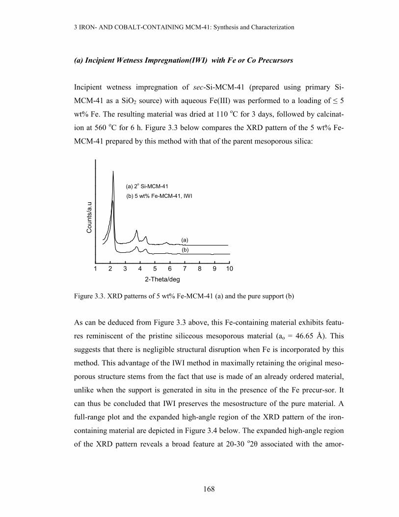
Incipient wetness impregnation of sec-Si-MCM-41 (prepared using primary Si-
MCM-41 as a SiO2 source) with aqueous Fe(III) was performed to a loading of ≤ 5
wt% Fe. The resulting material was dried at 110 oC for 3 days, followed by calcinat-
ion at 560 oC for 6 h. Figure 3.3 below compares the XRD pattern of the 5 wt% Fe-
MCM-41 prepared by this method with that of the parent mesoporous silica:
1 2 3 4 5 6 7 8 9 10
(b) 5 wt% Fe-MCM-41, IWI
(a) 2o Si-MCM-41
(b)
(a)
Counts/a.u
2-Theta/deg
Figure 3.3. XRD patterns of 5 wt% Fe-MCM-41 (a) and the pure support (b)
As can be deduced from Figure 3.3 above, this Fe-containing material exhibits featu-
res reminiscent of the pristine siliceous mesoporous material (ao = 46.65 Å). This
suggests that there is negligible structural disruption when Fe is incorporated by this
method. This advantage of the IWI method in maximally retaining the original meso-
porous structure stems from the fact that use is made of an already ordered material,
unlike when the support is generated in situ in the presence of the Fe precur-sor. It
can thus be concluded that IWI preserves the mesostructure of the pure material. A
full-range plot and the expanded high-angle region of the XRD pattern of the iron-
containing material are depicted in Figure 3.4 below. The expanded high-angle region
of the XRD pattern reveals a broad feature at 20-30 o2θ associated with the amor-

3 IRON- AND COBALT-CONTAINING MCM-41: Synthesis and Characterization
169
phous nature of the silica walls in MCM-41, and a small extent of aggregate-ion of
the iron species (Figure 3.4 insert).
Figure 3.4. The XRD pattern of 5 wt% Fe-MCM-41 prepared by IWI of sec-Si-MCM-41
calcined at 560 oC for 6 h. Insert: Expanded high-angle region, * represents Fe2O3.
The effect of increasing the Fe content in Fe-MCM-41 prepared by IWI of the
primary Si-MCM-41 material has been investigated by XRD. Table 3.1 below shows
the variation of ao values of the resulting Fe-MCM-41 materials as a function of Fe
loading after calcination at 560 oC for 6 h. The lattice parameter remains essentially
constant for the iron content in the range 0 – 20 wt% Fe, showing that IWI method
preserves the lattice dimensions of the parent Si-MCM-41.
10 20 30 40 50 60 700
60
120
**** *
* * * * *
2-Theta/deg
0 10 20 30 40 50 60 70
Counts/a.u
2-Theta/deg

3 IRON- AND COBALT-CONTAINING MCM-41: Synthesis and Characterization
170
Table 3.1 Effects of Fe loading on the XRD properties of Fe-MCM-41 prepared by
IWI.
Wt% Fe ao/Å
0 46.9
1 46.5
2 46.5
5 46.2
10 45.3
20 45.2
A 16 wt% Fe-MCM-41 sample was also prepared by incipient wetness impregnation
using 1 M HNO3 as a solvent for the Fe(III) precursor. The resulting sample was
calcined at two different temperatures and studied by XRD, yielding the results
summarized in Table 3.2.
Table 3.2 Effect of calcination temperature on impregnated 16 wt% Fe-MCM-41
Treatment d100/Ǻ ao/Ǻ
Parent Si-MCM-41 40.2155 46.4
16 wt%Fe/MCM-41, 450 oC, 6 h 39.7627 45.9
16 wt%Fe/MCM-41, 560 oC, 6 h 39.2326 45.3
It is evident from Table 3.2 above that incipient wetness impregnation of the calcined
pure silica material with acidified Fe3+(aq) causes a slight reduction in the unit cell
parameter, although the reduction is not as significant as in the case of isomorphous
substitution during the one-pot synthesis of such materials. There is also a slight
reduction in the lattice parameter on increasing the calcination temperature from 450 oC to 560 oC. The latter observation may suggest an improvement in the thermal

3 IRON- AND COBALT-CONTAINING MCM-41: Synthesis and Characterization
171
stability of the Fe-containing material prepared via this route. More importantly, IWI
with higher metal loadings still preserves the mesoporous structure of Si-MCM-41,
and in addition, gives rise to an iron oxide phase as shown in Figure 3.5 below:
0 10 20 30 40 50 60 70
(006)
(202)
(300)
(214)
(122)/(018)
(116)
(024)
(113)
(110)(104)
(012)
(c) Fe2O
3 (Merck)
(b) 50 wt% Fe-MCM-41, IWI
(a) 16 wt% Fe-MCM-41, IWI
(c)
(b)
(a)
Counts/a.u
2-Theta/deg
Figure 3.5. XRD patterns of Fe-MCM-41 prepared by IWI compared with that of bulk Fe2O3:
(a) 16 wt% Fe-MCM-41, (b) 50 wt% Fe-MCM-41 and (c) bulk Fe2O3.
IWI method achieves maximal retention of the XRD mesoporosity even at high
loadings (50 wt% Fe). The high-angle XRD patterns of the resulting Fe-MCM-41
materials identifies the final Fe phase as hematite by comparison with the XRD
pattern of α-Fe2O3 (Merck). Since such peaks were not readily observed in the XRD
pattern of the lower Fe containing material (e.g., 5 wt% Fe-MCM-41 in Figure 3.4), it
can be concluded that increased Fe content leads to agglomeration or clustering of the
Fe oxide species.
Both 10 and 16 wt% Co-containing materials prepared by a similar IWI method also
show preservation of the mesoporosity, as seen in Figures 3.6 and 3.7.

3 IRON- AND COBALT-CONTAINING MCM-41: Synthesis and Characterization
172
0 10 20 30 40 50 60 70
(440)
(511)
(422)
(400)
(222)
(311)
(220)
(111)
(a)
(b)
(a) 16 wt% Co-MCM-41, IWI
(b) Co3O
4
Counts/a.u
2-Theta/deg
Figure 3.6. XRD patterns of 16 wt% Co-MCM-41 prepared by IWI in 1 M HNO3 solution (a)
and Co3O4 reference sample (b).
In addition to retention of mesoporosity, the metal oxide peaks match those of Co3O4.
We can therefore conclude, as was done for Fe-MCM-41, that there is agglomeration
of the Co species at this loading.
2 4 6 8 10
(b) 10.2 wt% Co-der, IWI, ao = 4.52 nm
(a) Si-MCM-41 parent, ao = 4.62 nm
(210)
(200)
(110)
(100)
(b)
(a)
Counts/a.u
2-Theta/deg
Figure 3.7. Effect of Co incorporation by IWI on XRD patterns: (a) parent Si-MCM-41 and
(b) 10.2 wt% Co-MCM-41.

3 IRON- AND COBALT-CONTAINING MCM-41: Synthesis and Characterization
173
The constancy of the lattice parameter suggests that most of the Co species is to be
found outside the pores of MCM-41 as a separate phase.
(b) Direct Incorporation of aqueous Fe(III) and Co(II) During Synthesis
Materials reported in this section were prepared by dissolving the metal precursor
salts in distilled water prior to addition into the synthesis gel for hydrothermal
synthesis. As has been observed in the synthesis of Si-MCM-41, the pH of the
synthesis gel was also found to play a role in determining the quality of the final Fe-
MCM-41 material prepared by hydrothermal crystallization at 100 oC.
A slight shift in the (100) peak towards higher 2θ values was observed for the Fe-
containing materials when the pH of the synthesis gel was changed from 10 to 12,
implying partial structural collapse from the reduced unit cell size and pore volume
(Figure 3.8). This can also be attributed to the partial solubility of the silica in the
highly alkaline mother liquor.
2 4 6 8 10
1.9 wt% Fe-MCM-41
210200110
100
(b) pH 12, ao = 44.7 angstroms
(a) pH 10, ao = 46.7 angstroms
(b)
(a)
Counts/a.u
2-Theta/deg
Figure 3.8. Effect of synthesis gel pH on the XRD properties of hydrothermally-prepared 1.9
wt% Fe-MCM-41

3 IRON- AND COBALT-CONTAINING MCM-41: Synthesis and Characterization
174
It can be seen from the figure above that both the Fe-MCM-41 materials synthesized
under these conditions are mesoporous and highly ordered. The lattice parameter
change corresponds to a 4.3 % reduction in the unit-cell size with this increase in pH.
Interestingly, a significant decrease in the structure of MCM-41 was observed when
the pH of the synthesis gel was raised from 10 to 12 during the preparation of Si-
MCM-41 (Chapter 2, Figure 2.11). This observation therefore suggests that the
presence of Fe enhances the stability of the silicate at extremely high pH conditions,
where the solubility of SiO2 should be high and structural collapse should take place.
Therefore, pH 10 was chosen for the synthesis of Fe-MCM-41.
Upon increasing the Fe content of the synthesis gel from 1.9 wt% to 8.8 wt% in the
final, calcined material, the synthesis gel became acidic and base addition was needed
to maintain the synthesis pH at 10. This decrease in pH is probably caused by the
interaction of the highly charged Fe3+ with water. The NaOH base used for pH adjust-
ment to 10 was added to the synthesis gel in two forms: as solid NaOH (in the form
of pellets) and also as a 2 M NaOH solution. After similar hydrothermal treatments of
the resulting two synthesis gels, XRD analysis confirmed differences in structural
properties of the final Fe-MCM-41 materials as shown in the figure below:
2 4 6 8 10
(b) pH 10: 1.368 g NaOH, ao = 4.28 nm
(a) pH 10: 17.10 mL 2 M NaOH, ao = 4.39 nm
200
110
100
(b)
(a)
Counts/a.u
2-Theta/deg
Figure 3.9. XRD patterns of 8.8 wt% Fe-MCM-41: solid NaOH versus aqueous NaOH for pH
adjustment.

3 IRON- AND COBALT-CONTAINING MCM-41: Synthesis and Characterization
175
It appears from the figure above that the quality of the Fe-containing material deter-
iorates when solid NaOH is used to bring the gel pH to 10. The mesopore diameter
remains essentially constant (lattice parameters of 4.4 nm versus 4.3 nm). Because of
the superiority of the mesostructure of the material prepared with aqueous NaOH,
liquid-phase pH adjustment was then adopted in the synthesis of high metal contain-
ing MCM-41 materials.
High cobalt loadings in Co-MCM-41 (~8.9 wt%) made by hydrothermal synthesis
were also found to reduce the long-range order in the resulting materials (see Figure
3.10 below):
2 4 6 8 10
0
200
400
600
800
1000
1200
1400
(200)
(110)
(100)
Counts/a.u
2-Theta/deg
Figure 3.10. XRD pattern of 8.9 wt% Co-MCM-41 prepared at 100 oC for 72 h (one-pot
synthesis).
The realization that increasing the metal content (either Fe or Co) beyond 8.8 wt%
led to the breakdown in the MCM-41 type structure prompted an investigation into
finding alternative synthesis methods that could produce high metal-containing mate-
rials with maximum retention of the mesostructure. One of the methods investigated
3 IRON- AND COBALT-CONTAINING MCM-41: Synthesis and Characterization
176
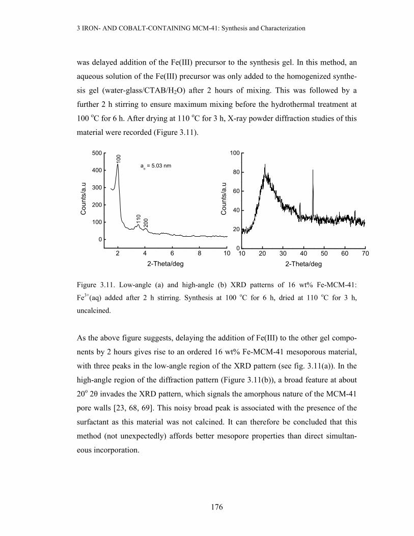
was delayed addition of the Fe(III) precursor to the synthesis gel. In this method, an
aqueous solution of the Fe(III) precursor was only added to the homogenized synthe-
sis gel (water-glass/CTAB/H2O) after 2 hours of mixing. This was followed by a
further 2 h stirring to ensure maximum mixing before the hydrothermal treatment at
100 oC for 6 h. After drying at 110 oC for 3 h, X-ray powder diffraction studies of this
material were recorded (Figure 3.11).
Figure 3.11. Low-angle (a) and high-angle (b) XRD patterns of 16 wt% Fe-MCM-41:
Fe3+(aq) added after 2 h stirring. Synthesis at 100 oC for 6 h, dried at 110 oC for 3 h,
uncalcined.
As the above figure suggests, delaying the addition of Fe(III) to the other gel compo-
nents by 2 hours gives rise to an ordered 16 wt% Fe-MCM-41 mesoporous material,
with three peaks in the low-angle region of the XRD pattern (see fig. 3.11(a)). In the
high-angle region of the diffraction pattern (Figure 3.11(b)), a broad feature at about
20o 2θ invades the XRD pattern, which signals the amorphous nature of the MCM-41
pore walls [23, 68, 69]. This noisy broad peak is associated with the presence of the
surfactant as this material was not calcined. It can therefore be concluded that this
method (not unexpectedly) affords better mesopore properties than direct simultan-
eous incorporation.
10 20 30 40 50 60 700
20
40
60
80
100
Counts/a.u
2-Theta/deg
2 4 6 8 10
0
100
200
300
400
500
ao = 5.03 nm
200110
100
Counts/a.u
2-Theta/deg

3 IRON- AND COBALT-CONTAINING MCM-41: Synthesis and Characterization
177
Other high iron-containing mesoporous materials were prepared by replacing water-
glass with calcined Si-MCM-41 for a SiO2 source for the isomorphous substitution
with aqueous Fe(III). This synthesis was done at 100 oC for 48 h using Si-MCM-41
samples prepared from different SiO2 sources. Tables 3.3 and 3.4 below summarize
the XRD properties of the 16 wt% Fe-MCM-41 materials so obtained:
Table 3.3. XRD data for 16 wt% Fe-MCM-41 made with calcined Si-MCM-41
(which was made from a mixture of fumed SiO2 and water-glass as SiO2 precursor) as
SiO2 source.
Treatment d100/Ǻ ao/Ǻ
As-synthesized 42.3370 48.9
Calcined 560 oC, 3 hours 39.3200 45.4
Calcined 560 oC, 6 hours 38.8015 44.8
Table 3.4. XRD data for 16 wt% Fe-MCM-41 made with calcined Si-MCM-41
(which was made from only water-glass as SiO2 precursor) as SiO2 source.
Treatment d100/Ǻ ao/Ǻ
As-synthesized 40.7727 47.1
560 oC, 6 hours 36.0304 41.6
560 oC, 10 hours 37.7587 43.6
As Tables 3.3 and 3.4 above demonstrate, all the Fe-containing MCM-41 materials
prepared through this route are mesporous, with lattice parameters above 40 Å. In
addition, the data in each table suggest that the materials are thermally stable,
showing little sensitivity to heat treatment. The Fe-MCM-41 material prepared from
Si-MCM-41 that was derived from a dual silica source (fumed SiO2 + water-glass)
suffers little lattice contraction upon calcination at 560 oC for 6 h, as compared to that
obtained from Si-MCM-41 derived from water-glass as a sole SiO2 source, i.e. 8.4 %

3 IRON- AND COBALT-CONTAINING MCM-41: Synthesis and Characterization
178
contraction versus 11.7 % contraction respectively. This observation suggests that the
material obtained from Si-MCM-41 from a dual SiO2 source is thermally more stable.
It has already been demonstrated that secondary synthesis using Si-MCM-41 as a
SiO2 source produce thicker and more crystalline pore walls in the resulting mesopo-
rous silica [70]. Also, metal oxide peaks were observed in the XRD patterns of these
materials.
(c) Acid Mediated Incorporation of Fe during Synthesis
This method of transition metal incorporation was adopted so as to avoid the prema-
ture polycondensation of iron hydroxides in the highly basic sodium silicate solutions
or gels. In this way, higher Fe or Co could be incorporated into the meso-structure
with retention of the MCM-41 characteristics.
Varying the calcination temperature for the as-synthesized hydrothermally-prepared 5
wt% Fe-MCM-41 material can provide an alternative approach to TGA in estimating
the optimum calcination temperature (Figure 3.12).
0 200 400 600 800
44
45
46
47
48
49
50
51
Lattice parameter (a
o)/Angstroms
Calcination temperature/oC
Figure 3.12. Variation of ao with calcination temperature for 5 wt% Fe-MCM-41 prepared at
100 oC for 2 days.
3 IRON- AND COBALT-CONTAINING MCM-41: Synthesis and Characterization
179
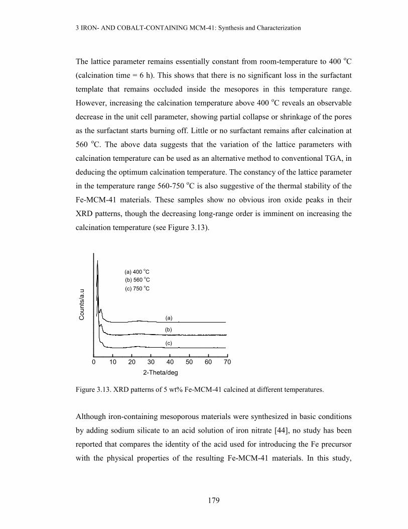
The lattice parameter remains essentially constant from room-temperature to 400 oC
(calcination time = 6 h). This shows that there is no significant loss in the surfactant
template that remains occluded inside the mesopores in this temperature range.
However, increasing the calcination temperature above 400 oC reveals an observable
decrease in the unit cell parameter, showing partial collapse or shrinkage of the pores
as the surfactant starts burning off. Little or no surfactant remains after calcination at
560 oC. The above data suggests that the variation of the lattice parameters with
calcination temperature can be used as an alternative method to conventional TGA, in
deducing the optimum calcination temperature. The constancy of the lattice parameter
in the temperature range 560-750 oC is also suggestive of the thermal stability of the
Fe-MCM-41 materials. These samples show no obvious iron oxide peaks in their
XRD patterns, though the decreasing long-range order is imminent on increasing the
calcination temperature (see Figure 3.13).
0 10 20 30 40 50 60 70
(c) 750 oC
(b) 560 oC
(a) 400 oC
(c)
(b)
(a)Counts/a.u
2-Theta/deg
Figure 3.13. XRD patterns of 5 wt% Fe-MCM-41 calcined at different temperatures.
Although iron-containing mesoporous materials were synthesized in basic conditions
by adding sodium silicate to an acid solution of iron nitrate [44], no study has been
reported that compares the identity of the acid used for introducing the Fe precursor
with the physical properties of the resulting Fe-MCM-41 materials. In this study,

3 IRON- AND COBALT-CONTAINING MCM-41: Synthesis and Characterization
180
various acids have been used to assist the one-pot incorporation of Fe to attain
loadings of 8.8 wt%. These included HNO3, maleic acid, oxalic acid, tartaric acid and
DL-malic acid.
All the resulting acid-assisted 8.8 wt % Fe-MCM-41 materials obtained by hydrother-
mal synthesis at 100 oC for 2 days show excellent mesoporous properties in their
XRD patterns. The lattice parameters for these materials vary with acid identity as
shown in Figure 3.14
Tart Tart MaleicMaleic Oxal EDTA Nit
10
20
30
40
50calc.
calc.calc.calc.
uncalc.
calc.
uncalc.
ao/Angstroms
Acid identity
Figure 3.14. Lattice parameters for 8.8 wt% Fe-MCM-41 prepared at 100 oC for 2 days using
various acids to add the Fe precursor. Key to the figure: Tart = tartaric acid, Maleic = maleic
acid, Oxal = oxalic acid, EDTA = ethylenediaminetetraacetic acid and Nit = nitric acid.
Figure 3.14 shows by way of ao values that the resulting Fe-MCM-41 materials are all
characteristic of mesoporous materials. All the lattice parameters remain above 40 Å,
even after calcination. Another feature observable from the plot is the reduction in the
lattice parameter upon calcination of some of the materials, attributable to the partial
collapse of the porous structure as the surfactant template is decomposed. The high
lattice parameter of the material made with a nitric acid solution of Fe(III) suggests a
high mesoporosity of this material relative to the other studied materials. The
mesoporous character of these materials is supported by the BET surface areas in
3 IRON- AND COBALT-CONTAINING MCM-41: Synthesis and Characterization
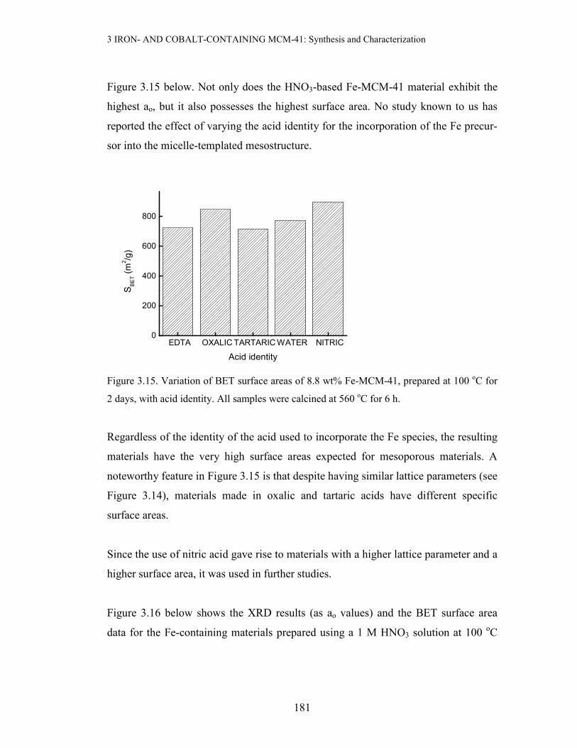
181
Figure 3.15 below. Not only does the HNO3-based Fe-MCM-41 material exhibit the
highest ao, but it also possesses the highest surface area. No study known to us has
reported the effect of varying the acid identity for the incorporation of the Fe precur-
sor into the micelle-templated mesostructure.
EDTA OXALICTARTARICWATER NITRIC0
200
400
600
800
SBET (m
2/g)
Acid identity
Figure 3.15. Variation of BET surface areas of 8.8 wt% Fe-MCM-41, prepared at 100 oC for
2 days, with acid identity. All samples were calcined at 560 oC for 6 h.
Regardless of the identity of the acid used to incorporate the Fe species, the resulting
materials have the very high surface areas expected for mesoporous materials. A
noteworthy feature in Figure 3.15 is that despite having similar lattice parameters (see
Figure 3.14), materials made in oxalic and tartaric acids have different specific
surface areas.
Since the use of nitric acid gave rise to materials with a higher lattice parameter and a
higher surface area, it was used in further studies.
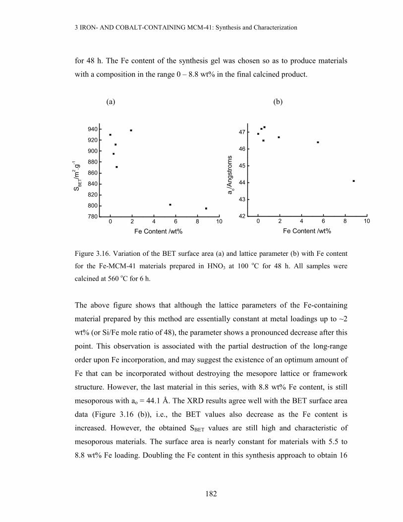
Figure 3.16 below shows the XRD results (as ao values) and the BET surface area
data for the Fe-containing materials prepared using a 1 M HNO3 solution at 100 oC
3 IRON- AND COBALT-CONTAINING MCM-41: Synthesis and Characterization
182
for 48 h. The Fe content of the synthesis gel was chosen so as to produce materials
with a composition in the range 0 – 8.8 wt% in the final calcined product.
(a) (b)
Figure 3.16. Variation of the BET surface area (a) and lattice parameter (b) with Fe content
for the Fe-MCM-41 materials prepared in HNO3 at 100 oC for 48 h. All samples were
calcined at 560 oC for 6 h.
The above figure shows that although the lattice parameters of the Fe-containing
material prepared by this method are essentially constant at metal loadings up to ~2
wt% (or Si/Fe mole ratio of 48), the parameter shows a pronounced decrease after this
point. This observation is associated with the partial destruction of the long-range
order upon Fe incorporation, and may suggest the existence of an optimum amount of
Fe that can be incorporated without destroying the mesopore lattice or framework
structure. However, the last material in this series, with 8.8 wt% Fe content, is still
mesoporous with ao = 44.1 Å. The XRD results agree well with the BET surface area
data (Figure 3.16 (b)), i.e., the BET values also decrease as the Fe content is
increased. However, the obtained SBET values are still high and characteristic of
mesoporous materials. The surface area is nearly constant for materials with 5.5 to
8.8 wt% Fe loading. Doubling the Fe content in this synthesis approach to obtain 16
0 2 4 6 8 10780
800
820
840
860
880
900
920
940
SBET/m
2.g
-1
Fe Content /wt%
0 2 4 6 8 1042
43
44
45
46
47
ao/Angstroms
Fe Content /wt%
3 IRON- AND COBALT-CONTAINING MCM-41: Synthesis and Characterization
183
wt% Fe-MCM-41 resulted in no (100) peak in the XRD pattern, but the material
possessed a reasonably high surface area (552 m2/g). This surface area may suggest
mesoporosity in the material lacking long-range order. Raman spectroscopy has also
shown a decrease in the area of the peak at 3476 cm-1 (Figure 3.59), suggesting that
surface silanol groups are used to anchor Fe(III). ESR spectra of representative
materials, for example Figures 3.48 and 3.49, showed partial incorporation of Fe(III)
into the silicate framework.
(d) Acid-Mediated Incorporation of Co
The monometallic cobalt-based mesoporous materials with varying cobalt contents
have also been prepared in a method similar to the above method for Fe-based
materials (i.e. hydrothermal one-pot synthesis at 100 oC for 48 h with 1 M HNO3
solution). Table 3.5 below shows the XRD results obtained for the calcined samples
of Co-MCM-41.
Table 3.5. HNO3-assisted Co(II) incorporation into the MCM-41 synthesis gel, and
its effect on the properties of the resulting Co-MCM-41 materials.
Gel Si/Co mol
ratio
Wt% Co ao/Å SBET (m2/g
sample)
SBET (m2/g
support)a
∞ 0 46.9 930 930
34.6 2.8 47.2 865 890
11.5 7.9 45.6 - -
6.9 12.5 47.5 652 745
3.5 21.9 - (no d100 peak) 522 668 aThe surface area of SiO2 has been corrected for the contribution from the Fe component.
The standard deviation of the average lattice parameter for these materials is ± 0.35
Å, regardless of the Co content. Thus the pore dimensions are essentially constant in

3 IRON- AND COBALT-CONTAINING MCM-41: Synthesis and Characterization
184
this range of cobalt content. The d100 peak was completely absent in the XRD pattern
of the 21.9 wt% Co-MCM-41, signaling structural destruction or loss of the long-
range order achieved at high metal contents. This breakdown in mesoporosity of the
21.9 wt% sample is supported by the relatively lower BET surface area, 522 m2/g
(although reasonably high and suggestive of mesoporosity). The data in the last
column show that the effect of cobalt incorporation during synthesis is to lower the
surface area of the pure silica MCM-41
(e) Simultaneous Incorporation of Fe and Co by the Acid-Mediated Route
A bimetallic (7.8 wt% Fe, 11.5 wt% Co)-MCM-41 sample was prepared at 100 oC for
48 h using a 1 M HNO3 solution of the metal precursors. Comparison of this material
with its monometallic Fe-MCM-41 analogue is illustrated in Figure 3.17.
2 4 6 8 10
200
110
100
(b) 7.8 wt% Fe, 11.5 wt% Co
(a) 8.8 wt% Fe
(b)
(a)
Counts/a.u
2-Theta/deg
Figure 3.17. XRD patterns of a bimetallic and monometallic MCM-41 prepared at 100 oC for
2 days with metal precursors in 1 M HNO3: (a) 8.8 wt% Fe-MCM-41 (ao = 44.1 Å), and (b)
(7.8 wt% Fe, 11.5 wt% Co)-MCM-41 (ao = 44.3 Å).
Figure 3.17 further demonstrates the retention of mesoporosity upon the inclusion of
two different metals in the synthesis gel. It further shows that the high total metal
3 IRON- AND COBALT-CONTAINING MCM-41: Synthesis and Characterization
185
content affects the long-range order of the resulting bimetallic system. It is to be
noted from this figure that the lattice parameter of the monometallic Fe species (44.1
Å) is the same as that of the bimetallic material (44.3 Å). In accordance with the
observations already mentioned in this chapter, it is expected that increased metal
contents should result in materials with lower lattice parameters as a result of
structural collapse caused by the presence of foreign atoms. However, the total metal
content of the bimetallic mesoporous material is 19.3 wt%, yet the lattice parameter
matches that of the monometallic mesoporous material. The amount of Fe precursor
in each case was the same (5 g).
(f) Base-Mediated Incorporation of Fe During Synthesis
Since only low Fe or Co loadings (~9 wt%) could be introduced into the synthesis gel
with retention of the mesostructure in the final material, an alternative approach was
to add the Fe precursor as a gelatinous hydroxide precipitate (slurry) prior to synthes-
is both under hydrothermal and ambient temperature conditions. Another reason of
going this synthesis route is because Fe(OH)3 is an intermediate in the synthesis of
bulk Fe2O3, which could help identify the phase resulting from the interaction with
the MCM-41 synthesis recipe. Varying the synthesis time, temperature and the point
of metal hydroxide slurry addition (either before or after the silicate precursor)
showed interesting properties for the resulting metallosilicates. The results of such
syntheses are discussed below:
1. Variation of the type of base used
Various bases have been used to precipitate the Fe(III) prior to stirring the suspension
into the recipe for synthesizing Si-MCM-41 in order to prepare 16 wt% of the metal-
containing derivatives of the mesoporous material. After hydrothermal crystallization
at 100 oC for 2 days and subsequent calcination, the effect of the nature of the precipi-
3 IRON- AND COBALT-CONTAINING MCM-41: Synthesis and Characterization
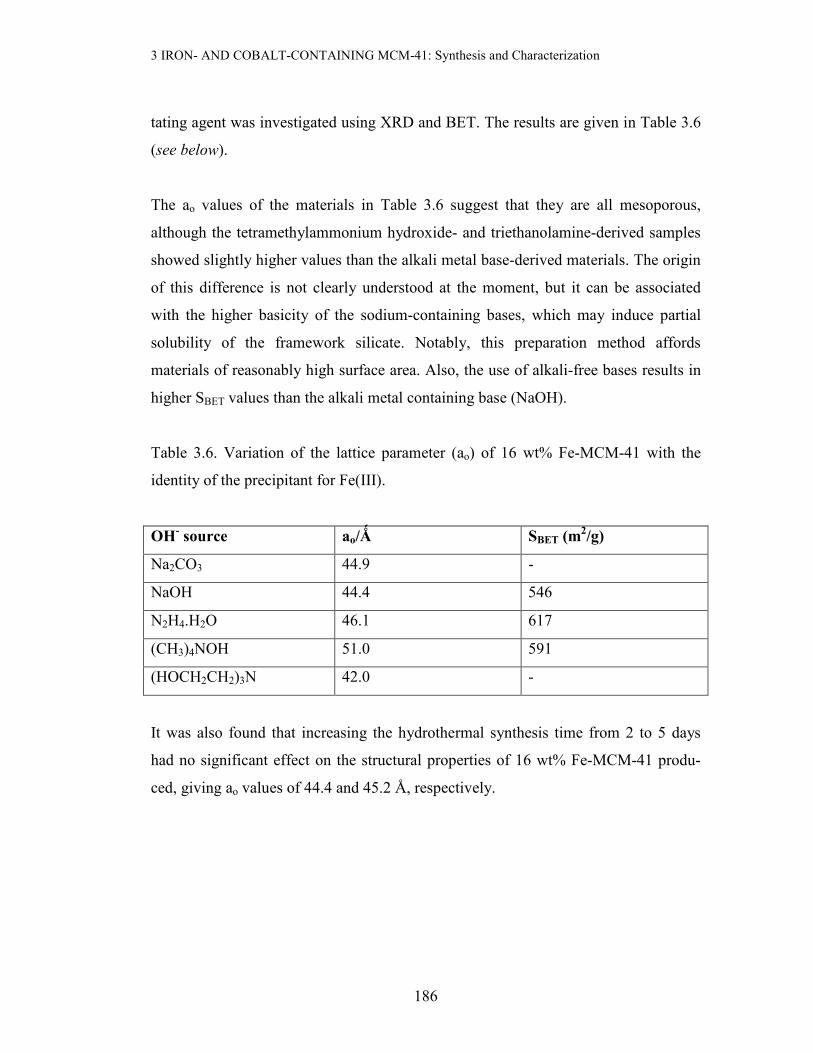
186
tating agent was investigated using XRD and BET. The results are given in Table 3.6
(see below).
The ao values of the materials in Table 3.6 suggest that they are all mesoporous,
although the tetramethylammonium hydroxide- and triethanolamine-derived samples
showed slightly higher values than the alkali metal base-derived materials. The origin
of this difference is not clearly understood at the moment, but it can be associated
with the higher basicity of the sodium-containing bases, which may induce partial
solubility of the framework silicate. Notably, this preparation method affords
materials of reasonably high surface area. Also, the use of alkali-free bases results in
higher SBET values than the alkali metal containing base (NaOH).
Table 3.6. Variation of the lattice parameter (ao) of 16 wt% Fe-MCM-41 with the
identity of the precipitant for Fe(III).
OH- source ao/Ǻ SBET (m
2/g)
Na2CO3 44.9 -
NaOH 44.4 546
N2H4.H2O 46.1 617
(CH3)4NOH 51.0 591
(HOCH2CH2)3N 42.0 -
It was also found that increasing the hydrothermal synthesis time from 2 to 5 days
had no significant effect on the structural properties of 16 wt% Fe-MCM-41 produ-
ced, giving ao values of 44.4 and 45.2 Å, respectively.

3 IRON- AND COBALT-CONTAINING MCM-41: Synthesis and Characterization
187
2. Iron content
Figure 3.18 shows the effect of the iron content on the new material using Fe(OH)3 as
the source of iron. All the Fe-containing MCM-41 materials in Figure 3.18 possess
long-range order in their pore systems. An increase in Fe content is accompanied by a
decrease in the intensity of the (100) peak, and the disappearance of some higher
order peaks in the region 2o < 2θ < 6o in the XRD patterns. Metal oxide peaks
become increasingly apparent when the Fe loading exceeds 5 wt% Fe, and these
peaks are characteristic of Fe2O3. Therefore, the Fe species is well dispersed in the
resulting silicate when low loadings are used. In contrast with Fe addition from
aqueous solutions, this method preserves the mesostructure in the final material even
at loadings of up to 20 wt% (see appendix A.3). The broad line of low intensity in the
XRD patterns of MCM-41 and HMS–type materials at about 20o 2θ suggests that the
inorganic walls in these materials are amorphous [23, 68, 69].
0 10 20 30 40 50 60 70
*
*
*
(d)
(c)
(b)
(a)
(300)
(214)
(122)/(018)
(116)
(024)
(202)
(113)
(110)
(104)
(012)
Counts/a.u
2-Theta/deg
Figure 3.18. XRD patterns of Fe-MCM-41 prepared via the OH- route and calcined at 560 oC
for 6 h: (a) 5 wt% Fe-MCM-41, (b) 10 wt% Fe-MCM-41, (c) 16 wt% Fe-MCM-41, and (d)
bulk Fe2O3. The peak marked * is a contribution from the Al sample holder.
3 IRON- AND COBALT-CONTAINING MCM-41: Synthesis and Characterization
188
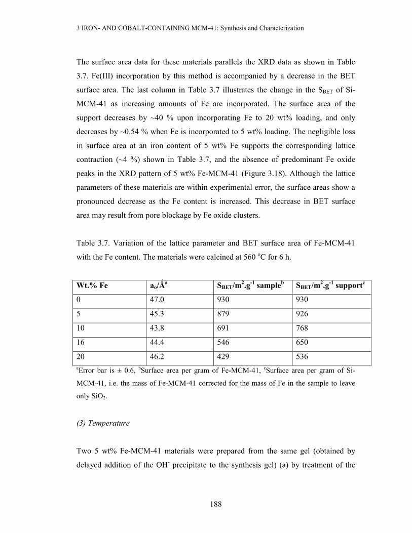
The surface area data for these materials parallels the XRD data as shown in Table
3.7. Fe(III) incorporation by this method is accompanied by a decrease in the BET
surface area. The last column in Table 3.7 illustrates the change in the SBET of Si-
MCM-41 as increasing amounts of Fe are incorporated. The surface area of the
support decreases by ~40 % upon incorporating Fe to 20 wt% loading, and only
decreases by ~0.54 % when Fe is incorporated to 5 wt% loading. The negligible loss
in surface area at an iron content of 5 wt% Fe supports the corresponding lattice
contraction (~4 %) shown in Table 3.7, and the absence of predominant Fe oxide
peaks in the XRD pattern of 5 wt% Fe-MCM-41 (Figure 3.18). Although the lattice
parameters of these materials are within experimental error, the surface areas show a
pronounced decrease as the Fe content is increased. This decrease in BET surface
area may result from pore blockage by Fe oxide clusters.
Table 3.7. Variation of the lattice parameter and BET surface area of Fe-MCM-41
with the Fe content. The materials were calcined at 560 oC for 6 h.
Wt.% Fe ao/Ǻa
SBET/m2.g
-1 sample
b SBET/m
2.g
-1 support
c
0 47.0 930 930
5 45.3 879 926
10 43.8 691 768
16 44.4 546 650
20 46.2 429 536 aError bar is ± 0.6, bSurface area per gram of Fe-MCM-41, cSurface area per gram of Si-
MCM-41, i.e. the mass of Fe-MCM-41 corrected for the mass of Fe in the sample to leave
only SiO2.
(3) Temperature
Two 5 wt% Fe-MCM-41 materials were prepared from the same gel (obtained by
delayed addition of the OH- precipitate to the synthesis gel) (a) by treatment of the

3 IRON- AND COBALT-CONTAINING MCM-41: Synthesis and Characterization
189
mixture at reflux (~97 oC) for 45 minutes, and (b) by carrying out synthesis at room
temperature for 4 days, followed by calcination of both samples at 560 oC for 6 h.
The XRD patterns of the resulting materials are shown in Figure 3.19 (next page). As
can be seen from Figure 3.18, the mesoporous properties of the MCM-41-type
materials are improved by synthesis temperature. The material obtained at 97 oC is
more ordered (low-angle XRD peaks) than that obtained at room temperature. In
addition, the iron oxide phase seems to be more dispersed in the hydrothermally-
synthesized material, as shown by the relatively weak metal oxide peaks above 30o
2θ. This may result from the partial solubility of Fe(OH)3 at high temperatures,
allowing good mixing and incorporation of Fe into the framework. The TPR profile
of this room temperature-synthesized material also confirms the presence of reducible
iron oxides (see Figure 3.40).
0 10 20 30 40 50 60 70
*
*
(b) Room T for 4 days
(a) refluxed 45 min at 97 oC
(b)
(a)
Counts/a.u
2-Theta/deg
Figure 3.19. The XRD patterns of 5 wt% Fe-MCM-41 prepared by adding Fe(OH)3 to the
synthesis gel and carrying out the synthesis (a) at 97 oC for 45 minutes and (b) at room
temperature for 4 days. Both materials were dried and calcined at 560 oC for 6 h. *Contam-
ination from the Al sample holder.

3 IRON- AND COBALT-CONTAINING MCM-41: Synthesis and Characterization
190
(g) Base-mediated incorporation of Co
Cobalt-containing materials of composition (0 – 16) wt% Co/MCM-41 have also
been prepared via the hydroxide route at 100 oC over a 2 day period. Table 3.8 details
the properties of the resulting Co-containing materials, obtained from physicochemic-
al characterization.
Table 3.8. Variation of ao and SBET with Co content for Co-MCM-41 prepared via the
OH- route at 100 oC for 2 days (calcined at 560 oC for 6 h).
Wt% Co ao/Ǻa SBET/m
2.g
-1 sample
b SBET/m
2.g
-1 support
c
0 47 930 930
5 45.4 - -
10 45.7 - -
16 46.9 751 894 aError bar = ± 0.34 Å, bSurface area per gram of Co-MCM-41, cSurface area per gram of
SiO2, SBET was not measured for the 5 and 10 wt% Co-MCM-41 materials.
The trend in the lattice parameters shown in the table above is analogous to that
observed in Fe-MCM-41 prepared via a similar route (Table 3.7). Notably, the lattice
parameters of the cobalt-containing MCM-41 also suggest the materials remain meso-
porous in this range of cobalt contents. The XRD patterns of the 5 and 16 wt% Co-
MCM-41 in Figure 3.20 supplement the mesoporosity judged from the lattice
parameters, and also confirms retention of the long-range order in the final materials.
The data also show that the specific surface area of the mesoporous silica support
decreases by 3.9 % when the support is generated in situ during the preparation of 16
wt% Co-MCM-41. This agrees with the observation on lattice parameters in XRD
studies, where a 0.4 % decrease was observed.

3 IRON- AND COBALT-CONTAINING MCM-41: Synthesis and Characterization
191
10 20 30 40 50 60 70
* *
**
*
*
*
*
*
**
*
(b) 16 wt% Co-MCM-41, ao = 4.57 nm
(a) 5 wt% Co-MCM-41, ao = 4.54 nm
(b)
(a)Counts/a.u
2-Theta/deg
Figure 3.20. XRD patterns of Co-MCM-41 prepared by the OH- route at 100oC for 48 h and
calcined at 560 oC for 6 h. * designates Co3O4 peaks
Figure 3.20 again supports an analogous trend to that observed with the Fe-containing
material. The metal oxide peaks grow more intense with an increase in the metal
content of the synthesis mixture. The d100 peak is at about the same position in both
the 5 wt% and the 16 wt% Co-MCM-41 materials, suggesting similar ao values as
shown in the figure. Although both materials exhibit long-range order (four XRD
peaks below 10o), the 5 wt% Co-MCM-41 has a superior mesostructural order as
shown by the intensity and resolution of the low-angle peaks.
A 10 wt% Co-MCM-41 (material prepared from hydrothermal synthesis using
Co(OH)2 slurry as Co precursor) reduced in H2 during TPR analysis up to 800 oC,
showed the XRD pattern depicted in Figure 3.21 (b) (on the next page). The lattice
parameter did not change in the reduced sample, signifying stability of the pore
structure in a H2 atmosphere up to 800 oC. The peak at 45o in the XRD pattern of the
reduced sample is a contribution from the Al sample holder. The absence of any
cobalt oxide peaks in the reduced sample suggests that the Co exists as nanoclusters
inside the channels of the SiO2 matrix.

3 IRON- AND COBALT-CONTAINING MCM-41: Synthesis and Characterization
192
(a) (b)
Figure 3.21. XRD patterns of 10 wt% Co-MCM-41 prepared hydrothermally via the
hydroxide route: (a) calcined at 560 oC for 6 h (ao = 45.7 Å), and (b) after a TPR experiment
(ao = 45.6 Å). The symbol + denotes the Co3O4 phase and * may be a contribution from the
Al sample holder.
Room temperature synthesis of 16 wt% Co-MCM-41 via the OH- precipitate route
over 5 days also produce materials of high hexagonal order (Figure 3.22).
0 10 20 30 40 50 60 70
(a) As-synthesized, ao = 5.03 nm
(b) 560 oC for 6 h, a
o = 4.62 nm
(a)
(b)
Counts/a.u
2-Theta/deg
Figure 3.22. XRD patterns of 16 wt% Co-MCM-41 (5 day synthesis at RT, OH- route).
0 10 20 30 40 50 60 70
*
Counts/a.u
2-Theta/deg
0 10 20 30 40 50 60 70
++*+++
Counts/a.u
2-Theta/deg

3 IRON- AND COBALT-CONTAINING MCM-41: Synthesis and Characterization
193
The above figure reveals that the materials are ordered and mesoporous (XRD peaks
at low 2θ values). Upon calcination of the material, the broad XRD feature at about
20o decreased significantly and the metal oxide peaks became more intense. The
metal oxide phase (also observed in similar material prepared at 100 oC for 2 days)
can be positively identified by comparison with synthetic Co3O4 as shown in Figure
3.23 below:
10 20 30 40 50 60 70
(c) 16 % Co-M41 (100oC 2 d)
(b) 16 % Co-M41 (RT, 5 d)
(a) Co3O
4
(c)
(b)
(a)
Counts/a.u
2-Theta/deg
Figure 3.23. High-angle XRD patterns of Co3O4 (a), 16 wt% Co-MCM-41 prepared at RT for
5 days (b), and 16 wt% Co-MCM-41 prepared at 100 oC for 2 days (c).
Regardless of the preparation temperature for the Co-MCM-41 material, the metal
oxide region of the diffractogram is the same. These diffractograms confirm that the
cobalt oxide phase obtained is predominantly found as Co3O4, compatible with the
findings for cobalt-based materials prepared by pore volume impregnation.

3 IRON- AND COBALT-CONTAINING MCM-41: Synthesis and Characterization
194
(h) Comparisons between Me-MCM-41 (Me = Fe, Co, Ru) prepared by the base
precipitate
Hydrothermal synthesis at 100 oC for 48 h of 16 wt% Me-MCM-41 (Me = Fe, Co,
Ru) using NaOH precipitates of metal precursors produced materials with XRD
properties shown in Figure 3.24.
0 10 20 30 40 50 60 70
(c) 16 wt% Ru, ao= 3.94 nm
(b) 16 wt% Fe, ao= 4.44 nm
(a) 16 wt% Co, ao= 4.69 nm
(c)
(b)
(a)
Counts/arb. units
2-Theta/degrees
Figure 3.24. XRD patterns of 16 wt% Me-MCM-41 prepared via the NaOH precipitate route:
Me = Co (a), Fe (b) and Ru (c). All materials were calcined at 560 oC for 6 h.
It is evident that the long-range order of the mesoporous support is influenced by the
size of the heteroatom incorporated (number of low-angle peaks). The order of impro-
ved mesostructure is 16 wt% Ru- < 16 wt% Fe- < 16 wt% Co-MCM-41. This order is
also supported by the BET data in Table 3.9, which shows an analogous decrease in
SBET. The higher BET surface area and lattice parameter of Co-MCM-41 may suggest
the ease of incorporating the smaller Co(II) into the silicate lattice as compared to the
Fe- and Ru-based counterparts. Equivalently, both ao and SBET decrease down the
group for Fe and Ru derivatives of MCM-41 as a result of the increasing size as the
group is transcended.

3 IRON- AND COBALT-CONTAINING MCM-41: Synthesis and Characterization
195
Table 3.9. XRD and BET surface area data for 16 wt% Me-MCM-41 (Me = Si, Fe,
Co and Ru) prepared by the metal hydroxide route at different temperatures.
Metal Lattice parameter/Å SBET (m2/g)
Hydrothermal synthesis (100 oC for 48 h)
Si 47 930
Co 46.9 751
Fe 44.4 546
Ru 39.4 223
Room temperature synthesis, 5 days
Co 46.2 886
Fe 44.9 750
Although no TEM was done on these samples, the appearance of intense RuOx peaks
in the high-angle region of the XRD pattern can be taken as a sign that most of the Ru
species is outside the framework structure, and predominantly on the surface. In fact,
the ESR spectrum of Ru-MCM-41 (Figure 3.52) reveals the presence of two
coordination environments, with g ~ 4.0 and g ~ 2 respectively. Interestingly,
applying different synthesis conditions (room temperature for 5 days) confirm the
effect seen in hydrothermally-prepared samples (in terms of ao and SBET).
Table 3.10 compares one-pot synthesis and incipient wetness impregnation for the
preparation of the 16 wt% Fe-MCM-41 and 16 wt% Co-MCM-41. The one-pot
synthesis involved precipitating the metal precursor prior to hydrothermal synthesis
(48 h at 100 oC), while incipient wetness impregnation method used acidified Fe(III)
or Co(II) precursors.

3 IRON- AND COBALT-CONTAINING MCM-41: Synthesis and Characterization
196
Table 3.10. A comparison of ao values of 16 wt% Fe- and Co-MCM-41 as influenced
by the synthesis method
Sample Synthesis d100/Ǻ ao/Ǻ
Fe/MCM-41 one-pot 38.5 44.4
Fe/MCM-41 Impregnation 39.2 45.3
Co-MCM-41 one-pot 40.6 46.9
Co-MCM-41 Impregnation 40.2 46.4
For the materials made by incipient wetness impregnation of Si-MCM-41 using
acidified solutions of the metal precursors, the cobalt-based materials result in a
slightly larger unit cell parameter as compared to their iron-based counterparts. This
agrees well with the observations for the materials of similar metal loadings prepared
by in situ techniques.
In general, Co is better than Fe in preserving the mesoporous characteristics of
MCM-41 when these metals are heterogenized into the synthesis gel during synthesis.
3.3.2 High Resolution Transmission Electron Microscopy (HRTEM)
This study concerned only the Fe-containing MCM-41 materials, and is complement-
ary to the data reported in previous sections. To circumvent the Fe agglomeration
problem usually encountered in the one-pot synthesis using water-glass as a silica
source, a number of experiments involving the use of TEOS were also undertaken.
Some of these materials have been extensively used in Chapter 4 as supports for Au
catalysts, and the catalysts were used to study the CO oxidation reaction (Chapter 5).
Figure 3.25 shows the (a) micrograph and (b) EDS spectrum of 16 wt% Fe-MCM-41
prepared by IWI using a nitric acid solution of Fe(III).
3 IRON- AND COBALT-CONTAINING MCM-41: Synthesis and Characterization
197
(a) (b)
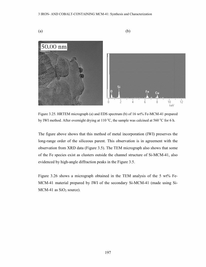
Figure 3.25. HRTEM micrograph (a) and EDS spectrum (b) of 16 wt% Fe-MCM-41 prepared
by IWI method. After overnight drying at 110 oC, the sample was calcined at 560 oC for 6 h.
The figure above shows that this method of metal incorporation (IWI) preserves the
long-range order of the siliceous parent. This observation is in agreement with the
observation from XRD data (Figure 3.5). The TEM micrograph also shows that some
of the Fe species exist as clusters outside the channel structure of Si-MCM-41, also
evidenced by high-angle diffraction peaks in the Figure 3.5.
Figure 3.26 shows a micrograph obtained in the TEM analysis of the 5 wt% Fe-
MCM-41 material prepared by IWI of the secondary Si-MCM-41 (made using Si-
MCM-41 as SiO2 source).
3 IRON- AND COBALT-CONTAINING MCM-41: Synthesis and Characterization
198
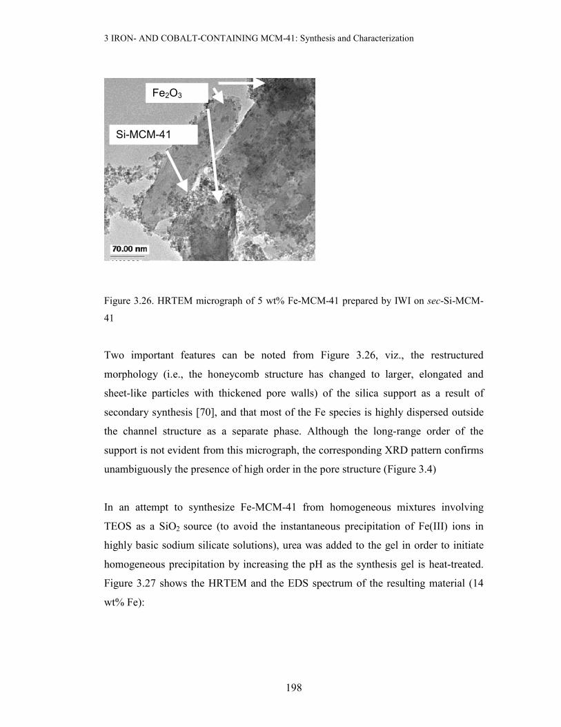
Figure 3.26. HRTEM micrograph of 5 wt% Fe-MCM-41 prepared by IWI on sec-Si-MCM-
41
Two important features can be noted from Figure 3.26, viz., the restructured
morphology (i.e., the honeycomb structure has changed to larger, elongated and
sheet-like particles with thickened pore walls) of the silica support as a result of
secondary synthesis [70], and that most of the Fe species is highly dispersed outside
the channel structure as a separate phase. Although the long-range order of the
support is not evident from this micrograph, the corresponding XRD pattern confirms
unambiguously the presence of high order in the pore structure (Figure 3.4)
In an attempt to synthesize Fe-MCM-41 from homogeneous mixtures involving
TEOS as a SiO2 source (to avoid the instantaneous precipitation of Fe(III) ions in
highly basic sodium silicate solutions), urea was added to the gel in order to initiate
homogeneous precipitation by increasing the pH as the synthesis gel is heat-treated.
Figure 3.27 shows the HRTEM and the EDS spectrum of the resulting material (14
wt% Fe):
Si-MCM-41
Fe2O3

3 IRON- AND COBALT-CONTAINING MCM-41: Synthesis and Characterization
199
(a) (b)
Figure 3.27. HRTEM micrograph (a) and EDS spectrum (b) of 14 wt% Fe material made
from TEOS and urea at 80-90 oC for 24 h.
Instead of getting a material with long-range order and a characteristic hexagonal
pore structure, a well-mixed iron silicate material was obtained with no long-range
order. Surprisingly, this material had a high surface area (723 m2/g).
A similar observation to the above was obtained when a synthesis gel comprising
TEOS, CTAB, Fe(NO3)3.9H2O, urea and water was pumped with an aerosol gener-
ator and passed through a horizontal quartz tube maintained at 125 oC. A nominal Fe
content of 7.5 wt% Fe relative to SiO2 was used. Figure 3.28 (next page) shows the
HRTEM results of the resulting material. The material was also found to lack long-
range order in the channel system, although the BET surface area (1024 m2/g) was
typical of mesoporous silica.

3 IRON- AND COBALT-CONTAINING MCM-41: Synthesis and Characterization
200
Figure 3.28. HRTEM micrograph of 7.5 wt% Fe-silica material made by the aerosol route at
125 oC.
However, use of water-glass as a SiO2 source produced ordered materials (see Figure
3.29).
Figure 3.29. HRTEM micrograph of 3 wt% Fe-MCM-41 prepared at 80 oC for 6 h. The
material was then calcined at 500 oC for 12 h

3 IRON- AND COBALT-CONTAINING MCM-41: Synthesis and Characterization
201
The material in Figure 3.29 shows high long-range order in the channel system
characteristic of MCM-41, which is supported by the high BET surface area of 1226
m2/g.
A 5 wt% Fe-MCM-41 sample was prepared hydrothermally by using a freshly
prepared Fe(OH)3 slurry as the Fe precursor and water-glass as a SiO2 source. The
synthesis was carried out at 100 oC for 48 h, and the final processed product was
calcined at 560 oC for 6 h. Figure 3.30 below shows micrographs of two different
regions of this calcined product.
Figure 3.30. HRTEM micrographs of two different regions of 5 wt% Fe-MCM-41 prepared
via the OH- route at 100 oC for 2 days.
Although the composite material above is highly ordered, most of the Fe species
exists as a separate phase agglomerated outside the channel structure. The high struct-
ural order is also supported by the corresponding XRD pattern shown in Figure 3.18
(a).

3 IRON- AND COBALT-CONTAINING MCM-41: Synthesis and Characterization
202
3.3.3 Temperature-Programmed Reduction (TPR)
Reducibility is one of the key requirements for supports used in gold catalysis. In this
work, the reducibility of the metal component (Fe or Co) of the mesoporous support
has been investigated using the TPR technique. Fe2O3 (Merck) and synthetic Co3O4
were used as reference materials.
3.3.3.1 TPR studies of Fe-containing MCM-41
The TPR profile of the reference material, Fe2O3, shows two peaks of different sizes
and intensities at 420 and 640 oC, assigned respectively to the reduction processes 3
Fe2O3 + H2 → 2 Fe3O4 + H2O and Fe3O4 + 4 H2 → 3 Fe0 + 4 H2O [71, 72]. Thus, any
reduction peak at ~640 oC should signal reduction to Fe0. The characteristic two-peak
reduction process has been observed in the TPR profiles of 16 wt% Fe-MCM-41
prepared by the IWI method using a nitric acid solution of Fe(III) and Si-MCM-41
(Figure 3.31 (a) and (b)).
200 300 400 500 600 700 800
(c)
640 oC
420 oC
H2 U
ptake/a.u
Temperature/oC
(b)
713 oC442 oC
(a)
672 oC647 oC
563 oC
369 oC
Figure 3.31. TPR profiles of 16 wt% Fe-MCM-41 prepared by IWI: (a) calcined at 450 oC for
12 h, (b) calcined at 560 oC for 6 h, and (c) bulk Fe2O3 reference.

3 IRON- AND COBALT-CONTAINING MCM-41: Synthesis and Characterization
203
The calcination temperature seems to play a role on the reducibility of the 16 wt% Fe-
MCM-41 materials. The material calcined at 450 oC is reduced at lower temperatures
compared to that calcined at 560 oC, suggesting a highly dispersed Fe phase [72] in
the former. These observations also suggest that the Fe species in these materials is in
the form of Fe2O3. The higher temperature peak (e.g., 713 oC) suggests the reduction
of an iron silicate phase formed upon calcination of the material.
The reducibility of 5 wt% Fe-MCM-41 prepared by IWI method using secondary Si-
MCM-41 as support is shown below:
200 300 400 500 600 700 800
H2 U
ptake/a.u
(b)
640 oC
420 oC
Temperature/oC
(a)
387 oC
497 oC
661 oC
Figure 3.32. TPR profiles of (a) 5 wt% Fe-MCM-41 prepared by IWI method using sec-Si-
MCM-41 as a support, calcined at 560 oC for 6 h, (b) bulk Fe2O3.
Principally, the 5 wt% Fe-MCM-41 exhibits two large reduction peaks at 387 and 497 oC. The symmetry of these peaks suggests that they arise from the Fe2O3 → Fe3O4 →
Fe reduction processes, and the smaller peak at 661 oC suggests further reduction to
Fe0. The observed shifts to lower reduction temperatures for the 5 wt% Fe-MCM-41
material (Figure 3.32) suggests that the Fe species in this material is highly dispersed
[72]. This dispersed state of Fe may stem from the use of restructured sec-Si-MCM-
41, which possesses stronger and thicker pore walls than primary Si-MCM-41 [70],
making it more resistant to permeation by metals. Indeed, the XRD pattern of this
3 IRON- AND COBALT-CONTAINING MCM-41: Synthesis and Characterization
204
material shows significant retention of long-range order as seen in Figure 3.4. The
above results also suggest that Fe2O3 is the dominant Fe species.
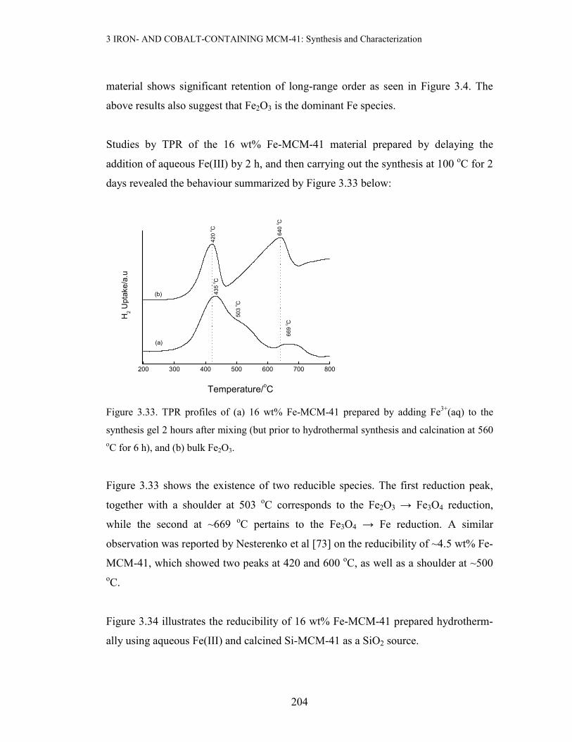
Studies by TPR of the 16 wt% Fe-MCM-41 material prepared by delaying the
addition of aqueous Fe(III) by 2 h, and then carrying out the synthesis at 100 oC for 2
days revealed the behaviour summarized by Figure 3.33 below:
200 300 400 500 600 700 800
Temperature/oC
H2 U
ptake/a.u
640 oC
420 oC
(b)
(a)
669 oC
435 oC
503 oC
Figure 3.33. TPR profiles of (a) 16 wt% Fe-MCM-41 prepared by adding Fe3+(aq) to the
synthesis gel 2 hours after mixing (but prior to hydrothermal synthesis and calcination at 560 oC for 6 h), and (b) bulk Fe2O3.
Figure 3.33 shows the existence of two reducible species. The first reduction peak,
together with a shoulder at 503 oC corresponds to the Fe2O3 → Fe3O4 reduction,
while the second at ~669 oC pertains to the Fe3O4 → Fe reduction. A similar
observation was reported by Nesterenko et al [73] on the reducibility of ~4.5 wt% Fe-
MCM-41, which showed two peaks at 420 and 600 oC, as well as a shoulder at ~500 oC.
Figure 3.34 illustrates the reducibility of 16 wt% Fe-MCM-41 prepared hydrotherm-
ally using aqueous Fe(III) and calcined Si-MCM-41 as a SiO2 source.

3 IRON- AND COBALT-CONTAINING MCM-41: Synthesis and Characterization
205
200 300 400 500 600 700 800
H2 Uptake/a.u
(b)
(a)
640 oC
420 oC
Temperature/oC
433 oC
548 oC
660 o C
Figure 3.34. TPR profile of (a) 16 wt% Fe-MCM-41 prepared hydrothermally from Fe3+(aq)
and Si-MCM-41 as a SiO2 source followed by calcination at 560 oC for 6 h, and (b) bulk
Fe2O3.
The figure above shows the existence of three reducible Fe species. The three
reduction peaks occur in the temperature region where reduction to metallic Fe takes
place, i.e. at 433, 548 and 660 oC. By comparison with the diffractogram of bulk
Fe2O3 the peak at 433 oC is associated with the Fe2O3 → Fe3O4 reduction process,
while the one at 660 oC is associated with the Fe3O4 → Fe reduction. The slight
deviations observed from the reduction temperatures of bulk hematite (420 and 640 oC) are due to the stabilization of iron oxides by the support. The reduction peak
observed at 548 oC is intermediate between the two reduction processes, Fe2O3 →
Fe3O4 and Fe3O4 → Fe0, and can thus be attributed to the reduction of an intermediate
species between Fe3O4 and Fe0 [71], namely FeO → Fe0. This step is rarely observed
in the TPR traces of Fe-containing materials.
Addition of the Fe precursor as a HNO3 (1 M) solution for the hydrothermal synthesis
of 8.8 wt% Fe-MCM-41 at 100 oC for 2 days, produced a material whose TPR profile
is shown in Figure 3.35 (next page) . The TPR profile is dominated by a broad
reduction peak centred at ~431oC, assignable to Fe2O3 → Fe3O4 reduction step. The
11 oC shift to higher reduction temperatures relative to Fe2O3 can be attributed to

3 IRON- AND COBALT-CONTAINING MCM-41: Synthesis and Characterization
206
stabilization of Fe(III) by the silica matrix. The results show no obvious reduction to
metallic Fe, suggesting that the majority of Fe(III) is in the MCM-41 structure.
200 300 400 500 600 700 800
640 oC
420 oC
H2 Uptake/a.u
Temperature/oC
431 oC
(b)
(a)
Figure 3.35. TPR profile of (a) Fe2O3 and (b) 8.8 wt% Fe-MCM-41 prepared by HNO3-
mediated incorporation of Fe(III) (2 days at 100 oC) and calcined at 560 oC for 6 h.
The inclusion of Fe in the synthesis gel for hydrothermal synthesis, in which Fe was
added to the gel as a freshly-precipitated NaOH slurry, was also investigated. Figure
3.36 (next page) illustrates the effect of increasing the Fe content of the synthesis gel
for synthesis at 100 oC for 2 days. A broad, unsymmetrical reduction peak centred at
468 oC is observed in the TPR spectrum of 5 wt% Fe-MCM-41 (Figure 3.36 (a)),
with a shoulder at ~430 oC. This peak corresponds to reduction to magnetite, and the
peak shift to higher temperatures suggests the stabilization of Fe(III) by the silica
matrix. The existence of this single reduction peak suggests that the Fe species in this
material is difficult to reduce, and no reduction to metallic Fe takes place. Such an
observation has been recently reported by Szegedi et al [33, 74], who observed a
broad peak centred around 670 K (397 oC) for Fe-MCM-41 materials prepared by
direct synthesis. Upon increasing the iron content to10 wt% Fe-MCM-41, the
material showed a well-defined reduction peak at ~427 oC attributable to the Fe2O3 →
Fe3O4 reduction and a second peak spanning the range 627 – 660 oC, attributable to
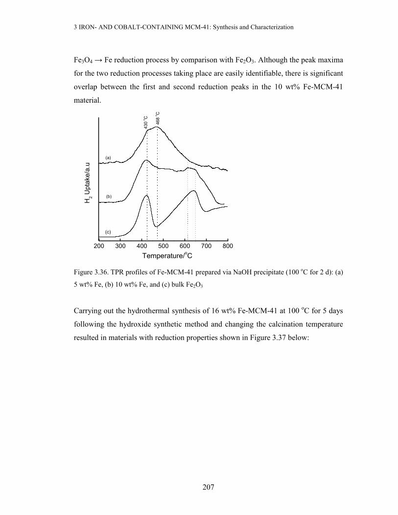
3 IRON- AND COBALT-CONTAINING MCM-41: Synthesis and Characterization
207
Fe3O4 → Fe reduction process by comparison with Fe2O3. Although the peak maxima
for the two reduction processes taking place are easily identifiable, there is significant
overlap between the first and second reduction peaks in the 10 wt% Fe-MCM-41
material.
200 300 400 500 600 700 800
H2 Uptake/a.u
(c)
Temperature/oC
(b)
(a)468 oC
430 oC
Figure 3.36. TPR profiles of Fe-MCM-41 prepared via NaOH precipitate (100 oC for 2 d): (a)
5 wt% Fe, (b) 10 wt% Fe, and (c) bulk Fe2O3
Carrying out the hydrothermal synthesis of 16 wt% Fe-MCM-41 at 100 oC for 5 days
following the hydroxide synthetic method and changing the calcination temperature
resulted in materials with reduction properties shown in Figure 3.37 below:

3 IRON- AND COBALT-CONTAINING MCM-41: Synthesis and Characterization
208
(a) (b)
Figure 3.37. TPR profiles of 16 wt% Fe-MCM-41 prepared via the OH- route at 100 oC for 5
days: (a) calcined at 450 oC for 12 h, and (b) calcined at 560 oC for 6 h.
Despite slight differences in the reduction temperatures for first reduction peak, the
two materials above show similar reduction features. They both undergo reduction to
Fe3O4 as shown by the broad feature invading the whole spectrum, and negligible
reduction to metallic Fe (a very small reduction feature at 647 oC). Note also that
materials prepared through this method are less reducible as compared to their
counterparts prepared by IWI method (which show at least two reduction peaks
characteristic of Fe2O3 reduction, see Figure 3.31).
The synthesis involving delayed addition of Fe3+(aq) to the synthesis gel was extended
to delayed addition of the Fe(OH)3 suspension (made from aqueous NaOH) to the
synthesis gel in order to prepare 16 wt% Fe-MCM-41. The TPR trace of the resulting
material after calcination at 560 oC for 6 h is shown in Figure 3.38.
200 400 600 800
20
40
60
80
100
120
641 oC
431 oC
H2 U
ptake/a.u
Temperature/oC
200 400 600 80020
40
60
80
100
120
647 oC
413 oC
H2 Uptake/a.u
Temperature/oC

3 IRON- AND COBALT-CONTAINING MCM-41: Synthesis and Characterization
209
200 300 400 500 600 700 800
H2 U
ptake/a.u
(b)
Temperature/oC
(a)
661 oC597 oC
492 oC
446 oC
Figure 3.38. The TPR profiles of (a) 16 wt% Fe-MCM-41 prepared by delayed addition of
Fe(OH)3 to the synthesis gel (100 oC for 2 days) and (b) bulk Fe2O3.
Apart from the presence of shoulders at ~492 oC and ~661 oC in the above reducto-
gram, this material shows two well-separated reduction peaks like bulk Fe2O3.
However, the peaks are shifted to higher reduction temperatures compared to those in
Fe2O3, probably due to strong interactions with the support. The presence of
shoulders on the high-temperature side of each peak may suggest the presence of iron
oxides in different environments. Therefore, not all the Fe present in this Fe-MCM-41
material is reducible to the metallic form.
Different precipitating agents have been compared in the synthesis of 16 wt% Fe-
MCM-41 by hydrothermal synthesis at 100 oC for 2 days. Figure 3.39 below shows
TPR traces of the 16 wt% Fe-MCM-41 made with Na2CO3 and triethanolamine
(abbreviated TEA or [HOCH2CH2]3N) after calcination at 560 oC for 6 h:

3 IRON- AND COBALT-CONTAINING MCM-41: Synthesis and Characterization
210
200 300 400 500 600 700 800
(b)
442 oC 489 oC
647 oC
H2 Uptake/a.u
Temperature/oC
(a)
416 oC
Figure 3.39. TPR profiles of 16 wt% Fe-MCM-41 prepared at 100 oC for 2 days via the OH-
precipitate route: (a) Na2CO3 and (b) (HOCH2CH2)3N as precipitant.
The material made from Na2CO3 as precipitant (Figure 3.39 (a)) for Fe(III) shows a
different reducibility behaviour from the TEA-derived material. It shows a single
broad reduction peak with a maximum at 416 oC with no reduction to Fe0, suggesting
that most of the Fe species are atomically dispersed in the mesoporous silica matrix.
On the other hand, the material made from triethanolamine as precipitant (Figure 3.39
(b)) shows two reduction peaks that are reminiscent of Fe2O3 reduction, and
undergoes reduction to metallic Fe (peak at 647 oC). Figure 3.39 (b) suggests that Fe
in this material is not in the silica matrix. The shoulder at 442 oC is within the
reduction range of Fe2O3, and may suggest the presence a different form of Fe2O3 in
the sample. The difference in the reduction behaviour of these two samples rationali-
zed by considering the XRD patterns of these two materials in the iron oxide region
(see XRD patterns in appendix A.4). No conspicuous metal oxide peaks are observed
in the XRD pattern of the material made with sodium carbonate as a precipitating
agent, whereas hematite-type peaks are observed in the XRD pattern of the TEA-
derived material. Also noteworthy is the high long-range order in the mesoporous
region of the carbonate-derived material as compared to the TEA-derived counterpart.
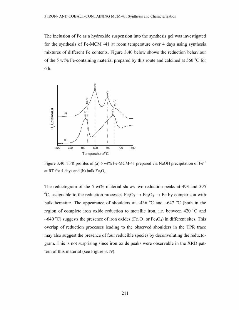
3 IRON- AND COBALT-CONTAINING MCM-41: Synthesis and Characterization
211
The inclusion of Fe as a hydroxide suspension into the synthesis gel was investigated
for the synthesis of Fe-MCM -41 at room temperature over 4 days using synthesis
mixtures of different Fe contents. Figure 3.40 below shows the reduction behaviour
of the 5 wt% Fe-containing material prepared by this route and calcined at 560 oC for
6 h.
200 300 400 500 600 700 800
H2 Uptake/a.u
(b)
(a) 640 oC
420 oC
Temperature/oC
436 oC
647 oC
595 oC
493 oC
Figure 3.40. TPR profiles of (a) 5 wt% Fe-MCM-41 prepared via NaOH precipitation of Fe3+
at RT for 4 days and (b) bulk Fe2O3.
The reductogram of the 5 wt% material shows two reduction peaks at 493 and 595 oC, assignable to the reduction processes Fe2O3 → Fe3O4 → Fe by comparison with
bulk hematite. The appearance of shoulders at ~436 oC and ~647 oC (both in the
region of complete iron oxide reduction to metallic iron, i.e. between 420 oC and
~640 oC) suggests the presence of iron oxides (Fe2O3 or Fe3O4) in different sites. This
overlap of reduction processes leading to the observed shoulders in the TPR trace
may also suggest the presence of four reducible species by deconvoluting the reducto-
gram. This is not surprising since iron oxide peaks were observable in the XRD pat-
tern of this material (see Figure 3.19).

3 IRON- AND COBALT-CONTAINING MCM-41: Synthesis and Characterization
212
3.3.3.2 TPR studies of Co-containing MCM-41
It is well-known that when Co compounds are heated in air, Co3O4 is formed [75]. In
this work, Co3O4 was prepared by heating the Co(OH)2 precipitate in air at 450 oC for
3 h. Figure 3.41 compares the TPR profile of this synthetic oxide with that reported
by Wu et al [75].
(a) (b)
Figure 3.41. TPR profiles of Co3O4: (a) synthesized in this work, (b) reported by Wu et al
[76].
Figure 3.41 shows the extensive similarity in reducibility between the cobalt oxide
prepared in this study and that reported elsewhere [76]. Other researchers have also
shown that the reductogram for reference Co3O4 consists of either a single reduction
peak or a two-step reduction process [77 - 81].
One of the methods used in this study to prepare Co-containing MCM-41 was
incipient wetness impregnation of siliceous MCM-41 with a solution of Co(II) nitrate
in 1 M HNO3, followed by drying and calcining at 560 oC for 6 h to give a material
with the cobalt loading of 16 wt%. The reducibility of the resulting material is shown
in Figure 3.42 below:
100 200 300 400 500
391 oC
303 oC
H2 U
ptake/a.u
Temperature/oC

3 IRON- AND COBALT-CONTAINING MCM-41: Synthesis and Characterization
213
200 300 400 500 600 700 800
(b)
H2 Uptake/a.u
Temperature/oC
(a)
716 oC393 oC
362 oC
326 oC
Figure 3.42. TPR profiles of (a) 16 wt% Co-MCM-41 prepared by IWI with a 1 M HNO3
solution of Fe3+ and calcined at 560 oC for 6 h, and (b) bulk Co3O4.
The 16 wt% Co-MCM-41 prepared by IWI shows two main reduction peaks at 326
and 362 oC (with a third shoulder-like peak at 393 oC). This suggests that the majority
of Co species is in the form of Co3O4 and follows the reduction sequence Co3O4 →
CoO → Co. The reduction peaks at 362 and 393 oC correspond to the reduction of
Co(II) in different interactive environments, i.e. a highly dispersed phase at 362 oC
and an agglomerated phase at 393 oC. The positions of the first two reduction peaks
are similar to those observed by Puskas et al [78] for Mg-promoted Co/SiO2 catalysts.
In addition, the high temperature reduction feature observed at 716 oC is associated
with a cobalt-silicate phase resulting from solid-state reactions where the cobalt ions
diffuse into the silica lattice [78].
Another method for synthesizing Co-MCM-41 materials was hydrothermal treatment
at 100 oC for 2 days, using freshly-precipitated Co(OH)2 slurry as a Co source. Figure
3.43 below shows TPR results of representative samples prepared via this route.

3 IRON- AND COBALT-CONTAINING MCM-41: Synthesis and Characterization
214
200 300 400 500 600 700 800
(c)
(b)H2 Uptake/a.u
391 oC
303 oC
Temperature/oC
388 oC
(a)
434 oC
362 oC
Figure 3.43. TPR profiles of Co-MCM-41 prepared via OH- precipitates at 100 oC for 2 days:
(a) 5 wt% Co, (b) 10 wt% Co and (c) bulk Co3O4. All Co-MCM-41 were calcined at 560 oC
for 6 h.
The broad character of the first reduction peaks at 362 and 388 oC for the Co-MCM-
41 materials in Figure 3.43 indicates that two reduction steps (Co3O4 → CoO → Co)
take place [81]. Since 5 wt% Co-MCM-41 starts to reduce at relatively lower
temperatures than its 10 wt% Co-MCM-41 counterpart (362 oC versus 388 oC), it can
be proposed that Co is more dispersed in the former material. The broad reduction
peaks at higher temperatures, increasing with Co content, suggest the presence of
strong metal-support interactions in Co-MCM-41.
For the 10 wt% Co-MCM-41 material described above, the extent of calcination has
also been found to influence the reducibility (see Figure 3.44 below).

3 IRON- AND COBALT-CONTAINING MCM-41: Synthesis and Characterization
215
200 300 400 500 600 700 800
(c)
391 o C
303 o C
Temperature/oC
(b)
(a)
H2 Uptake/a.u
388 o C
380 o C
Figure 3.44. TPR profiles of 10 wt% Co-MCM-41 prepared via the OH- route at 100 oC for 2
days: (a) calcined at 560 oC for 6 h, (b) calcined at 450 oC for 12 h and (c) bulk Co3O4.
The single reduction peak observed in 10 wt% Co-MCM-41 calcined at 450 oC is
sharper than that of the material calcined at 560 oC, and has a shoulder on the low
temperature side. This suggests the presence of two reduction steps taking place (Co3+
→ Co2+ → Co0), and is further supported by the broad peak at 388 oC in Figure 3.44
(a). The broad feature at higher reduction temperatures in the TPR profiles of Co-
MCM-41 are effects of SMSIs.
3.3.3.3 TPR studies of bimetallic-derivatized MCM-41
A bimetallic composite material of metal content (7.8 wt% Fe, 11.4 wt% Co-MCM-
41) was prepared by the HNO3-mediated incorporation of Fe(III) during hydrother-
mal synthesis (100 oC for 2 days). The reducibility of the resulting material after
calcination at 560 oC for 6 h is illustrated in Figure 3.45.

3 IRON- AND COBALT-CONTAINING MCM-41: Synthesis and Characterization
216
300 400 500 600 700 800
(b)
(a)
650 oC
420 oC
Temperature/oC
H2 U
ptake/a.u
574 oC
Figure 3.45. TPR profiles of (a) Fe2O3 and (b) (7.8 wt% Fe, 11.5 wt% Co)-MCM-41 prepared
at 100 oC for 2 days using a HNO3 solution of the metal precursors, and calcined at 560 oC
for 6 h.
The first reduction peak (Tred = 420 oC) and the last reduction peak (Tred = 650
oC) in
the bimetallic MCM-41 material (Figure 3.45 (b)) coincide with the reduction peaks
of bulk Fe2O3, and can be assigned accordingly. Since bulk Co3O4 is completely
reduced at T < 420 oC, the bimetallic peaks cannot be readily associated with cobalt
reduction, although the presence of shoulders may suggest the role of Co. The
reduction peak at 574 oC may suggest that the presence of Co has changed the
reduction pattern of Fe2O3 to follow the sequence Fe2O3 → Fe3O4 → FeO → Fe, i.e.,
Co facilitates reduction to Fe0, since no reduction to Fe0 was observed in the
monometallic Fe-MCM-41 analogue (Figure 3.35). Although further experimentation
may be necessary to identify the species giving rise to the shoulder at ~470 - 517 oC,
a guess may be that it is due to some form of cobalt ferrite.
Co-precipitation of Au(III) and Fe(III) from an aqueous solution of this mixture using
sodium silicate prior hydrothermal treatment at 100 oC for 5 days and eventual
calcination at 560 oC gave a material, nominal composition (1.9 wt% Au, 6.5 wt%
Fe)-MCM-41, with the reduction pattern shown in Figure 3.46:

3 IRON- AND COBALT-CONTAINING MCM-41: Synthesis and Characterization
217
200 400 600 800
30
40
50
60
70
427 oC
H2 U
ptake/a.u
Temperature/oC
Figure 3.46. TPR profile of (1.9 wt% Au, 6.5 wt% Fe)-MCM-41 prepared by coprecipition of
Au(III) and Fe(III) with water-glass prior to hydrothermal synthesis at 100 oC for 5 days,
calcined at 560 oC for 6 h.
The presence of one broad reduction peak centred at Tmax = 427 oC shows that only
the Fe2O3 → Fe3O4 reduction process takes place, with no further reduction to
metallic Fe. This may suggest that most of the Fe species is in strongly interacting
sites with the SiO2 or it is encapsulated. The influence of the Au component is not
obvious in this TPR profile, as Au is reduced by calcination (see also Figure 4.2).
3.3.4 Spectroscopic Methods
Further properties of Si-MCM-41, Fe-MCM-41 and Co-MCM-41 were briefly surve-
yed by ESR, Raman and Infrared spectroscopies.
3.3.4.1 Electron Spin Resonance Spectroscopy (ESR or EPR)
The Fe3+ ion in zeolitic environments is spherically symmetric due to the presence of
weak field ligands (H2O, OH- as well as O2-). It has an orbital singlet ground term

3 IRON- AND COBALT-CONTAINING MCM-41: Synthesis and Characterization
218
6A1g and no excited term of the same spin multiplicity. Thus reliable characterization
of Fe-MCM-41 cannot be obtained from UV-Vis spectra [46 and references cited
therein]. Therefore, ESR spectroscopy was used to elucidate the Fe environment in
Fe-MCM-41.
The room temperature X-band ESR spectra of Fe3+ isomorphously substituted in
MCM-41 through hydrothermal synthesis have been investigated as a function of cal-
cination temperature. Figure 3.47 below summarizes the observed changes in the co-
ordination environment of Fe in the resulting materials containing 5 wt% Fe:
1000 2000 3000 4000 5000 6000
(d)
Intensity/a.u
Magnetic Field/Gauss
(c)
(b)
g = 4.3
(a)
g = 4.3g = 2.3
g = 2.0
Figure 3.47. Room temperature X-band ESR spectra of 5 wt% Fe-MCM-41 prepared at 100 oC for 2 days as a function of calcination temperature: (a) as-synthesized, (b) 300 oC for 6 h,
(c) 400 oC for 6 h, and (d) 560 oC for 6 h.
It can be seen from the figure above that the coordination environment of Fe3+ is
dependent on the calcination temperature. The as-synthesized sample (Figure 3.47(a))
shows at least three signals corresponding to different environments, characterized by
different values of the Lande g-factor. The dominant Fe3+ environments are represe-
nted by ESR signals at g ≈ 4.3 and g ≈ 2.0, which are respectively assigned to Fe3+ in
tetrahedral framework sites and in octahedral (cation exchange or interstitial) sites
[82]. Similar observations have also been reported for MCM-41-derived materials

3 IRON- AND COBALT-CONTAINING MCM-41: Synthesis and Characterization
219
[26, 54]. Upon calcination at 300 oC for 6 h, the signal at g ≈ 4.3 decreased in
intensity and disappeared at even higher calcination temperatures, suggesting the
ejection of Fe3+ from framework sites during calcination. The increased linewidth of
the g ≈ 2.0 signal with calcination (∆Hpp = 555, 1241 and 1624 G for calcination
temperatures of 25, 300 and 400 oC, respectively) may suggest the migration of Fe3+
ions from framework to extraframework sites. Only a single signal with g ≈ 2.0 is
observed in materials that have been calcined at temperatures above 300 oC, confirm-
ing the presence of Fe in one type of coordination environment. Notably, the symme-
try and the size of this peak also shows some dependence on the calcination tempera-
ture. The breadth and higher g value for the material calcined at 400 oC (g ≈ 2.4) may
suggest the presence of iron oxyhydroxides [82]. In fact, the dislodgement of iron to
extraframework positions as a result of calcination has also been reported by Perez-
Ramirez et al [83] on the basis of techniques other than ESR.
The appearance of two types of coordination environments has also been observed for
the uncalcined 8.8 wt% Fe-MCM-41 material prepared at room temperature for 5
days via the nitric acid assisted addition of Fe3+ (Figure 3.48).
1000 2000 3000 4000 5000 6000
g = 2.0g = 4.3
Intensity/a.u
Magnetic Fielf/Gauss
Figure 3.48. ESR spectrum of as-synthesized 8.8 wt% Fe-MCM-41 prepared by room tempe-
rature synthesis for 5 days with a HNO3 solution of Fe(III).

3 IRON- AND COBALT-CONTAINING MCM-41: Synthesis and Characterization
220
The relative peak sizes in this figure suggests that there is relatively little Fe in the
framework (g ≈ 4.3) compared to extraframework Fe species (g ≈ 2.0).
The use of maleic acid in stead of HNO3 to synthesize 8.8 wt% Fe-MCM-41 under
hydrothermal conditions produced a material with an ESR spectrum shown in Figure
3.49.
1000 2000 3000 4000 5000 6000
g = 2.3
g = 2.0
Intensity/a.u
Magnetic Field/Gauss
Figure 3.49. ESR spectrum of 8.8 wt% Fe-MCM-41 prepared at 100 oC for 2 days using
Fe(III) in maleic acid solution, followed by calcination at 560 oC for 6 h.
The material shows ESR features reminiscent of its analogue prepared using nitric
acid solution for the introduction of Fe(III). The majority is in the extraframework
sites as clusters (g values of 2.0 and 2.3). Notably, the g = 2.0 peak in this material is
narrower (248 G) than that of the corresponding material prepared with nitric acid
(1033 G). The peak at g = 2.3 has been assigned to randomly oriented Fe(III) in
hydrated oxide species [47, 48].
Using an oxalic acid solution of Fe(III) in the room temperature synthesis of 8.8 wt%
Fe-MCM-41 over 5 days produced a material with the ESR spectrum in Figure 3.50
(next page). The spectrum shows that calcined Fe-MCM-41 consists of Fe species
exclusively in extraframework sites (g = 2.0), and only a negligible amount of Fe

3 IRON- AND COBALT-CONTAINING MCM-41: Synthesis and Characterization
221
exists as framework species (g = 4.3). The g = 2.0 signal has a linewidth (given as a
peak-to-peak derivative distance) of ∆Hpp ≈ 954 G.
1000 2000 3000 4000 5000 6000
g = 4.3
g = 2.0
Intensity/a.u
Magnetic Field/Gauss
Figure 3.50. ESR spectrum of calcined (560 oC for 6 h) 8.8 wt% Fe-MCM-41 prepared at RT
for 5 days with Fe(III) in oxalic acid solution,
The Fe-containing material prepared by incipient wetness impregnation with a 1 M
HNO3 solution of Fe(III) also showed features exhibited by materials made by direct
synthesis. Figure 3.51 (next page) shows the ESR spectrum of calcined 16 wt% Fe-
MCM-41 prepared by IWI. As can be expected, there is very little Fe species going
into framework sites, because use is made of an already ordered support which is
difficult to penetrate by impregnation. Most of the Fe is extraframework as can be
seen by the size of the signal with g = 2.0, with ∆Hpp = 1433 G.

3 IRON- AND COBALT-CONTAINING MCM-41: Synthesis and Characterization
222
1000 2000 3000 4000 5000 6000
g = 2.0
g = 4.2
Intensity/a.u
Magnetic Field/Gauss
Figure 3.51. The ESR spectrum of 16 wt% Fe-MCM-41 prepared by IWI with a 1 M HNO3
solution of Fe(III), and calcined at 560 oC for 6 h.
Despite its relatively larger size compared to Fe(III), Ru(III) has been observed in
both framework (g = 4.0) and extraframework (g = 2.2) in Ru-MCM-41 prepared by
direct hydrothermal synthesis via the NaOH precipitate route (Figure 3.52, next
page).
1000 2000 3000 4000 5000 6000
g = 4.2
g = 2.2
Intensity/a.u
Magnetic Field/Gauss
Figure 3.52. ESR spectrum of 16 wt% Ru-MCM-41 prepared at 100 oC for 2 days using the
OH- synthesis route, and calcined at 560 oC for 6 h.

3 IRON- AND COBALT-CONTAINING MCM-41: Synthesis and Characterization
223
On the other hand, the Co2+ (d7) ions can exist in high-spin (S = 3/2) or low-spin (S =
½) states, and has a nuclear spin I = 7/2. Due to the weak ligand character of the
framework oxygens in zeolitic environments [84], the high-spin S = 3/2 state can be
assumed. The sensitivity of this quartet state to the environment makes it useful in
probing the coordination structure [85] of Co2+, although spin-lattice relaxation often
precludes the observation of the associated ESR signals, especially those of
octahedral symmetry [86]. In the tetrahedrally-coordinated high-spin cobalt
environments, the 4A2 ground state (zero field splitting, ZFS) will split into two
doublets with ms = ±3/2 and ±1/2 [87], and the sign of ZFS determines whether ms =
±3/2 or ±1/2 lies lower in energy. The corresponding g values are determined by three
allowed ∆ms = ±1 transitions. The mixing of the Zeeman and ZFS splittings gives rise
to a large anisotropy of the effective g-values, and the ESR signals are usually
observed only at temperatures below 77 K.
As in the case of Fe3+ and Ru3+, the introduction of Co2+ into the MCM-41 can result
in cobalt either occupying framework positions or cation exchange sites. These sites
can be distinguished by ESR spectroscopy outlined above. Figure 3.53 illustrates
structural changes of the 16 wt% Co-MCM-41 materials prepared using the IWI
method. These materials show ESR features (g-values) normally encountered in met-
allosilicates. The uncalcined material (Figure 3.53 (a)) show an additional small peak
with g = 4.0 characteristic of framework metal species, whereas upon calcination
(Figure 3.53(b)) only the signal with g = 2.0 is observed and characterizes extra-
framework metal species.

3 IRON- AND COBALT-CONTAINING MCM-41: Synthesis and Characterization
224
1000 2000 3000 4000 5000 6000
(b)
Intensity/a.u
Magnetic Field/Gauss
(a)
g = 4.0
g = 2.0g = 3.8
g = 3.5
Figure 3.53. ESR spectra of 16 wt% Co-MCM-41 prepared by IWI with HNO3 solution of
Co(II): (a) dried overnight at 110 oC, and (b) calcined at 560 oC for 6 h.
The one-pot synthesis of the 16 wt% Co-MCM-41 via the OH- route at 100 oC and
room temperature, produced materials with the ESR spectra in Figure 3.54 (next
page).
(a) (b)
Figure 3.54. ESR spectra of 16 wt% Co-MCM-41 prepared by one-pot synthesis via the OH-
route under different conditions: (a) 100 oC for 48 h, calcined at 560 oC for 6 h, (b) RT
synthesis for 5 days, uncalcined.
1000 2000 3000 4000 5000 6000
g = 2.1
g = 2.8
g = 3.8
Intensity/a.u
Magnetic Field/Gauss
1000 2000 3000 4000 5000 6000
g = 1.79
g = 5.3
Intensity/a.u
Magnetic Field/Gauss
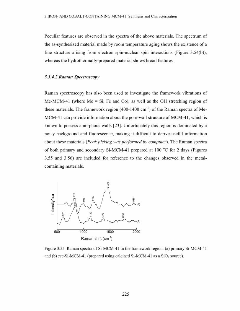
3 IRON- AND COBALT-CONTAINING MCM-41: Synthesis and Characterization
225
Peculiar features are observed in the spectra of the above materials. The spectrum of
the as-synthesized material made by room temperature aging shows the existence of a
fine structure arising from electron spin-nuclear spin interactions (Figure 3.54(b)),
whereas the hydrothermally-prepared material shows broad features.
3.3.4.2 Raman Spectroscopy
Raman spectroscopy has also been used to investigate the framework vibrations of
Me-MCM-41 (where Me = Si, Fe and Co), as well as the OH stretching region of
these materials. The framework region (400-1400 cm-1) of the Raman spectra of Me-
MCM-41 can provide information about the pore-wall structure of MCM-41, which is
known to possess amorphous walls [23]. Unfortunately this region is dominated by a
noisy background and fluorescence, making it difficult to derive useful information
about these materials (Peak picking was performed by computer). The Raman spectra
of both primary and secondary Si-MCM-41 prepared at 100 oC for 2 days (Figures
3.55 and 3.56) are included for reference to the changes observed in the metal-
containing materials.
500 1000 1500 2000
1752
1139
1373
1946
1169
995
620
850
Raman shift (cm-1)
825
(b)
(a)
1469
Intensity/a.u
Figure 3.55. Raman spectra of Si-MCM-41 in the framework region: (a) primary Si-MCM-41
and (b) sec-Si-MCM-41 (prepared using calcined Si-MCM-41 as a SiO2 source).
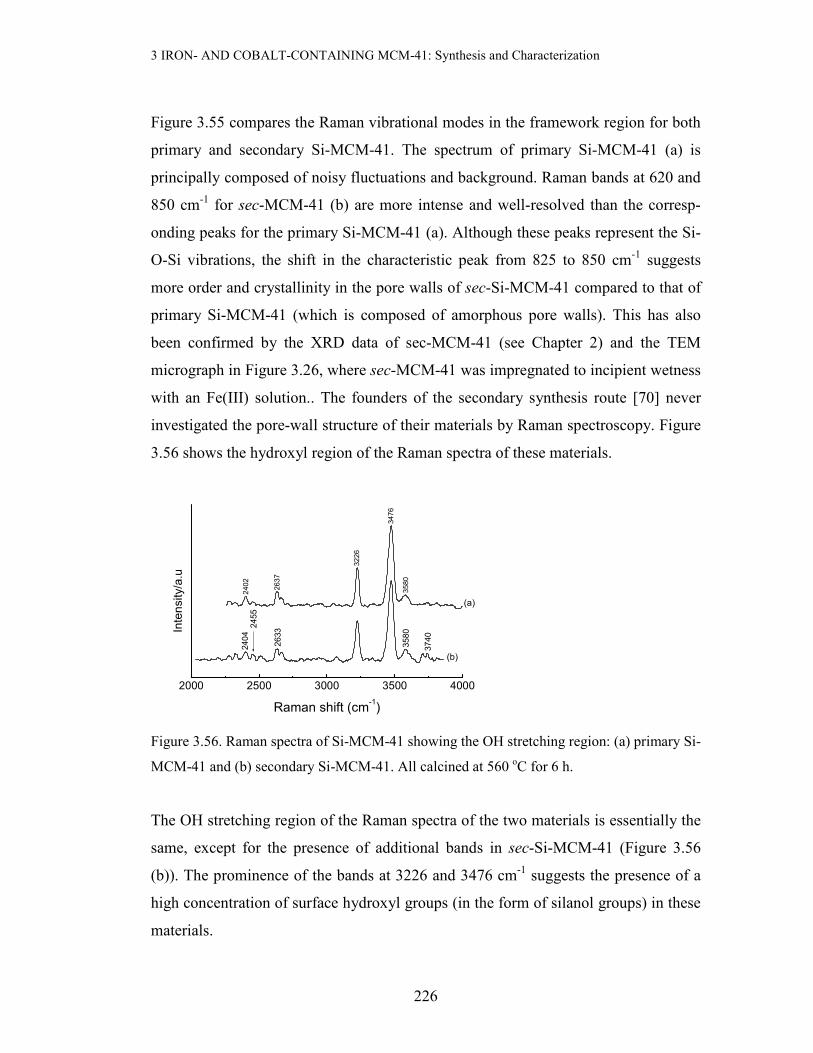
3 IRON- AND COBALT-CONTAINING MCM-41: Synthesis and Characterization
226
Figure 3.55 compares the Raman vibrational modes in the framework region for both
primary and secondary Si-MCM-41. The spectrum of primary Si-MCM-41 (a) is
principally composed of noisy fluctuations and background. Raman bands at 620 and
850 cm-1 for sec-MCM-41 (b) are more intense and well-resolved than the corresp-
onding peaks for the primary Si-MCM-41 (a). Although these peaks represent the Si-
O-Si vibrations, the shift in the characteristic peak from 825 to 850 cm-1 suggests
more order and crystallinity in the pore walls of sec-Si-MCM-41 compared to that of
primary Si-MCM-41 (which is composed of amorphous pore walls). This has also
been confirmed by the XRD data of sec-MCM-41 (see Chapter 2) and the TEM
micrograph in Figure 3.26, where sec-MCM-41 was impregnated to incipient wetness
with an Fe(III) solution.. The founders of the secondary synthesis route [70] never
investigated the pore-wall structure of their materials by Raman spectroscopy. Figure
3.56 shows the hydroxyl region of the Raman spectra of these materials.
2000 2500 3000 3500 4000
2455
2633
2404
3740
3580
(a)
(b)
Raman shift (cm-1)
Intensity/a.u
3476
2402
2637
3226
3580
Figure 3.56. Raman spectra of Si-MCM-41 showing the OH stretching region: (a) primary Si-
MCM-41 and (b) secondary Si-MCM-41. All calcined at 560 oC for 6 h.
The OH stretching region of the Raman spectra of the two materials is essentially the
same, except for the presence of additional bands in sec-Si-MCM-41 (Figure 3.56
(b)). The prominence of the bands at 3226 and 3476 cm-1 suggests the presence of a
high concentration of surface hydroxyl groups (in the form of silanol groups) in these
materials.
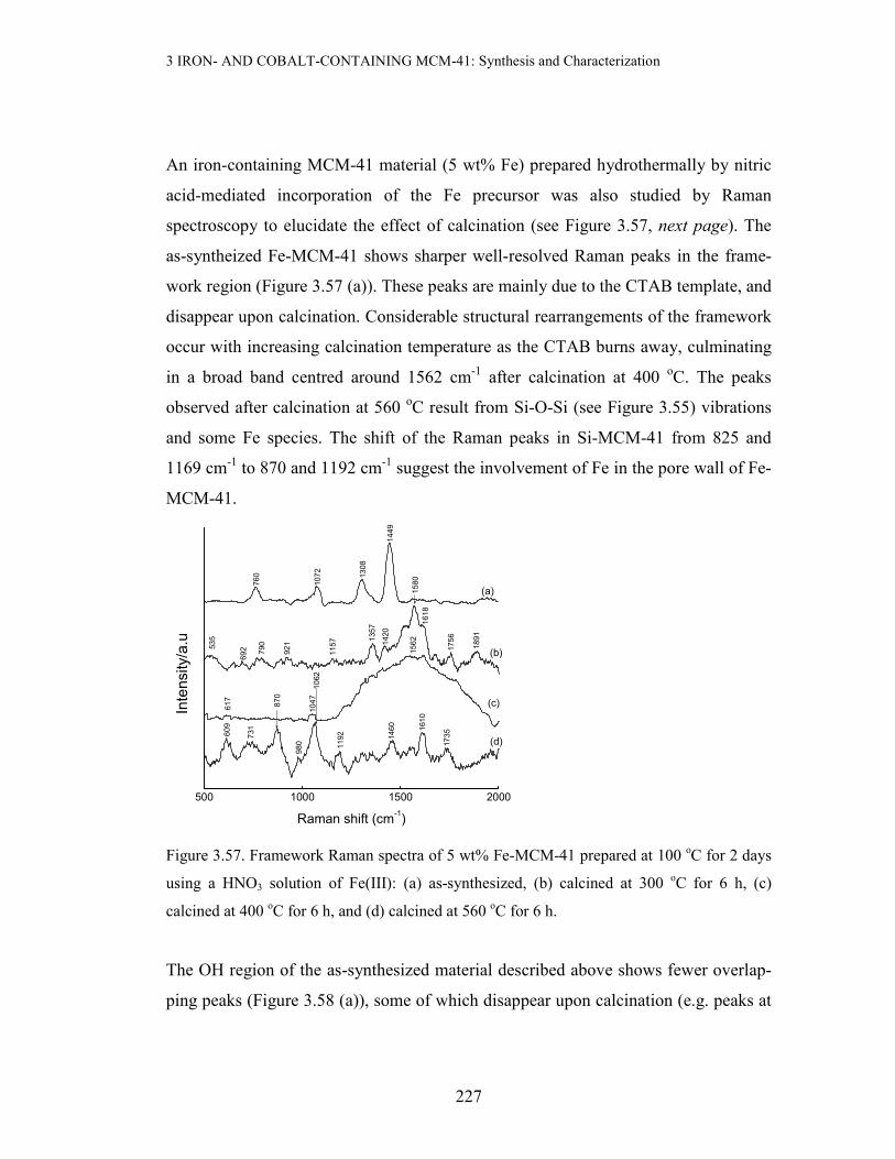
3 IRON- AND COBALT-CONTAINING MCM-41: Synthesis and Characterization
227
An iron-containing MCM-41 material (5 wt% Fe) prepared hydrothermally by nitric
acid-mediated incorporation of the Fe precursor was also studied by Raman
spectroscopy to elucidate the effect of calcination (see Figure 3.57, next page). The
as-syntheized Fe-MCM-41 shows sharper well-resolved Raman peaks in the frame-
work region (Figure 3.57 (a)). These peaks are mainly due to the CTAB template, and
disappear upon calcination. Considerable structural rearrangements of the framework
occur with increasing calcination temperature as the CTAB burns away, culminating
in a broad band centred around 1562 cm-1 after calcination at 400 oC. The peaks
observed after calcination at 560 oC result from Si-O-Si (see Figure 3.55) vibrations
and some Fe species. The shift of the Raman peaks in Si-MCM-41 from 825 and
1169 cm-1 to 870 and 1192 cm-1 suggest the involvement of Fe in the pore wall of Fe-
MCM-41.
500 1000 1500 2000
Intensity/a.u
(d)
1460
17351610
1192
980
870
Raman shift (cm-1)
1562
1157
535
(c)
(b)
731
692 790
921
1062
609
617
1047
1891
1756
1420
1357
(a)
1618
1580
760
1072
1308
1449
Figure 3.57. Framework Raman spectra of 5 wt% Fe-MCM-41 prepared at 100 oC for 2 days
using a HNO3 solution of Fe(III): (a) as-synthesized, (b) calcined at 300 oC for 6 h, (c)
calcined at 400 oC for 6 h, and (d) calcined at 560 oC for 6 h.
The OH region of the as-synthesized material described above shows fewer overlap-
ping peaks (Figure 3.58 (a)), some of which disappear upon calcination (e.g. peaks at

3 IRON- AND COBALT-CONTAINING MCM-41: Synthesis and Characterization
228
2850, 2893 and 3038 cm-1) and suggest their origin to be either a volatile or combus-
tible species. Indeed, the peaks at about 3000 cm-1 in Figure 3.58 (a) corres-pond to
the C-H stretching vibrations [88], arising from the surfactant template that is still oc-
cluded in the as-synthesized material. Peaks can be seen at about 3226 and 3476 (due
to the high concentration of surface hydroxyl groups) and these peaks become more
prominent upon calcination. The position of these two peaks remained remark-ably
constant throughout the calcination range (up to 750 oC) and are diagnostic of these
materials.
2000 2500 3000 3500 4000
(c)
2480
2462
2403
2630
560 oC
Raman shift (cm-1)
(b)
(a)
Intensity/a.u
2649
400 oC
2726
2890
3038
3226
3476
As-synthesized
Figure 3.58. Raman spectra of 5 wt% Fe-MCM-41 (2 days at 100 oC) in the OH region: (a)
as-synthesized, (b) calcined at 400 oC for 6 h, and (c) calcined at 560 oC for 6 h.
A qualitative ranking of the amount of OH groups was obtained by fitting the Voigt
function to the most intense peak (3476 cm-1), and determining the area under this
peak. The area was taken as a qualitative measure of the concentration of OH groups
(see Figure 3.59).

3 IRON- AND COBALT-CONTAINING MCM-41: Synthesis and Characterization
229
3400 3450 3500 3550 3600
Intensity/a.u
5.5 wt% Fe-M41 (1978 Voigt units)
9 wt% Fe-M41 (1319 Voigt units)
Raman Shift (cm-1)
2 wt% Fe-M41 (2902 Voigt units)
Si-M41 (3103 Voigt units)
3476
Figure 3.59. The Raman spectra of Fe-containing MCM-41 prepared at 100 oC for 2 days
using HNO3 for iron incorporation. All samples were calcined at 560 oC for 6 h. In brackets is
given the Voigt area of the OH peak. M41 represents MCM-41.
Figure 3.59 and the attached data show that the presence of Fe reduces the area of the
OH peak in Fe-MCM-41 relative to the pure silica material. The decrease in OH peak
area with increasing Fe content arises from the reaction of surface silanol groups with
iron complexes during preparation, leading to lower concentrations of terminal OH
groups.
The revelation by XRD studies that the 16 wt% Fe-MCM-41 material prepared using
primary Si-MCM-41 as a silica source gave materials with excellent mesoporosity
(Tables 3.3 and 3.4), coupled with the better reducibility properties of the Fe species
in this material (see Figure 3.34) prompted a Raman spectroscopic study of these
materials. Materials prepared via this route from aqueous Fe(III) solutions were
calcined at 560 oC for 3 h and 6 h, and their Raman spectra were recorded (Figure
3.60).

3 IRON- AND COBALT-CONTAINING MCM-41: Synthesis and Characterization
230
500 750 1000 1250 1500 1750 2000
(c)1168
Intensity/a.u
Raman shift (cm-1)
(b)
1570
1786
1735
617
702
1165
1254
1793
(a)
1728
1618
1380
1352
1133
1073
886
705
615
850
Figure 3.60. Framework Raman spectra of 16 wt% Fe-MCM-41 prepared with Si-MCM-41
as a SiO2 source (100 oC for 2 days) and calcined at 560 oC: (a) sec-Si-MCM-41 reference
sample, (b) calcined for 3 h and (c) calcined for 6 h.
The Raman structural changes in the 16 wt% Fe-MCM-41 prepared using calcined
Si-MCM-41 as a SiO2 source have been referenced to secondary Si-MCM-41 (Figure
3.60). The OH region of the Raman spectra of these Fe-MCM-41 materials has been
omitted as it showed essentially the same features as Si-MCM-41. However, the
framework region does show some changes (Figure 3.60 (b) and (c)), possibly
associated with the pore wall structure. A new peak appears at ~700 cm-1 in the
Raman spectra of Fe-MCM-41, and its absence in Si-MCM-41 suggests that it
originates from an iron-silicate species. This peak becomes sharper and more
resolved upon increasing the calcination time to 6 h (Figure 3.60 (c)). The peak at 850
cm-1 in the spectrum of Si-MCM-41 has shifted by 36 cm-1 to higher frequencies in
the Fe-containing materials, and is also became sharper. This blue-shifting and
sharpening suggests that the pore wall of the Fe-containing sample is stronger and
more crystalline than that of sec-Si-MCM-41. Also, the most intense and sharpest
peak at about 1352 cm-1 after 6 h calcination can also be associated with the presence
of Fe in the silica matrix, as only a feeble peak is observed at 1380 cm-1 in the
reference material. This shift (28 cm-1) to lower vibrational frequencies suggests the
presence of Fe in the framework positions since the harmonic oscillator (Fe-O-Si) in

3 IRON- AND COBALT-CONTAINING MCM-41: Synthesis and Characterization
231
Fe-MCM-41 has a higher reduced mass than the corresponding Si-O-Si oscillator in
Si-MCM-41 [26]. Therefore, the confluence of the presence of Fe and the secondary
synthesis produces a product with strengthened pore wall morphology.
The Raman spectra of a 16 wt% Fe-MCM-41 material, synthesized by hydrothermal
treatment at 100 oC for 48 h using tetramethylammonium hydroxide (TMAOH) as a
precipitant, were recorded in the OH region (Figure 3.61).
2000 2500 3000 3500 4000
2633
2400
Intensity/a.u
2626
3224
(b)
(a)
Raman shift (cm-1)
34742897
Figure 3.61. Raman spectra of 16 wt% Fe-MCM-41 prepared by the TMAOH precipitate
route: (a) as-synthesized and (b) calcined at 560 oC for 6 h.
A broad Raman band at ~2897 cm-1 in Figure 3.61 (a) is associated with the occluded
template, and it disappears after calcination. Characteristically, the OH stretching
region always shows two sharp and intense Raman peaks at 3225 and 3475 cm-1
associated with the surface silanol groups. These peaks also appear in the Raman
spectrum of Si-MCM-41.
Cobalt-containing MCM-41 derivatives have also been studied by Raman spectrosc-
opy. Figure 3.62 shows the Raman spectra of a 16 wt% Co-MCM-41 materials prepa-
red by two different methods (IWI and one-pot synthesis via the OH- route).

3 IRON- AND COBALT-CONTAINING MCM-41: Synthesis and Characterization
232
(a) (b)
Figure 3.62. Comparative Raman spectra of 16 wt% Co-MCM-41 prepared by IWI from
nitric acid solution and hydrothermally via the Co(OH)2 route: (a) Framework region and (b)
OH region. All samples were calcined at 560 oC for 6 h.
The OH stretching region of the Co-containing MCM-41 materials does not show
sensitivity to the preparation method, and like Si-MCM-41, shows the presence of a
high concentration of hydroxyl groups. Despite the low signal-to-noise ratio in the
framework region of the spectra above (Figure 3.62 (a)), the most intense peak at
~693 cm-1 can be observed in both Co-MCM-41 materials. This peak appeared at
~670 cm-1 in the Raman spectrum of primary Si-MCM-41 (Figure 3.55 (a)), and the
observed 20 cm-1 shift to higher frequencies in Co-MCM-41 can be associated with
pore-wall strengthening. Also, the peak at ~1469 cm-1 in the Raman spectrum of
primary Si-MCM-41 has shifted to 1397 and 1374 cm-1 in the spectra of Co-MCM-41
prepared by one-pot and IWI methods, respectively. These shifts to lower frequencies
suggests incorporation of Co into the framework, and can be associated with the
vibration of the Co-O-Si rotor, which has a higher reduced mass than Si-O-Si.
2000 2500 3000 3500 4000
IWI
Raman shift (cm-1)
3575
2406
2631
3224
3476
Intensity/a.u
OH- route
500 1000 1500 2000
1800
1638
885 1193
1374
Intensity/a.u
(b) IWI
Raman shift (cm-1)
542
13971197
948
853
693
(a) OH- route
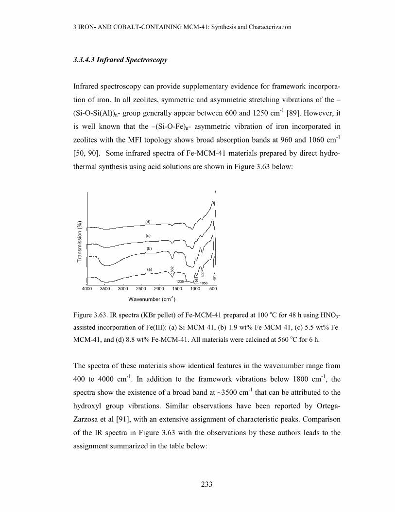
3 IRON- AND COBALT-CONTAINING MCM-41: Synthesis and Characterization
233
3.3.4.3 Infrared Spectroscopy
Infrared spectroscopy can provide supplementary evidence for framework incorpora-
tion of iron. In all zeolites, symmetric and asymmetric stretching vibrations of the –
(Si-O-Si(Al))n- group generally appear between 600 and 1250 cm-1 [89]. However, it
is well known that the –(Si-O-Fe)n- asymmetric vibration of iron incorporated in
zeolites with the MFI topology shows broad absorption bands at 960 and 1060 cm-1
[50, 90]. Some infrared spectra of Fe-MCM-41 materials prepared by direct hydro-
thermal synthesis using acid solutions are shown in Figure 3.63 below:
4000 3500 3000 2500 2000 1500 1000 500
(b)
(a)
Transmission (%)
1632
1235 1056
961 800
461
Wavenumber (cm-1)
(c)
(d)
Figure 3.63. IR spectra (KBr pellet) of Fe-MCM-41 prepared at 100 oC for 48 h using HNO3-
assisted incorporation of Fe(III): (a) Si-MCM-41, (b) 1.9 wt% Fe-MCM-41, (c) 5.5 wt% Fe-
MCM-41, and (d) 8.8 wt% Fe-MCM-41. All materials were calcined at 560 oC for 6 h.
The spectra of these materials show identical features in the wavenumber range from
400 to 4000 cm-1. In addition to the framework vibrations below 1800 cm-1, the
spectra show the existence of a broad band at ~3500 cm-1 that can be attributed to the
hydroxyl group vibrations. Similar observations have been reported by Ortega-
Zarzosa et al [91], with an extensive assignment of characteristic peaks. Comparison
of the IR spectra in Figure 3.63 with the observations by these authors leads to the
assignment summarized in the table below:

3 IRON- AND COBALT-CONTAINING MCM-41: Synthesis and Characterization
234
Table 3.16. Assignment of IR vibrational peaks in Fe-containing MCM-41 materials
in Figure 3.63.
Peak position /cm-1 Assignment
461 Si-O-Si rocking vibration
800 Si-O-Si bending vibration
961 Si-[OH] group vibrationa
1056 Si-O-Si asymmetrical stretch vibration
1235 Internal asymmetric Si-O-Si stretch
1632 Deformation mode of molecular H2O
aAlso reported by A. Duran, C. Serna, et al [92]
Note that the sample with the most intense water peak also has the broadest hydroxyl
peak, presumably as a result of polarized water in the material. The constancy of the
peak positions arises because the materials have been subjected to the same extent of
calcination, leading to the ejection of the Fe from the framework positions [26]. Thus,
the observed vibrations are essentially due to Si-O-Si linkages, with little or no
contributions from Si-O-Fe vibrations.
3 IRON- AND COBALT-CONTAINING MCM-41: Synthesis and Characterization
235
3.4. Conclusions
Metal-containing MCM-41 materials have been successfully synthesized using differ-
rent methods, including a one-pot synthesis and incipient wetness impregnation. The
one-pot synthesis offered the option of carrying out the synthesis at different tempera-
tures. Synthesis parameters were optimized using different synthesis temperature con-
ditions. Among these characterization techniques, XRD, BET, and TEM, provided
conclusive evidence regarding the quality of the product Me-MCM-41 (Me = Fe and
Co). The XRD patterns and BET surface area measurements also revealed the reten-
tion of the mesostructure of the metal-derivatized materials, although partial collapse
was observed with increased metal content of the synthesis gel. Transition metal
incorporation beyond ~ 9 wt% by the one-pot synthesis gave rise to metallosilicates
with a reduced mesoporous character as evidenced by the reduced (100) XRD peak,
and the disappearance of the higher order peaks in the XRD patterns of the final
materials (i.e., partial loss of structure became evident at these loadings). This was
also found to be the case in the acid-assisted addition of transition metal precursors.
Interestingly, the use of Si-MCM-41 as a SiO2 source and aqueous Fe(III) in the
hydrothermal synthesis of 16 wt% Fe-MCM-41 produced a nanocomposite material
with maximum retention of the XRD mesoporosity (see Tables 3.3 and 3.4). Also, the
identity of the acid used to aid Fe(III) incorporation in the preparation of 8.8 wt% Fe-
MCM-41 was found to affect the mesoporosity of the product as follows: (i) ao trend,
tartaric ~ maleic < oxalic < EDTA < nitric, and (ii) SBET trend, tartaric < EDTA <
water < oxalic < nitric. These two trends made HNO3 and acid of choice in
synthesizing Fe-containing nanocomposites with loadings of ≤ 8.8 wt % Fe. Studies
on 5 wt% Fe-MCM-41 prepared by this route have revealed that the variation of the
XRD data (lattice parameters) for the as-synthesized material with calcination tempe-
rature can be used to estimate the optimum calcination temperature, similar to the use
of TGA (see Figure 3.12).

3 IRON- AND COBALT-CONTAINING MCM-41: Synthesis and Characterization
236
The base-assisted metal incorporation was found to yield materials with excellent
XRD mesoporous properties, with 3-4 low-angle peaks observable in their XRD
patterns. For materials with high metal content (> 8 wt%) in this base-assisted
approach, metal oxide peaks could also be observed at high 2θ values. This suggests
that at these loadings, the limit of metal loading has been exceeded, and that clusters
have started forming in detectable amounts. As opposed to the other precipitating
agents used to incorporate Fe(III) during direct hydrothermal synthesis of a 16 wt%
Fe derivative, Na2CO3 gave rise to a material with excellent XRD mesoporosity and
no obvious metal oxide peaks at this loading. The origin of this finding is not clear at
present. The lattice parameters of the materials prepared by this route were insensitive
to the synthesis time (2 to 5 days at 100 oC). On the other hand, the incipient wetness
impregnation method gave rise to transition metal-containing mesporous materials
with preserved mesoporosity, showing all four low-angle reflection peaks regardless
of the metal loading. In the case of Fe-MCM-41 materials prepared by IWI, up to 50
wt% Fe could be loaded without significantly affecting the XRD mesoporosity (see
Figure 3.5). However, no obvious metal oxide peaks were observed for the 5 wt% Fe-
MCM-41 material prepared through IWI of sec-Si-MCM-41, suggesting a good dis-
persion at this loading in the context of XRD (Figure 3.4). Similar trends were obser-
ved for the Co-MCM-41 materials.
Regardless of the method of preparation, all metal-containing MCM-41 derivatives
reported in this study had exceptionally high BET surface areas (222 – 1226 m2/g).
However, the surface areas were found to decrease as the metal content of the metal-
losilicate was increased. For the same metal content, the Co-MCM-41 materials gave
superior BET surface areas compared to their Fe-MCM-41 counterparts. This has
been attributed to the ease of incorporating the Co(II) into the framework as opposed
to incorporating Fe(III), because of the smaller effective nuclear charge in the latter.
Also noteworthy is the fact that for the same metal and same loading, materials prep-
ared at room temperature have higher surface areas than those obtained hydrotherm-
ally.
3 IRON- AND COBALT-CONTAINING MCM-41: Synthesis and Characterization
237
XRD and BET measurements have shown that the degree of mesoporous framework
destruction during the one-pot hydrothermal incorporation of transition metal ions
increases in the order Co < Fe < Ru, i.e. in order of increasing size.
All materials made with water-glass as a silica source showed a high order in their
hexagonal pore arrangements. Low loadings (≤ 3 wt% Fe) showed HRTEM micro-
graphs almost similar to siliceous MCM-41, with no observable iron oxide particles
in the image. However, even in materials where HRTEM could not detect the Fe
oxide clusters, EDS could confirm the presence of Fe. For higher Fe loadings,
HRTEM results have demonstrated that a greater part of the pore system remained
intact, even though some loss of long-range order was evident. Fe clusters could also
be observed on the surface of the support. Aerosol synthesis and other TEOS-based
syntheses of Fe-MCM-41 resulted in materials with no pore ordering, although
surface areas as high as 1024 m2/g could be obtained. HRTEM has also shown the
preservation of long-range order in the Fe-containing materials prepared by IWI, in
addition to pore thickening in the material prepared on secondary Si-MCM-41 as a
support.
From TPR studies, it was noted that the reducibility of Me-MCM-41 (Me = Co or Fe)
prepared by incipient wetness impregnation is excellent and reminiscent of bulk metal
oxide reduction, as opposed to the one-pot-synthesized samples where metal-support
interactions or even encapsulation of the metal by the support is dominant. By
analogy with Fe2O3, the two reduction peaks in Fe-MCM-41 could be assigned to the
processes Fe2O3 → Fe3O4 → Fe, while those in Co-MCM-41 could be assigned to the
process Co3O4 → CoO → Co. With few exceptions, the one-pot synthesized
materials were shown to give a single broad reduction feature, suggesting that the
metal oxide species in these materials are difficult to reduce. Most of the samples
prepared by the one-pot synthesis method showed no reduction to metallic Fe or Co.
However, the one-pot hydrothermal synthesis in which pre-formed Si-MCM-41 was
used as a SiO2 source showed three reduction peaks (see Figure 3.34) in the

3 IRON- AND COBALT-CONTAINING MCM-41: Synthesis and Characterization
238
temperature range where Fe2O3 is reduced to metallic Fe. Another important
observation in this study was that unlike other Fe-MCM-41 materials prepared by the
base precipitate route, the 16 wt% Fe-MCM-41 in which Fe(III) was precipitated with
triethanolamine prior to hydrothermal synthesis (Figure 3.39), showed two distinct
reduction peaks in it TPR spectrum and suggested reduction to metallic Fe. The
single broad reduction peak observed in the 16 wt% Fe-MCM-41 prepared by the
Na2CO3 precipitation route (also Figure 3.39) tallies with the XRD observation,
where no obvious metal oxide peaks are observed (see appendix A.4). It can thus be
concluded that the Na2CO3 precipitate synthesis route produces a highly dispersed Fe
phase through the silica matrix. Also, Co-MCM-41 materials are more easily reduc-
ible than their Fe-MCM-41 counterparts, regardless of the method of preparation.
The presence of Co in (7.8 % Fe, 11.4 % Co)-MCM-41 prepared by the nitric acid
route seemed to promote or catalyze the reduction of Fe3+ to Fe0, which was not
observed in its monometallic Fe analogue (see Figures 3.35 and 3.45). The mono-
metallic Fe analogue showed a one-peak reduction profile to Fe3O4, while the bi-
metallic composite material showed a three-peak reduction pattern in its TPR profile.
In general, XRD and TPR results have pointed to the presence of Fe as Fe2O3 and Co
as Co3O4 in prepared Fe- and Co-MCM-41, respectively.
ESR spectroscopic studies revealed that the Fe in the as-synthesized Fe-MCM-41
matrix can occupy both framework (g ≈ 4.3) and extraframework sites (g ≈ 2.0), and
that the occupancy is highly temperature-dependent. There is dislodgement of a signi-
ficant fraction of Fe from framework to extraframework sites upon calcining the mat-
erials above 400 oC. The framework Raman spectra of the surfactant-containing mat-
erials could not supplement ESR observations, because of the dominance and pos-
sible overlaps of the template C-C and C-H vibrations with those arising from frame-
work vibrations. The calcined metal-containing materials showed enhanced well-
resolved peaks in the framework region as compared to the siliceous material. This

3 IRON- AND COBALT-CONTAINING MCM-41: Synthesis and Characterization
239
observation suggests that the presence of heteroatoms reinforces and strengthens the
pore walls of the resulting materials, because Si-MCM-41 is dominated by amorp-
hous pore walls. This is also evidenced by secondary Si-MCM-41, which has more
highly ordered pores than primary Si-MCM-41. The confluence of secondary synthe-
sis and the presence of Fe is apparent in the Raman spectrum of the 16 wt% Fe-
MCM-41 prepared using calcined Si-MCM-41 as a SiO2 source (Figure 3.60), which
suggests extended pore-wall strengthening. However, in a few samples, the Raman
spectra in this region could show a shift to lower wavenumbers of the characteristic
peaks. This can be taken as evidence of metals in framework sites, giving rise to Si-
O-Me vibrations. Infrared spectra of the iron-containing materials showed vibrations
at the same positions as the Si-MCM-41, showing that the majority of Fe is
extraframework. This arises from the fact that these samples were calcined at 560 oC,
which is a sufficient temperature to dislodge the Fe from framework sites as seen in
ESR spectra. As is the case with Raman spectra, there is a decrease in the intensities
of the characteristic IR peaks as the metal content is increased. Both IR and Raman
spectroscopies have clearly demonstrated the presence of a high concentration of
surface hydroxyl groups in both siliceous and metal-containing materials. Surprisin-
gly, the ESR spectrum of calcined Ru-MCM-41 showed the presence of framework
ruthenium species (Figure 3.52).

3 IRON- AND COBALT-CONTAINING MCM-41: Synthesis and Characterization
240
3.5 References
1. G. Calleja, A. De Lucas, R. Van Grieken and J. L. Pena, Catal. Lett. 18(1-2), 65
(1993)
2. K. Chen, Y. Fan, Z. Hu and Q. Yan, Catal. Lett. 36(3-4), 139 (1996) 3. K. D. Chen, Y. N. Fan and Q. J. Yan, Chinese Chem. Lett. 6(6), 521 (1995) 4. A. R. Belambe, R. Oukaci and J. G. Goodwin Jr., Appl. Catal. 166(1), 8 (1997) 5. S. Bessel, Stud. Surf. Sci. Catal. 81, 461 (1994) 6. S. Bessel, Appl. Catal. B: Environ. 96(2), 253 (1993) 7. K. E. Coulter and A. G. Sault, Materials Res. Soc. Symp. Proc. 368, 115 (1995) 8. L. Fan, K. Fujimoto and S. Sun, Prepr. ACS Div. Petrol. Chem. 45(2), 251 (2000) 9. J. Zhang, J. Chen, Y. Li and Y. Sun, J. Nat. Gas Chemistry, 11, 99 (2002) 10. C. N. Satterfield, Heterogeneous Catalysis in Industrial Practice, 2nd edition,
McGrawHill, New York, 1991
11. A. Bielanski and J. Haber, Oxygen in Catalysis, Marcel Dekker, New York, 1991 12. L. D. Pfefferle and W. C. Pfefferle, Catal. Rev. Sci. Eng. 29, 219 (1987) 13. J. E. Germain, Catalytic Conversion of Hydrocarbons, Academic Press, New
York, 1967
14. G. K. Boreskov, in: J. R. Anderson and M. Boudart, Eds., Catalysis Science and
Technology vol. 3, Springer Verlag, New York, (1982), p. 39
15. E. Garbowski, M. Guenin, M. C. Marion and M. Primet, Appl. Catal. 64, 209
(1990)

3 IRON- AND COBALT-CONTAINING MCM-41: Synthesis and Characterization
241
16. T. Ida, H. Tsuiki, A. Ueno, K. Tohji, K. Iwai and H. Sano, J. Catal. 106, 428
(1987)
17. Q. Liu, J. Yu, P. Yang and T. Wu, React. Kinet. Catal. Lett. 73, 179 (2001) 18. A. Parmaliana, F. Arena, F. Frusteri, et al, Appl. Catal. A 226, 163 (2002) 19. G. A. Bukhatiyarova, V. I. Bukhatiyarova, et al, J. Mol. Catal. A 106, 251 (2000) 20. M. Ziolek, I. Lasocka and I. Nowak, Polish J. Chem. 69, 1694 (1995) 21. R. J. A. M. Terörde, P. van den Brink, et al, Catal. Today 17, 217 (1993) 22. Q. Yang, C. Li, S. Wang, J. Lu, P. Ying, Q. Xin and W. Shi, Stud. Surf. Sci.
Catal. 130, 221 (2000)
23. C. T. Kresge, M. E. Leonowicz, W. J. Roth, J. C. Vartuli and J. S. Beck, Nature
359, 710 (1992)
24. J. S. Beck, J. C. Vartuli, W. J. Roth, M. E. Leonowicz, C. T. Kresge, K. D.
Schmitt, C. T-W. Chu, D. H. Olson, E. W. Sheppard, S. B. McCullen, J. B. Higgins
and J. L. Schlenker, J. Amer. Chem. Soc., 114, 10834 (1992)
25. M. Haruta, N. Yamada, T. Kobayashi and S. Iijima, J. Catal. 115, 301 (1989) 26. Z.Y. Yuan, S. Q. Liu, T. H. Chen, J. Z. Wang and H. X. Li, J. Chem. Soc., Chem.
Commun. 973 (1995)
27. S. E. Dapurkar and P. Selvam, Mater. Phys. Mech. 4, 13 (2001) 28. S. E. Dapurkar, S. K. Badamali and P. Selvam, Catal. Today 68, 63 (2001) 29. M. Fröba, R. Kohn, G. Bouffaud, O. Richard and G. van Tendeloo, Chem. Mater.
11, 2858 (1999)
30. A. B. Bourlinos, M. A. Karakassides and D. Petridis, J. Phys. Chem. B 104, 4375
(2000)

3 IRON- AND COBALT-CONTAINING MCM-41: Synthesis and Characterization
242
31. W. A. Carvalho, M. Wallau and U. Schuchardt, J. Mol. Catal. A: Chemical 144,
91 (1999)
32. S.-T. Wong, J. F. Lee, S. Cheng and C.-Y. Mou, Appl. Catal. A: General 198, 115
(2000)
33. A. Szegedi, G. Pal-Borbely and K. Lazar, React. Kinet. Catal. Lett. 74(2), 277
(2001)
34. I. S. Paulino and U. Schuchardt, Catal. Commun. 5, 5 (2003) 35. A. M. Alvarez, J. F. Bengoa, M. V. Cagnoli, N. G. Gallegos, A. A. Yeramian and
S. G. Marchetti, Stud. Surf. Sci. Catal. 142(B), 1339 (2002)
36. A. Wingen, W. Schmidt, F. Schuth, A. C. Wie, C. N. Liao and K. J. Chao, Stud.
Surf. Sci. Catal. 135, 317 (2001)
37. G. Grubert, M. J. Hudson, R. W. Joyner and M. Stockenhuber, J. Catal. 196, 126
(2000)
38. W. A. Carvalho, M. Wallau and U. Schuchardt, J. Mol. Catal. A: Chemical 144,
91 (1999)
39. A. Tuel and S. Gontier, Chem. Mater. 8, 114 (1996) 40. Z. Luan, C.-F. Chen, W. Zhou and J. Klinowski, J. Phys. Chem., 99, 1018 (1995) 41. C.-F. Cheng and J. Klinowski, J. Chem. Soc., Faraday Trans., 92, 289 (1996) 42. S. Liu, H. He, Z. Luan and J. Klinowski, J. Chem. Soc., Faraday Trans. 92, 2011
(1996)
43. A. Sayari, I. Moudrakowski, C. Danumah, C. I. Ratcliffe, J. A. Ripmester and K.
F. Preston, J. Phys. Chem. 99, 16373 (1995)

3 IRON- AND COBALT-CONTAINING MCM-41: Synthesis and Characterization
243
44. N.-Y. He, S.-L. Bao and Q.-H. Xu, Stud. Surf. Sci. Catal., 105, 85 (1997) 45. B. Echchahed, A. Moen, D. Nicolson and L. Bonneviot, Chem. Mater. 9, 1716
(1997)
46. P. Ratnasamy and R. Kumar, Catal. Today 9(4), 329 (1991) 47. D. B. McNicol and G. T. Pott, J. Catal. 25, 223 (1972) 48. E. G. Derouane, M. Mestsdagh and L. Vielvoye, J. Catal. 33, 169 (1974) 49. P. Fejes, I. Kiricsi, K. Lazar, I. Marsi, et al, Appl. Catal. A: General 242(2), 247
(2003)
50. R. Szostak, V. Nair and T. L. Thomas, J. Chem. Soc., Faraday Trans. I, 487
(1987)
51. A. V. Kucherov and A. A. Slikin, Zeolites, 8, 110 (1988) 52. A. Tuel, I. Arcon and J. M. M. Millet, J. Chem. Soc., Faraday Trans., 84, 3501
(1998)
53. N.-Y. He, J.-M. Cao, S.-L. Bao and Q.-H. Xu, Mater. Lett., 31, 133 (1997) 54. Y. Wang, Q. Zhang, T. Shishido and K. Takehira, J. Catal., 209, 186 (2002) 55. S. Bordiga, R. Buzzoni, F. Geobaldo, C. Lamberti, E. Giamello, A. Zecchina, G.
Leofanti, G. Petrini, G. Tozzola and G. Vlaic, J. Catal. 158, 486 (1996)
56. P. Selvam, S. E. Dapurkar, S. K. Badamali, M. Murugasan and H. Kuwano,
Catal. Today 68, 69 (2001)
57. P. Selvam, S. K. Badamali and H. Kuwano, in: Recent Trends in Catalysis, eds.
V. Murugesan, B. Arabindoo and M. Palanichamy (Narosa, New Delhi, 1999), p 556.
58. W. Zhao, Y. Luo, P. Deng and Q. Li, Catal. Lett. 73(2-4), 199 (2001) 59. R. B. Borade and A. Clearfield, Chem. Commun. 277 (1997)
3 IRON- AND COBALT-CONTAINING MCM-41: Synthesis and Characterization
244
60. A. Jentys, N. H. Pham, H. Vinek, M. Englisch and J. A. Lercher, Micropor.
Mater. 6, 13 (1996)
61. A. Jentys, N. H. Pham, H. Vinek, M. Englisch and J. A. Lercher, Catal. Today 39,
311 (1998)
62. F. Schweyer, P. Braunstein, C. Estournes, J. Guille, H. Kessler, J.-L. Paillaud and
J. Rose, Chem. Commun. 1271 (2000)
63. S. Suvanto, J. Hukkamaki, T. T. Pakkanen and T. A. Pakkanen, Langmuir 16,
4109 (2000)
64. A. Y. Khodakov, A. Griboval-Constant, R. Bechara and V. L. Zholobenko, J.
Catal. 206, 230 (2002)
65. A. Y. Khodakov, A. Griboval-Constant, R. Bechara and F. Villain, J. Phys.
Chem. B 105, 9805 (2001)
66. M. Iwamoto, T. Abe and Y. Tachibana J. Mol. Catal. A: Chem. 155, 143 (2000) 67. A. Y. Khodakov, J. Lynch, D. Bazin, B. Rebours, N. Zanier, B. Moisson and P.
Chaumette, J. Catal. 168, 16 (1997)
68. Q. Huo et al, Chem. Mater. 6, 1176 (1994) 69. P. T. Tanev and T. J. Pinnavaia, Science 269, 865 (1995) 70. R. Mokaya, J. Phys. Chem.B 103, 10204 (1999) 71. Z. Gao, B. Zhang and J. Choi, Appl. Catal. 72, 331 (1991) 72. R. Brown, M. E. Cooper and D. A. Whan, Appl. Catal. 3, 177 (1982) 73. N. S. Nesterenko, O. A. Ponomoreva, V. V. Yuschenko, I. I. Ivanova, F. Testa, F.
Di Renzo and F. Fajula, Appl. Catal. A: Gen. 254, 261 (2003)

3 IRON- AND COBALT-CONTAINING MCM-41: Synthesis and Characterization
245
74. A. Szegedi, Z. Kόnya, D. Méhn, E. Solymár, G. Pál-Borbély, Z. E. Horváth, L. P.
Birό and I. Kiricsi, Appl. Catal. A: Gen. 272, 257 (2004)
75. R. S. Young, Cobalt: Its Chemistry, Metallurgy and Uses, p. 78, Reinhold, New
York (1961)
76. R.-J. Wu, C.-H. Hu, C.-T. Yeh and P.-G. Su, Sensors and Actuators B 96, 596
(2003)
77. D. Schanke, S. Vada, E. A. Blekkan, A. M. Hillmen, A. Hoff and A. Holmen, J.
Catal. 156, 85 (1995)
78. I. Puskas, T. H. Fleisch, J. B. Hall, B. L. Meyers, and R. T. Roginski, J. Catal.
134, 615 (1992)
79. S. Li, B. Chen and J. G. Goodwin, Jr, J. Catal. 157, 35 (1995) 80. P. Arnoldy and J. A. Moulijn, J. Catal. 93, 38 (1990) 81. W.-J. Wang and Y.-W. Chen, Appl. Catal. 77, 223 (1991) 82. D. Goldfarb, M. Bernardo, K. G. Strohmaier, D. E. W. Vaughan and H.
Thomann, J. Am. Chem. Soc. 116, 6344 (1994)
83. J. Perez-Ramirez, G. Mul, F. Kapteijn, A. R. Overweg, A. Domenech, A. Ribera
and I. W. C. E. Arends, J. Catal. 207, 113 (2002)
84. M. Che, Stud. Surf. Sci. Catal. 75A, 31 (1993) 85. L. C. Kuo and M. W. Makinen, J. Am. Chem. Soc. 107, 5255 (1985) 86. A. A. Verberckmoes, B. M. Weckhuysen and R. A. Schoonheydt, Micropor.
Mesopor. Mater. 22, 165 (1998)
87. Z. Sojka and S. Witkowski, Topics in Catalysis 18(3-4), 279 (2002)

3 IRON- AND COBALT-CONTAINING MCM-41: Synthesis and Characterization
246
88. S. B. Hansen, Ph.D Thesis (Applications of Raman Spectroscopy for Analysis of
Multi-component Systems), Department of Chemistry, DTU, (2000)
89. D. W. Breck, Zeolite Molecular Sieves: Structure of Zeolites by Infrared
Spectroscopy, John Wiley-Interscience: New York, (1974)
90. M. R. Goldwasser, F. Navas, M. J. P. Zurita, M. L. Cubeiro, E. Lujano and C.
Franco, Appl. Catal. A: Gen. 100, 85 (1993)
91. G. Ortega-Zarzosa, C. Araujo-Andrade, M. E. Compeán-Jasso and J. R. Martínez,
J. Sol-Gel Sci. Technol. 24, 23 (2002)
92. A. Duran, C. Serna, V. Fornes and J. M. Fernandez Navarro, J. Non-cryst. Solids
82, 69 (1984)