chapter 3 fundamentals of …3.3 sketch a unit cell for the body-centered orthorhombic crystal...
TRANSCRIPT

Excerpts from this work may be reproduced by instructors for distribution on a not-for-profit basis for testing or instructional purposes only to students enrolled in courses for which the textbook has been adopted. Any other reproduction or translation of this work beyond that permitted by Sections 107 or 108 of the 1976 United States Copyright Act without the permission o f the copyright owner is unlawful.
CHAPTER 3
FUNDAMENTALS OF CRYSTALLOGRAPHY
PROBLEM SOLUTIONS
Fundamental Concepts
3.1 What is the difference between atomic structure and crystal structure?
Solution
Atomic structure relates to the number of protons and neutrons in the nucleus of an atom, as
well as the number and probability distributions of the constituent electrons. On the other hand, crystal
structure pertains to the arrangement of atoms in the crystalline solid material.
Excerpts from this work may be reproduced by instructors for distribution on a not-for-profit basis for testing or instructional purposes only to students enrolled in courses for which the textbook has been adopted. Any other reproduction or translation of this work beyond that permitted by Sections 107 or 108 of the 1976 United States Copyright Act without the permission o f the copyright owner is unlawful.
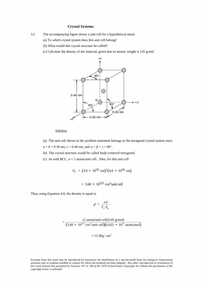
Crystal Systems 3.2 The accompanying figure shows a unit cell for a hypothetical metal.
(a) To which crystal system does this unit cell belong?
(b) What would this crystal structure be called?
(c) Calculate the density of the material, given that its atomic weight is 145 g/mol.
Solution
(a) The unit cell shown in the problem statement belongs to the tetragonal crystal system since
a = b = 0.30 nm, c = 0.40 nm, and = = = 90.
(b) The crystal structure would be called body-centered tetragonal.
(c) As with BCC, n = 2 atoms/unit cell. Also, for this unit cell
VC = (3.0 ´ 10-8 cm)2(4.0 ´ 10-8 cm)
= 3.60 ´ 10-23 cm3/unit cell
Thus, using Equation 4.8, the density is equal to
r = nA
VC
NA
= (2 atoms/unit cell)(145 g/mol)
(3.60 ´ 10-23 cm3 /unit cell)(6.022 ´ 1023 atoms/mol)
=13.38g / cm3
Excerpts from this work may be reproduced by instructors for distribution on a not-for-profit basis for testing or instructional purposes only to students enrolled in courses for which the textbook has been adopted. Any other reproduction or translation of this work beyond that permitted by Sections 107 or 108 of the 1976 United States Copyright Act without the permission o f the copyright owner is unlawful.
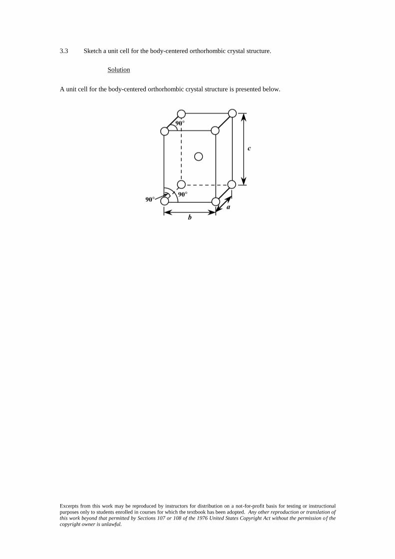
3.3 Sketch a unit cell for the body-centered orthorhombic crystal structure.
Solution
A unit cell for the body-centered orthorhombic crystal structure is presented below.

Excerpts from this work may be reproduced by instructors for distribution on a not-for-profit basis for testing or instructional purposes only to students enrolled in courses for which the textbook has been adopted. Any other reproduction or translation of this work beyond that permitted by Sections 107 or 108 of the 1976 United States Copyright Act without the permission o f the copyright owner is unlawful.
Point Coordinates
3.4 List the point coordinates for all atoms that are associated with the FCC unit cell (Figure 3.1).
Solution
From Figure 3.1b, the atom located of the origin of the unit cell has the coordinates 000.
Coordinates for other atoms in the bottom face are 100, 110, 010, and
1
2
1
20. (The z coordinate for all
these points is zero.)
For the top unit cell face, the coordinates are 001, 101, 111, 011, and
1
2
1
21.
Coordinates for those atoms that are positioned at the centers of both side faces, and centers of
both front and back faces need to be specified. For the front and back-center face atoms, the
coordinates are
11
2
1
2 and
01
2
1
2, respectively. While for the left and right side center-face atoms, the
respective coordinates are
1
20
1
2 and
1
21
1
2.

Excerpts from this work may be reproduced by instructors for distribution on a not-for-profit basis for testing or instructional purposes only to students enrolled in courses for which the textbook has been adopted. Any other reproduction or translation of this work beyond that permitted by Sections 107 or 108 of the 1976 United States Copyright Act without the permission o f the copyright owner is unlawful.
3.5 List the point coordinates of the titanium, barium, and oxygen ions for a unit cell of the
perovskite crystal structure (Figure 4.9).
Solution
In Figure 4.9, the barium ions are situated at all corner positions. The point coordinates for
these ions are as follows: 000, 100, 110, 010, 001, 101, 111, and 011.
The oxygen ions are located at all face-centered positions; therefore, their coordinates are
1
2
1
20,
1
2
1
21,
11
2
1
2,
01
2
1
2,
1
20
1
2, and
1
21
1
2.
And, finally, the titanium ion resides at the center of the cubic unit cell, with coordinates
1
2
1
2
1
2.

Excerpts from this work may be reproduced by instructors for distribution on a not-for-profit basis for testing or instructional purposes only to students enrolled in courses for which the textbook has been adopted. Any other reproduction or translation of this work beyond that permitted by Sections 107 or 108 of the 1976 United States Copyright Act without the permission o f the copyright owner is unlawful.
3.6 List the point coordinates of all atoms that are associated with the diamond cubic unit cell
(Figure 4.17).
Solution
First of all, one set of carbon atoms occupy all corner positions of the cubic unit cell; the
coordinates of these atoms are as follows: 000, 100, 110, 010, 001, 101, 111, and 011.
Another set of atoms reside on all of the face-centered positions, with the following
coordinates:
1
2
1
20,
1
2
1
21,
11
2
1
2,
01
2
1
2,
1
20
1
2, and
1
21
1
2.
The third set of carbon atoms are positioned within the interior of the unit cell. Using an x-y-z
coordinate system oriented as in Figure 3.2, the coordinates of the atom that lies toward the lower-left-
front of the unit cell has the coordinates
3
4
1
4
1
4, whereas the atom situated toward the lower-right-back
of the unit cell has coordinates of
1
4
3
4
1
4. Also, the carbon atom that resides toward the upper-left-back
of the unit cell has the
1
4
1
4
3
4 coordinates. And, the coordinates of the final atom, located toward the
upper-right-front of the unit cell, are
3
4
3
4
3
4.
Excerpts from this work may be reproduced by instructors for distribution on a not-for-profit basis for testing or instructional purposes only to students enrolled in courses for which the textbook has been adopted. Any other reproduction or translation of this work beyond that permitted by Sections 107 or 108 of the 1976 United States Copyright Act without the permission o f the copyright owner is unlawful.
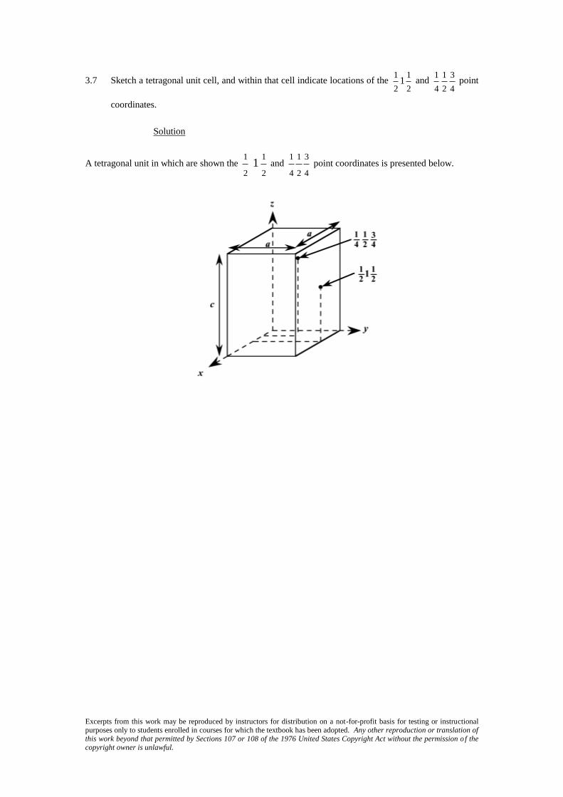
3.7 Sketch a tetragonal unit cell, and within that cell indicate locations of the 1
2 1
1
2 and
1
4 1
2 3
4 point
coordinates.
Solution
A tetragonal unit in which are shown the 1
2 1
1
2 and
1
4
1
2
3
4 point coordinates is presented below.

Excerpts from this work may be reproduced by instructors for distribution on a not-for-profit basis for testing or instructional purposes only to students enrolled in courses for which the textbook has been adopted. Any other reproduction or translation of this work beyond that permitted by Sections 107 or 108 of the 1976 United States Copyright Act without the permission o f the copyright owner is unlawful.
3.8 Using the Molecule Definition Utility found in both “Metallic Crystal Structures and
Crystallography” and “Ceramic Crystal Structures” modules of VMSE, available in WileyPlus,
generate a three-dimensional unit cell for the intermetallic compound AuCu3 given the following:
(1) the unit cell is cubic with an edge length of 0.374 nm, (2) gold atoms are situated at all cube
corners, and (3) copper atoms are positioned at the centers of all unit cell faces.
Solution
First of all, open the “Molecular Definition Utility”; it may be found in either of “Metallic
Crystal Structures and Crystallography” or “Ceramic Crystal Structures” modules.
In the “Step 1” window, it is necessary to define the atom types, colors for the spheres (atoms),
and specify atom sizes. Let us enter “Au” as the name for the gold atoms (since Au is the symbol for
gold), and “Cu” as the name for the copper atoms. Next it is necessary to choose a color for each atom
type from the selections that appear in the pull-down menu—for example, “Yellow” for Au and “Red”
for Cu. In the “Atom Size” window, it is necessary to enter an atom/ion size. In the instructions for this
step, it is suggested that the atom/ion diameter in nanometers be used. From the table found inside the
front cover of the textbook, the atomic radii for gold and copper are 0.144 nm and 0.128 nm,
respectively, and, therefore, their ionic diameters are twice these values (i.e., 0.288 nm and 0.256 nm);
therefore, we enter the values “0.288” and “0.256” for the two atom types. Now click on the “Register”
button, followed by clicking on the “Go to Step 2” button.
In the “Step 2” window we specify positions for all of the atoms within the unit cell; their point
coordinates are specified in the problem statement. Let’s begin with gold. Click on the yellow sphere
that is located to the right of the “Molecule Definition Utility” box. Again, Au atoms are situated at all
eight corners of the cubic unit cell. One Au will be positioned at the origin of the coordinate system—
i.e., its point coordinates are 000, and, therefore, we enter a “0” (zero) in each of the “x”, “y”, and “z”
atom position boxes. Next we click on the “Register Atom Position” button. Now we enter the
coordinates of another gold atom; let us arbitrarily select the one that resides at the corner of the unit
cell that is one unit-cell length along the x-axis (i.e., at the 100 point coordinate). Inasmuch as it is
located a distance of a units along the x-axis the value of “0.374” is entered in the “x” atom position
box (since this is the value of a given in the problem statement); zeros are entered in each of the “y”
and “z” position boxes. We repeat this procedure for the remaining six Au atoms.
After this step has been completed, it is necessary to specify positions for the copper atoms,
which are located at all six face-centered sites. To begin, we click on the red sphere that is located next
to the “Molecule Definition Utility” box. The point coordinates for some of the Cu atoms are fractional
ones; in these instances, the a unit cell length (i.e., 0.374) is multiplied by the fraction. For example,
one Cu atom is located
11
2
1
2 coordinate. Therefore, the x, y, and z atoms positions are (1)(0.374) =
0.374,
1
2(0.374) = 0.187, and
1
2(0.374) = 0.187, respectively.

Excerpts from this work may be reproduced by instructors for distribution on a not-for-profit basis for testing or instructional purposes only to students enrolled in courses for which the textbook has been adopted. Any other reproduction or translation of this work beyond that permitted by Sections 107 or 108 of the 1976 United States Copyright Act without the permission o f the copyright owner is unlawful.
For the gold atoms, the x, y, and z atom position entries for all 8 sets of point coordinates are
as follows:
0, 0, 0
0.374, 0, 0
0, 0.374, 0
0, 0, 0.374
0, 0.374, 0.374
0.374, 0, 0.374
0.374, 0.374, 0
0.374, 0.374, 0.374
Now, for the copper atoms, the x, y, and z atom position entries for all 6 sets of point
coordinates are as follows:
0.187, 0.187, 0
0.187, 0, 0.187
0, 0.187, 0.187
0.374, 0.187, 0.187
0.187, 0.374, 0.187
0.187, 0.187, 0.374
In Step 3, we may specify which atoms are to be represented as being bonded to one another,
and which type of bond(s) to use (single solid, single dashed, double, and triple are possibilities), or we
may elect to not represent any bonds at all (in which case we are finished). If it is decided to show
bonds, probably the best thing to do is to represent unit cell edges as bonds. This image may be rotated
by using mouse click-and-drag
Your image should appear as the following screen shot. Here the gold atoms appear lighter
than the copper atoms.
Excerpts from this work may be reproduced by instructors for distribution on a not-for-profit basis for testing or instructional purposes only to students enrolled in courses for which the textbook has been adopted. Any other reproduction or translation of this work beyond that permitted by Sections 107 or 108 of the 1976 United States Copyright Act without the permission o f the copyright owner is unlawful.
[Note: Unfortunately, with this version of the Molecular Definition Utility, it is not possible to save
either the data or the image that you have generated. You may use screen capture (or screen shot)
software to record and store your image.]
Excerpts from this work may be reproduced by instructors for distribution on a not-for-profit basis for testing or instructional purposes only to students enrolled in courses for which the textbook has been adopted. Any other reproduction or translation of this work beyond that permitted by Sections 107 or 108 of the 1976 United States Copyright Act without the permission o f the copyright owner is unlawful.
Crystallographic Directions
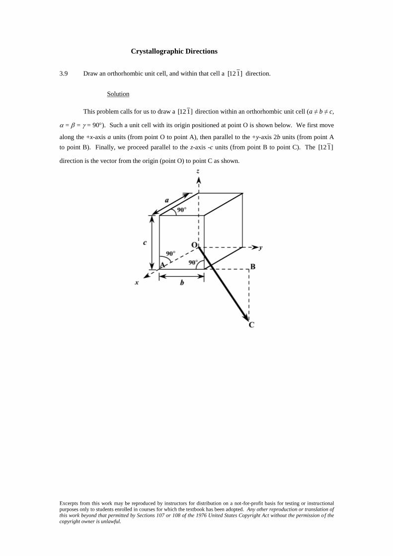
3.9 Draw an orthorhombic unit cell, and within that cell a [121] direction.
Solution
This problem calls for us to draw a [121] direction within an orthorhombic unit cell (a ≠ b ≠ c,
= = = 90). Such a unit cell with its origin positioned at point O is shown below. We first move
along the +x-axis a units (from point O to point A), then parallel to the +y-axis 2b units (from point A
to point B). Finally, we proceed parallel to the z-axis -c units (from point B to point C). The [121]
direction is the vector from the origin (point O) to point C as shown.

Excerpts from this work may be reproduced by instructors for distribution on a not-for-profit basis for testing or instructional purposes only to students enrolled in courses for which the textbook has been adopted. Any other reproduction or translation of this work beyond that permitted by Sections 107 or 108 of the 1976 United States Copyright Act without the permission o f the copyright owner is unlawful.
3.10 Sketch a monoclinic unit cell, and within that cell a [011] direction.
Solution
This problem asks that a [011] direction be drawn within a monoclinic unit cell (a ≠ b ≠ c, and
= = 90 ≠ ). One such unit cell with its origin at point O is sketched below. For this direction,
there is no projection along the x-axis since the first index is zero; thus, the direction lies in the y-z
plane. We next move from the origin along the minus y-axis b units (from point O to point R). Since
the final index is a one, move from point R parallel to the z-axis, c units (to point P). Thus, the [011]
direction corresponds to the vector passing from the origin (point O) to point P, as indicated in the
figure.

Excerpts from this work may be reproduced by instructors for distribution on a not-for-profit basis for testing or instructional purposes only to students enrolled in courses for which the textbook has been adopted. Any other reproduction or translation of this work beyond that permitted by Sections 107 or 108 of the 1976 United States Copyright Act without the permission o f the copyright owner is unlawful.
3.11 What are the indices for the directions indicated by the two vectors in the following sketch?
Solution
This is a
[012 ] direction as indicated in the summary below.
x y z
Head coordinates (x2, y2, z2) 0a b/2 c
Tail coordinates (x1, y1, z1) 0a 0b 0c
Coordinate differences 0a b/2 c
Calculated values of u, v, and w u = 0 v = 1 w = 2
Enclosure
[012 ]
Direction 2 is
[112 ] as summarized below.
x y z
Head coordinates (x2, y2, z2) a/2 b/2 -c
Tail coordinates (x1, y1, z1) 0a 0b 0c
Coordinate differences a/2 b/2 -c
Calculated values of u, v, and w u = 1 v = 1 w = -2
Enclosure
[112 ]

Excerpts from this work may be reproduced by instructors for distribution on a not-for-profit basis for testing or instructional purposes only to students enrolled in courses for which the textbook has been adopted. Any other reproduction or translation of this work beyond that permitted by Sections 107 or 108 of the 1976 United States Copyright Act without the permission o f the copyright owner is unlawful.
3.12 Within a cubic unit cell, sketch the following directions:
(a) [110] , (e) [111] ,
(b) [121] , (f) [122] ,
(c) [012] , (g) [123] ,
(d) [133] , (h)
[1 03].
Solution
The directions asked for are indicated in the cubic unit cells shown below.

Excerpts from this work may be reproduced by instructors for distribution on a not-for-profit basis for testing or instructional purposes only to students enrolled in courses for which the textbook has been adopted. Any other reproduction or translation of this work beyond that permitted by Sections 107 or 108 of the 1976 United States Copyright Act without the permission o f the copyright owner is unlawful.
3.13 Determine the indices for the directions shown in the following cubic unit cell:
Solution
Direction A is a
[01 1 ] direction. To solve this problem, we first take note of the vector tail
and head coordinates, then take the point coordinate differences. We then use Equation 3.2 selecting a
value of n that will produce integer values of u, v, and w. In this case select n = 1 as there are no
fractions in the differences. Finally, the values of u, v, and w are enclosed in brackets to give the
direction designation. This is summarized as follows:
x y z
Head coordinates (x2, y2, z2) 0a 0b 0c
Tail coordinates (x1, y1, z1) 0a b c
Coordinate differences 0a -b -c
Calculated values of u, v, and w u = 0 v = -1 w = -1
Enclosure
[01 1 ]
Direction B is a
[2 10] direction as indicated in the summary below.
x y z
Head coordinates (x2, y2, z2) 0a b c
Tail coordinates (x1, y1, z1) a b/2 c
Coordinate differences -a b/2 0
Calculated values of u, v, and w u = -2 v = 1 w = 0
Enclosure
[2 10]

Excerpts from this work may be reproduced by instructors for distribution on a not-for-profit basis for testing or instructional purposes only to students enrolled in courses for which the textbook has been adopted. Any other reproduction or translation of this work beyond that permitted by Sections 107 or 108 of the 1976 United States Copyright Act without the permission o f the copyright owner is unlawful.
Direction C is a [112] direction as indicated in the summary below. x y z
Head coordinates (x2, y2, z2) a b c
Tail coordinates (x1, y1, z1) a/2 b/2 0c
Coordinate differences a/2 b/2 c
Calculated values of u, v, and w u = 1 v = 1 w = 2
Enclosure [112]
Direction D is a
[112 ] direction as indicated in the summary below.
x y z
Head coordinates (x2, y2, z2) a b/2 0c
Tail coordinates (x1, y1, z1) a/2 0b c
Coordinate differences a/2 b/2 -c
Calculated values of u, v, and w u = 1 v = 1 w = -2
Enclosure
[112 ]

Excerpts from this work may be reproduced by instructors for distribution on a not-for-profit basis for testing or instructional purposes only to students enrolled in courses for which the textbook has been adopted. Any other reproduction or translation of this work beyond that permitted by Sections 107 or 108 of the 1976 United States Copyright Act without the permission o f the copyright owner is unlawful.
3.14 Determine the indices for the directions shown in the following cubic unit cell:
Solution
Direction A is a
[4 30] direction. To solve this problem, we first take note of the vector tail
and head coordinates, then take the point coordinate differences. We then use Equation 3.2 selecting a
value of n that will produce integer values of u, v, and w. In this case select n = 1 as there are no
fractions in the differences. Finally, the values of u, v, and w are enclosed in brackets to give the
direction designation. This is summarized as follows:
x y z
Head coordinates (x2, y2, z2) 0a b/2 c
Tail coordinates (x1, y1, z1) 2a/3 0b c
Coordinate differences -2a/3 b/2 0c
Calculated values of u, v, and w u = -4 v = 3 w = 0
Enclosure
[4 30]
Direction B is a
[23 2] direction as indicated in the summary below.
x y z
Head coordinates (x2, y2, z2) a 0b 2c/3
Tail coordinates (x1, y1, z1) a/3 b 0c
Coordinate differences 2a/3 -b 2c/3
Calculated values of u, v, and w u = 2 v = -3 w = 2
Enclosure
[23 2]
Excerpts from this work may be reproduced by instructors for distribution on a not-for-profit basis for testing or instructional purposes only to students enrolled in courses for which the textbook has been adopted. Any other reproduction or translation of this work beyond that permitted by Sections 107 or 108 of the 1976 United States Copyright Act without the permission o f the copyright owner is unlawful.
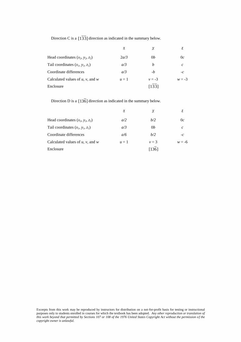
Direction C is a
[13 3 ] direction as indicated in the summary below.
x y z
Head coordinates (x2, y2, z2) 2a/3 0b 0c
Tail coordinates (x1, y1, z1) a/3 b c
Coordinate differences a/3 -b -c
Calculated values of u, v, and w u = 1 v = -3 w = -3
Enclosure
[13 3 ]
Direction D is a
[136 ] direction as indicated in the summary below.
x y z
Head coordinates (x2, y2, z2) a/2 b/2 0c
Tail coordinates (x1, y1, z1) a/3 0b c
Coordinate differences a/6 b/2 -c
Calculated values of u, v, and w u = 1 v = 3 w = -6
Enclosure
[136 ]

Excerpts from this work may be reproduced by instructors for distribution on a not-for-profit basis for testing or instructional purposes only to students enrolled in courses for which the textbook has been adopted. Any other reproduction or translation of this work beyond that permitted by Sections 107 or 108 of the 1976 United States Copyright Act without the permission o f the copyright owner is unlawful.
3.15 For tetragonal crystals, cite the indices of directions that are equivalent to each of the following
directions:
(a) [001]
(b) [110]
(c) [010]
Solution
For tetragonal crystals a = b ≠ c and = = = 90; therefore, projections along the x and y axes are
equivalent, which are not equivalent to projections along the z axis.
(a) Therefore, for the [001] direction, there is only one equivalent direction:
[001 ].
(b) For the [110] direction, equivalent directions are as follows:
[1 1 0],
[1 10], and
[11 0]
(b) Also, for the [010] direction, equivalent directions are the following:
[01 0],
[100], and
[1 00].
Excerpts from this work may be reproduced by instructors for distribution on a not-for-profit basis for testing or instructional purposes only to students enrolled in courses for which the textbook has been adopted. Any other reproduction or translation of this work beyond that permitted by Sections 107 or 108 of the 1976 United States Copyright Act without the permission o f the copyright owner is unlawful.
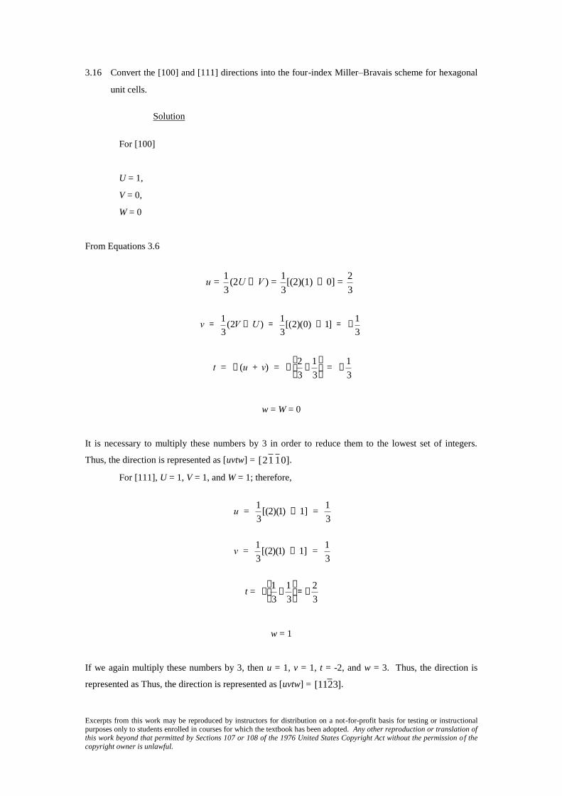
3.16 Convert the [100] and [111] directions into the four-index Miller–Bravais scheme for hexagonal
unit cells.
Solution
For [100]
U = 1,
V = 0,
W = 0
From Equations 3.6
u = 1
3(2U - V ) =
1
3[(2)(1) - 0] =
2
3
v = 1
3(2V - U ) =
1
3[(2)(0) - 1] = -
1
3
t = - (u + v) = -2
3-
1
3
æ
è ç
ö
ø ÷ = -
1
3
w = W = 0
It is necessary to multiply these numbers by 3 in order to reduce them to the lowest set of integers.
Thus, the direction is represented as [uvtw] =
[21 1 0].
For [111], U = 1, V = 1, and W = 1; therefore,
u = 1
3[(2)(1) - 1] =
1
3
v = 1
3[(2)(1) - 1] =
1
3
t =
-1
3+
1
3
æ
è ç
ö
ø ÷ = -
2
3
w = 1
If we again multiply these numbers by 3, then u = 1, v = 1, t = -2, and w = 3. Thus, the direction is
represented as Thus, the direction is represented as [uvtw] =
[112 3].

Excerpts from this work may be reproduced by instructors for distribution on a not-for-profit basis for testing or instructional purposes only to students enrolled in courses for which the textbook has been adopted. Any other reproduction or translation of this work beyond that permitted by Sections 107 or 108 of the 1976 United States Copyright Act without the permission o f the copyright owner is unlawful.
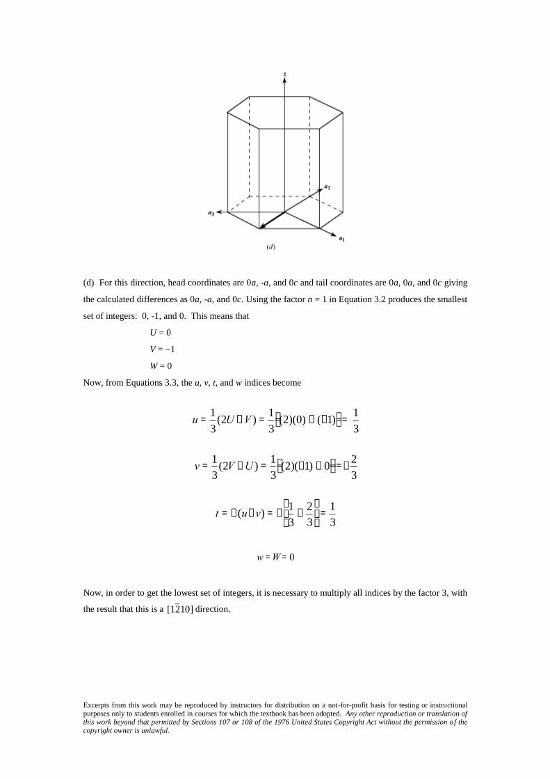
3.17 Determine indices for the directions shown in the following hexagonal unit cells:
Solution
(a) For this direction, head coordinates are a, a/2, and c/2 and tail coordinates are 0a, 0a, and 0c giving
the calculated differences as a, a/2, and c/2. Using the factor n = 2 in Equation 3.2 produces the
smallest set of integers: 2, 1, and 1. This means that
U = 2
V = 1
W = 1
Now, from Equations 3.3, the u, v, t, and w indices become
u =1
3(2U - V ) =
1
3(2)(2) - (1)é
ëùû =
3
3 = 1
v =1
3(2V - U ) =
1
3(2)(1) - (2)é
ëùû = 0
t = - (u + v) = - 1 + 0( ) = -1
w = W = 1
No reduction is necessary inasmuch as all of these indices are integers; therefore, this direction in the
four-index scheme is
[101 1]

Excerpts from this work may be reproduced by instructors for distribution on a not-for-profit basis for testing or instructional purposes only to students enrolled in courses for which the textbook has been adopted. Any other reproduction or translation of this work beyond that permitted by Sections 107 or 108 of the 1976 United States Copyright Act without the permission o f the copyright owner is unlawful.
(b) For this direction, head coordinates are a/2, a, and 0c and tail coordinates are 0a, 0a, and 0c giving
the calculated differences as a/2, a, and 0c. Using the factor n = 2 in Equation 3.2 produces the smallest
set of integers: 1, 2, and 0. This means that
U = 1
V = 2
W = 0
Now, from Equations 3.3, the u, v, t, and w indices become
u =1
3(2U - V ) =
1
3(2)(1) - 2é
ëùû = 0
v =1
3(2V - U ) =
1
3(2)(2) - 1é
ëùû = 1
t = - (u+v) = - 0 + 1( ) = -1
w = W = 0
No reduction is necessary inasmuch as all of these indices are integers; therefore, this direction in the
four-index scheme is
[011 0].

Excerpts from this work may be reproduced by instructors for distribution on a not-for-profit basis for testing or instructional purposes only to students enrolled in courses for which the textbook has been adopted. Any other reproduction or translation of this work beyond that permitted by Sections 107 or 108 of the 1976 United States Copyright Act without the permission o f the copyright owner is unlawful.
(c) For this direction, head coordinates are -a, -a, and c/2 and tail coordinates are 0a, 0a, and 0c giving
the calculated differences as -a, a, and c/2. Using the factor n = 2 in Equation 3.2 produces the smallest
set of integers: -2, -2, and 1. This means that
U = 2
V = 2
W = 1
Now, from Equations 3.3, the u, v, t, and w indices become
u =1
3(2U - V ) =
1
3(2)(-2) -(-2)é
ëùû =-
2
3
v =1
3(2V - U ) =
1
3(2)(-2) - (-2)é
ëùû = -
2
3
t = -(u+v) = - -2
3-
2
3
æ
èç
ö
ø÷ =
4
3
w = W = 1
Now, in order to get the lowest set of integers, it is necessary to multiply all indices by the factor 3, with
the result that this direction is a
[2 2 43] direction.
Excerpts from this work may be reproduced by instructors for distribution on a not-for-profit basis for testing or instructional purposes only to students enrolled in courses for which the textbook has been adopted. Any other reproduction or translation of this work beyond that permitted by Sections 107 or 108 of the 1976 United States Copyright Act without the permission o f the copyright owner is unlawful.
(d) For this direction, head coordinates are 0a, -a, and 0c and tail coordinates are 0a, 0a, and 0c giving
the calculated differences as 0a, -a, and 0c. Using the factor n = 1 in Equation 3.2 produces the smallest
set of integers: 0, -1, and 0. This means that
U = 0
V = 1
W = 0
Now, from Equations 3.3, the u, v, t, and w indices become
u =1
3(2U - V ) =
1
3(2)(0) - (-1)é
ëùû =
1
3
v =1
3(2V - U ) =
1
3(2)(-1) - 0é
ëùû =-
2
3
t = -(u+v) = -1
3-
2
3
æ
èç
ö
ø÷ =
1
3
w = W = 0
Now, in order to get the lowest set of integers, it is necessary to multiply all indices by the factor 3, with
the result that this is a
[12 10] direction.
Excerpts from this work may be reproduced by instructors for distribution on a not-for-profit basis for testing or instructional purposes only to students enrolled in courses for which the textbook has been adopted. Any other reproduction or translation of this work beyond that permitted by Sections 107 or 108 of the 1976 United States Copyright Act without the permission o f the copyright owner is unlawful.
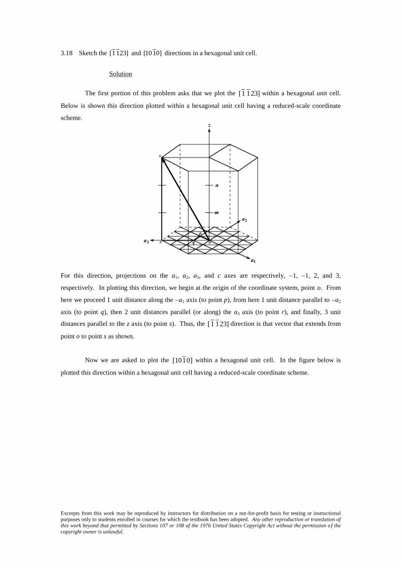
3.18 Sketch the [1123] and [1010] directions in a hexagonal unit cell.
Solution
The first portion of this problem asks that we plot the
[1 1 23] within a hexagonal unit cell.
Below is shown this direction plotted within a hexagonal unit cell having a reduced-scale coordinate
scheme.
For this direction, projections on the a1, a2, a3, and c axes are respectively, 1, 1, 2, and 3,
respectively. In plotting this direction, we begin at the origin of the coordinate system, point o. From
here we proceed 1 unit distance along the a1 axis (to point p), from here 1 unit distance parallel to a2
axis (to point q), then 2 unit distances parallel (or along) the a3 axis (to point r), and finally, 3 unit
distances parallel to the z axis (to point s). Thus, the
[1 1 23] direction is that vector that extends from
point o to point s as shown.
Now we are asked to plot the
[101 0] within a hexagonal unit cell. In the figure below is
plotted this direction within a hexagonal unit cell having a reduced-scale coordinate scheme.

Excerpts from this work may be reproduced by instructors for distribution on a not-for-profit basis for testing or instructional purposes only to students enrolled in courses for which the textbook has been adopted. Any other reproduction or translation of this work beyond that permitted by Sections 107 or 108 of the 1976 United States Copyright Act without the permission o f the copyright owner is unlawful.
For this direction, projections on the a1, a2, a3, and c axes are respectively, 1, 0, 1, and 0, respectively.
In plotting this direction, we begin at the origin of the coordinate system, point o. From here we
proceed 1 unit distance along the a1 axis (to point p). Since there is no projection on the a2 axis it is not
necessary to move parallel to this axis. Therefore, from point p we proceed 1 unit distance parallel to
a3 axis (to point q). And, finally, inasmuch as there is no projection along the z axis, it is not
necessary to move parallel to this axis. Thus, the
[101 0] direction is that vector that extends from
point o to point q as shown.

Excerpts from this work may be reproduced by instructors for distribution on a not-for-profit basis for testing or instructional purposes only to students enrolled in courses for which the textbook has been adopted. Any other reproduction or translation of this work beyond that permitted by Sections 107 or 108 of the 1976 United States Copyright Act without the permission o f the copyright owner is unlawful.
3.19 Using Equations 3.3a, 3.3b, 3.3c, and 3.3d, derive expressions for each of the three primed
indices set (U′, V, and W) in terms of the four unprimed indices (u, v, t, and w).
Solution
It is first necessary to do an expansion of Equation 3.3a as
u =1
3(2U - V ) =
2U
3-
V
3
And solving this expression for V yields
V = 2U - 3u
Now, substitution of this expression into Equation 3.3b gives
v =1
3(2V - U ) =
1
3(2)(2U - 3u) - Ué
ëùû = U - 2u
or
U = v + 2u
And, solving for v from Equation 3.3c leads to
v = - (u + t)
which, when substituted into the above expression for U yields
U = v + 2u = -u -t + 2u = u - t
In solving for an expression for V, we begin with the one of the above expressions for this
parameter—i.e.,
V = 2U - 3u
Now, substitution of the above expression for U into this equation leads to
V = 2U - 3u = (2)(u - t) - 3u = -u -2t
Excerpts from this work may be reproduced by instructors for distribution on a not-for-profit basis for testing or instructional purposes only to students enrolled in courses for which the textbook has been adopted. Any other reproduction or translation of this work beyond that permitted by Sections 107 or 108 of the 1976 United States Copyright Act without the permission o f the copyright owner is unlawful.
And solving for u from Equation 3.3c gives
u = -v - t
which, when substituted in the previous equation results in the following expression for V
V = -u -2t = -(-v -t) - 2t = v - t
And, of course from Equation 3.3d
W = w

Excerpts from this work may be reproduced by instructors for distribution on a not-for-profit basis for testing or instructional purposes only to students enrolled in courses for which the textbook has been adopted. Any other reproduction or translation of this work beyond that permitted by Sections 107 or 108 of the 1976 United States Copyright Act without the permission o f the copyright owner is unlawful.
Crystallographic Planes
3.20 (a) Draw an orthorhombic unit cell, and within that cell a (210) plane.
(b) Draw a monoclinic unit cell, and within that cell a (002) plane.
Solution
(a) We are asked to draw a (210) plane within an orthorhombic unit cell. First remove the three indices
from the parentheses, and take their reciprocals–i.e., 1/2, 1, and ∞. This means that the plane intercepts
the x-axis at a/2, the y-axis at b, and parallels the z-axis. The plane that satisfies these requirements has
been drawn within the orthorhombic unit cell below. (For orthorhombic, a ≠ b ≠ c, and = = =
90.)
(b) A (002) plane is drawn within the monoclinic cell shown below. We first remove the parentheses
and take the reciprocals of the indices; this gives , , and 1/2. Thus, the (002) plane parallels both x-
and y-axes, and intercepts the z-axis at a/2, as indicated in the drawing. (For monoclinic, a ≠ b ≠ c, and
= = 90 ≠ .)
Excerpts from this work may be reproduced by instructors for distribution on a not-for-profit basis for testing or instructional purposes only to students enrolled in courses for which the textbook has been adopted. Any other reproduction or translation of this work beyond that permitted by Sections 107 or 108 of the 1976 United States Copyright Act without the permission o f the copyright owner is unlawful.
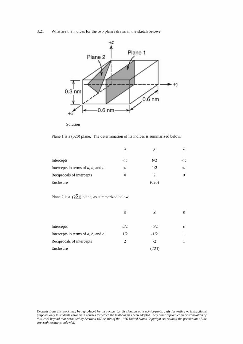
3.21 What are the indices for the two planes drawn in the sketch below?
Solution
Plane 1 is a (020) plane. The determination of its indices is summarized below.
x y z
Intercepts a b/2 c
Intercepts in terms of a, b, and c 1/2
Reciprocals of intercepts 0 2 0
Enclosure (020)
Plane 2 is a
(22 1) plane, as summarized below.
x y z
Intercepts a/2 -b/2 c
Intercepts in terms of a, b, and c 1/2 -1/2 1
Reciprocals of intercepts 2 -2 1
Enclosure
(22 1)

Excerpts from this work may be reproduced by instructors for distribution on a not-for-profit basis for testing or instructional purposes only to students enrolled in courses for which the textbook has been adopted. Any other reproduction or translation of this work beyond that permitted by Sections 107 or 108 of the 1976 United States Copyright Act without the permission o f the copyright owner is unlawful.
3.22 Sketch within a cubic unit cell the following planes:
(a) (011) , (e) (111) ,
(b) (112) , (f) (122) ,
(c) (102) , (g) (123) ,
(d) (131) , (h) (013)
Solution
The planes called for are plotted in the cubic unit cells shown below.

Excerpts from this work may be reproduced by instructors for distribution on a not-for-profit basis for testing or instructional purposes only to students enrolled in courses for which the textbook has been adopted. Any other reproduction or translation of this work beyond that permitted by Sections 107 or 108 of the 1976 United States Copyright Act without the permission o f the copyright owner is unlawful.
3.23 Determine the Miller indices for the planes shown in the following unit cell:
Solution
For plane A we will leave the origin at the unit cell as shown; this is a (403) plane, as
summarized below.
x y z
Intercepts
a
2 b
2c
3
Intercepts in terms of a, b, and c
1
2
2
3
Reciprocals of intercepts 2 0
3
2
Reduction 4 0 3
Enclosure (403)
For plane B we will move the origin of the unit cell one unit cell distance to the right along the
y axis, and one unit cell distance parallel to the x axis; thus, this is a
(1 1 2) plane, as summarized
below.
x y z
Intercepts – a – b
c
2
Intercepts in terms of a, b, and c – 1 – 1
1
2
Reciprocals of intercepts – 1 – 1 2
Reduction (not necessary)
Enclosure
(1 1 2)

Excerpts from this work may be reproduced by instructors for distribution on a not-for-profit basis for testing or instructional purposes only to students enrolled in courses for which the textbook has been adopted. Any other reproduction or translation of this work beyond that permitted by Sections 107 or 108 of the 1976 United States Copyright Act without the permission o f the copyright owner is unlawful.
3.24 Determine the Miller indices for the planes shown in the following unit cell:
Solution
For plane A we will move the origin of the coordinate system one unit cell distance to the
upward along the z axis; thus, this is a
(322 ) plane, as summarized below.
x y z
Intercepts
a
3
b
2 –
c
2
Intercepts in terms of a, b, and c
1
3
1
2 –
1
2
Reciprocals of intercepts 3 2 – 2
Reduction (not necessary)
Enclosure
(322 )
For plane B we will move the original of the coordinate system on unit cell distance along the
x axis; thus, this is a
(1 01) plane, as summarized below.
x y z
Intercepts –
a
2 b
c
2
Intercepts in terms of a, b, and c –
1
2
1
2
Reciprocals of intercepts – 2 0 2
Reduction – 1 0 1
Enclosure
(1 01)

Excerpts from this work may be reproduced by instructors for distribution on a not-for-profit basis for testing or instructional purposes only to students enrolled in courses for which the textbook has been adopted. Any other reproduction or translation of this work beyond that permitted by Sections 107 or 108 of the 1976 United States Copyright Act without the permission o f the copyright owner is unlawful.
3.25 Determine the Miller indices for the planes shown in the following unit cell:
Solution
For plane A since the plane passes through the origin of the coordinate system as shown, we
will move the origin of the coordinate system one unit cell distance to the right along the y axis; thus,
this is a
(32 4) plane, as summarized below.
x y z
Intercepts
2a
3 – b
c
2
Intercepts in terms of a, b, and c
2
3 – 1
1
2
Reciprocals of intercepts
3
2 – 1 2
Reduction 3 – 2 4
Enclosure
(32 4)
For plane B we will leave the origin at the unit cell as shown; this is a (221) plane, as
summarized below.
x y z
Intercepts
a
2
b
2 c
Intercepts in terms of a, b, and c
1
2
1
2 1
Reciprocals of intercepts 2 2 1
Reduction not necessary
Enclosure (221)

Excerpts from this work may be reproduced by instructors for distribution on a not-for-profit basis for testing or instructional purposes only to students enrolled in courses for which the textbook has been adopted. Any other reproduction or translation of this work beyond that permitted by Sections 107 or 108 of the 1976 United States Copyright Act without the permission o f the copyright owner is unlawful.
3.26 Cite the indices of the direction that results from the intersection of each of the following pair of
planes within a cubic crystal: (a) (100) and (010) planes, (b) (111) and (111) planes, and (c)
(101) and (001) planes.
Solution
(a) In the figure below is shown (100) and (010) planes, and, as indicated, their intersection
results in a [001], or equivalently, a
[001 ] direction.
(b) In the figure below is shown (111) and
(111 ) planes, and, as indicated, their intersection results in
a
[1 10], or equivalently, a
[11 0] direction.

Excerpts from this work may be reproduced by instructors for distribution on a not-for-profit basis for testing or instructional purposes only to students enrolled in courses for which the textbook has been adopted. Any other reproduction or translation of this work beyond that permitted by Sections 107 or 108 of the 1976 United States Copyright Act without the permission o f the copyright owner is unlawful.
(c) In the figure below is shown
(101 ) and (001) planes, and, as indicated, their intersection results in a
[010], or equivalently, a
[01 0] direction.

Excerpts from this work may be reproduced by instructors for distribution on a not-for-profit basis for testing or instructional purposes only to students enrolled in courses for which the textbook has been adopted. Any other reproduction or translation of this work beyond that permitted by Sections 107 or 108 of the 1976 United States Copyright Act without the permission o f the copyright owner is unlawful.
3.27 Convert the (010) and (101) planes into the four-index Miller–Bravais scheme for hexagonal unit
cells.
Solution
For (010), h = 0, k = 1, and l = 0, and, from Equation 3.6, the value of i is equal to
i = - (h + k) = - (0 + 1) = -1
Therefore, the (010) plane becomes
(011 0).
Now for the (101) plane, h = 1, k = 0, and l = 1, and computation of i using Equation 3.6 leads
to
i = - (h + k) = -[1 + 0] = -1
such that (101) becomes
(101 1).
Excerpts from this work may be reproduced by instructors for distribution on a not-for-profit basis for testing or instructional purposes only to students enrolled in courses for which the textbook has been adopted. Any other reproduction or translation of this work beyond that permitted by Sections 107 or 108 of the 1976 United States Copyright Act without the permission o f the copyright owner is unlawful.
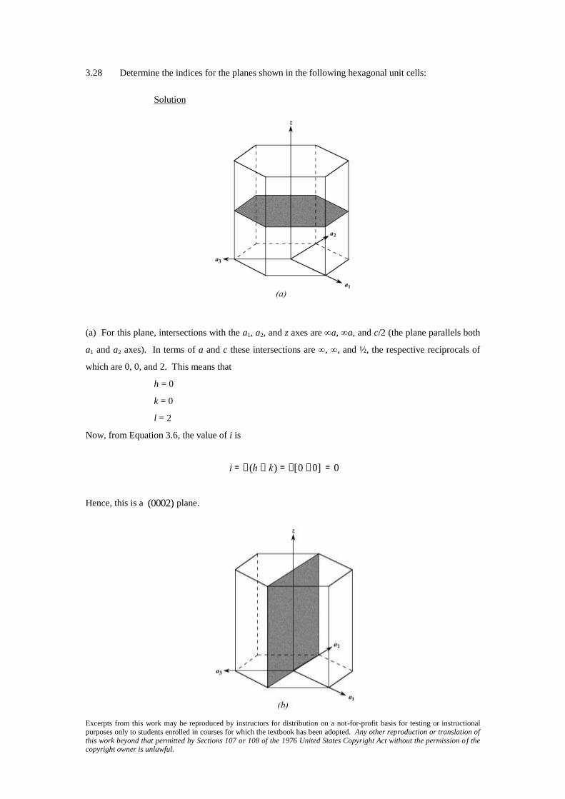
3.28 Determine the indices for the planes shown in the following hexagonal unit cells:
Solution
(a) For this plane, intersections with the a1, a2, and z axes are a, a, and c/2 (the plane parallels both
a1 and a2 axes). In terms of a and c these intersections are , , and ½, the respective reciprocals of
which are 0, 0, and 2. This means that
h = 0
k = 0
l = 2
Now, from Equation 3.6, the value of i is
i = - (h + k) = -[0 +0] = 0
Hence, this is a
(0002) plane.

Excerpts from this work may be reproduced by instructors for distribution on a not-for-profit basis for testing or instructional purposes only to students enrolled in courses for which the textbook has been adopted. Any other reproduction or translation of this work beyond that permitted by Sections 107 or 108 of the 1976 United States Copyright Act without the permission o f the copyright owner is unlawful.
(b) This plane passes through the origin of the coordinate axis system; therefore, we translate this plane
one unit distance along the x axis, per the sketch shown below:
At this point the plane intersects the a1, a2, and z axes at a, a, and c, respectively (the plane parallels
both a2 and z axes). In terms of a and c these intersections are 1, , and , the respective reciprocals of
which are 1, 0, and 0. This means that
h = 1
k = 0
l = 0
Now, from Equation 3.6, the value of i is
i = - (h + k) = - (1 + 0) = -1
Hence, this is a
(101 0) plane.

Excerpts from this work may be reproduced by instructors for distribution on a not-for-profit basis for testing or instructional purposes only to students enrolled in courses for which the textbook has been adopted. Any other reproduction or translation of this work beyond that permitted by Sections 107 or 108 of the 1976 United States Copyright Act without the permission o f the copyright owner is unlawful.
(c) For this plane, intersections with the a1, a2, and z axes are –a, a, and c. In terms of a and c these
intersections are –1, 1, and 1, the respective reciprocals of which are 0, 1, and 1. This means that
h = –1
k = 1
l = 1
Now, from Equation 3.6, the value of i is
i = - (h + k) = - (-1 + 1) = 0
Hence, this is a
(1 101) plane.
(d) For this plane, intersections with the a1, a2, and z axes are –a/2, a, and c/2, respectively. In terms of
a and c these intersections are –1/2, 1, and 1/2, the respective reciprocals of which are –2, 1, and 2.
This means that
h = –2
k = 1
l = 2
Now, from Equation 3.6, the value of i is
i = - (h + k) = - (-2 + 1) = 1
Therefore, this is a
(2 112) plane.
Excerpts from this work may be reproduced by instructors for distribution on a not-for-profit basis for testing or instructional purposes only to students enrolled in courses for which the textbook has been adopted. Any other reproduction or translation of this work beyond that permitted by Sections 107 or 108 of the 1976 United States Copyright Act without the permission o f the copyright owner is unlawful.
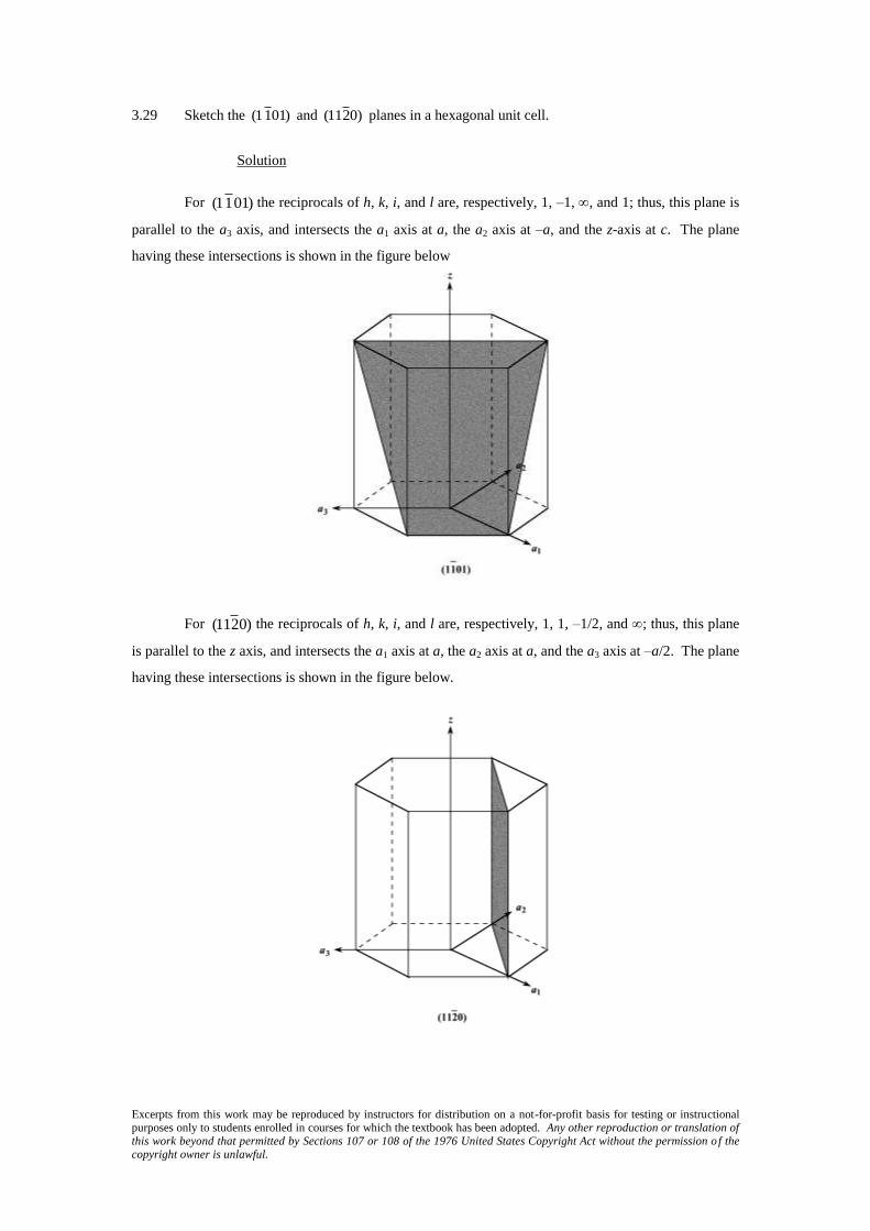
3.29 Sketch the (1101) and (1120) planes in a hexagonal unit cell.
Solution
For
(11 01) the reciprocals of h, k, i, and l are, respectively, 1, –1, , and 1; thus, this plane is
parallel to the a3 axis, and intersects the a1 axis at a, the a2 axis at –a, and the z-axis at c. The plane
having these intersections is shown in the figure below
For
(112 0) the reciprocals of h, k, i, and l are, respectively, 1, 1, –1/2, and ; thus, this plane
is parallel to the z axis, and intersects the a1 axis at a, the a2 axis at a, and the a3 axis at –a/2. The plane
having these intersections is shown in the figure below.

Excerpts from this work may be reproduced by instructors for distribution on a not-for-profit basis for testing or instructional purposes only to students enrolled in courses for which the textbook has been adopted. Any other reproduction or translation of this work beyond that permitted by Sections 107 or 108 of the 1976 United States Copyright Act without the permission o f the copyright owner is unlawful.
Polycrystalline Materials
3.30 Explain why the properties of polycrystalline materials are most often isotropic.
Solution
Although each individual grain in a polycrystalline material may be anisotropic, if the grains
have random orientations, then the solid aggregate of the many anisotropic grains will behave
isotropically.

Excerpts from this work may be reproduced by instructors for distribution on a not-for-profit basis for testing or instructional purposes only to students enrolled in courses for which the textbook has been adopted. Any other reproduction or translation of this work beyond that permitted by Sections 107 or 108 of the 1976 United States Copyright Act without the permission o f the copyright owner is unlawful.
Noncrystalline Solids
3.31 Would you expect a material in which the atomic bonding is predominantly ionic in nature to be
more or less likely to form a noncrystalline solid upon solidification than a covalent material?
Why? (See Section 2.6.)
Solution
A material in which atomic bonding is predominantly ionic in nature is less likely to form a
noncrystalline solid upon solidification than a covalent material because covalent bonds are directional
whereas ionic bonds are nondirectional; it is more difficult for the atoms in a covalent material to
assume positions giving rise to an ordered structure.