chapter 27 – magnetic induction · back emf in motor circuit notice that an electric motor can...
TRANSCRIPT

Chapter 27 – Magnetic Induction
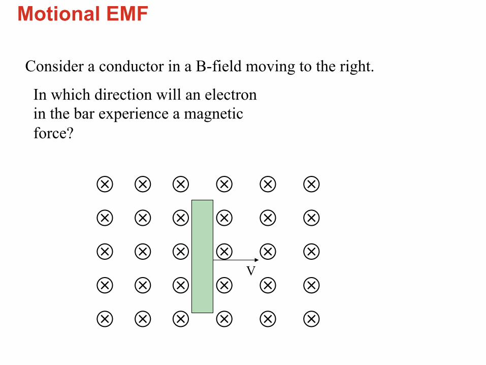
Motional EMF
Consider a conductor in a B-field moving to the right.
⊗⊗⊗⊗⊗⊗
⊗⊗⊗⊗⊗⊗
⊗⊗⊗⊗⊗⊗
⊗⊗⊗⊗⊗⊗
⊗⊗⊗⊗⊗⊗
V
In which direction will an electron in the bar experience a magnetic force?
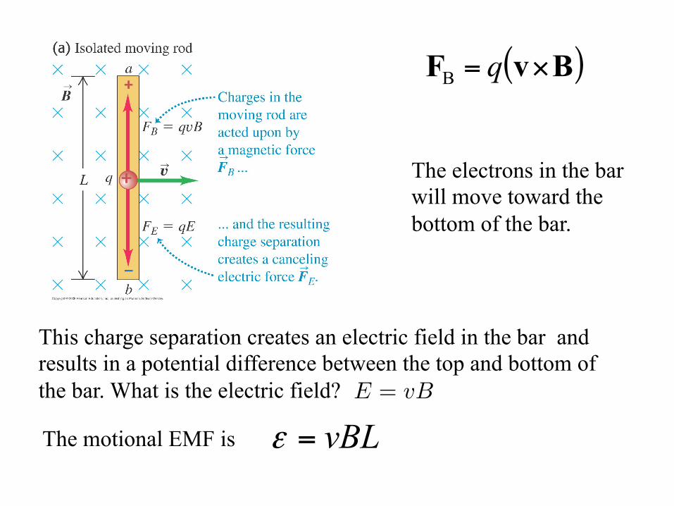
The electrons in the bar will move toward the bottom of the bar.
This charge separation creates an electric field in the bar and results in a potential difference between the top and bottom of the bar. What is the electric field?
( )BvF ×= qB
The motional EMF is vBL=εE = vB

What if the bar were placed across conducting rails (in red) so that there is a closed loop for the electrons to follow?
In this circuit, what direction is the current?
a) clockwise b) counterclockwise
⊗⊗⊗⊗⊗⊗
⊗⊗⊗⊗⊗⊗
⊗⊗⊗⊗⊗⊗
⊗⊗⊗⊗⊗⊗
⊗⊗⊗⊗⊗⊗
V L

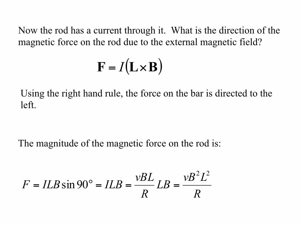
The magnitude of the magnetic force on the rod is:
RLvBLB
RvBLILBILBF
22
90sin ===°=
Now the rod has a current through it. What is the direction of the magnetic force on the rod due to the external magnetic field?
( )BLF ×= I
Using the right hand rule, the force on the bar is directed to the left.
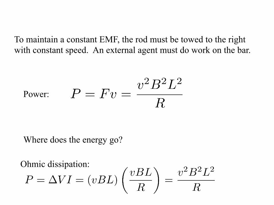
To maintain a constant EMF, the rod must be towed to the right with constant speed. An external agent must do work on the bar.
Power:
Ohmic dissipation:
Where does the energy go?

Induction • Motion of wire in B field induces an
emf (thus a current if circuit is closed). This is motional emf, and the emf is due to the magnetic field.
• Are there other ways? Can an emf be produced (induced) if the circuit is stationary?

Magnetic flux
ΦB =�
�B · d �A
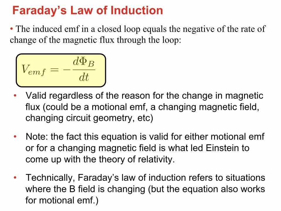
Faraday’s Law of Induction • The induced emf in a closed loop equals the negative of the rate of change of the magnetic flux through the loop:
• Valid regardless of the reason for the change in magnetic flux (could be a motional emf, a changing magnetic field, changing circuit geometry, etc)
• Note: the fact this equation is valid for either motional emf or for a changing magnetic field is what led Einstein to come up with the theory of relativity.
• Technically, Faraday’s law of induction refers to situations where the B field is changing (but the equation also works for motional emf.)
Vemf = −dΦB
dt
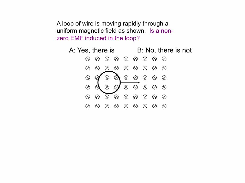
CT 33.3
A loop of wire is moving rapidly through a uniform magnetic field as shown. Is a non-zero EMF induced in the loop?
A: Yes, there is B: No, there is not

Lenz’s Law
• What is with the minus sign in Faraday’s Law?
• If current in loop is solely due to induction, direction of current is such that the magnetic field associated with this induced current causes a reduction in the rate of change of the net magnetic flux.
• Consistent with conservation of energy; prevents situations of perpetual motion.
Vemf = −dΦB
dt

Recall the sliding bar: Induced emf drives a current that produces a magnetic field directed out of page through the circuit. This reduces the net rate of change of the magnetic flux.
Note: Induced current “tries” to cause magnetic flux to not change. It always fails.

Lenz’s Law
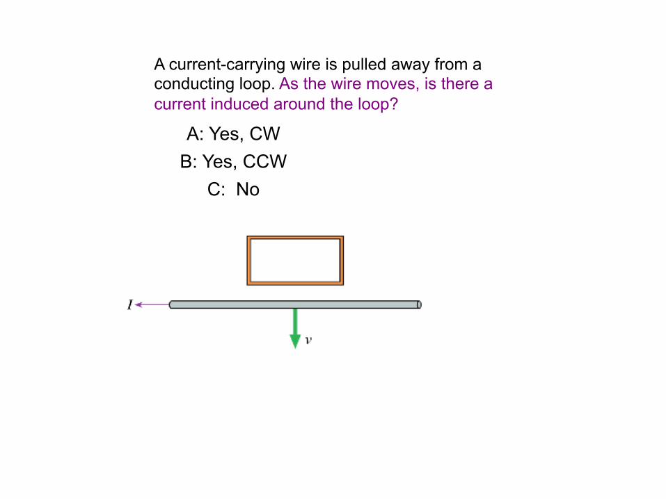
CT 33.6
A current-carrying wire is pulled away from a conducting loop. As the wire moves, is there a current induced around the loop?
A: Yes, CW
B: Yes, CCW C: No

CT 33.6c
A loop of wire is near a long straight wire that is carrying a large current I, which is decreasing with time. The loop and wire are in the same plane. The current induced in the loop is
I to the right, but decreasing
loop
A: CW B: CCW
C: No current
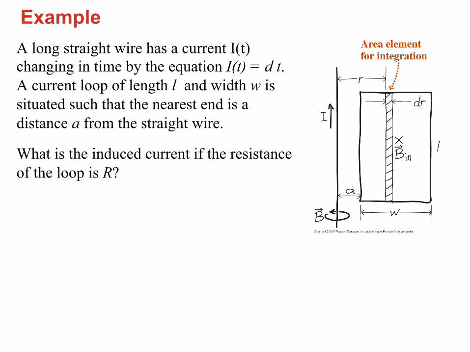
Example A long straight wire has a current I(t) changing in time by the equation I(t) = d t. A current loop of length l and width w is situated such that the nearest end is a distance a from the straight wire.
What is the induced current if the resistance of the loop is R?
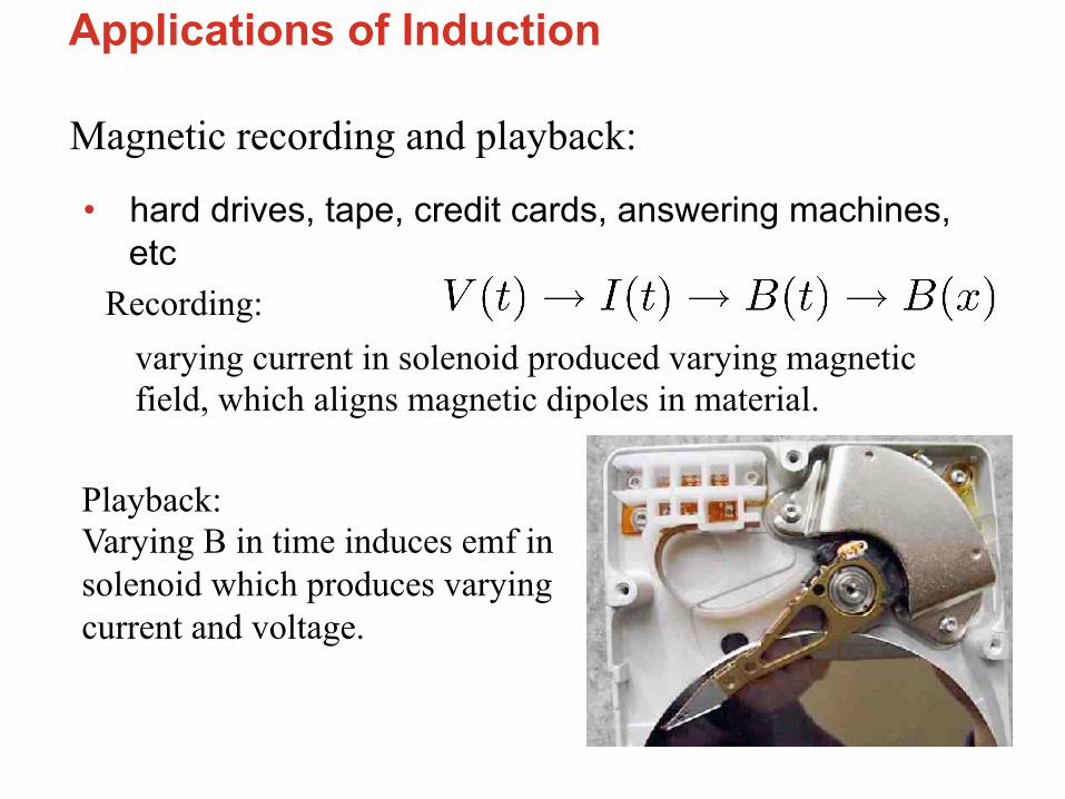
Applications of Induction
Magnetic recording and playback:
• hard drives, tape, credit cards, answering machines, etc
varying current in solenoid produced varying magnetic field, which aligns magnetic dipoles in material.
Recording:
Playback: Varying B in time induces emf in solenoid which produces varying current and voltage.

Applications Cont’d • Spark Plugs (sudden change in current produces huge EMF)
• Dynamic Microphones (sound waves move diaphragm and attached coil in magnetic field, inducing current)
• Transformers and inductors (next chapter)
• Metal Detectors (discussed with Eddy currents)
• Electric guitar pickup (strings are magnetized by permanent magnet)
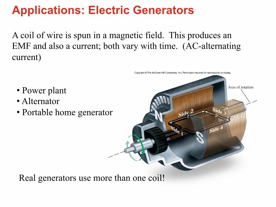
Applications: Electric Generators
A coil of wire is spun in a magnetic field. This produces an EMF and also a current; both vary with time. (AC-alternating current)
• Power plant • Alternator • Portable home generator
Real generators use more than one coil!

http://www.sciencejoywagon.com/physicszone/otherpub/wfendt/generatorengl.htm
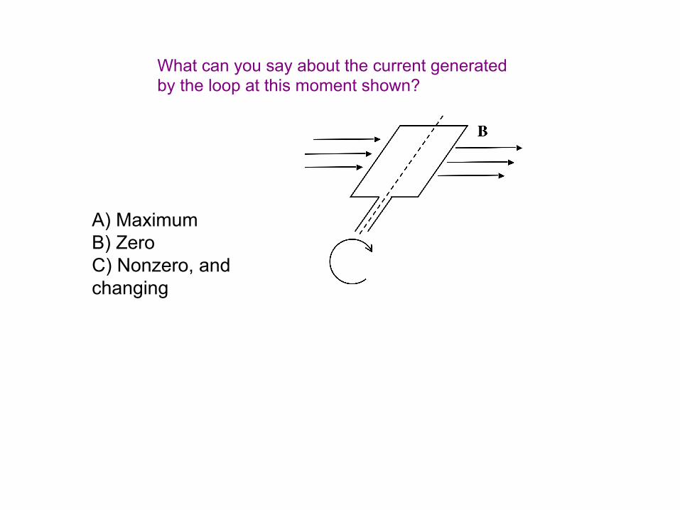
CT 33.8b
What can you say about the current generated by the loop at this moment shown?
A) Maximum B) Zero C) Nonzero, and changing
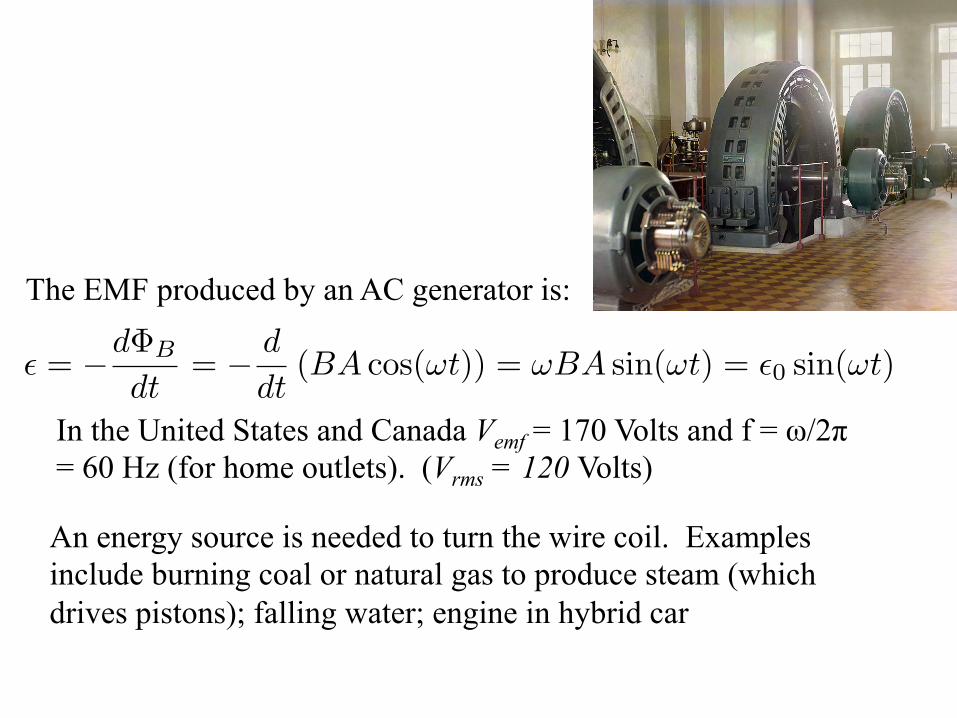
The EMF produced by an AC generator is:
In the United States and Canada Vemf = 170 Volts and f = ω/2π = 60 Hz (for home outlets). (Vrms = 120 Volts)
An energy source is needed to turn the wire coil. Examples include burning coal or natural gas to produce steam (which drives pistons); falling water; engine in hybrid car
� = −dΦB
dt= − d
dt(BA cos(ωt)) = ωBA sin(ωt) = �0 sin(ωt)

Example An electric generator consists of a 100-turn circular coil 50 cm in diameter. Its rotated at f=60 Hz inside a solenoid of radius 75 cm and winding density n = 50 cm-1. What DC current in the solenoid is needed for the the maximum emf of the generator to be 170 V?

Eddy Currents Eddy currents are induced currents in a large (2D or 3D) chunk of a conductor (moving through a B field or in a changing B field)
Applications: Roller coaster car breaking, induction stoves, magnetic levitation (trains), metal detectors, etc

• The windings of a long solenoid carrying a current I
• Where does the emf in the wire loop come from? What actually drives the current? How does the wire know that the B field changed inside the solenoid?
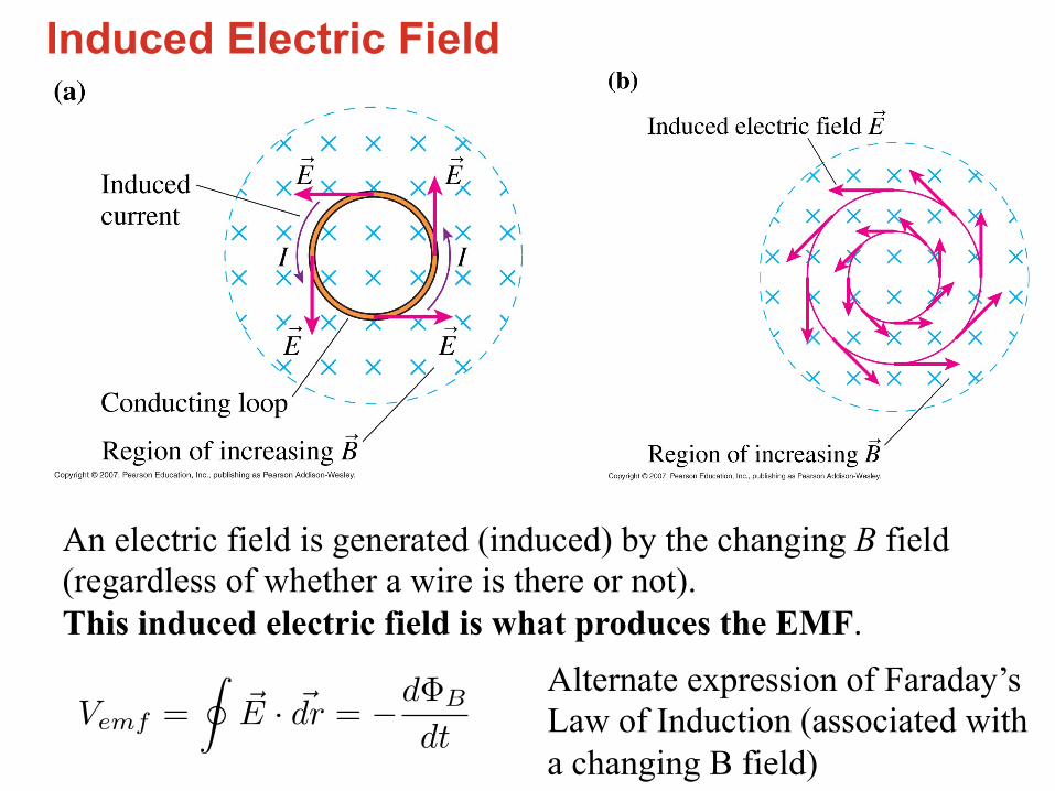
Induced Electric Field
An electric field is generated (induced) by the changing B field (regardless of whether a wire is there or not). This induced electric field is what produces the EMF.
Vemf =
��E · �dr = −dΦB
dt
Alternate expression of Faraday’s Law of Induction (associated with a changing B field)

��E · d�r = −dΦB
dt
E(r, t) =R2
2r
dB
dt2πrE =
dB
dtπR2 (r > R)
What is the electric field?
Outside solenoid:

��E · d�r = −dΦB
dt
2πrE =dB
dtπr2 E =
dB
dt
r
2(r < R)
Inside solenoid:

Mutual Inductance • Consider two stationary circuits in the vicinity of each other. Current in one circuit produces a magnetic field, and thus a magnetic flux through the other circuit.
• Mutual inductance is the constant of proportion between I1 and the magnetic flux in circuit #2
• If I1 is changing, an emf is induced in circuit #2
• Mutual inductance is the basis of transformers (covered next chapter)
ΦB2 = M21I1
�2 = −dΦB2
dt= −M21
dI1dt
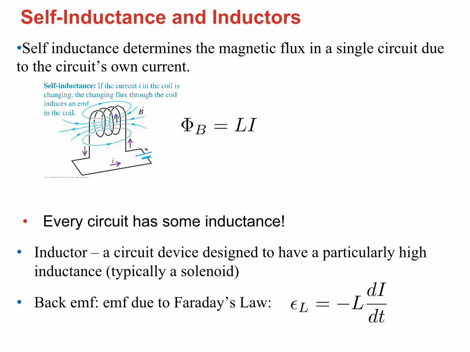
Self-Inductance and Inductors • Self inductance determines the magnetic flux in a single circuit due to the circuit’s own current.
• Every circuit has some inductance!
• Inductor – a circuit device designed to have a particularly high inductance (typically a solenoid)
• Back emf: emf due to Faraday’s Law:
ΦB = LI
�L = −LdI
dt

CT 33.23
Two long solenoids, each of inductance L, are connected together to form a single very long solenoid of inductance Ltotal. What is Ltotal?
+
=
L
Ltotal = ?
L
A: L B: 2L C: 4L D: 8L
E: other
L L
L(total)=?
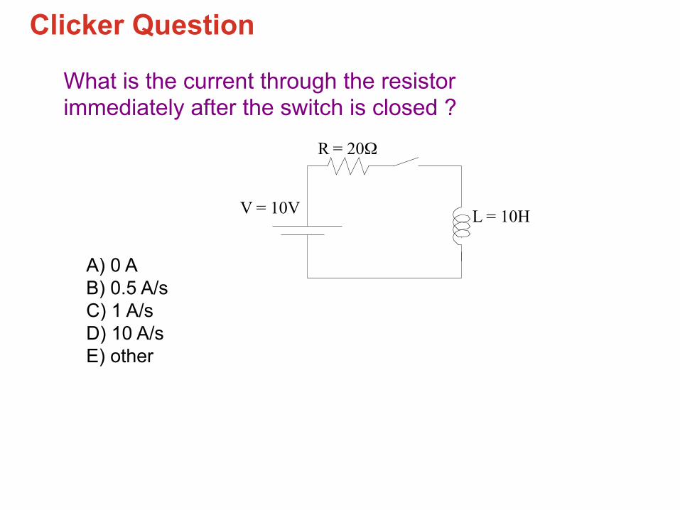
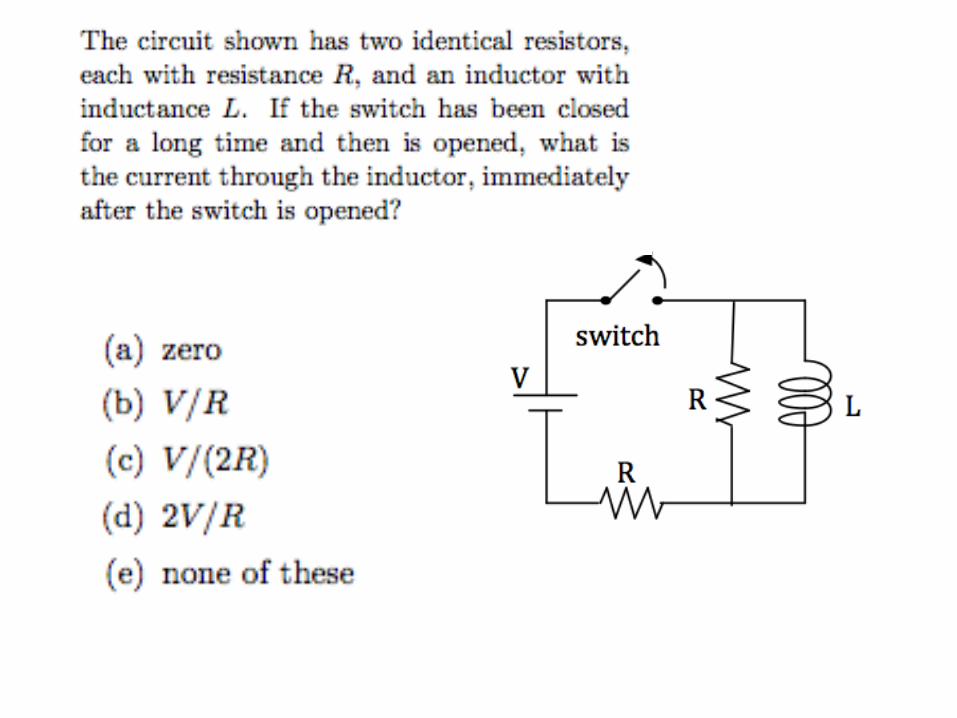
CT 33.28
What is the current through the resistor immediately after the switch is closed ?
L = 10H V = 10V
R = 20!
A) 0 A B) 0.5 A/s C) 1 A/s D) 10 A/s E) other
Clicker Question
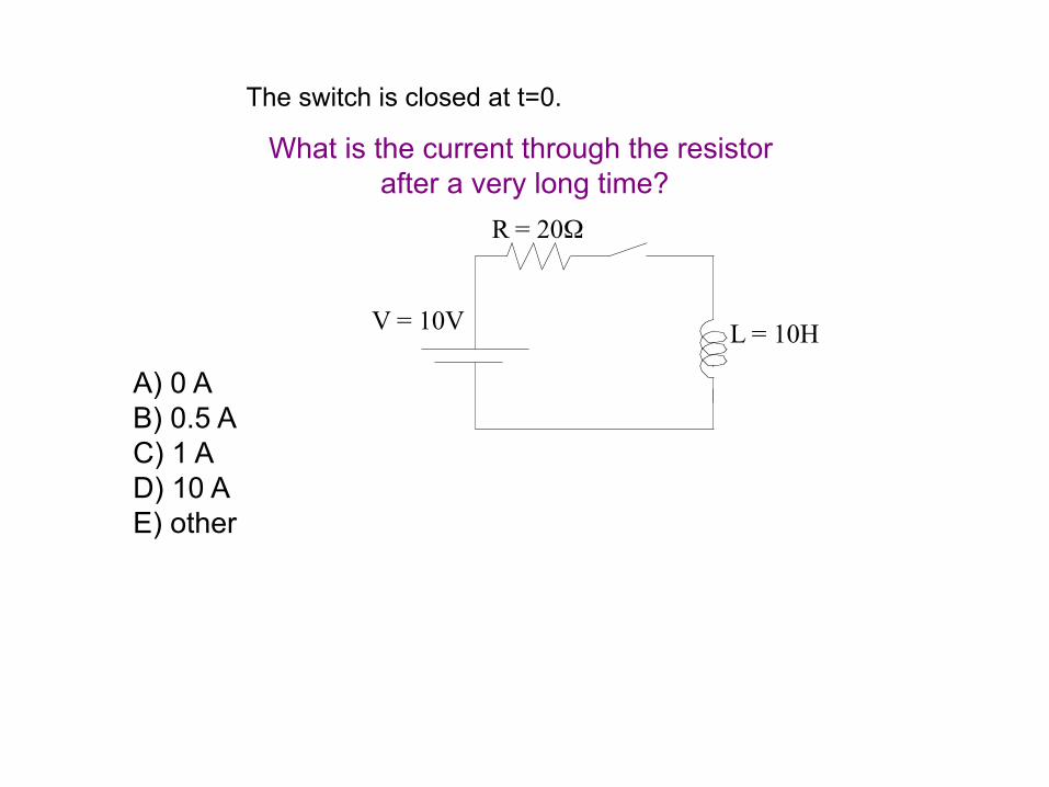
CT 33.29
The switch is closed at t=0.
What is the current through the resistor
after a very long time?
L = 10H V = 10V
R = 20!
A) 0 A B) 0.5 A C) 1 A D) 10 A E) other

What is voltage at top and bo1om of inductor right a7er switch is closed (I=0)?
1. Vtop = ξ0, Vbo-om= 0
2. Vtop = 0, Vbo-om = 0
3. Vtop = ξ0, Vbo-om=ξ0
4. WTF (huh?)?! This seems wrong. Seems to depend how I look at it…
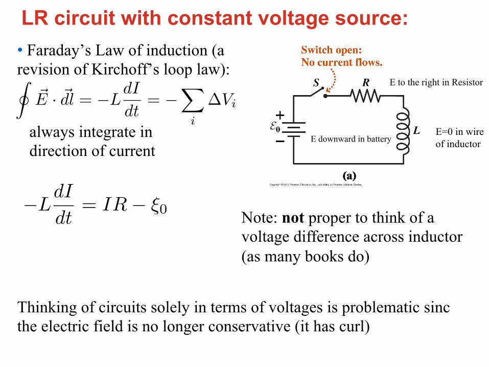
LR circuit with constant voltage source: • Faraday’s Law of induction (a revision of Kirchoff’s loop law):
Note: not proper to think of a voltage difference across inductor (as many books do)
always integrate in direction of current
��E · �dl = −L
dI
dt= −
�
i
∆Vi
E=0 in wire of inductor
E to the right in Resistor
E downward in battery
−LdI
dt= IR− ξ0
Thinking of circuits solely in terms of voltages is problematic sinc the electric field is no longer conservative (it has curl)
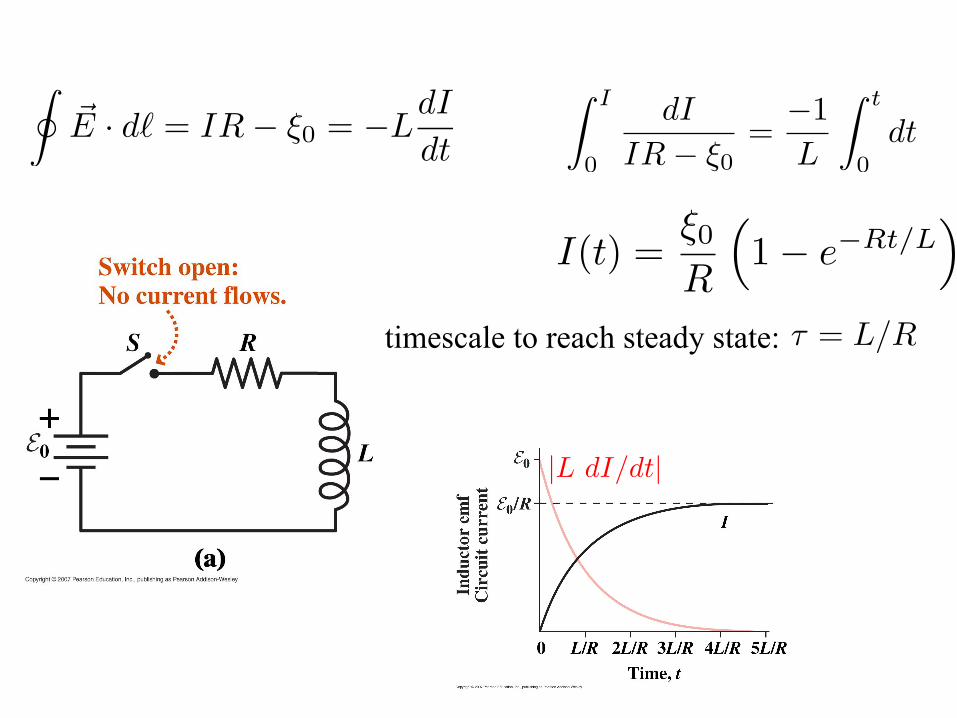
I(t) =ξ0
R
�1− e−Rt/L
�
��E · d� = IR− ξ0 = −L
dI
dt
� I
0
dI
IR− ξ0=−1L
� t
0dt
timescale to reach steady state: τ = L/R
|L dI/dt|

Back emf in motor circuit Notice that an electric motor can act as a generator (this is the principle behind hybrid cars)
So, for an electric motor circuit, the rotating coil will generate a back emf (this emf causes the current to be smaller than what it would be without a back emf)