chapter 2 tool design and construction for sand casting
TRANSCRIPT
Chapter 2 Tool Design and Construction for Sand Casting
2.1 Sand-Casting Tool Design and Construction
Typically, the sand-casting tool design and fabrication process begins when the tool builder receives the part design from the client or design engineer. In general, the part design can be communicated in variety of ways such as by a physical part, a 2D engineering drawing, a 3D computer generated solid model, or other means that sufficiently conveys the design intent needed for tooling design and fabrication.
Given this initial part design data set and a general understanding
of the cost, lead-time, accuracy, and production volume requirements of the casting, the tool builder must decide on the best approach for constructing the tooling (pattern, core boxes, etc.) needed to produce the sand casting. This requires a deep understanding of the sand casting process and of foundry operations. In designing and building a pattern, the tool builder must consider a large range of often conflicting considerations and requirements and then design the pattern to achieve the best possible balance of cost, quality, and time. Primary considerations include:
• The functionality of the casting. • How to best achieve the specified external and internal shape
of the casting. • How molten metal will flow during filling and feed during
solidification of the casting. • How the casting will shrink during solidification and cooling
to room temperature. • Where the parting line should be located to best facilitate
foundry operations. • Where and how much draft should be applied. • Where and how much extra material should be provided for
machining.
© Springer Science+Business Media, LLC 2010 Mechanical Engineering Series, DOI 10.1007/978-1-4419-5731-3_2,
11W. Wang et al., Rapid Tooling Guidelines For Sand Casting,
• What type of pattern should be used. • What fabrication process should be used to construct the
pattern. • What pattern material should be used.
Traditional pattern making is performed in a woodworking shop
equipped with a compete line of woodworking equipment (band saw, table saw, jointer, planer, drill press, disc sander, spindle sander, and layout tables). Manually building a pattern requires producing a three dimensional shape from a two-dimensional drawing. The pattern shape is usually constructed from a variety of separate pieces that are glued and/or fastened together. Draft is added to facilitate withdrawal of the pattern from the sand and dimensions are modified to provide extra metal where the casting will be finish machined. After the pattern is assembled, fillets are added by gluing in leather fillet material or using plastic material specially formulated for this purpose. A key factor that influences every stage of the pattern design and construction is the requirement that the pattern be able to withstand the repeated fractions of the molding process in a foundry environment.
The patternmaker must also decide on the number and shape of
the cores required and then design and build the associated core boxes. To do this, the patternmaker must visualize what the negative shape looks like and how it will be assembled in the mold to produce the desired internal geometry. It is important to note that not all pattermakers are proficient at designing cores. For example, if a particular pattern shop or foundry does a lot of automotive or aircraft engine work, where internal complexity is high, it is likely that they will be proficient at core fabrication. Patternmakers who work in shops where simpler shapes such as frames are produced, however, may not be as experienced with cores. Designing and building sand casting tooling that includes complex arrangements of cores that will run successfully in the foundry benefits from experience and skill. Each core must have a shape that can be easily produced by the core maker and handled by the foundry. It must also be easily assembled into the mold without interfering with other cores or mold parts. One of the critical issues is that the cores must be correctly located and positively held in place to assure consistency from casting to casting.
12 Rapid Tooling Guidelines For Sand Casting
In some cases a template or fixture is used to assure proper core alignment.
EngineeringDrawing or Other
Input Data Set
ManualFabrication
Computer-AidedFabrication
Create 3DSolid Model
• Select Parting Line• Add Shrinkage• Add Draft
CNC MachiningFabrication
Fast FreeformFabrication
FinishedPattern
Figure 2.1 Tool fabrication process for sand casting
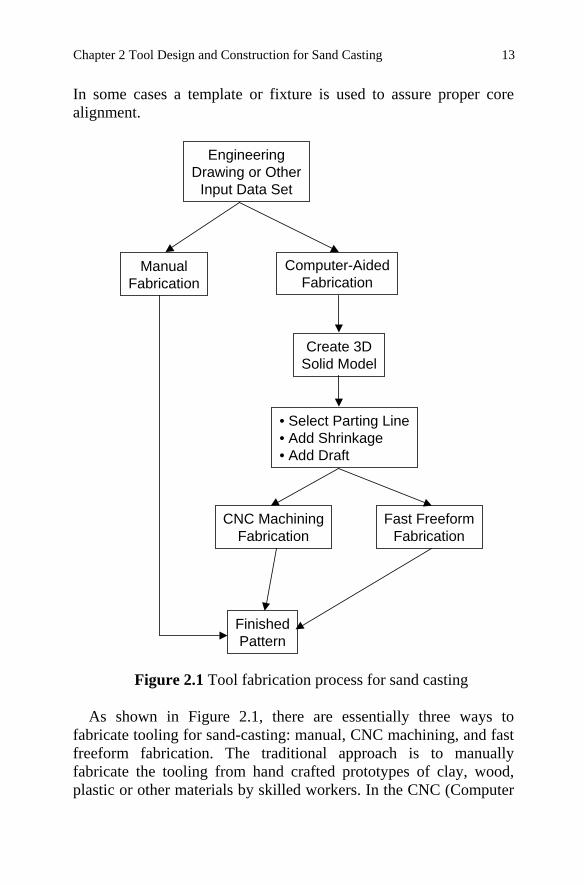
As shown in Figure 2.1, there are essentially three ways to
fabricate tooling for sand-casting: manual, CNC machining, and fast freeform fabrication. The traditional approach is to manually fabricate the tooling from hand crafted prototypes of clay, wood, plastic or other materials by skilled workers. In the CNC (Computer
13 Chapter 2 Tool Design and Construction for Sand Casting
Numerical Control) machining approach, the tooling is produced by removing material from a workpiece using the machining process (subtractive process). In the fast freeform fabrication method, tooling is created by building up one layer at a time (additive process). The CNC machining and fast freeform fabrication approaches are also known as computerized patternmaking or rapid tooling because they utilize the computer to control the fabrication process. Consequently, a 3D solid model representation of the part is required to use these fabrication methods.
When 3D data or a solid model is available, the pattern and cores
can be fabricated by utilizing rapid tooling methods. In the case of simple shapes like a frame, these fabrication alternatives may not offer much advantage over traditional manual methods. However, when the configuration is more complex (e.g., blends, sweeping shapes, bosses in various attitudes), very dramatic savings in time and improvement in accuracy is often possible with these newer methods. Substantial cost savings are also usually possible since the casting will typically get through first article or volume production ready inspection in the foundry with less iteration.
It should be noted that even with relatively complicated part
geometry, manual pattern fabrication is often the fastest and most economical fabrication method because of the complex preprocessing and set-up activities required by rapid tooling processes. However, computerized patternmaking is being greatly facilitated by the introduction of dedicated mold and pattern manufacturing software packages. These programs work with solid models to rapidly create parting lines, introduce allowances, add draft, generate mold and core shapes, and create other tool engineering features.
Ultimately, the choice of tooling fabrication method depends on
tradeoffs between lead-time, cost and accuracy. It is also dependent on the availability of a solid model representation of the finished casting geometry. If a solid model of the finished casting is not available or cannot be created, then manual fabrication is the only alternative. The availability of a solid model can also effect the number of iterations required to achieve first article acceptance in
14 Rapid Tooling Guidelines For Sand Casting

the foundry. For example, shrinkage generally occurs in the direction of the local center of mass, but not the geometric center of the part. As a result, when shrink factors are applied globally, which is often the case in manual fabrication, it is frequently necessary to re-work the tooling to achieve an acceptable casting. With the combination of a CAD solid model and rapid tooling methods, shrinkage factors can be applied locally rather than globally, thereby possibly avoiding rework of the tooling. In all cases, however, the exact amount of shrinkage and draft that is applied, either locally or globally, is determined by tooling standards and/or experience. Hence, some uncertainty in the tooling design is unavoidable regardless of the fabrication method used.
There are a number of documented cases in which complex
castings (e.g., a pump housing with fifteen cores) were successfully produced on the first attempt with zero deviations from design intent. In the great majority of these cases, the tooling was produced using CNC machining by a skilled tool builder having extensive experience in the design and construction of complex tooling. In all cases, the key success factor was early identification of the tool builder and foundry having the right level of capability and experience for the particular casting in question. With the right tool builder and foundry, the need to add a cost margin for uncertity into the price of the tooling either by the tool builder or the foundry is reduced. Ultimately, the end user gets a viable part in less time and for less cost.
2.2 Pattern Type
There are several types of patterns used in foundry practice. The pattern type can be categorized as follows:
• single or loose pattern • gated pattern • match-plate pattern • cope and drag pattern • special patterns and device
15 Chapter 2 Tool Design and Construction for Sand Casting
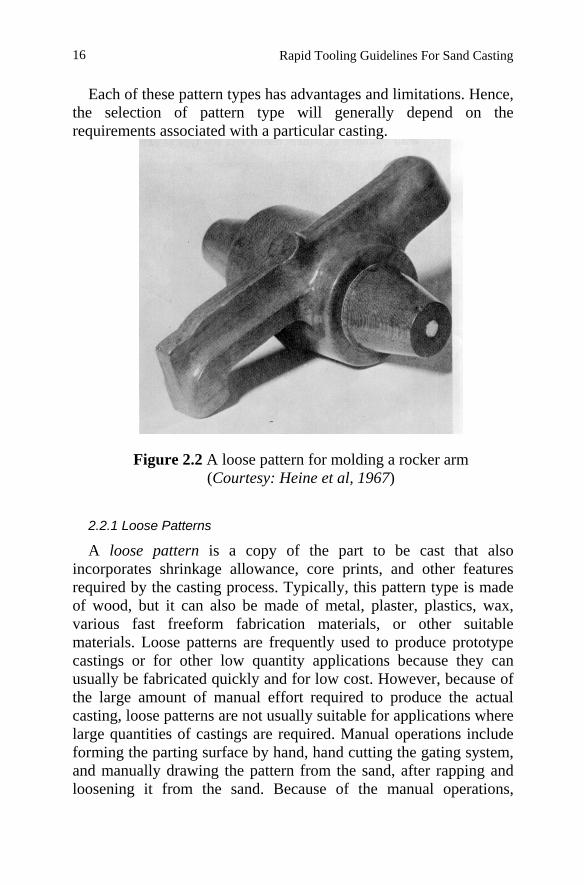
Each of these pattern types has advantages and limitations. Hence, the selection of pattern type will generally depend on the requirements associated with a particular casting.
Figure 2.2 A loose pattern for molding a rocker arm (Courtesy: Heine et al, 1967)
2.2.1 Loose Patterns
A loose pattern is a copy of the part to be cast that also incorporates shrinkage allowance, core prints, and other features required by the casting process. Typically, this pattern type is made of wood, but it can also be made of metal, plaster, plastics, wax, various fast freeform fabrication materials, or other suitable materials. Loose patterns are frequently used to produce prototype castings or for other low quantity applications because they can usually be fabricated quickly and for low cost. However, because of the large amount of manual effort required to produce the actual casting, loose patterns are not usually suitable for applications where large quantities of castings are required. Manual operations include forming the parting surface by hand, hand cutting the gating system, and manually drawing the pattern from the sand, after rapping and loosening it from the sand. Because of the manual operations,
16 Rapid Tooling Guidelines For Sand Casting
casting dimensions are also likely to vary from casting to casting. Figure 2.2 shows a loose pattern for molding a rocker arm.
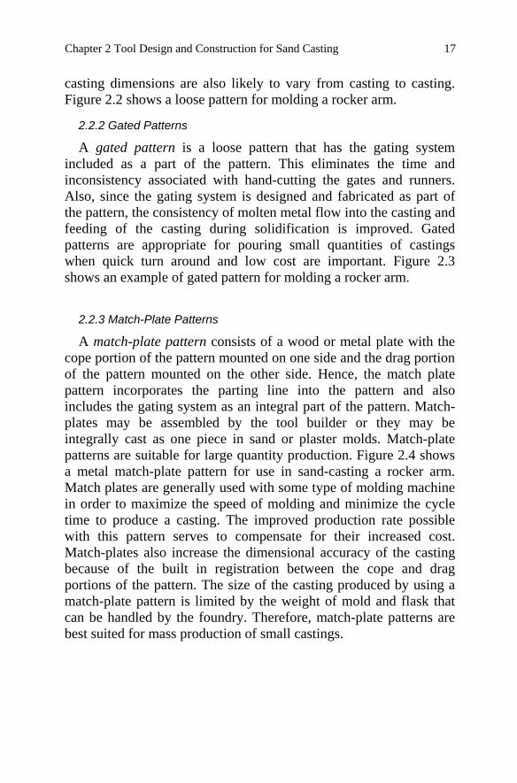
2.2.2 Gated Patterns
A gated pattern is a loose pattern that has the gating system included as a part of the pattern. This eliminates the time and inconsistency associated with hand-cutting the gates and runners. Also, since the gating system is designed and fabricated as part of the pattern, the consistency of molten metal flow into the casting and feeding of the casting during solidification is improved. Gated patterns are appropriate for pouring small quantities of castings when quick turn around and low cost are important. Figure 2.3 shows an example of gated pattern for molding a rocker arm.
2.2.3 Match-Plate Patterns
A match-plate pattern consists of a wood or metal plate with the cope portion of the pattern mounted on one side and the drag portion of the pattern mounted on the other side. Hence, the match plate pattern incorporates the parting line into the pattern and also includes the gating system as an integral part of the pattern. Match-plates may be assembled by the tool builder or they may be integrally cast as one piece in sand or plaster molds. Match-plate patterns are suitable for large quantity production. Figure 2.4 shows a metal match-plate pattern for use in sand-casting a rocker arm. Match plates are generally used with some type of molding machine in order to maximize the speed of molding and minimize the cycle time to produce a casting. The improved production rate possible with this pattern serves to compensate for their increased cost. Match-plates also increase the dimensional accuracy of the casting because of the built in registration between the cope and drag portions of the pattern. The size of the casting produced by using a match-plate pattern is limited by the weight of mold and flask that can be handled by the foundry. Therefore, match-plate patterns are best suited for mass production of small castings.
17 Chapter 2 Tool Design and Construction for Sand Casting
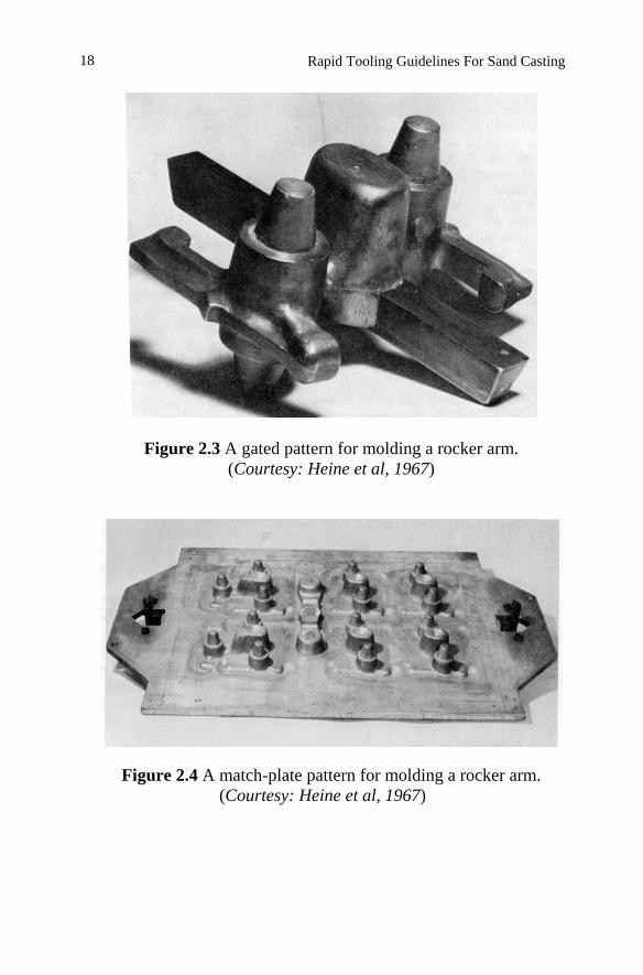
Figure 2.3 A gated pattern for molding a rocker arm. (Courtesy: Heine et al, 1967)
Figure 2.4 A match-plate pattern for molding a rocker arm. (Courtesy: Heine et al, 1967)
18 Rapid Tooling Guidelines For Sand Casting
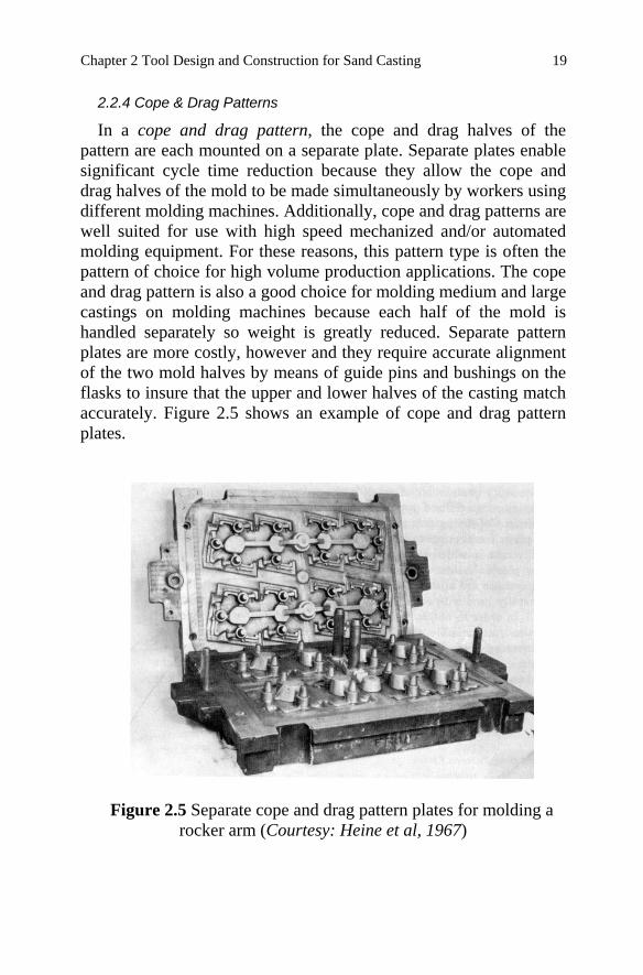
2.2.4 Cope & Drag Patterns
In a cope and drag pattern, the cope and drag halves of the pattern are each mounted on a separate plate. Separate plates enable significant cycle time reduction because they allow the cope and drag halves of the mold to be made simultaneously by workers using different molding machines. Additionally, cope and drag patterns are well suited for use with high speed mechanized and/or automated molding equipment. For these reasons, this pattern type is often the pattern of choice for high volume production applications. The cope and drag pattern is also a good choice for molding medium and large castings on molding machines because each half of the mold is handled separately so weight is greatly reduced. Separate pattern plates are more costly, however and they require accurate alignment of the two mold halves by means of guide pins and bushings on the flasks to insure that the upper and lower halves of the casting match accurately. Figure 2.5 shows an example of cope and drag pattern plates.
Figure 2.5 Separate cope and drag pattern plates for molding a rocker arm (Courtesy: Heine et al, 1967)
19 Chapter 2 Tool Design and Construction for Sand Casting
2.3 Pattern Design
Pattern design includes all of the factors that must be considered by the tool builder when creating the pattern and core boxes for a given sand-casting application. The master pattern is the original pattern that is designed and fabricated by the tool builder. In some situations, production patterns may be generated from the master pattern. For example, several copies of a master pattern might be cast and mounted on a match plate for high volume production. In other situations, the master pattern may be directly used by the foundry to produce castings. The discussion that follows applies equally to both to the master pattern and production pattern if they are not the same.
2.3.1 Pattern and Core Box Materials
Several materials are used for master pattern construction. Each has its advantages in different applications.
Wood Wood materials are widely used in the foundry industry. The most
frequently used types of wood include pine, poplar, mahogany, and cherry. Because it is soft, white pine is usually the least costly and easiest to work with. However, pine has poor wear resistance and is prone to warpage due to changes in moisture content. Poplar is a hardwood with good strength and abrasion resistance, however, like pine it tends to warp. If properly laminated or segmented and coated, warpage can be minimized. Honduran mahogany is hard and fairly stable and, for these reasons, it is usually the wood of choice for high quality production wood patterns. Cherry is also good for production wood patterns; it is harder than mahogany and is easy to work.
Mounting a wood pattern helps to maintain its shape. All wood
patterns should be properly segmented to offset the effects of grain orientation. Each segment should be glued and secured with screws. Nailed pattern construction should be avoided wherever possible. To increase the life of a wood pattern, coreprints and other areas prone to wear can be made of hard maple or birch.
Metal
20 Rapid Tooling Guidelines For Sand Casting
Metal patterns are particularly well suited for long production runs. Compared to wood, metal is more abrasion resistant and less subject to warpage. Tighter dimensional tolerances can be held with metal tooling compared to wood. Metal patterns are usually made of cast aluminum or cast iron, but steel and other metals are also occasionally used. Stainless steel is increasing in popularity as a pattern material because it is easier to weld and does not corrode or rust. Metal patterns can be cast to size with little or no machining, or they may be fully machined. In either case, the finishing of the pattern requires considerable polishing. In fact, finishing operations may represent 50% or more of the total pattern construction time.
Some areas of a pattern or core box may be more prone to wear or
require tighter tolerances. Examples include locating points, fixture locations, core prints, etc. Hardened steel or polyurethane inserts are occasionally used at these critical points for improved wear and stability. Because of the high temperatures needed for thermally setting resins, the shell molding and core making process necessitates the use of metal equipment. Since aluminum tends to gall and wear rapidly at high temperature, cast iron or certain copper alloys, such as bronze or chrome-copper, are recommended.
Plastic Plastic materials are being increasingly used in modern foundry
practice. Epoxy resins, which are bonded to reinforcing materials have high strength and have proven to be very acceptable as pattern materials. Epoxy resin patterns have many advantages including good dimensional stability, high compressive strength, good abrasion resistance, resistance to chemical attack, high bending strength, and easy release from the molding sand.
Unreinfored epoxy patterns are satisfactory for small pieces and
limited production. An iron or carbide-filled epoxy surface coat backed by fiberglass or epoxy resin with wood filler can be used for higher production patterns. This type of construction can be an ideal alternative to an expensive large metal cope and drag pattern. Reworking or repairing an epoxy pattern such as this however may be quite difficult.
21 Chapter 2 Tool Design and Construction for Sand Casting
Polyurethane elastomer is also extensively used. In addition to having excellent wear qualities this material is less brittle than epoxy materials and has greater resistance to chipping. Polyurethane is used for complete patterns, wear-resistant inserts, and loose pieces. Core boxes made with a urethane elastomer must be reinforced with wood or aluminum.
Another advantage of using plastics (either urethane or epoxy) is
that complete patterns and core boxes can be inexpensively duplicated from an existing wood master.
Styrofoam Styrofoam patterns are most commonly used in the full mold
casting process. In this process, the polystyrene pattern is left in the sand mold during the pouring of the molten metal. The heat causes the pattern to decompose into liquid and then gas. Special glues and coatings are used in the construction of foam patterns for this process.
Polystyrene is a hydrocarbon existing as a long chain polymer
which consists of 92% carbon and 8% hydrogen by weight. Styrofoam patterns can be fabricated from 4 by 8 foot polystyrene sheets with thickness which range from 1 to 12 inches (25.4 to 304.8 mm). Not all styrofoam can be used as pattern material. The recommended density for pattern material is 1 to 1.25 lb/ft3 (16 to 20 kg/m3). Less dense polystyrene is not strong enough while heavier polystyrene is unsuitable because it leaves behind excessive contaminating residues in the full mold process.
The primary advantages of styrofoam patterns and the full mold
process is the reduced cost compared to the traditional sand-casting process. Mold fabrication time is less and frequently cores may be eliminated. When high production runs are required, the styrofoam patterns can be produced by injection molding.
Fast Freeform Fabrication Materials Fast freeform fabrication materials are diverse because of the
many different fast freeform processes that are commonly used. Fast
22 Rapid Tooling Guidelines For Sand Casting
freeform processes that have found wide use in foundry tooling production include the following:
• Stereolithography (SLA): this process builds the model one
layer at a time by exposing ultra violet cured epoxy resin to laser light. SLA models look like unreinforced epoxy resin.
• Laminated Object Manufacturing (LOM): this process builds the model by gluing sheets of paper together in a stack, one layer at a time after each sheet has been cut out by a laser. A completed LOM model looks like it is made out of wood.
• Selective Laser Sintering (SLS): this process builds the model up by depositing and sintering layers of powder. A variety of powders can be used such as metal powder, ABS plastics, etc.
• Fused Deposition Modeling (FDM): in this process, the model is built by extruding thermal plastic or wax to form each layer.
Models produced by fast freeform fabrication processes can be
used as a one-time throw away pattern or core or they can be used as a master pattern or core box, either to produce short run castings or to make plastic tooling as discussed above.
2.3.2 Pattern Allowances
When designing a pattern, it is often necessary to modify the dimensions of the pattern to account for particular characteristics or requirements of the casting process. Allowances that are commonly applied as part of the pattern design process include shrinkage allowance, distortion allowance, machining allowance, and finish allowance.
Shrinkage allowance (Blair and Stevens, 1995) Shrinkage allowance is a correction factor built into the pattern
that compensates for dimensional changes that occur as the casting solidifies and cools to room temperature. Since metal contracts as it cools, the pattern is typically made larger than finished part dimensions so that when the casting has cooled to room temperature, its dimensions are at design intent (i.e., the same as those shown on the data representation or drawing within acceptable tolerances).
23 Chapter 2 Tool Design and Construction for Sand Casting
This allowance for contraction is often called “patternmaker’s allowance.”
The amount of shrinkage allowance that must be applied depends
on the following factors:
• Casting alloy • Resistance of the mold to contraction of the casting • Foundry practice
Since different metals contract differently as they cool, the casting
alloy determines the starting value for the shrinkage allowance. For example, most aluminum casting alloys have a shrinkage allowance that ranges from 3/32 inch/foot to 5/32 inch/foot (7.8 mm/m to 13.0 mm/m). For carbon and low-alloy steels, the shrinkage allowance is 3/16 inch/foot while 5/16 inch/foot (15.6 mm/m to 26.0 mm/m) is used for austenitic alloys. Because each particular casting alloy shrinks differently, the pattern must be designed for a specific alloy and once designed, the pattern is generally not suitable for use in casting a different alloy.
The resistance of the mold to contraction of the casting, which is influenced by the casting shape and the mold material, is also an important consideration. Consider, for example, the casting shown in Figure 2.6. For this casting, length dimension “X” has virtually no constraint on its ability to contract since the casting will pull away from the mold walls as it shrinks. Hence, the full value of patternmaker’s allowance would be applied to dimension “X.” Contraction of diameter “Y”, on the other hand, is moderately to severely constrained depending on the stiffness (i.e., rigidity) of the core used to form the hole. Therefore, little or no patternmaker allowance would be applied to this dimension. It is clear from this example that application of patternmaker’s allowance is highly dependent on judgement and experience. Also, shape of the casting can strongly influence the amount of local shrinkage that occurs. Other mold features, such as mold rigidity, risers, gates, and so forth can also constrain casting shrinkage. When close tolerances are required on a particular dimension, a larger-than-normal shrinkage allowance may be initially applied. The pattern is then corrected
24 Rapid Tooling Guidelines For Sand Casting
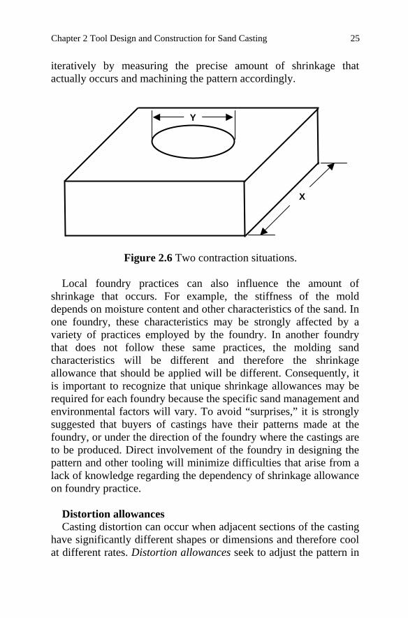
iteratively by measuring the precise amount of shrinkage that actually occurs and machining the pattern accordingly.
Figure 2.6 Two contraction situations.
Local foundry practices can also influence the amount of
shrinkage that occurs. For example, the stiffness of the mold depends on moisture content and other characteristics of the sand. In one foundry, these characteristics may be strongly affected by a variety of practices employed by the foundry. In another foundry that does not follow these same practices, the molding sand characteristics will be different and therefore the shrinkage allowance that should be applied will be different. Consequently, it is important to recognize that unique shrinkage allowances may be required for each foundry because the specific sand management and environmental factors will vary. To avoid “surprises,” it is strongly suggested that buyers of castings have their patterns made at the foundry, or under the direction of the foundry where the castings are to be produced. Direct involvement of the foundry in designing the pattern and other tooling will minimize difficulties that arise from a lack of knowledge regarding the dependency of shrinkage allowance on foundry practice.
Distortion allowances Casting distortion can occur when adjacent sections of the casting
have significantly different shapes or dimensions and therefore cool at different rates. Distortion allowances seek to adjust the pattern in
Y
X
25 Chapter 2 Tool Design and Construction for Sand Casting
such a way that any distortion that occurs will act to cause the casting to be of the proper shape and size when cool. Distortion allowances are often applied to large, flat areas, U-shaped sections, circular sections, and other areas that tend to distort during solidification and cooling of the casting. A review of experience with similar castings can help in predicting restraint and warpage and is often a good place to start if distortion is a concern. If appropriate, this experience can be applied to the design of the new pattern.
Frequently, distortion is discovered to be a problem during try-out
of the tooling. In some cases, minor distortions found in castings can be corrected by mechanical means. If the distortion is consistent or prominent, it may be possible to make changes to the pattern dimensions and shape, to counteract these distortions. When patterns are to be changed, it is important to involve the design engineer, the buyer, the foundry engineer, and other interested parties to insure that all ramifications of the change are properly considered. These discussions should consider future production, dimensional tolerances, and other factors that may influence the cost of pattern equipment or casting production.
Machining allowances Machining allowance is the amount by which dimensions on a
casting are made oversize to provide stock for machining. Dimensions on a pattern drawing include machining allowance. The amount of metal left for machining must be no more than necessary but enough to assure that cutters can get an ample bite beneath and completely remove the hard scale and surface skin of the casting. The necessary allowance depends on a variety of considerations including the size and shape of the casting, the surface to be machined, the pouring position, the tendency to warp, the machining set-up and fixturing, and so forth.
Casting finish allowance When large quantities of castings are required, patterns may be
deliberately made oversize by applying a finish allowance. The prototype or first castings produced are then measured. Based on
26 Rapid Tooling Guidelines For Sand Casting
these results, the patterns may or may not be machined to the final size to achieve the desired casting dimensions.
2.3.3 Draft
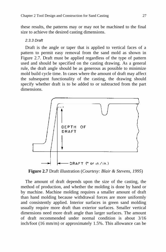
Draft is the angle or taper that is applied to vertical faces of a pattern to permit easy removal from the sand mold as shown in Figure 2.7. Draft must be applied regardless of the type of pattern used and should be specified on the casting drawing. As a general rule, the draft angle should be as generous as possible to minimize mold build cycle time. In cases where the amount of draft may affect the subsequent functionality of the casting, the drawing should specify whether draft is to be added to or subtracted from the part dimensions.
Figure 2.7 Draft illustration (Courtesy: Blair & Stevens, 1995)
The amount of draft depends upon the size of the casting, the
method of production, and whether the molding is done by hand or by machine. Machine molding requires a smaller amount of draft than hand molding because withdrawal forces are more uniformly and consistently applied. Interior surfaces in green sand molding usually require more draft than exterior surfaces. Smaller vertical dimensions need more draft angle than larger surfaces. The amount of draft recommended under normal condition is about 3/16 inch/foot (16 mm/m) or approximately 1.5%. This allowance can be
27 Chapter 2 Tool Design and Construction for Sand Casting
eliminated, in some cases, by using cores and/or separate pieces. These situations should be discussed with the foundry engineer.
2.3.4 Parting Line
In sand casting, the mold is divided into two halves (cope and drag) so that the pattern can be withdrawn. When the cope and drag halves are assembled, cavities in each half meet, producing the air space into which the molten casting alloy flows. From the inside, the mating junction between the mold halves appears as a line. This line also appears on the casting and is called the parting line or parting plane.
Parting in one plane is preferred since it facilitates the design and
fabrication of the pattern as well as the construction and assembly of the mold. The cost of patterns with straight parting lines is also lower, in general, compared to those that have irregular or offset parting lines.
Casting designs that are symmetrical about a centerline or plane
readily suggest the position of the parting line. Patterns should be made as “split patterns” to reduce labor and handwork in the mold. Except in the case of machine molding, offset parting lines require costly pattern equipment and skilled molding technique. For some cases, the need for an offset or irregular parting line can be avoided by modifying the casting geometry.
2.3.5 Geometry Considerations
The geometry of the casting is often a key factor in many tooling approaches and decisions. It is strongly recommended that a concurrent engineering approach in which the design engineer and foundry engineer work closely together as a team during the design of the casting be used whenever possible. By using a concurrent engineering approach, the geometry of the casting can be optimized for both functionality and ease of tooling and production. This can often result in considerable cost and lead time savings. A summary of key geometry considerations follows.
Fillets
28 Rapid Tooling Guidelines For Sand Casting
A fillet is a rounded filling along the convergence of two surfaces of a pattern. The rounded corner thus produced on the casting is also called a fillet. Fillets may be carved in wood patterns but are usually made more inexpensively of wax, plastic, wood coving, or leather. Fillet radii typically vary in size from 1/8 inch to 1 inch (3.175 mm to 25.4 mm) depending on the size, shape, and material of the casting. Fillets smooth sharp angles and corners and thus strengthen both patterns and castings. They provide for easier removal of the pattern from the sand, a cleaner mold, freer flow of metal through the mold, less washing of the sand in the mold, and fewer shrinking strains and hot tears between sections as the casting cools.
Undercuts and loose piece Any feature that prevents the pattern from being withdrawn is
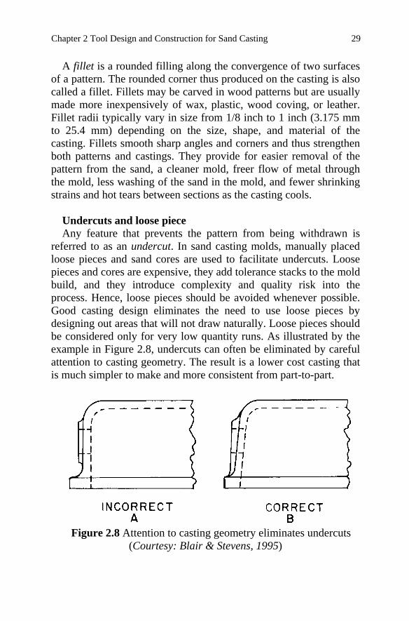
referred to as an undercut. In sand casting molds, manually placed loose pieces and sand cores are used to facilitate undercuts. Loose pieces and cores are expensive, they add tolerance stacks to the mold build, and they introduce complexity and quality risk into the process. Hence, loose pieces should be avoided whenever possible. Good casting design eliminates the need to use loose pieces by designing out areas that will not draw naturally. Loose pieces should be considered only for very low quantity runs. As illustrated by the example in Figure 2.8, undercuts can often be eliminated by careful attention to casting geometry. The result is a lower cost casting that is much simpler to make and more consistent from part-to-part.
Figure 2.8 Attention to casting geometry eliminates undercuts
(Courtesy: Blair & Stevens, 1995)
29 Chapter 2 Tool Design and Construction for Sand Casting
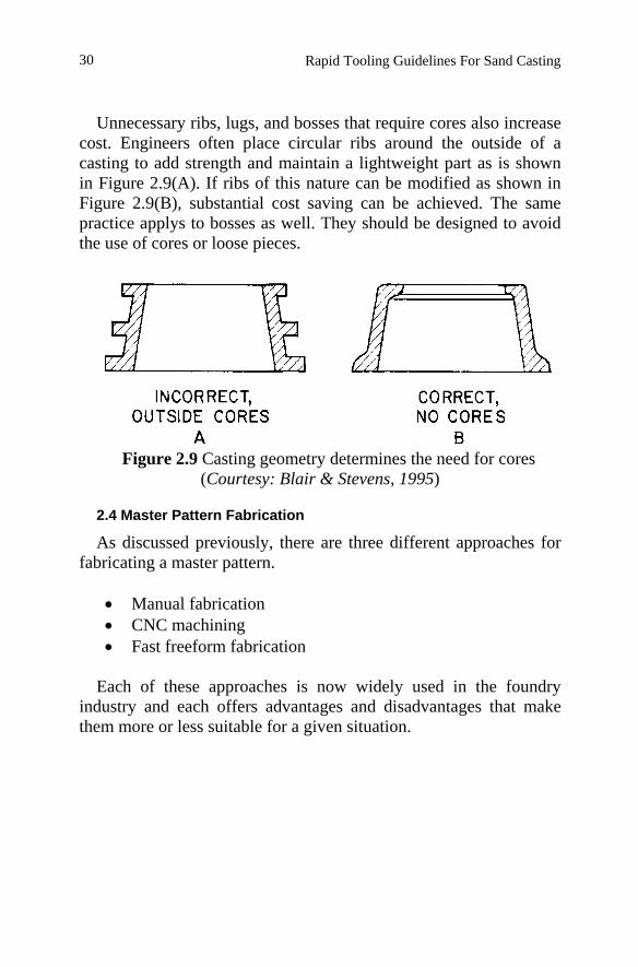
Unnecessary ribs, lugs, and bosses that require cores also increase
cost. Engineers often place circular ribs around the outside of a casting to add strength and maintain a lightweight part as is shown in Figure 2.9(A). If ribs of this nature can be modified as shown in Figure 2.9(B), substantial cost saving can be achieved. The same practice applys to bosses as well. They should be designed to avoid the use of cores or loose pieces.
Figure 2.9 Casting geometry determines the need for cores
(Courtesy: Blair & Stevens, 1995)
2.4 Master Pattern Fabrication
As discussed previously, there are three different approaches for fabricating a master pattern.
• Manual fabrication • CNC machining • Fast freeform fabrication
Each of these approaches is now widely used in the foundry
industry and each offers advantages and disadvantages that make them more or less suitable for a given situation.
30 Rapid Tooling Guidelines For Sand Casting
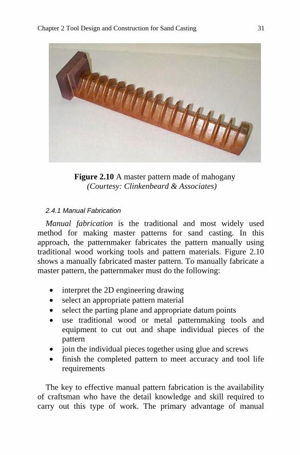
Figure 2.10 A master pattern made of mahogany (Courtesy: Clinkenbeard & Associates)
2.4.1 Manual Fabrication
Manual fabrication is the traditional and most widely used method for making master patterns for sand casting. In this approach, the patternmaker fabricates the pattern manually using traditional wood working tools and pattern materials. Figure 2.10 shows a manually fabricated master pattern. To manually fabricate a master pattern, the patternmaker must do the following:
• interpret the 2D engineering drawing • select an appropriate pattern material • select the parting plane and appropriate datum points • use traditional wood or metal patternmaking tools and
equipment to cut out and shape individual pieces of the pattern
• join the individual pieces together using glue and screws • finish the completed pattern to meet accuracy and tool life
requirements
The key to effective manual pattern fabrication is the availability of craftsman who have the detail knowledge and skill required to carry out this type of work. The primary advantage of manual
31 Chapter 2 Tool Design and Construction for Sand Casting
fabrication is its adaptability to almost any situation. The primary disadvantage is the inability of the craftsman to manually produce complex surfaces and geometry quickly and to a high degree of precision. Therefore, manual fabrication is best suited for simple parts that do not have excessive geometric complexity and/or high accuracy requirements. Although more labor intensive that the other alternatives, manual fabrication does not require the time consuming and costly up-front planning and setup activities required by computer aided rapid tooling methods. Consequently, for simple parts that do not required highly accurate features, manual fabrication is often the fastest and lowest cost pattern fabrication alternative. Also, manual fabrication is the only alternative that does not require a 3D CAD solid model representation of the part geometry.
2.4.2 Computer Numerical Control Machining
Computer numerical control machining, also called CNC machining, is a computer based approach that utilizes CNC machining processes such as milling and drilling to fabricate the pattern. In this method, a 3D CAD solid model of the part is used to drive the various CNC machining processes to machine the pattern out of a solid workpiece made of the selected pattern material. After receiving a 3D CAD solid model from the client, the tool builder modifies the file by adding necessary allowances, deciding on a parting line, dividing the model into cope and drag portions and separate pieces as required, and adding draft as necessary. The resulting solid model or solid models are then used to computer generate the tool path and machining code required by the CNC machining processes to fabricate the pattern or pattern pieces. The appropriate CNC machines are then set-up and the CNC programs executed to make the pattern pieces, which are assembled and finished to complete the pattern. The CNC machines typically used in master pattern production range from 3 to 5 axis. Figure 2.11 shows a CNC milling machine in the process of machining a master pattern.
CNC machining is the most accurate and the fastest rapid tooling
method available. Because of its inherent accuracy, CNC machining is often the method of choice for complex geometry and high
32 Rapid Tooling Guidelines For Sand Casting
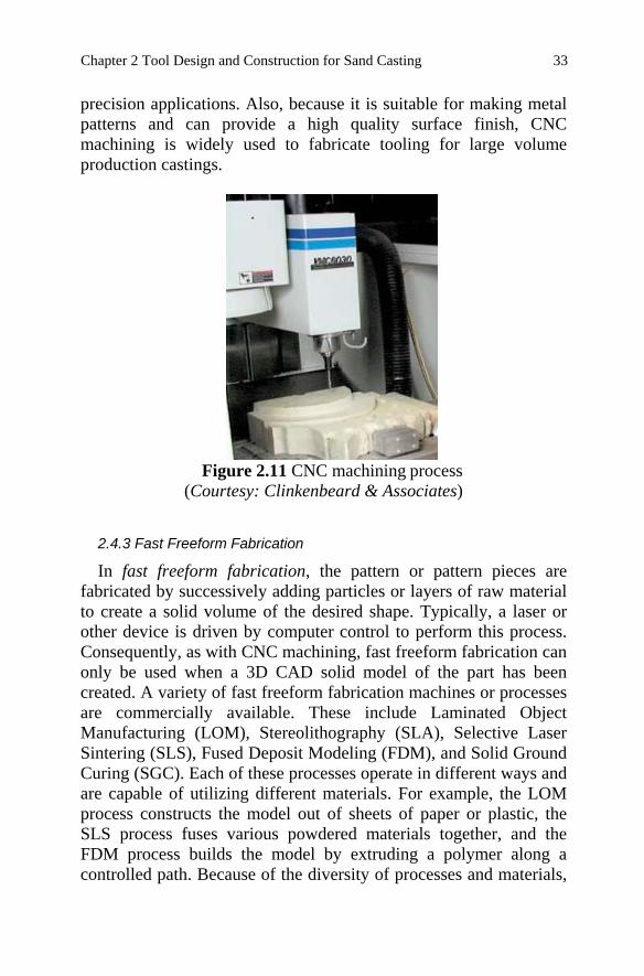
precision applications. Also, because it is suitable for making metal patterns and can provide a high quality surface finish, CNC machining is widely used to fabricate tooling for large volume production castings.
Figure 2.11 CNC machining process
(Courtesy: Clinkenbeard & Associates)
2.4.3 Fast Freeform Fabrication
In fast freeform fabrication, the pattern or pattern pieces are fabricated by successively adding particles or layers of raw material to create a solid volume of the desired shape. Typically, a laser or other device is driven by computer control to perform this process. Consequently, as with CNC machining, fast freeform fabrication can only be used when a 3D CAD solid model of the part has been created. A variety of fast freeform fabrication machines or processes are commercially available. These include Laminated Object Manufacturing (LOM), Stereolithography (SLA), Selective Laser Sintering (SLS), Fused Deposit Modeling (FDM), and Solid Ground Curing (SGC). Each of these processes operate in different ways and are capable of utilizing different materials. For example, the LOM process constructs the model out of sheets of paper or plastic, the SLS process fuses various powdered materials together, and the FDM process builds the model by extruding a polymer along a controlled path. Because of the diversity of processes and materials,
33 Chapter 2 Tool Design and Construction for Sand Casting
each fast freeform method has its own set of advantages and disadvantages. In selecting the best method for a given application, four factors need to be evaluated: accuracy, build time, strength, and post finishing.
2.5 Core and Core Box Fabrication
Cores are separate pieces that are used to shape interior surfaces and other areas of a casting that cannot be shaped by the pattern. Cores are typically made of sand that is mixed with organic binders such as linseed oil or cereal. Organic binders are preferred over clay because they break down under the heat of the molten alloy, which makes them easy to remove during shakedown. The raw sand mixture is typically molded in a core box to form the core. After molding, the core is baked in an oven to give it the strength it needs to be handled during placement in the mold and to withstand the fluid flow and buoyancy forces that may develop during filling and solidification of the casting. Ideally, the core should have enough strength to maintain integrity throughout the casting process and also collapse and revert to sand after solidification so that it is easy to remove.
2.5.1 Core Fabrication Process
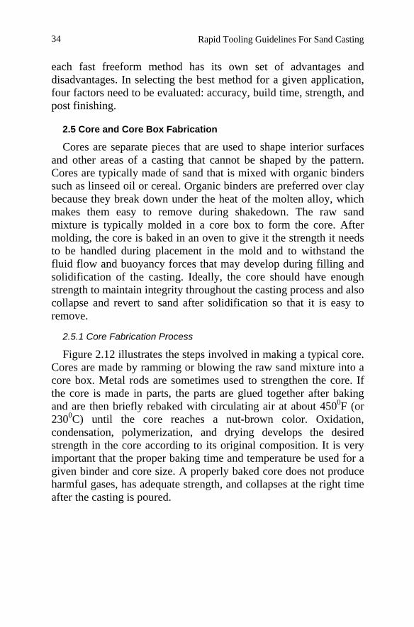
Figure 2.12 illustrates the steps involved in making a typical core. Cores are made by ramming or blowing the raw sand mixture into a core box. Metal rods are sometimes used to strengthen the core. If the core is made in parts, the parts are glued together after baking and are then briefly rebaked with circulating air at about 4500F (or 2300C) until the core reaches a nut-brown color. Oxidation, condensation, polymerization, and drying develops the desired strength in the core according to its original composition. It is very important that the proper baking time and temperature be used for a given binder and core size. A properly baked core does not produce harmful gases, has adequate strength, and collapses at the right time after the casting is poured.
34 Rapid Tooling Guidelines For Sand Casting
Figure 2.12 Making a core. (a) ramming core sand, (b) drawing the core box, (c) baking the core half (in the dielectric oven), (d) gluing the core halves, (e) “washing” the core with refractry slurry to improve casting surface finish. (Courtesy: Taylor et al, 1959)
With the development of rapid tooling technology, cores can now be directly produced using computer numerical control (CNC) machining and/or fast freeform fabrication (FFF). With the combination of the CAD/CAM techniques and rapid tooling, core design and fabrication can be performed very quickly and with high quality. Figure 2.13 shows a master core plug being produced by CNC machining. DTM Corporation has developed the SandFormTM Zr & Si materials and a Sinterstation® System to fabricate both cores and molds using a fast freeform fabrication process. Similarly, the KelToolTM process has been developed by 3D Systems Inc.
2.5.2 Core Boxes
A core box is a device for molding a core. Core boxes may be made of wood or metal, depending on the number of cores to be produced. A metal box is generally made by casting it from a wood master core box. The added cost of making and finishing a metal box is justified when a wood box would not outlast the job. Metal core boxes are usually made of aluminum and have steel strips
35 Chapter 2 Tool Design and Construction for Sand Casting
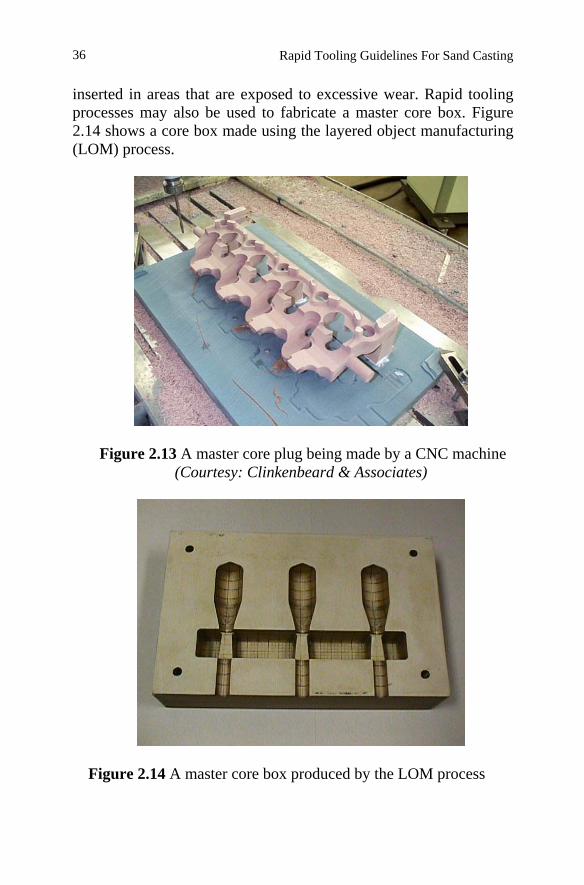
inserted in areas that are exposed to excessive wear. Rapid tooling processes may also be used to fabricate a master core box. Figure 2.14 shows a core box made using the layered object manufacturing (LOM) process.
Figure 2.13 A master core plug being made by a CNC machine (Courtesy: Clinkenbeard & Associates)
Figure 2.14 A master core box produced by the LOM process
36 Rapid Tooling Guidelines For Sand Casting

http://www.springer.com/978-1-4419-5730-6